EP4517143A1 - Suction valve, boost pump, and hydrogen supply system - Google Patents
Suction valve, boost pump, and hydrogen supply system Download PDFInfo
- Publication number
- EP4517143A1 EP4517143A1 EP23815602.0A EP23815602A EP4517143A1 EP 4517143 A1 EP4517143 A1 EP 4517143A1 EP 23815602 A EP23815602 A EP 23815602A EP 4517143 A1 EP4517143 A1 EP 4517143A1
- Authority
- EP
- European Patent Office
- Prior art keywords
- pressing member
- space part
- discharge channel
- discharge
- valve
- Prior art date
- Legal status (The legal status is an assumption and is not a legal conclusion. Google has not performed a legal analysis and makes no representation as to the accuracy of the status listed.)
- Pending
Links
Images




Classifications
-
- F—MECHANICAL ENGINEERING; LIGHTING; HEATING; WEAPONS; BLASTING
- F16—ENGINEERING ELEMENTS AND UNITS; GENERAL MEASURES FOR PRODUCING AND MAINTAINING EFFECTIVE FUNCTIONING OF MACHINES OR INSTALLATIONS; THERMAL INSULATION IN GENERAL
- F16K—VALVES; TAPS; COCKS; ACTUATING-FLOATS; DEVICES FOR VENTING OR AERATING
- F16K1/00—Lift valves or globe valves, i.e. cut-off apparatus with closure members having at least a component of their opening and closing motion perpendicular to the closing faces
- F16K1/32—Details
- F16K1/34—Cutting-off parts, e.g. valve members, seats
- F16K1/44—Details of seats or valve members of double-seat valves
-
- F—MECHANICAL ENGINEERING; LIGHTING; HEATING; WEAPONS; BLASTING
- F16—ENGINEERING ELEMENTS AND UNITS; GENERAL MEASURES FOR PRODUCING AND MAINTAINING EFFECTIVE FUNCTIONING OF MACHINES OR INSTALLATIONS; THERMAL INSULATION IN GENERAL
- F16K—VALVES; TAPS; COCKS; ACTUATING-FLOATS; DEVICES FOR VENTING OR AERATING
- F16K15/00—Check valves
- F16K15/02—Check valves with guided rigid valve members
- F16K15/06—Check valves with guided rigid valve members with guided stems
- F16K15/063—Check valves with guided rigid valve members with guided stems the valve being loaded by a spring
- F16K15/065—Check valves with guided rigid valve members with guided stems the valve being loaded by a spring spring pulling the closure member against the seat
-
- F—MECHANICAL ENGINEERING; LIGHTING; HEATING; WEAPONS; BLASTING
- F04—POSITIVE - DISPLACEMENT MACHINES FOR LIQUIDS; PUMPS FOR LIQUIDS OR ELASTIC FLUIDS
- F04B—POSITIVE-DISPLACEMENT MACHINES FOR LIQUIDS; PUMPS
- F04B15/00—Pumps adapted to handle specific fluids, e.g. by selection of specific materials for pumps or pump parts
- F04B15/06—Pumps adapted to handle specific fluids, e.g. by selection of specific materials for pumps or pump parts for liquids near their boiling point, e.g. under subnormal pressure
- F04B15/08—Pumps adapted to handle specific fluids, e.g. by selection of specific materials for pumps or pump parts for liquids near their boiling point, e.g. under subnormal pressure the liquids having low boiling points
-
- F—MECHANICAL ENGINEERING; LIGHTING; HEATING; WEAPONS; BLASTING
- F04—POSITIVE - DISPLACEMENT MACHINES FOR LIQUIDS; PUMPS FOR LIQUIDS OR ELASTIC FLUIDS
- F04B—POSITIVE-DISPLACEMENT MACHINES FOR LIQUIDS; PUMPS
- F04B17/00—Pumps characterised by combination with, or adaptation to, specific driving engines or motors
- F04B17/03—Pumps characterised by combination with, or adaptation to, specific driving engines or motors driven by electric motors
-
- F—MECHANICAL ENGINEERING; LIGHTING; HEATING; WEAPONS; BLASTING
- F04—POSITIVE - DISPLACEMENT MACHINES FOR LIQUIDS; PUMPS FOR LIQUIDS OR ELASTIC FLUIDS
- F04B—POSITIVE-DISPLACEMENT MACHINES FOR LIQUIDS; PUMPS
- F04B53/00—Component parts, details or accessories not provided for in, or of interest apart from, groups F04B1/00 - F04B23/00 or F04B39/00 - F04B47/00
- F04B53/10—Valves; Arrangement of valves
-
- F—MECHANICAL ENGINEERING; LIGHTING; HEATING; WEAPONS; BLASTING
- F04—POSITIVE - DISPLACEMENT MACHINES FOR LIQUIDS; PUMPS FOR LIQUIDS OR ELASTIC FLUIDS
- F04B—POSITIVE-DISPLACEMENT MACHINES FOR LIQUIDS; PUMPS
- F04B53/00—Component parts, details or accessories not provided for in, or of interest apart from, groups F04B1/00 - F04B23/00 or F04B39/00 - F04B47/00
- F04B53/10—Valves; Arrangement of valves
- F04B53/102—Disc valves
- F04B53/1022—Disc valves having means for guiding the closure member axially
-
- F—MECHANICAL ENGINEERING; LIGHTING; HEATING; WEAPONS; BLASTING
- F04—POSITIVE - DISPLACEMENT MACHINES FOR LIQUIDS; PUMPS FOR LIQUIDS OR ELASTIC FLUIDS
- F04B—POSITIVE-DISPLACEMENT MACHINES FOR LIQUIDS; PUMPS
- F04B53/00—Component parts, details or accessories not provided for in, or of interest apart from, groups F04B1/00 - F04B23/00 or F04B39/00 - F04B47/00
- F04B53/10—Valves; Arrangement of valves
- F04B53/102—Disc valves
- F04B53/1032—Spring-actuated disc valves
-
- F—MECHANICAL ENGINEERING; LIGHTING; HEATING; WEAPONS; BLASTING
- F04—POSITIVE - DISPLACEMENT MACHINES FOR LIQUIDS; PUMPS FOR LIQUIDS OR ELASTIC FLUIDS
- F04B—POSITIVE-DISPLACEMENT MACHINES FOR LIQUIDS; PUMPS
- F04B53/00—Component parts, details or accessories not provided for in, or of interest apart from, groups F04B1/00 - F04B23/00 or F04B39/00 - F04B47/00
- F04B53/10—Valves; Arrangement of valves
- F04B53/1087—Valve seats
-
- F—MECHANICAL ENGINEERING; LIGHTING; HEATING; WEAPONS; BLASTING
- F16—ENGINEERING ELEMENTS AND UNITS; GENERAL MEASURES FOR PRODUCING AND MAINTAINING EFFECTIVE FUNCTIONING OF MACHINES OR INSTALLATIONS; THERMAL INSULATION IN GENERAL
- F16K—VALVES; TAPS; COCKS; ACTUATING-FLOATS; DEVICES FOR VENTING OR AERATING
- F16K15/00—Check valves
- F16K15/02—Check valves with guided rigid valve members
- F16K15/04—Check valves with guided rigid valve members shaped as balls
-
- F—MECHANICAL ENGINEERING; LIGHTING; HEATING; WEAPONS; BLASTING
- F16—ENGINEERING ELEMENTS AND UNITS; GENERAL MEASURES FOR PRODUCING AND MAINTAINING EFFECTIVE FUNCTIONING OF MACHINES OR INSTALLATIONS; THERMAL INSULATION IN GENERAL
- F16K—VALVES; TAPS; COCKS; ACTUATING-FLOATS; DEVICES FOR VENTING OR AERATING
- F16K15/00—Check valves
- F16K15/02—Check valves with guided rigid valve members
- F16K15/04—Check valves with guided rigid valve members shaped as balls
- F16K15/044—Check valves with guided rigid valve members shaped as balls spring-loaded
-
- F—MECHANICAL ENGINEERING; LIGHTING; HEATING; WEAPONS; BLASTING
- F17—STORING OR DISTRIBUTING GASES OR LIQUIDS
- F17C—VESSELS FOR CONTAINING OR STORING COMPRESSED, LIQUEFIED OR SOLIDIFIED GASES; FIXED-CAPACITY GAS-HOLDERS; FILLING VESSELS WITH, OR DISCHARGING FROM VESSELS, COMPRESSED, LIQUEFIED, OR SOLIDIFIED GASES
- F17C5/00—Methods or apparatus for filling containers with liquefied, solidified, or compressed gases under pressures
- F17C5/06—Methods or apparatus for filling containers with liquefied, solidified, or compressed gases under pressures for filling with compressed gases
-
- F—MECHANICAL ENGINEERING; LIGHTING; HEATING; WEAPONS; BLASTING
- F17—STORING OR DISTRIBUTING GASES OR LIQUIDS
- F17C—VESSELS FOR CONTAINING OR STORING COMPRESSED, LIQUEFIED OR SOLIDIFIED GASES; FIXED-CAPACITY GAS-HOLDERS; FILLING VESSELS WITH, OR DISCHARGING FROM VESSELS, COMPRESSED, LIQUEFIED, OR SOLIDIFIED GASES
- F17C9/00—Methods or apparatus for discharging liquefied or solidified gases from vessels not under pressure
- F17C9/02—Methods or apparatus for discharging liquefied or solidified gases from vessels not under pressure with change of state, e.g. vaporisation
-
- F—MECHANICAL ENGINEERING; LIGHTING; HEATING; WEAPONS; BLASTING
- F04—POSITIVE - DISPLACEMENT MACHINES FOR LIQUIDS; PUMPS FOR LIQUIDS OR ELASTIC FLUIDS
- F04B—POSITIVE-DISPLACEMENT MACHINES FOR LIQUIDS; PUMPS
- F04B15/00—Pumps adapted to handle specific fluids, e.g. by selection of specific materials for pumps or pump parts
- F04B15/06—Pumps adapted to handle specific fluids, e.g. by selection of specific materials for pumps or pump parts for liquids near their boiling point, e.g. under subnormal pressure
- F04B15/08—Pumps adapted to handle specific fluids, e.g. by selection of specific materials for pumps or pump parts for liquids near their boiling point, e.g. under subnormal pressure the liquids having low boiling points
- F04B2015/081—Liquefied gases
- F04B2015/0822—Hydrogen
-
- F—MECHANICAL ENGINEERING; LIGHTING; HEATING; WEAPONS; BLASTING
- F16—ENGINEERING ELEMENTS AND UNITS; GENERAL MEASURES FOR PRODUCING AND MAINTAINING EFFECTIVE FUNCTIONING OF MACHINES OR INSTALLATIONS; THERMAL INSULATION IN GENERAL
- F16K—VALVES; TAPS; COCKS; ACTUATING-FLOATS; DEVICES FOR VENTING OR AERATING
- F16K2200/00—Details of valves
- F16K2200/50—Self-contained valve assemblies
- F16K2200/502—Cages for valves, i.e. means to be inserted within the valve housing, surrounding and guiding the closure member
-
- F—MECHANICAL ENGINEERING; LIGHTING; HEATING; WEAPONS; BLASTING
- F17—STORING OR DISTRIBUTING GASES OR LIQUIDS
- F17C—VESSELS FOR CONTAINING OR STORING COMPRESSED, LIQUEFIED OR SOLIDIFIED GASES; FIXED-CAPACITY GAS-HOLDERS; FILLING VESSELS WITH, OR DISCHARGING FROM VESSELS, COMPRESSED, LIQUEFIED, OR SOLIDIFIED GASES
- F17C2205/00—Vessel construction, in particular mounting arrangements, attachments or identifications means
- F17C2205/03—Fluid connections, filters, valves, closure means or other attachments
- F17C2205/0302—Fittings, valves, filters, or components in connection with the gas storage device
- F17C2205/0376—Dispensing pistols
-
- F—MECHANICAL ENGINEERING; LIGHTING; HEATING; WEAPONS; BLASTING
- F17—STORING OR DISTRIBUTING GASES OR LIQUIDS
- F17C—VESSELS FOR CONTAINING OR STORING COMPRESSED, LIQUEFIED OR SOLIDIFIED GASES; FIXED-CAPACITY GAS-HOLDERS; FILLING VESSELS WITH, OR DISCHARGING FROM VESSELS, COMPRESSED, LIQUEFIED, OR SOLIDIFIED GASES
- F17C2221/00—Handled fluid, in particular type of fluid
- F17C2221/01—Pure fluids
- F17C2221/012—Hydrogen
-
- F—MECHANICAL ENGINEERING; LIGHTING; HEATING; WEAPONS; BLASTING
- F17—STORING OR DISTRIBUTING GASES OR LIQUIDS
- F17C—VESSELS FOR CONTAINING OR STORING COMPRESSED, LIQUEFIED OR SOLIDIFIED GASES; FIXED-CAPACITY GAS-HOLDERS; FILLING VESSELS WITH, OR DISCHARGING FROM VESSELS, COMPRESSED, LIQUEFIED, OR SOLIDIFIED GASES
- F17C2227/00—Transfer of fluids, i.e. method or means for transferring the fluid; Heat exchange with the fluid
- F17C2227/01—Propulsion of the fluid
- F17C2227/0128—Propulsion of the fluid with pumps or compressors
- F17C2227/0135—Pumps
-
- F—MECHANICAL ENGINEERING; LIGHTING; HEATING; WEAPONS; BLASTING
- F17—STORING OR DISTRIBUTING GASES OR LIQUIDS
- F17C—VESSELS FOR CONTAINING OR STORING COMPRESSED, LIQUEFIED OR SOLIDIFIED GASES; FIXED-CAPACITY GAS-HOLDERS; FILLING VESSELS WITH, OR DISCHARGING FROM VESSELS, COMPRESSED, LIQUEFIED, OR SOLIDIFIED GASES
- F17C2227/00—Transfer of fluids, i.e. method or means for transferring the fluid; Heat exchange with the fluid
- F17C2227/01—Propulsion of the fluid
- F17C2227/0128—Propulsion of the fluid with pumps or compressors
- F17C2227/0157—Compressors
-
- Y—GENERAL TAGGING OF NEW TECHNOLOGICAL DEVELOPMENTS; GENERAL TAGGING OF CROSS-SECTIONAL TECHNOLOGIES SPANNING OVER SEVERAL SECTIONS OF THE IPC; TECHNICAL SUBJECTS COVERED BY FORMER USPC CROSS-REFERENCE ART COLLECTIONS [XRACs] AND DIGESTS
- Y02—TECHNOLOGIES OR APPLICATIONS FOR MITIGATION OR ADAPTATION AGAINST CLIMATE CHANGE
- Y02E—REDUCTION OF GREENHOUSE GAS [GHG] EMISSIONS, RELATED TO ENERGY GENERATION, TRANSMISSION OR DISTRIBUTION
- Y02E60/00—Enabling technologies; Technologies with a potential or indirect contribution to GHG emissions mitigation
- Y02E60/30—Hydrogen technology
Definitions
- the present disclosure relates to a suction valve of a pressure boosting pump for boosting the pressure of low-temperature fluids such as hydrogen, a pressure boosting pump having the suction valve, and a hydrogen supply system having the pressure boosting pump.
- Patent Literature 1 Examples of conventional suction valves of pressure boosting pumps include one described in Patent Literature 1 below.
- the suction valve described in Patent Literature 1 includes a valve casing having a fluid inflow hole and a communicating hole causing a recess and the outside to communicate with each other, a first valve body that can shut off a communicating state between a compression chamber and the recess, and a second valve body that can shut off a communicating state between the recess and the fluid inflow hole while maintaining a communicating state between the recess and the communicating hole.
- Patent Literature 1 Japanese Patent No. 1041807
- the present disclosure solves the problem described above, and an object thereof is to provide a suction valve, a pressure boosting pump, and a hydrogen supply system that can properly discharge a gasified fluid.
- a suction valve includes: a block that includes a compression chamber and a recess communicating with the compression chamber; a valve casing that is housed in the recess and forms a first space part communicating with the compression chamber; a pressing member that presses the valve casing against the block; a suction channel that is provided in the valve casing and sucks a low-temperature fluid to the first space part; a first discharge channel that is provided in the valve casing and discharges gas in the first space part; a first valve body that is capable of causing the compression chamber and the first space part to communicate with each other and is capable of isolating the compression chamber and the first space part from each other; a second valve body that is capable of causing the first space part and the first discharge channel to communicate with each other and is capable of isolating the first space part and the first discharge channel from each other; and a second discharge channel that discharges gas in the first discharge channel outside the pressing member.
- a pressure boosting pump includes: the above-described suction valve; a piston that compresses the low-temperature fluid sucked from the suction valve to the compression chamber; and a discharge valve that discharges the low-temperature fluid compressed by the piston.
- a hydrogen supply system includes: a compression device that includes the above-described pressure boosting pump to compress liquid hydrogen as the low-temperature fluid; an evaporation device that vaporizes the liquid hydrogen compressed by the compression device; and a dispenser that supplies hydrogen gas vaporized by the evaporation device.
- the suction valve, the pressure boosting pump, and the hydrogen supply system of the present disclosure can properly discharge a gasified fluid.
- FIG. 1 is a schematic diagram of an overall configuration of a hydrogen supply system of a first embodiment.
- this hydrogen supply system 10 supplies (refills) liquid hydrogen stored in a container 11 as hydrogen gas at a certain pressure to a power source of a vehicle 12.
- the power source is, for example, a fuel cell, a hydrogen engine, or the like and is installed in the vehicle 12.
- the hydrogen supply system 10 is, for example, what is called a hydrogen station facility supplying (refilling) hydrogen gas as a fuel to the power source of the vehicle 12.
- the hydrogen supply system 10 is not limited to the one supplying hydrogen gas to the power source of the vehicle 12 but also compresses and supplies low-temperature fluids (for example, liquid hydrogen, liquid nitrogen, liquid oxygen, liquefied carbon dioxide gas, liquefied natural gas, liquefied propane gas, and the like).
- the hydrogen supply system 10 has a compression device 21, an evaporation device 22, and a dispenser 23.
- the compression device 21 compresses liquid hydrogen (a low-temperature fluid) supplied from the container 11 to a certain high pressure (a high-pressure state) set in advance.
- the evaporation device 22 vaporizes the high-pressure liquid hydrogen compressed by the compression device 21 to generate hydrogen gas.
- the dispenser 23 fills the power source of the vehicle 12 with the hydrogen gas generated by the evaporation device 22.
- the compression device 21 compresses the liquid hydrogen stored in the container 11 to a certain high pressure, but this is not limiting. For example, if the container 11 stores hydrogen gas, the compression device 21 may compress the hydrogen gas stored in the container 11 to a certain high pressure.
- the compression device 21 has a drive motor 31 and a pressure boosting pump 32.
- the drive motor 31 is an electric motor that can be driven by externally supplied electric power. The number of revolutions of the drive motor 31 is controlled by an inverter (not shown).
- the drive motor 31 transmits rotational power to the pressure boosting pump 32.
- the pressure boosting pump 32 operates by the rotational power of the drive motor 31.
- FIG. 2 is a schematic diagram of the compression device.
- the pressure boosting pump 32 is coupled to the drive motor 31 via a reducer 33.
- the reducer 33 reduces the rotational power of the drive motor 31 and transmits it to the pressure boosting pump 32.
- the pressure boosting pump 32 is a reciprocating pump.
- the pressure boosting pump 32 operates by converting the rotational power of the drive motor 31, which has been reduced by the reducer 33, into reciprocating power.
- the pressure boosting pump 32 alternately performs suction and compression (pressure boosting) of liquid hydrogen by reciprocating power to compress the sucked liquid hydrogen to a certain high-pressure state and discharges it to the outside.
- the pressure boosting pump 32 has a crank mechanism 34, a crosshead 35, a piston rod 36, a piston 37, and a cylinder block 38.
- the crank mechanism 34 converts the rotational power transmitted from the reducer 33 into linear reciprocating power and transmits it to the crosshead 35.
- the crosshead 35 reciprocates in a vertical direction VD by the reciprocating power in the vertical direction VD transmitted from the crank mechanism 34.
- the piston rod 36 is coupled to the crosshead 35 at its upper end, and the piston 37 is coupled to its other end.
- the cylinder block 38 has a hollow shape, and the piston 37 is movably supported along the vertical direction VD thereinside.
- the lower part of the pressure boosting pump 32 that is, the cylinder block 38 is disposed inside a vessel 39.
- the vessel 39 is an adiabatic vacuum vessel, and its inside is maintained at a vacuum state together with the pressure boosting pump 32.
- the vessel 39 is supplied with liquid hydrogen thereinside and filled to an atmospheric-pressure state.
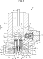
- FIG. 3 is a vertical sectional view of the main part of the pressure boosting pump including a suction valve of the first embodiment
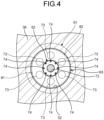
- FIG. 4 is a IV-IV sectional view of FIG. 3 representing the suction valve
- FIG. 5 is a perspective view of a casing pressing member.
- the pressure boosting pump 32 includes a suction valve 41 and a discharge valve 42.
- the suction valve 41 when it opens, sucks liquid hydrogen into a compression chamber 43.
- the discharge valve 42 when it opens, discharges high-pressure liquid hydrogen compressed in the compression chamber 43 to the outside.
- the cylinder block 38 is disposed along the vertical direction VD.
- the cylinder block 38 is formed with a fitting hole 51 opening upward in its upper part and is formed with a recess 52 opening downward in its lower part.
- the fitting hole 51 and the recess 52 have a cylindrical shape and are caused to communicate with each other via a communicating hole 53, which also has a cylindrical shape.
- the piston 37 fits into the fitting hole 51 of the cylinder block 38 from above and is movably supported along the vertical direction VD. By the piston 37 fitting into the fitting hole 51 of the cylinder block 38, the compression chamber 43 sectioned by the piston 37 and the fitting hole 51 is formed.
- the fitting hole 51, the recess 52, the communicating hole 53, the piston 37, and the compression chamber 43 are disposed concentrically.
- the suction valve 41 is disposed in the recess 52 of the cylinder block 38.
- the suction valve 41 has a valve casing 61, a first valve body 62, a second valve body 63, and a pressing member 64.
- the valve casing 61 has a convex cylindrical shape.
- the valve casing 61 has a small-diameter main body 61a and a flange part 61b larger in diameter than the main body 61a.
- the valve casing 61 is formed by the flange part 61b integrally provided in the lower part of the main body 61a.
- the recess 52 has a small-diameter hole 52a and a large-diameter hole 52b larger in diameter than the small-diameter hole 52a.
- the recess 52 is formed by the large-diameter hole 52b integrally provided in the lower part of the small-diameter hole 52a.
- the main body 61a fits into the small-diameter hole 52a of the recess 52, and the flange part 61b fits into the large-diameter hole 52b of the recess 52.
- the lower face of the flange part 61b is continuous with the lower face of the cylinder block 38 without any step.
- the length of the main body 61a is shorter than the length of the small-diameter hole 52a, and thus the distal end face of the main body 61a and the bottom face of the small-diameter hole 52a face each other with a gap.
- a first space part 71 is sectioned between the recess 52 of the cylinder block 38 and the valve casing 61.
- the valve casing 61 is provided with a through hole 72 along the vertical direction VD in its central part.
- the valve casing 61 is provided with a plurality of (six in the present embodiment) suction holes (suction channels) 73 along the vertical direction VD closer to its outer periphery in a radial direction, spaced apart from each other in a circumferential direction.
- the valve casing 61 is provided with a plurality of (eight in this embodiment) first discharge holes (first discharge channels) 74 along the vertical direction VD closer to the through hole 72 in the radial direction, spaced apart from each other in the circumferential direction.
- the suction holes 73 suck liquid hydrogen from the outside into the first space part 71.
- the first discharge holes 74 discharge liquid hydrogen or hydrogen gas staying in the first space part 71 to the outside.
- the outside is a portion that is outside the cylinder block 38, is inside the vessel 39 (refer to FIG. 2 ), and is filled with liquid hydrogen at a low-pressure state of about atmospheric pressure to 1 MPaG.
- the first valve body 62 has a rod part 62a and a head part 62b.
- the head part 62b is provided integrally with the upper end of the rod part 62a.
- the rod part 62a is disposed inside the valve casing 61 along the vertical direction VD. That is, in the first valve body 62, the rod part 62a fits into the through hole 72 of the valve casing 61 and is movably supported along an axial direction (the vertical direction VD).
- the head part 62b has a substantially conical trapezoidal shape expanding its diameter upward.
- the flat top face of the head part 62b is a pressure receiving face 62c and the curved lower face of the head part 62b is a seat face 62d.
- the pressure receiving face 62c faces the compression chamber 43.
- the upper part of the communicating hole 53 expands its diameter upward to form a shape similar to that of the head part 62b and is provided with a valve seat 53a.
- the head part 62b is disposed in the upper part of the communicating hole 53, and the seat face 62d can seat on the valve seat 53a.
- the first valve body 62 moves downward and the seat face 62d of the head part 62b seats on the valve seat 53a, the first valve body 62 closes the communicating hole 53 to isolate the compression chamber 43 and the first space part 71 from each other.
- the first valve body 62 moves upward and the seat face 62d of the head part 62b separates from the valve seat 53a, the first valve body 62 opens the communicating hole 53 to cause the compression chamber 43 and the first space part 71 to communicate with each other.
- the lower end of the rod part 62a protrudes below the valve casing 61.
- a spring receiving member 76 is fixed to its lower end by a nut 75.
- a compression coil spring 77 as a biasing member is disposed between a spring receiving part 61c formed in the valve casing 61 and the spring receiving member 76 of the first valve body 62. The compression coil spring 77 biases the first valve body 62 downward against the valve casing 61.
- the first valve body 62 is biased in the direction in which the seat face 62d of the head part 62b seats on the valve seat 53a of the communicating hole 53 by the biasing force of the compression coil spring 77 and is supported in a biased manner at a position to close the communicating hole 53 and to isolate the compression chamber 43 and the first space part 71 from each other.
- the second valve body 63 is a disk-shaped plate member and is provided with an opening part 63a in its central part.
- the second valve body 63 has an outer diameter approximately the same as the outer diameter of the valve casing 61 and an inner diameter larger than the diameter at the position at which the first discharge holes 74 are formed.
- the second valve body 63 is disposed in the first space part 71 sectioned between the recess 52 of the cylinder block 38 and the valve casing 61.
- the second valve body 63 is movably supported on the cylinder block 38 and the valve casing 61 along the vertical direction VD in the first space part 71. Sealing members 81 and 82 formed in a ring shape are provided between the second valve body 63 and the main body 61a of the valve casing 61.
- the sealing member 81 is disposed closer to the outer periphery of the main body 61a, and the sealing member 82 is disposed closer to the inner periphery of the main body 61a. That is, the sealing members 81 and 82 are disposed on both sides of the main body 61a in the radial direction with the suction holes 73 interposed therebetween.
- its upper face is a pressure receiving face 63b and its lower face is a seat face 63c in contact with the sealing members 81 and 82.
- the pressure receiving face 63b faces the communicating hole 53.
- the first space part 71 and the suction holes 73 are isolated from each other.
- the first space part 71 and the suction holes 73 communicate with each other.
- the pressing member 64 has a cylindrical shape.
- the pressing member 64 presses the valve casing 61 against the cylinder block 38. That is, the pressing member 64 is provided with a plurality of (eight in the present embodiment) mounting holes 91 along the vertical direction VD, spaced apart from each other in the circumferential direction.
- the pressing member 64 its upper face is in contact with the lower face of the cylinder block 38 and the lower face of the flange part 61b of the valve casing 61.
- a plurality of fastening bolts 92 are inserted from below into the respective mounting holes 91 of the pressing member 64, and their tips are threadedly engaged with screw holes of the cylinder block 38.
- the pressing member 64 has an outer diameter approximately the same as the outer diameter of the cylinder block 38 and an inner diameter larger than the diameter of the position at which the suction holes 73 are formed. Thus, lower end openings of the suction holes 73 and lower end openings of the first discharge holes 74 are exposed inside the pressing member 64.
- a plurality of suction tubes 93 are supported on the pressing member 64 via support members not shown. In the suction tubes 93, one ends are coupled to the lower end openings of the suction holes 73, and the other ends are extended upward and open to the outside, that is, the inside of the vessel 39 (refer to FIG. 2 ).
- a second space part 94 is provided inside an inner peripheral face 64a.
- the second space part 94 communicates with the first discharge holes 74 above.
- the second space part 94 communicates with the inside of the vessel 39 (refer to FIG. 2 ), that is, the space filled with liquid hydrogen.
- the liquid hydrogen or hydrogen gas in the first space part 71 is discharged into the liquid hydrogen in the second space part 94 through the first discharge holes 74.
- the pressing member 64 is provided with second discharge holes (second discharge channels) 95 discharging the hydrogen gas discharged from the first space part 71 to the second space part 94 through the first discharge holes 74 outside the pressing member 64 in the radial direction.
- the first discharge holes 74 are disposed along the vertical direction VD, and the second discharge holes 95 are disposed along the horizontal direction.
- One ends of the second discharge holes 95 communicate with the first discharge holes 74 via the second space part 94, and the other ends thereof open to the inside of the vessel 39 (refer to FIG. 2 ), which is the outside.
- a plurality of (eight in the present embodiment) the second discharge holes 95 are provided along the radial direction of the pressing member 64 and spaced apart from each other in the circumferential direction of the pressing member 64.
- the second discharge holes 95 have a slit shape opening upward in the vertical direction VD in the pressing member 64.
- the lower faces of the second discharge holes 95 having a slit shape are along the horizontal direction.
- the discharge valve 42 is a check valve and is disposed on the side of the cylinder block 38.
- the discharge valve 42 has a valve casing 101, a ball 102, a support 103, and a compression coil spring 104.
- the valve casing 101 has a hollow shape and has an inflow hole 101a and a discharge hole 101b.
- the inflow hole 101a communicates with the compression chamber 43, and the discharge hole 101b communicates with a discharge channel for hydrogen gas (not shown).
- the ball 102 can open and close the discharge hole 101b.
- the support 103 supports the ball 102 and transmits the biasing force of the compression coil spring 104 to the ball 102.
- the discharge valve 42 is opened when the pressure of the liquid hydrogen in the compression chamber 43 becomes a preset high pressure or higher. That is, when the pressure of the liquid hydrogen in the compression chamber 43 is less than the high pressure, the ball 102 closes the discharge hole 101b by the biasing force of the compression coil spring 104. On the other hand, when the pressure of the liquid hydrogen in the compression chamber 43 becomes the high pressure or higher, the pressure of the liquid hydrogen becomes higher than the biasing force of the compression coil spring 104, and the ball 102 operates to open the discharge hole 101b.
- FIG. 6 is a vertical sectional view of the main part of the pressure boosting pump including the suction valve of a modification of the first embodiment.
- the pressing member 64 is provided with second discharge holes 96 discharging the hydrogen gas discharged from the first space part 71 to the second space part 94 through the first discharge holes 74 outside the pressing member 64 in the radial direction.
- the second discharge holes 96 are disposed along the horizontal direction. One ends of the second discharge holes 96 communicate with the first discharge holes 74 via the second space part 94, and the other ends thereof open to the inside of the vessel 39 (refer to FIG. 2 ), which is the outside. A plurality of the second discharge holes 96 are provided along the radial direction of the pressing member 64 and spaced apart from each other in the circumferential direction of the pressing member 64. The second discharge holes 96 have a slit shape opening upward in the vertical direction VD in the pressing member 64.
- an end of the pressing member 64 closer to an outer periphery is positioned above an end of the pressing member 64 closer to an inner periphery, in the vertical direction VD of the pressing member 64. That is, in the second discharge holes 96 having a slit shape, their lower faces are inclined, for example, in a range of 5 degrees to 30 degrees with respect to the horizontal direction upward as the distance from the center of the pressing member 64 increases outward.
- FIG. 7 is a vertical sectional view of an operating state of the pressure boosting pump.
- the first valve body 62 moves upward due to its ascending force (suction force) overcoming the biasing force of the compression coil spring 77, and the seat face 62d of the head part 62b separates from the valve seat 53a.
- the first valve body 62 then opens the communicating hole 53, causing the compression chamber 43 and the first space part 71 to communicate with each other.
- the second valve body 63 moves upward due to the negative pressure, and the seat face 63c separates from the sealing members 81 and 82.
- the second valve body 63 then causes the first space part 71 and the suction holes 73 to communicate with each other.
- the suction valve 41 sucks external liquid hydrogen from the respective suction tubes 93 into the first space part 71 through the respective suction holes 73 and further sucks it into the compression chamber 43 through the communicating hole 53.
- the first valve body 62 moves downward by the biasing force of the compression coil spring 77 because the suction force decreases, and the seat face 62d of the head part 62b seats on the valve seat 53a. The first valve body 62 then closes the communicating hole 53, isolating the compression chamber 43 and the first space part 71 from each other.
- the second valve body 63 moves downward because the suction force decreases, and the seat face 63c seats on the sealing members 81 and 82.
- the second valve body 63 then isolates the first space part 71 and the suction holes 73 from each other.
- the pressure in the compression chamber 43 becomes higher pressure because the volume of the compression chamber 43 is further reduced.
- the pressure of the liquid hydrogen in the compression chamber 43 becomes a certain high pressure or higher
- the pressure of the liquid hydrogen becomes higher than the biasing force of the compression coil spring 104
- the ball 102 operates to open the discharge hole 101b.
- the discharge valve 42 discharges the high-pressure liquid hydrogen in the compression chamber 43 to the outside of the cylinder block 38 through the inflow hole 101a and the discharge hole 101b.
- the high-pressure liquid hydrogen having leaked to the first space part 71 is discharged into the liquid hydrogen in the second space part 94, which is at an atmospheric-pressure state, through the first discharge holes 74.
- the high-pressure liquid hydrogen having leaked to the first space part 71 is partly gasified gas (hydrogen gas), which is less likely to be diffused downward and may stay in the second space part 94.
- the second space part 94 communicates with the outside through the second discharge holes 95, and the hydrogen gas staying in the second space part 94 flows horizontally through the second discharge holes 95 and is discharged to the outside of the pressing member 64 closer to its outer periphery.
- the hydrogen gas which has been gasified from the liquid hydrogen staying in the second space part 94, flows diagonally upward through the second discharge holes 96 and is thereby efficiently discharged to the outside of the pressing member 64 closer to its periphery.
- FIG. 8 is a vertical sectional view of the main part of a pressure boosting pump including a suction valve of a second embodiment.
- Components having the same functions as those of the first embodiment described above are denoted by the same symbols, and detailed descriptions thereof will be omitted.
- this pressure boosting pump 32A includes a suction valve 41A and the discharge valve 42.
- the discharge valve 42 is the same as in the first embodiment.
- the suction valve 41A has the valve casing 61, the first valve body 62, the second valve body 63, the pressing member 64, and discharge tubes (third discharge channels) 111.
- the valve casing 61, the first valve body 62, the second valve body 63, and the pressing member 64 are the same as in the first embodiment.
- the valve casing 61 is disposed in the recess 52 of the cylinder block 38, thereby sectioning the first space part 71.
- the valve casing 61 is provided with a through hole 72 in its central part.
- the valve casing 61 is provided with a plurality of suction holes 73 closer to its outer periphery, spaced apart from each other in the circumferential direction.
- the valve casing 61 is provided with a plurality of first discharge holes 74 closer to the through hole 72, spaced apart from each other in the circumferential direction.
- the discharge tubes 111 discharging the hydrogen gas in the first discharge holes 74, below the pressing member 64, are coupled.
- the discharge tube 111 has a vertical part 111a and a horizontal part 111b. To a lower end of the vertical part 111a, one end of the horizontal part 111b is coupled to form an L shape. Lower end openings of the first discharge holes 74 are exposed inside the pressing member 64. A plurality of the discharge tubes 111 are supported on the pressing member 64 via support members not shown.
- upper ends of the vertical parts 111a are coupled to the lower end openings of the first discharge holes 74.
- the other ends of the horizontal parts 111b open to the inside of the vessel 39 (refer to FIG. 2 ).
- the other ends of the horizontal parts 111b may be bent upward to open to the inside of the vessel 39 (refer to FIG. 2 ).
- the liquid hydrogen discharged from the discharge tubes 111 may return to the second space part 94 and stay there.
- the high-pressure liquid hydrogen having leaked to the first space part 71 flows from the first discharge holes 74 to the discharge tubes 111, part of the liquid hydrogen may leak to the second space part 94.
- the high-pressure liquid hydrogen in the second space part 94 flows horizontally through the second discharge holes 95 and is discharged to the outer periphery of the pressing member 64.
- the second discharge holes 95 may be eliminated as needed.
- FIG. 9 is a vertical sectional view of the main part of a pressure boosting pump including a suction valve of a third embodiment.
- Components having the same functions as those of the first embodiment described above are denoted by the same symbols, and detailed descriptions thereof will be omitted.
- this pressure boosting pump 32B includes a suction valve 41B and the discharge valve 42.
- the discharge valve 42 is the same as in the first embodiment.
- the suction valve 41B has the valve casing 61, the first valve body 62, the second valve body 63, and a pressing member 64B.
- the valve casing 61, the first valve body 62, and the second valve body 63 are the same as in the first embodiment.
- the pressing member 64B presses the valve casing 61 against the cylinder block 38.
- the pressing member 64B has a cylindrical shape, and thus the lower end openings of the suction holes 73 and the lower end openings of the first discharge holes 74 are exposed inside. To the suction holes 73, the suction tubes 93 are coupled.
- the pressing member 64B is provided with the second space part 94 inside.
- the second space part 94 communicates with the first discharge holes 74 above.
- the second space part 94 communicates with the inside of the vessel 39 (refer to FIG. 2 ), that is, the space filled with liquid hydrogen.
- the hydrogen gas in the first space part 71 is discharged into the liquid hydrogen in the second space part 94 through the first discharge holes 74.
- the pressing member 64B is provided with second discharge holes (second discharge channels) 97 discharging the hydrogen gas discharged from the first space part 71 to the second space part 94 through the first discharge holes 74 outside the pressing member 64B in the radial direction.
- the first discharge holes 74 are disposed along the vertical direction VD, and the second discharge holes 97 are disposed along the horizontal direction.
- One ends of the second discharge holes 97 communicate with the first discharge holes 74 via the second space part 94, and the other ends thereof open to the inside of the vessel 39 (refer to FIG. 2 ), which is the outside.
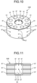
- FIG. 10 is a perspective view of a casing pressing member
- FIG. 11 is a vertical sectional view of the casing pressing member.
- the second discharge holes 97 are provided along the radial direction of the pressing member 64B.
- a plurality of (eight in the present embodiment) the second discharge holes 97 are provided spaced apart from each other in the circumferential direction of the pressing member 64B.
- a plurality of (three in the present embodiment) the second discharge holes 97 are provided spaced apart from each other in an axial direction of the pressing member 64B (the vertical direction VD).
- the second discharge holes 97 are provided unequally spaced or equally spaced in the axial direction of the pressing member 64B (the vertical direction VD).
- the second discharge holes 97 have a hole shape passing through the pressing member 64B in the radial direction.
- the second discharge holes 97 may be positioned such that, as in the modification of the first embodiment, an end of the pressing member 64B closer to an outer periphery is positioned above an end of the pressing member 64B closer to an inner periphery, in the vertical direction VD of the pressing member 64B.
- the second discharge holes 97 having a hole shape may be inclined, for example, in a range of 5 degrees to 30 degrees with respect to the horizontal direction upward as the distance from the center of the pressing member 64B increases outward.
- the operation of the pressure boosting pump 32B of the third embodiment is the same as the operation of the pressure boosting pump 32 of the first embodiment, and thus a description thereof is omitted.
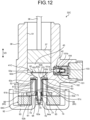
- FIG. 12 is a vertical sectional view of the main part of a pressure boosting pump including a suction valve of a fourth embodiment.
- Components having the same functions as those of the first embodiment described above are denoted by the same symbols, and detailed descriptions thereof will be omitted.
- this pressure boosting pump 32C includes a suction valve 41C and the discharge valve 42.
- the discharge valve 42 is the same as in the first embodiment.
- the suction valve 41C has the valve casing 61, the first valve body 62, the second valve body 63, a pressing member 64C, and a spacer 65.
- the valve casing 61, the first valve body 62, and the second valve body 63 are the same as in the first embodiment.
- the pressing member 64C presses the valve casing 61 against the cylinder block 38.
- the pressing member 64C has a cylindrical shape, and thus the lower end openings of the suction holes 73 and the lower end openings of the first discharge holes 74 are exposed inside. To the suction holes 73, the suction tubes 93 are coupled.
- the pressing member 64C is provided with the second space part 94 inside.
- the second space part 94 communicates with the first discharge holes 74 above.
- the second space part 94 communicates with the inside of the vessel 39 (refer to FIG. 2 ), that is, the space filled with liquid hydrogen.
- the hydrogen gas in the first space part 71 is discharged into the liquid hydrogen in the second space part 94 through the first discharge holes 74.
- the spacer 65 is disposed between the cylinder block 38 and valve casing 61 and the pressing member 64C.
- the spacer 65 is held between the cylinder block 38 and the pressing member 64C and is held between the valve casing 61 and the pressing member 64C.
- the spacer 65 provides second discharge holes (second discharge channels) 98 between the cylinder block 38 and the valve casing 61 and the pressing member 64C.
- the second discharge holes 98 discharge the hydrogen gas discharged from the first space part 71 to the second space part 94 through the first discharge holes 74 outside the pressing member 64C in the radial direction.
- the first discharge holes 74 are disposed along the vertical direction VD, and the second discharge holes 98 are disposed along the horizontal direction.
- One ends of the second discharge holes 98 communicate with the first discharge holes 74 via the second space part 94, and the other ends thereof open to the inside of the vessel 39 (refer to FIG. 2 ), which is the outside.
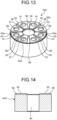
- FIG. 13 is a perspective view of a casing pressing member
- FIG. 14 is a vertical sectional view of the casing pressing member.
- a plurality of (eight in the present embodiment) the spacers 65 are provided spaced apart from each other in the circumferential direction of the pressing member 65C.
- the spacer 65 has a plate shape having a certain thickness.
- the spacer 65 has a fan shape with the apex of the pressing member 65C closer to the center notched in an arc shape in a plan view.
- the spacer 65 has a through hole 65a through which the fastening bolt 92 (refer to FIG. 12 ) passes.
- the spacers 65 are disposed on an upper face of the pressing member 65C along the circumferential direction to form a substantially ring shape in a plan view. Adjacent spacers 65 are disposed spaced apart from each other, thus forming the second discharge holes 98 between the adjacent spacers 65.
- the second discharge holes 98 are formed along the radial direction of the pressing member 64C.
- a plurality of (eight in the present embodiment) the second discharge holes 98 are provided spaced apart from each other in the circumferential direction of the pressing member 64C.
- the second discharge holes 98 have a hole shape along the radial direction sectioned by the spacers 65 between the cylinder block 38 and the valve casing 61 and the pressing member 64C.
- the spacers 65 are disposed independently of each other, but this configuration is not limiting.
- the spacers 65 may be coupled to each other in a ring shape via coupling parts thinner than the spacers 65.
- the operation of the pressure boosting pump 32C of the fourth embodiment is the same as the operation of the pressure boosting pump 32 of the first embodiment, and thus a description thereof is omitted.
- a suction valve includes the cylinder block 38 having the compression chamber 43 and the recess 52 communicating with the compression chamber 43, the valve casing 61 housed in the recess 52 and forming the first space part 71 communicating with the compression chamber 43, the pressing member 64, 64B, or 64C pressing the valve casing 61 against the cylinder block 38, the suction holes (the suction channels) 73 provided in the valve casing 61 and sucking liquid hydrogen (a low-temperature fluid) to the first space part 71, the first discharge holes (the first discharge channels) 74 provided in the valve casing 61 and discharging hydrogen gas in the first space part 71, the first valve body 62 capable of causing the compression chamber 43 and the first space part 71 to communicate with each other and capable of isolating the compression chamber 43 and the first space part 71 from each other, the second valve body 63 capable of causing the first space part 71 and the first discharge holes 74 to communicate with each other and capable of isolating the first space part 71 and the
- the suction valve when high-pressure liquid hydrogen compressed in the compression chamber 43 is discharged outside, part of the high-pressure liquid hydrogen in the compression chamber 43 leaks to the first space part 71, and the high-pressure liquid hydrogen having leaked to the first space part 71 is discharged outside the pressing member 64, 64B, or 64C through the first discharge holes 74 and the second discharge holes 95.
- the high-pressure liquid hydrogen contains vaporized hydrogen gas and is less likely to flow downward but easily flows in the horizontal direction through the second discharge holes 95, and the backflow of the hydrogen gas can be prevented to properly discharge the gasified liquid hydrogen.
- a suction valve according to a second aspect is the suction valve according to the first aspect, in which the first discharge holes 74 are disposed along the vertical direction VD, and the second discharge holes 95, 96, 97, or 98 are disposed along the horizontal direction, one ends of which communicate with the first discharge holes 74 and the other ends of which open outside.
- This configuration allows the vaporized hydrogen gas to flow in the horizontal direction through the second discharge holes 95, and the gasified liquid hydrogen can properly be discharged outside.
- a suction valve according to a third aspect is the suction valve according to the second aspect, in which the pressing member 64, 64B, or 65C has a tubular shape with the second space part 94 formed inside, and one ends of the second discharge holes 95, 96, 97, or 98 communicate with the first discharge holes 74 through the second space part 94.
- the high-pressure liquid hydrogen having leaked to the first space part 71 flows from the first discharge holes 74 to the second space part 94 and is discharged from the second space part 94 outside the pressing member 64, 64B, or 64C through the second discharge holes 95.
- This can eliminate direct connection between the first discharge holes 74 and the second discharge holes 95 to simply the structure.
- a suction valve according to a fourth aspect is the suction valve according to any one of the first aspect to the third aspect, in which the second discharge holes 95, 96, 97, or 98 are provided along the radial direction of the pressing member 64, 64B, or 65C and spaced apart from each other in the circumferential direction of the pressing member 64, 64B, or 65C. With this configuration, the hydrogen gas in the first discharge holes 74 can properly be discharged outside the pressing member 64, 64B, or 64C through the second discharge holes 95.
- a suction valve according to a fifth aspect is the suction valve according to any one of the first aspect to the fourth aspect, in which the second discharge holes 95 or 96 have a slit shape opening upward in the vertical direction VD in the pressing member 64. This configuration enables the second discharge holes 95 or 96 to be easily formed in the pressing member 64, thus improving processability.
- a suction valve according to a sixth aspect is the suction valve according to any one of the first aspect to the fourth aspect, in which the second discharge holes 97 have a hole shape passing through the pressing member 64B in the radial direction. This configuration enables the second discharge holes 97 to be properly formed while inhibiting a reduction in the strength of the pressing member 64B.
- a suction valve according to a seventh aspect is the suction valve according to any one of the first aspect to the sixth aspect, in which in the second discharge holes 96, an end of the pressing member 64 closer to an outer periphery is positioned above an end of the pressing member 64, 64B, or 65C closer to an inner periphery, in the vertical direction VD of the pressing member 64.
- the hydrogen gas in the first discharge holes 74 flows diagonally upward through the second discharge holes 96, and thus the hydrogen gas can efficiently be discharged to the outside of the pressing member 64 closer to its outer periphery.
- a suction valve according to an eighth aspect is the suction valve according to any one of the first aspect to the fourth aspect, in which the second discharge holes 98 are provided between the cylinder block 38 or the valve casing 61 and the pressing member 65C. This configuration eliminates the need to process the second discharge holes 98 in the pressing member 65C, can prevent a reduction in the strength of the pressing member 64B, and can reduce processing costs.
- a suction valve according to a ninth aspect is the suction valve according to any one of the first aspect to the seventh aspect, further including the discharge tubes (the third discharge tubes) 111 discharging the gas in the first discharge holes 74, below the pressing member 64, 64B, or 65C. This configuration can properly discharge the gasified liquid hydrogen.
- a pressure boosting pump includes the suction valve 41, 41A, 41B, or 41C according to any one of the first aspect to the ninth aspect, the piston 37 compressing the liquid hydrogen sucked from the suction valve 41, 41A, 41B, or 41C to the compression chamber 43, and the discharge valve 42 discharging the liquid hydrogen compressed by the piston 37.
- the backflow of the hydrogen gas in the suction valve 41, 41A, 41B, or 41C can be prevented to properly discharge the gasified liquid hydrogen, and consequently, pump efficiency can be improved.
- a hydrogen supply system includes the compression device 21 having the pressure boosting pump 32, 32A, 32B, or 32C of the 10th aspect to compress liquid hydrogen as the low-temperature fluid, the evaporation device 22 vaporizing the liquid hydrogen compressed by the compression device 21, and the dispenser 23 supplying hydrogen gas vaporized by the evaporation device 22.
- This configuration improves the pump efficiency of the pressure boosting pump 32, 32A, 32B, or 32C and can thereby improve the efficiency of supplying the hydrogen gas.
Landscapes
- Engineering & Computer Science (AREA)
- General Engineering & Computer Science (AREA)
- Mechanical Engineering (AREA)
- Reciprocating Pumps (AREA)
- Lift Valve (AREA)
- Check Valves (AREA)
- Fuel Cell (AREA)
- Compressor (AREA)
Abstract
Description
- The present disclosure relates to a suction valve of a pressure boosting pump for boosting the pressure of low-temperature fluids such as hydrogen, a pressure boosting pump having the suction valve, and a hydrogen supply system having the pressure boosting pump.
- Examples of conventional suction valves of pressure boosting pumps include one described in Patent Literature 1 below. The suction valve described in Patent Literature 1 includes a valve casing having a fluid inflow hole and a communicating hole causing a recess and the outside to communicate with each other, a first valve body that can shut off a communicating state between a compression chamber and the recess, and a second valve body that can shut off a communicating state between the recess and the fluid inflow hole while maintaining a communicating state between the recess and the communicating hole. With this suction valve, in a compression stroke of a low-temperature fluid, a compressed fluid in the compression chamber can be discharged to the outside, and the gasified low-temperature fluid remaining in the recess can be discharged to the outside from the communicating hole.
- Patent Literature 1:
Japanese Patent No. 1041807 - Conventional suction valves, when the low-temperature is compressed, can discharge the gasified low-temperature fluid remaining in the recess to the outside from the communicating hole. In this case, the gasified low-temperature fluid remaining in the recess flows downward through the communicating hole extending downward from the recess and is discharged to the outside. However, since the gasified low-temperature fluid is gas, it is less likely to flow downward and may stay around an outlet end of the communicating hole, that is, a lower end of the communicating hole. There is a problem in that if the gasified low-temperature fluid is not properly discharged, the gasified low-temperature fluid is sucked into the compression chamber again in a suction stroke of the low-temperature fluid, resulting in a reduction in the pump efficiency of a pressure boosting pump.
- The present disclosure solves the problem described above, and an object thereof is to provide a suction valve, a pressure boosting pump, and a hydrogen supply system that can properly discharge a gasified fluid.
- In order to achieve the above object, a suction valve according to the present disclosure includes: a block that includes a compression chamber and a recess communicating with the compression chamber; a valve casing that is housed in the recess and forms a first space part communicating with the compression chamber; a pressing member that presses the valve casing against the block; a suction channel that is provided in the valve casing and sucks a low-temperature fluid to the first space part; a first discharge channel that is provided in the valve casing and discharges gas in the first space part; a first valve body that is capable of causing the compression chamber and the first space part to communicate with each other and is capable of isolating the compression chamber and the first space part from each other; a second valve body that is capable of causing the first space part and the first discharge channel to communicate with each other and is capable of isolating the first space part and the first discharge channel from each other; and a second discharge channel that discharges gas in the first discharge channel outside the pressing member.
- Further, a pressure boosting pump according to the present disclosure includes: the above-described suction valve; a piston that compresses the low-temperature fluid sucked from the suction valve to the compression chamber; and a discharge valve that discharges the low-temperature fluid compressed by the piston.
- Further, a hydrogen supply system according to the present disclosure includes: a compression device that includes the above-described pressure boosting pump to compress liquid hydrogen as the low-temperature fluid; an evaporation device that vaporizes the liquid hydrogen compressed by the compression device; and a dispenser that supplies hydrogen gas vaporized by the evaporation device.
- The suction valve, the pressure boosting pump, and the hydrogen supply system of the present disclosure can properly discharge a gasified fluid.
-
-
FIG. 1 is a schematic diagram of an overall configuration of a hydrogen supply system of a first embodiment. -
FIG. 2 is a schematic configuration diagram of a compression device. -
FIG. 3 is a vertical sectional view of the main part of a pressure boosting pump including a suction valve of the first embodiment. -
FIG. 4 is a IV-IV sectional view ofFIG. 3 representing the suction valve. -
FIG. 5 is a perspective view of a casing pressing member. -
FIG. 6 is a vertical sectional view of the main part of the pressure boosting pump including the suction valve of a modification of the first embodiment. -
FIG. 7 is a vertical sectional view of an operating state of the pressure boosting pump. -
FIG. 8 is a vertical sectional view of the main part of a pressure boosting pump including a suction valve of a second embodiment. -
FIG. 9 is a vertical sectional view of the main part of a pressure boosting pump including a suction valve of a third embodiment. -
FIG. 10 is a perspective view of a casing pressing member. -
FIG. 11 is a vertical sectional view of the casing pressing member. -
FIG. 12 is a vertical sectional view of the main part of a pressure boosting pump including a suction valve of a fourth embodiment. -
FIG. 13 is a perspective view of a casing pressing member. -
FIG. 14 is a vertical sectional view of the casing pressing member. - The following describes a preferred embodiment of the present disclosure in detail with reference to the accompanying drawings. The present disclosure is not limited by this embodiment, and when there are a plurality of embodiments, combinations of the embodiments are also included. The components in the embodiment include ones that those skilled in the art can easily assume, substantially the same ones, and ones in what is called the range of equivalence.
-
FIG. 1 is a schematic diagram of an overall configuration of a hydrogen supply system of a first embodiment. - As illustrated in
FIG. 1 , thishydrogen supply system 10 supplies (refills) liquid hydrogen stored in acontainer 11 as hydrogen gas at a certain pressure to a power source of avehicle 12. The power source is, for example, a fuel cell, a hydrogen engine, or the like and is installed in thevehicle 12. Thehydrogen supply system 10 is, for example, what is called a hydrogen station facility supplying (refilling) hydrogen gas as a fuel to the power source of thevehicle 12. However, thehydrogen supply system 10 is not limited to the one supplying hydrogen gas to the power source of thevehicle 12 but also compresses and supplies low-temperature fluids (for example, liquid hydrogen, liquid nitrogen, liquid oxygen, liquefied carbon dioxide gas, liquefied natural gas, liquefied propane gas, and the like). - The
hydrogen supply system 10 has a compression device 21, an evaporation device 22, and a dispenser 23. The compression device 21 compresses liquid hydrogen (a low-temperature fluid) supplied from thecontainer 11 to a certain high pressure (a high-pressure state) set in advance. The evaporation device 22 vaporizes the high-pressure liquid hydrogen compressed by the compression device 21 to generate hydrogen gas. The dispenser 23 fills the power source of thevehicle 12 with the hydrogen gas generated by the evaporation device 22. - The compression device 21 compresses the liquid hydrogen stored in the
container 11 to a certain high pressure, but this is not limiting. For example, if thecontainer 11 stores hydrogen gas, the compression device 21 may compress the hydrogen gas stored in thecontainer 11 to a certain high pressure. - The compression device 21 has a
drive motor 31 and apressure boosting pump 32. Thedrive motor 31 is an electric motor that can be driven by externally supplied electric power. The number of revolutions of thedrive motor 31 is controlled by an inverter (not shown). Thedrive motor 31 transmits rotational power to thepressure boosting pump 32. Thepressure boosting pump 32 operates by the rotational power of thedrive motor 31. -
FIG. 2 is a schematic diagram of the compression device. - As illustrated in
FIG. 2 , thepressure boosting pump 32 is coupled to thedrive motor 31 via a reducer 33. The reducer 33 reduces the rotational power of thedrive motor 31 and transmits it to thepressure boosting pump 32. Thepressure boosting pump 32 is a reciprocating pump. Thepressure boosting pump 32 operates by converting the rotational power of thedrive motor 31, which has been reduced by the reducer 33, into reciprocating power. Thepressure boosting pump 32 alternately performs suction and compression (pressure boosting) of liquid hydrogen by reciprocating power to compress the sucked liquid hydrogen to a certain high-pressure state and discharges it to the outside. - The
pressure boosting pump 32 has acrank mechanism 34, acrosshead 35, apiston rod 36, apiston 37, and acylinder block 38. - The
crank mechanism 34 converts the rotational power transmitted from the reducer 33 into linear reciprocating power and transmits it to thecrosshead 35. Thecrosshead 35 reciprocates in a vertical direction VD by the reciprocating power in the vertical direction VD transmitted from thecrank mechanism 34. Thepiston rod 36 is coupled to thecrosshead 35 at its upper end, and thepiston 37 is coupled to its other end. Thecylinder block 38 has a hollow shape, and thepiston 37 is movably supported along the vertical direction VD thereinside. - The lower part of the
pressure boosting pump 32, that is, thecylinder block 38 is disposed inside avessel 39. Thevessel 39 is an adiabatic vacuum vessel, and its inside is maintained at a vacuum state together with thepressure boosting pump 32. Thevessel 39 is supplied with liquid hydrogen thereinside and filled to an atmospheric-pressure state. - When the
pressure boosting pump 32 is operated, first, at a suction step, at which thepiston 37 ascends, the liquid hydrogen from thevessel 39 is sucked into thecylinder block 38. Next, at a compression step, at which thepiston 37 descends, the liquid hydrogen inside thecylinder block 38 is compressed, and high-pressure liquid hydrogen is discharged to the outside of thevessel 39. -
FIG. 3 is a vertical sectional view of the main part of the pressure boosting pump including a suction valve of the first embodiment,FIG. 4 is a IV-IV sectional view ofFIG. 3 representing the suction valve, andFIG. 5 is a perspective view of a casing pressing member. - As illustrated in
FIG. 3 , thepressure boosting pump 32 includes asuction valve 41 and adischarge valve 42. Thesuction valve 41, when it opens, sucks liquid hydrogen into acompression chamber 43. Thedischarge valve 42, when it opens, discharges high-pressure liquid hydrogen compressed in thecompression chamber 43 to the outside. - The
cylinder block 38 is disposed along the vertical direction VD. Thecylinder block 38 is formed with afitting hole 51 opening upward in its upper part and is formed with arecess 52 opening downward in its lower part. Thefitting hole 51 and therecess 52 have a cylindrical shape and are caused to communicate with each other via a communicatinghole 53, which also has a cylindrical shape. Thepiston 37 fits into thefitting hole 51 of thecylinder block 38 from above and is movably supported along the vertical direction VD. By thepiston 37 fitting into thefitting hole 51 of thecylinder block 38, thecompression chamber 43 sectioned by thepiston 37 and thefitting hole 51 is formed. Thefitting hole 51, therecess 52, the communicatinghole 53, thepiston 37, and thecompression chamber 43 are disposed concentrically. - As illustrated in
FIG. 3 andFIG. 4 , thesuction valve 41 is disposed in therecess 52 of thecylinder block 38. Thesuction valve 41 has avalve casing 61, afirst valve body 62, asecond valve body 63, and a pressingmember 64. - The
valve casing 61 has a convex cylindrical shape. Thevalve casing 61 has a small-diametermain body 61a and aflange part 61b larger in diameter than themain body 61a. Thevalve casing 61 is formed by theflange part 61b integrally provided in the lower part of themain body 61a. Therecess 52 has a small-diameter hole 52a and a large-diameter hole 52b larger in diameter than the small-diameter hole 52a. Therecess 52 is formed by the large-diameter hole 52b integrally provided in the lower part of the small-diameter hole 52a. In thevalve casing 61, themain body 61a fits into the small-diameter hole 52a of therecess 52, and theflange part 61b fits into the large-diameter hole 52b of therecess 52. In this case, in thevalve casing 61, the lower face of theflange part 61b is continuous with the lower face of thecylinder block 38 without any step. In thevalve casing 61, the length of themain body 61a is shorter than the length of the small-diameter hole 52a, and thus the distal end face of themain body 61a and the bottom face of the small-diameter hole 52a face each other with a gap. Thus, afirst space part 71 is sectioned between therecess 52 of thecylinder block 38 and thevalve casing 61. - The
valve casing 61 is provided with a throughhole 72 along the vertical direction VD in its central part. Thevalve casing 61 is provided with a plurality of (six in the present embodiment) suction holes (suction channels) 73 along the vertical direction VD closer to its outer periphery in a radial direction, spaced apart from each other in a circumferential direction. In addition, thevalve casing 61 is provided with a plurality of (eight in this embodiment) first discharge holes (first discharge channels) 74 along the vertical direction VD closer to the throughhole 72 in the radial direction, spaced apart from each other in the circumferential direction. The suction holes 73 suck liquid hydrogen from the outside into thefirst space part 71. The first discharge holes 74 discharge liquid hydrogen or hydrogen gas staying in thefirst space part 71 to the outside. The outside is a portion that is outside thecylinder block 38, is inside the vessel 39 (refer toFIG. 2 ), and is filled with liquid hydrogen at a low-pressure state of about atmospheric pressure to 1 MPaG. - The
first valve body 62 has arod part 62a and ahead part 62b. In thefirst valve body 62, thehead part 62b is provided integrally with the upper end of therod part 62a. Therod part 62a is disposed inside thevalve casing 61 along the vertical direction VD. That is, in thefirst valve body 62, therod part 62a fits into the throughhole 72 of thevalve casing 61 and is movably supported along an axial direction (the vertical direction VD). Thehead part 62b has a substantially conical trapezoidal shape expanding its diameter upward. In thefirst valve body 62, the flat top face of thehead part 62b is apressure receiving face 62c and the curved lower face of thehead part 62b is aseat face 62d. In thefirst valve body 62, thepressure receiving face 62c faces thecompression chamber 43. - In the
cylinder block 38, the upper part of the communicatinghole 53 expands its diameter upward to form a shape similar to that of thehead part 62b and is provided with avalve seat 53a. In thefirst valve body 62, thehead part 62b is disposed in the upper part of the communicatinghole 53, and theseat face 62d can seat on thevalve seat 53a. When thefirst valve body 62 moves downward and theseat face 62d of thehead part 62b seats on thevalve seat 53a, thefirst valve body 62 closes the communicatinghole 53 to isolate thecompression chamber 43 and thefirst space part 71 from each other. On the other hand, when thefirst valve body 62 moves upward and theseat face 62d of thehead part 62b separates from thevalve seat 53a, thefirst valve body 62 opens the communicatinghole 53 to cause thecompression chamber 43 and thefirst space part 71 to communicate with each other. - In the
first valve body 62, the lower end of therod part 62a protrudes below thevalve casing 61. In therod part 62a, aspring receiving member 76 is fixed to its lower end by anut 75. Acompression coil spring 77 as a biasing member is disposed between aspring receiving part 61c formed in thevalve casing 61 and thespring receiving member 76 of thefirst valve body 62. Thecompression coil spring 77 biases thefirst valve body 62 downward against thevalve casing 61. That is, thefirst valve body 62 is biased in the direction in which theseat face 62d of thehead part 62b seats on thevalve seat 53a of the communicatinghole 53 by the biasing force of thecompression coil spring 77 and is supported in a biased manner at a position to close the communicatinghole 53 and to isolate thecompression chamber 43 and thefirst space part 71 from each other. - The
second valve body 63 is a disk-shaped plate member and is provided with anopening part 63a in its central part. Thesecond valve body 63 has an outer diameter approximately the same as the outer diameter of thevalve casing 61 and an inner diameter larger than the diameter at the position at which the first discharge holes 74 are formed. Thesecond valve body 63 is disposed in thefirst space part 71 sectioned between therecess 52 of thecylinder block 38 and thevalve casing 61. Thesecond valve body 63 is movably supported on thecylinder block 38 and thevalve casing 61 along the vertical direction VD in thefirst space part 71.Sealing members second valve body 63 and themain body 61a of thevalve casing 61. The sealingmember 81 is disposed closer to the outer periphery of themain body 61a, and the sealingmember 82 is disposed closer to the inner periphery of themain body 61a. That is, the sealingmembers main body 61a in the radial direction with the suction holes 73 interposed therebetween. In thesecond valve body 63, its upper face is apressure receiving face 63b and its lower face is aseat face 63c in contact with the sealingmembers second valve body 63, thepressure receiving face 63b faces the communicatinghole 53. In thesecond valve body 63, when theseat face 63c seats on the sealingmembers first space part 71 and the suction holes 73 are isolated from each other. On the other hand, in thesecond valve body 63, when theseat face 63c separates from the sealingmembers first space part 71 and the suction holes 73 communicate with each other. - As illustrated in
FIG. 3 andFIG. 5 , the pressingmember 64 has a cylindrical shape. The pressingmember 64 presses thevalve casing 61 against thecylinder block 38. That is, the pressingmember 64 is provided with a plurality of (eight in the present embodiment) mountingholes 91 along the vertical direction VD, spaced apart from each other in the circumferential direction. In the pressingmember 64, its upper face is in contact with the lower face of thecylinder block 38 and the lower face of theflange part 61b of thevalve casing 61. In this state, a plurality offastening bolts 92 are inserted from below into the respective mountingholes 91 of the pressingmember 64, and their tips are threadedly engaged with screw holes of thecylinder block 38. By the pressingmember 64 being fastened to thecylinder block 38, thevalve casing 61 is pressed against the pressingmember 64 while being disposed in therecess 52 and is supported on thecylinder block 38. - The pressing
member 64 has an outer diameter approximately the same as the outer diameter of thecylinder block 38 and an inner diameter larger than the diameter of the position at which the suction holes 73 are formed. Thus, lower end openings of the suction holes 73 and lower end openings of the first discharge holes 74 are exposed inside the pressingmember 64. A plurality ofsuction tubes 93 are supported on the pressingmember 64 via support members not shown. In thesuction tubes 93, one ends are coupled to the lower end openings of the suction holes 73, and the other ends are extended upward and open to the outside, that is, the inside of the vessel 39 (refer toFIG. 2 ). - Since the pressing
member 64 has a cylindrical shape, asecond space part 94 is provided inside an innerperipheral face 64a. Thesecond space part 94 communicates with the first discharge holes 74 above. Thesecond space part 94 communicates with the inside of the vessel 39 (refer toFIG. 2 ), that is, the space filled with liquid hydrogen. Thus, the liquid hydrogen or hydrogen gas in thefirst space part 71 is discharged into the liquid hydrogen in thesecond space part 94 through the first discharge holes 74. - However, the hydrogen gas discharged from the
first space part 71 to thesecond space part 94 through the first discharge holes 74 is gas, is thus less likely to be diffused into the liquid hydrogen, and is likely to stay in thesecond space part 94. Thus, the pressingmember 64 is provided with second discharge holes (second discharge channels) 95 discharging the hydrogen gas discharged from thefirst space part 71 to thesecond space part 94 through the first discharge holes 74 outside the pressingmember 64 in the radial direction. - The first discharge holes 74 are disposed along the vertical direction VD, and the second discharge holes 95 are disposed along the horizontal direction. One ends of the second discharge holes 95 communicate with the first discharge holes 74 via the
second space part 94, and the other ends thereof open to the inside of the vessel 39 (refer toFIG. 2 ), which is the outside. A plurality of (eight in the present embodiment) the second discharge holes 95 are provided along the radial direction of the pressingmember 64 and spaced apart from each other in the circumferential direction of the pressingmember 64. The second discharge holes 95 have a slit shape opening upward in the vertical direction VD in the pressingmember 64. The lower faces of the second discharge holes 95 having a slit shape are along the horizontal direction. - As illustrated in
FIG. 3 , thedischarge valve 42 is a check valve and is disposed on the side of thecylinder block 38. Thedischarge valve 42 has avalve casing 101, aball 102, asupport 103, and acompression coil spring 104. - The
valve casing 101 has a hollow shape and has aninflow hole 101a and adischarge hole 101b. Theinflow hole 101a communicates with thecompression chamber 43, and thedischarge hole 101b communicates with a discharge channel for hydrogen gas (not shown). Theball 102 can open and close thedischarge hole 101b. Thesupport 103 supports theball 102 and transmits the biasing force of thecompression coil spring 104 to theball 102. - The
discharge valve 42 is opened when the pressure of the liquid hydrogen in thecompression chamber 43 becomes a preset high pressure or higher. That is, when the pressure of the liquid hydrogen in thecompression chamber 43 is less than the high pressure, theball 102 closes thedischarge hole 101b by the biasing force of thecompression coil spring 104. On the other hand, when the pressure of the liquid hydrogen in thecompression chamber 43 becomes the high pressure or higher, the pressure of the liquid hydrogen becomes higher than the biasing force of thecompression coil spring 104, and theball 102 operates to open thedischarge hole 101b. - The configuration of the second discharge holes 95 of the
suction valve 41 is not limited to that described above.FIG. 6 is a vertical sectional view of the main part of the pressure boosting pump including the suction valve of a modification of the first embodiment. - As illustrated in
FIG. 6 , the pressingmember 64 is provided with second discharge holes 96 discharging the hydrogen gas discharged from thefirst space part 71 to thesecond space part 94 through the first discharge holes 74 outside the pressingmember 64 in the radial direction. - The second discharge holes 96 are disposed along the horizontal direction. One ends of the second discharge holes 96 communicate with the first discharge holes 74 via the
second space part 94, and the other ends thereof open to the inside of the vessel 39 (refer toFIG. 2 ), which is the outside. A plurality of the second discharge holes 96 are provided along the radial direction of the pressingmember 64 and spaced apart from each other in the circumferential direction of the pressingmember 64. The second discharge holes 96 have a slit shape opening upward in the vertical direction VD in the pressingmember 64. In this case, in the second discharge holes 96 having a slit shape, an end of the pressingmember 64 closer to an outer periphery is positioned above an end of the pressingmember 64 closer to an inner periphery, in the vertical direction VD of the pressingmember 64. That is, in the second discharge holes 96 having a slit shape, their lower faces are inclined, for example, in a range of 5 degrees to 30 degrees with respect to the horizontal direction upward as the distance from the center of the pressingmember 64 increases outward. -
FIG. 7 is a vertical sectional view of an operating state of the pressure boosting pump. - As illustrated in
FIG. 7 , first, at the suction step of thepressure boosting pump 32, when thepiston 37 moves (ascends) from the bottom dead center to the top dead center via thepiston rod 36, the volume of thecompression chamber 43 expands, and thereby the pressure in thecompression chamber 43 becomes negative. In this process, thefirst valve body 62 moves upward due to its ascending force (suction force) overcoming the biasing force of thecompression coil spring 77, and theseat face 62d of thehead part 62b separates from thevalve seat 53a. Thefirst valve body 62 then opens the communicatinghole 53, causing thecompression chamber 43 and thefirst space part 71 to communicate with each other. When the negative pressure in thecompression chamber 43 acts on thesecond valve body 63 through the communicatinghole 53, thesecond valve body 63 moves upward due to the negative pressure, and theseat face 63c separates from the sealingmembers second valve body 63 then causes thefirst space part 71 and the suction holes 73 to communicate with each other. Thus, thesuction valve 41 sucks external liquid hydrogen from therespective suction tubes 93 into thefirst space part 71 through the respective suction holes 73 and further sucks it into thecompression chamber 43 through the communicatinghole 53. - Next, at the compression step of the
pressure boosting pump 32, when thepiston 37 moves (descends) to the upper dead center or the lower dead center via thepiston rod 36, the volume of thecompression chamber 43 is reduced, and thereby the pressure in thecompression chamber 43 becomes positive pressure. In this process, thefirst valve body 62 moves downward by the biasing force of thecompression coil spring 77 because the suction force decreases, and theseat face 62d of thehead part 62b seats on thevalve seat 53a. Thefirst valve body 62 then closes the communicatinghole 53, isolating thecompression chamber 43 and thefirst space part 71 from each other. When the positive pressure in thecompression chamber 43 acts on thesecond valve body 63 through the communicatinghole 53, thesecond valve body 63 moves downward because the suction force decreases, and theseat face 63c seats on the sealingmembers second valve body 63 then isolates thefirst space part 71 and the suction holes 73 from each other. - When the
piston 37 further descends, the pressure in thecompression chamber 43 becomes higher pressure because the volume of thecompression chamber 43 is further reduced. In this process, when the pressure of the liquid hydrogen in thecompression chamber 43 becomes a certain high pressure or higher, the pressure of the liquid hydrogen becomes higher than the biasing force of thecompression coil spring 104, and theball 102 operates to open thedischarge hole 101b. Thus, thedischarge valve 42 discharges the high-pressure liquid hydrogen in thecompression chamber 43 to the outside of thecylinder block 38 through theinflow hole 101a and thedischarge hole 101b. - At the compression step of the
pressure boosting pump 32, while thefirst valve body 62 descends and theseat face 62d of thehead part 62b seats on thevalve seat 53a to close the communicatinghole 53, part of the high-pressure liquid hydrogen in thecompression chamber 43 leaks through the communicatinghole 53 to thefirst space part 71. The high-pressure liquid hydrogen having leaked to thefirst space part 71 is discharged into the liquid hydrogen in thesecond space part 94, which is at an atmospheric-pressure state, through the first discharge holes 74. However, the high-pressure liquid hydrogen having leaked to thefirst space part 71 is partly gasified gas (hydrogen gas), which is less likely to be diffused downward and may stay in thesecond space part 94. However, thesecond space part 94 communicates with the outside through the second discharge holes 95, and the hydrogen gas staying in thesecond space part 94 flows horizontally through the second discharge holes 95 and is discharged to the outside of the pressingmember 64 closer to its outer periphery. In this process, if the second discharge holes 96 are inclined upward outward as illustrated inFIG. 6 , the hydrogen gas, which has been gasified from the liquid hydrogen staying in thesecond space part 94, flows diagonally upward through the second discharge holes 96 and is thereby efficiently discharged to the outside of the pressingmember 64 closer to its periphery. -
FIG. 8 is a vertical sectional view of the main part of a pressure boosting pump including a suction valve of a second embodiment. Components having the same functions as those of the first embodiment described above are denoted by the same symbols, and detailed descriptions thereof will be omitted. - As illustrated in
FIG. 8 , thispressure boosting pump 32A includes asuction valve 41A and thedischarge valve 42. Thedischarge valve 42 is the same as in the first embodiment. Thesuction valve 41A has thevalve casing 61, thefirst valve body 62, thesecond valve body 63, the pressingmember 64, and discharge tubes (third discharge channels) 111. Thevalve casing 61, thefirst valve body 62, thesecond valve body 63, and the pressingmember 64 are the same as in the first embodiment. - The
valve casing 61 is disposed in therecess 52 of thecylinder block 38, thereby sectioning thefirst space part 71. Thevalve casing 61 is provided with a throughhole 72 in its central part. Thevalve casing 61 is provided with a plurality of suction holes 73 closer to its outer periphery, spaced apart from each other in the circumferential direction. Thevalve casing 61 is provided with a plurality of first discharge holes 74 closer to the throughhole 72, spaced apart from each other in the circumferential direction. - In the
valve casing 61, thedischarge tubes 111 discharging the hydrogen gas in the first discharge holes 74, below the pressingmember 64, are coupled. Thedischarge tube 111 has avertical part 111a and ahorizontal part 111b. To a lower end of thevertical part 111a, one end of thehorizontal part 111b is coupled to form an L shape. Lower end openings of the first discharge holes 74 are exposed inside the pressingmember 64. A plurality of thedischarge tubes 111 are supported on the pressingmember 64 via support members not shown. In thedischarge tubes 111, upper ends of thevertical parts 111a are coupled to the lower end openings of the first discharge holes 74. In thedischarge tubes 111, the other ends of thehorizontal parts 111b open to the inside of the vessel 39 (refer toFIG. 2 ). The other ends of thehorizontal parts 111b may be bent upward to open to the inside of the vessel 39 (refer toFIG. 2 ). - Thus, at the compression step of the
pressure boosting pump 32A, when thefirst valve body 62 descends to close the communicatinghole 53, part of the high-pressure liquid hydrogen in thecompression chamber 43 leaks through the communicatinghole 53 to thefirst space part 71. The high-pressure liquid hydrogen containing hydrogen gas having leaked to thefirst space part 71 descends through the first discharge holes 74 and flows to thedischarge tubes 111. The high-pressure liquid hydrogen having flowed to thedischarge tubes 111 is discharged into the liquid hydrogen in the vessel 29, which is at an atmospheric-pressure state, through thevertical parts 111a and thehorizontal parts 111b. - When the high-pressure liquid hydrogen having leaked to the
first space part 71 is discharged from the first discharge holes 74 through thedischarge tubes 111, the liquid hydrogen discharged from thedischarge tubes 111 may return to thesecond space part 94 and stay there. When the high-pressure liquid hydrogen having leaked to thefirst space part 71 flows from the first discharge holes 74 to thedischarge tubes 111, part of the liquid hydrogen may leak to thesecond space part 94. In this case, the high-pressure liquid hydrogen in thesecond space part 94 flows horizontally through the second discharge holes 95 and is discharged to the outer periphery of the pressingmember 64. However, the second discharge holes 95 may be eliminated as needed. -
FIG. 9 is a vertical sectional view of the main part of a pressure boosting pump including a suction valve of a third embodiment. Components having the same functions as those of the first embodiment described above are denoted by the same symbols, and detailed descriptions thereof will be omitted. - As illustrated in
FIG. 9 , thispressure boosting pump 32B includes asuction valve 41B and thedischarge valve 42. Thedischarge valve 42 is the same as in the first embodiment. Thesuction valve 41B has thevalve casing 61, thefirst valve body 62, thesecond valve body 63, and apressing member 64B. Thevalve casing 61, thefirst valve body 62, and thesecond valve body 63 are the same as in the first embodiment. - The pressing
member 64B presses thevalve casing 61 against thecylinder block 38. The pressingmember 64B has a cylindrical shape, and thus the lower end openings of the suction holes 73 and the lower end openings of the first discharge holes 74 are exposed inside. To the suction holes 73, thesuction tubes 93 are coupled. - The pressing
member 64B is provided with thesecond space part 94 inside. Thesecond space part 94 communicates with the first discharge holes 74 above. Thesecond space part 94 communicates with the inside of the vessel 39 (refer toFIG. 2 ), that is, the space filled with liquid hydrogen. Thus, the hydrogen gas in thefirst space part 71 is discharged into the liquid hydrogen in thesecond space part 94 through the first discharge holes 74. - The pressing
member 64B is provided with second discharge holes (second discharge channels) 97 discharging the hydrogen gas discharged from thefirst space part 71 to thesecond space part 94 through the first discharge holes 74 outside the pressingmember 64B in the radial direction. The first discharge holes 74 are disposed along the vertical direction VD, and the second discharge holes 97 are disposed along the horizontal direction. One ends of the second discharge holes 97 communicate with the first discharge holes 74 via thesecond space part 94, and the other ends thereof open to the inside of the vessel 39 (refer toFIG. 2 ), which is the outside. -
FIG. 10 is a perspective view of a casing pressing member, andFIG. 11 is a vertical sectional view of the casing pressing member. - As illustrated in
FIG. 10 and FIG. 11 , the second discharge holes 97 are provided along the radial direction of thepressing member 64B. A plurality of (eight in the present embodiment) the second discharge holes 97 are provided spaced apart from each other in the circumferential direction of thepressing member 64B. A plurality of (three in the present embodiment) the second discharge holes 97 are provided spaced apart from each other in an axial direction of thepressing member 64B (the vertical direction VD). The second discharge holes 97 are provided unequally spaced or equally spaced in the axial direction of thepressing member 64B (the vertical direction VD). The second discharge holes 97 have a hole shape passing through thepressing member 64B in the radial direction. - The second discharge holes 97 may be positioned such that, as in the modification of the first embodiment, an end of the
pressing member 64B closer to an outer periphery is positioned above an end of thepressing member 64B closer to an inner periphery, in the vertical direction VD of thepressing member 64B. In other words, the second discharge holes 97 having a hole shape may be inclined, for example, in a range of 5 degrees to 30 degrees with respect to the horizontal direction upward as the distance from the center of thepressing member 64B increases outward. - Note that the operation of the
pressure boosting pump 32B of the third embodiment is the same as the operation of thepressure boosting pump 32 of the first embodiment, and thus a description thereof is omitted. -
FIG. 12 is a vertical sectional view of the main part of a pressure boosting pump including a suction valve of a fourth embodiment. Components having the same functions as those of the first embodiment described above are denoted by the same symbols, and detailed descriptions thereof will be omitted. - As illustrated in
FIG. 12 , thispressure boosting pump 32C includes asuction valve 41C and thedischarge valve 42. Thedischarge valve 42 is the same as in the first embodiment. Thesuction valve 41C has thevalve casing 61, thefirst valve body 62, thesecond valve body 63, a pressingmember 64C, and aspacer 65. Thevalve casing 61, thefirst valve body 62, and thesecond valve body 63 are the same as in the first embodiment. - The
pressing member 64C presses thevalve casing 61 against thecylinder block 38. Thepressing member 64C has a cylindrical shape, and thus the lower end openings of the suction holes 73 and the lower end openings of the first discharge holes 74 are exposed inside. To the suction holes 73, thesuction tubes 93 are coupled. - The
pressing member 64C is provided with thesecond space part 94 inside. Thesecond space part 94 communicates with the first discharge holes 74 above. Thesecond space part 94 communicates with the inside of the vessel 39 (refer toFIG. 2 ), that is, the space filled with liquid hydrogen. Thus, the hydrogen gas in thefirst space part 71 is discharged into the liquid hydrogen in thesecond space part 94 through the first discharge holes 74. - The
spacer 65 is disposed between thecylinder block 38 andvalve casing 61 and thepressing member 64C. Thespacer 65 is held between thecylinder block 38 and thepressing member 64C and is held between thevalve casing 61 and thepressing member 64C. Thespacer 65 provides second discharge holes (second discharge channels) 98 between thecylinder block 38 and thevalve casing 61 and thepressing member 64C. The second discharge holes 98 discharge the hydrogen gas discharged from thefirst space part 71 to thesecond space part 94 through the first discharge holes 74 outside the pressingmember 64C in the radial direction. The first discharge holes 74 are disposed along the vertical direction VD, and the second discharge holes 98 are disposed along the horizontal direction. One ends of the second discharge holes 98 communicate with the first discharge holes 74 via thesecond space part 94, and the other ends thereof open to the inside of the vessel 39 (refer toFIG. 2 ), which is the outside. -
FIG. 13 is a perspective view of a casing pressing member, andFIG. 14 is a vertical sectional view of the casing pressing member. - As illustrated in
FIG. 13 and FIG. 14 , a plurality of (eight in the present embodiment) thespacers 65 are provided spaced apart from each other in the circumferential direction of the pressing member 65C. Thespacer 65 has a plate shape having a certain thickness. Thespacer 65 has a fan shape with the apex of the pressing member 65C closer to the center notched in an arc shape in a plan view. Thespacer 65 has a throughhole 65a through which the fastening bolt 92 (refer toFIG. 12 ) passes. Thespacers 65 are disposed on an upper face of the pressing member 65C along the circumferential direction to form a substantially ring shape in a plan view.Adjacent spacers 65 are disposed spaced apart from each other, thus forming the second discharge holes 98 between theadjacent spacers 65. - The second discharge holes 98 are formed along the radial direction of the
pressing member 64C. A plurality of (eight in the present embodiment) the second discharge holes 98 are provided spaced apart from each other in the circumferential direction of thepressing member 64C. The second discharge holes 98 have a hole shape along the radial direction sectioned by thespacers 65 between thecylinder block 38 and thevalve casing 61 and thepressing member 64C. - Note that the
spacers 65 are disposed independently of each other, but this configuration is not limiting. For example, taking the assemblability of thesuction valve 41C into consideration, thespacers 65 may be coupled to each other in a ring shape via coupling parts thinner than thespacers 65. - Note that the operation of the
pressure boosting pump 32C of the fourth embodiment is the same as the operation of thepressure boosting pump 32 of the first embodiment, and thus a description thereof is omitted. - A suction valve according to a first aspect includes the cylinder block 38 having the compression chamber 43 and the recess 52 communicating with the compression chamber 43, the valve casing 61 housed in the recess 52 and forming the first space part 71 communicating with the compression chamber 43, the pressing member 64, 64B, or 64C pressing the valve casing 61 against the cylinder block 38, the suction holes (the suction channels) 73 provided in the valve casing 61 and sucking liquid hydrogen (a low-temperature fluid) to the first space part 71, the first discharge holes (the first discharge channels) 74 provided in the valve casing 61 and discharging hydrogen gas in the first space part 71, the first valve body 62 capable of causing the compression chamber 43 and the first space part 71 to communicate with each other and capable of isolating the compression chamber 43 and the first space part 71 from each other, the second valve body 63 capable of causing the first space part 71 and the first discharge holes 74 to communicate with each other and capable of isolating the first space part 71 and the first discharge holes 74 from each other, and the second discharge holes (the second discharge channels) 95, 96, 97, or 98 discharging hydrogen gas in the first discharge holes 74 outside the pressing member 64, 64B, or 64C.
- With the suction valve according to the first aspect, when high-pressure liquid hydrogen compressed in the
compression chamber 43 is discharged outside, part of the high-pressure liquid hydrogen in thecompression chamber 43 leaks to thefirst space part 71, and the high-pressure liquid hydrogen having leaked to thefirst space part 71 is discharged outside the pressingmember - A suction valve according to a second aspect is the suction valve according to the first aspect, in which the first discharge holes 74 are disposed along the vertical direction VD, and the second discharge holes 95, 96, 97, or 98 are disposed along the horizontal direction, one ends of which communicate with the first discharge holes 74 and the other ends of which open outside. This configuration allows the vaporized hydrogen gas to flow in the horizontal direction through the second discharge holes 95, and the gasified liquid hydrogen can properly be discharged outside.
- A suction valve according to a third aspect is the suction valve according to the second aspect, in which the pressing
member second space part 94 formed inside, and one ends of the second discharge holes 95, 96, 97, or 98 communicate with the first discharge holes 74 through thesecond space part 94. With this configuration, the high-pressure liquid hydrogen having leaked to thefirst space part 71 flows from the first discharge holes 74 to thesecond space part 94 and is discharged from thesecond space part 94 outside the pressingmember - A suction valve according to a fourth aspect is the suction valve according to any one of the first aspect to the third aspect, in which the second discharge holes 95, 96, 97, or 98 are provided along the radial direction of the pressing
member member member - A suction valve according to a fifth aspect is the suction valve according to any one of the first aspect to the fourth aspect, in which the second discharge holes 95 or 96 have a slit shape opening upward in the vertical direction VD in the pressing
member 64. This configuration enables the second discharge holes 95 or 96 to be easily formed in the pressingmember 64, thus improving processability. - A suction valve according to a sixth aspect is the suction valve according to any one of the first aspect to the fourth aspect, in which the second discharge holes 97 have a hole shape passing through the
pressing member 64B in the radial direction. This configuration enables the second discharge holes 97 to be properly formed while inhibiting a reduction in the strength of thepressing member 64B. - A suction valve according to a seventh aspect is the suction valve according to any one of the first aspect to the sixth aspect, in which in the second discharge holes 96, an end of the pressing
member 64 closer to an outer periphery is positioned above an end of the pressingmember member 64. With this configuration, the hydrogen gas in the first discharge holes 74 flows diagonally upward through the second discharge holes 96, and thus the hydrogen gas can efficiently be discharged to the outside of the pressingmember 64 closer to its outer periphery. - A suction valve according to an eighth aspect is the suction valve according to any one of the first aspect to the fourth aspect, in which the second discharge holes 98 are provided between the
cylinder block 38 or thevalve casing 61 and the pressing member 65C. This configuration eliminates the need to process the second discharge holes 98 in the pressing member 65C, can prevent a reduction in the strength of thepressing member 64B, and can reduce processing costs. - A suction valve according to a ninth aspect is the suction valve according to any one of the first aspect to the seventh aspect, further including the discharge tubes (the third discharge tubes) 111 discharging the gas in the first discharge holes 74, below the pressing
member - A pressure boosting pump according to a 10th aspect includes the
suction valve piston 37 compressing the liquid hydrogen sucked from thesuction valve compression chamber 43, and thedischarge valve 42 discharging the liquid hydrogen compressed by thepiston 37. With this configuration, the backflow of the hydrogen gas in thesuction valve - A hydrogen supply system according to an 11th aspect includes the compression device 21 having the
pressure boosting pump pressure boosting pump -
- 10 HYDROGEN SUPPLY SYSTEM
- 11 CONTAINER
- 12 VEHICLE
- 21 COMPRESSION DEVICE
- 22 EVAPORATION DEVICE
- 23 DISPENSER
- 31 DRIVE MOTOR
- 32, 32A, 32B, 32C PRESSURE BOOSTING PUMP
- 33 REDUCER
- 34 CRANK MECHANISM
- 35 CROSSHEAD
- 36 PISTON ROD
- 37 PISTON
- 38 CYLINDER BLOCK
- 39 VESSEL
- 41, 41A, 41B, 41C SUCTION VALVE
- 42 DISCHARGE VALVE
- 43 COMPRESSION CHAMBER
- 51 FITTING HOLE
- 52 RECESS
- 53 COMMUNICATING HOLE
- 61 VALVE CASING
- 62 FIRST VALVE BODY
- 63 SECOND VALVE BODY
- 64, 64B, 65C PRESSING MEMBER
- 65 SPACER
- 71 FIRST SPACE PART
- 72 THROUGH HOLE
- 73 SUCTION HOLE (SUCTION CHANNEL)
- 74 FIRST DISCHARGE HOLE (FIRST DISCHARGE CHANNEL)
- 75 NUT
- 76 SPRING RECEIVING MEMBER
- 77 COMPRESSION COIL SPRING
- 81, 82 SEALING MEMBER
- 91 MOUNTING HOLE
- 92 FASTENING BOLT
- 93 SUCTION TUBE
- 94 SECOND SPACE PART
- 95, 96, 97, 98 SECOND DISCHARGE HOLE (SECOND DISCHARGE CHANNEL)
- 101 VALVE CASING
- 102 BALL
- 103 SUPPORT
- 104 COMPRESSION COIL SPRING
- 111 DISCHARGE TUBE (THIRD DISCHARGE CHANNEL)
Claims (11)
- A suction valve comprising:a block that includes a compression chamber and a recess communicating with the compression chamber;a valve casing that is housed in the recess and forms a first space part communicating with the compression chamber;a pressing member that presses the valve casing against the block;a suction channel that is provided in the valve casing and sucks a low-temperature fluid to the first space part;a first discharge channel that is provided in the valve casing and discharges gas in the first space part;a first valve body that is capable of causing the compression chamber and the first space part to communicate with each other and is capable of isolating the compression chamber and the first space part from each other;a second valve body that is capable of causing the first space part and the first discharge channel to communicate with each other and is capable of isolating the first space part and the first discharge channel from each other; anda second discharge channel that discharges gas in the first discharge channel outside the pressing member.
- The suction valve according to claim 1, whereinthe first discharge channel is disposed along a vertical direction, andthe second discharge channel is disposed along a horizontal direction, one end of which communicates with the first discharge channel and another end of which opens outside.
- The suction valve according to claim 2, whereinthe pressing member has a tubular shape with a second space part formed inside, andone end of the second discharge channel communicates with the first discharge channel via the second space part.
- The suction valve according to any one of claims 1 to 3, wherein a plurality of the second discharge channels are provided along a radial direction of the pressing member and spaced apart in a circumferential direction of the pressing member.
- The suction valve according to claim 1, wherein the second discharge channel has a slit shape opening upward in a vertical direction in the pressing member.
- The suction valve according to claim 1, wherein the second discharge channel has a hole shape passing through the pressing member in a radial direction.
- The suction valve according to claim 5 or claim 6, wherein in the second discharge channel, an end of the pressing member closer to an outer periphery is positioned above an end of the pressing member closer to an inner periphery, in a vertical direction of the pressing member.
- The suction valve according to claim 1, wherein the second discharge channel is provided between the block or the valve casing and the pressing member.
- The suction valve according to claim 1, further comprising a third discharge channel that discharges gas in the first discharge channel below the pressing member.
- A pressure boosting pump comprising:the suction valve according to claim 1;a piston that compresses the low-temperature fluid sucked from the suction valve to the compression chamber; anda discharge valve that discharges the low-temperature fluid compressed by the piston.
- A hydrogen supply system comprising:a compression device that includes the pressure boosting pump according to claim 10 to compress liquid hydrogen as the low-temperature fluid;an evaporation device that vaporizes the liquid hydrogen compressed by the compression device; anda dispenser that supplies hydrogen gas vaporized by the evaporation device.
Applications Claiming Priority (2)
| Application Number | Priority Date | Filing Date | Title |
|---|---|---|---|
| JP2022090215A JP7653390B2 (en) | 2022-06-02 | 2022-06-02 | Intake valve, booster pump and hydrogen supply system |
| PCT/JP2023/015237 WO2023233841A1 (en) | 2022-06-02 | 2023-04-14 | Suction valve, boost pump, and hydrogen supply system |
Publications (2)
| Publication Number | Publication Date |
|---|---|
| EP4517143A1 true EP4517143A1 (en) | 2025-03-05 |
| EP4517143A4 EP4517143A4 (en) | 2025-06-11 |
Family
ID=89026202
Family Applications (1)
| Application Number | Title | Priority Date | Filing Date |
|---|---|---|---|
| EP23815602.0A Pending EP4517143A4 (en) | 2022-06-02 | 2023-04-14 | Suction valve, boost pump, and hydrogen supply system |
Country Status (4)
| Country | Link |
|---|---|
| EP (1) | EP4517143A4 (en) |
| JP (1) | JP7653390B2 (en) |
| KR (1) | KR20250004867A (en) |
| WO (1) | WO2023233841A1 (en) |
Family Cites Families (7)
| Publication number | Priority date | Publication date | Assignee | Title |
|---|---|---|---|---|
| JPH1041807A (en) | 1996-04-19 | 1998-02-13 | Texas Instr Inc <Ti> | Optimization of operating characteristics of CMOS integrated circuit |
| JP4146419B2 (en) | 2004-12-17 | 2008-09-10 | 三菱重工業株式会社 | Low temperature liquefied gas pressure pump |
| JP4801409B2 (en) * | 2005-10-06 | 2011-10-26 | 三菱重工業株式会社 | Booster pump for cryogenic fluid |
| JP4031807B2 (en) | 2006-05-12 | 2008-01-09 | 三菱重工業株式会社 | Booster pump for cryogenic fluid |
| JP2010043708A (en) | 2008-08-13 | 2010-02-25 | Mitsubishi Heavy Ind Ltd | Regional energy supply system |
| JP4918605B2 (en) | 2010-06-02 | 2012-04-18 | 三菱重工業株式会社 | Booster pump for cryogenic fluid |
| DE102018206331A1 (en) * | 2018-04-25 | 2019-10-31 | Robert Bosch Gmbh | Fuel delivery device for cryogenic fuels |
-
2022
- 2022-06-02 JP JP2022090215A patent/JP7653390B2/en active Active
-
2023
- 2023-04-14 EP EP23815602.0A patent/EP4517143A4/en active Pending
- 2023-04-14 WO PCT/JP2023/015237 patent/WO2023233841A1/en not_active Ceased
- 2023-04-14 KR KR1020247039261A patent/KR20250004867A/en active Pending
Also Published As
| Publication number | Publication date |
|---|---|
| JP2023177499A (en) | 2023-12-14 |
| KR20250004867A (en) | 2025-01-08 |
| JP7653390B2 (en) | 2025-03-28 |
| EP4517143A4 (en) | 2025-06-11 |
| WO2023233841A1 (en) | 2023-12-07 |
Similar Documents
| Publication | Publication Date | Title |
|---|---|---|
| US20230085780A1 (en) | Compression apparatus and filling station comprising such an apparatus | |
| US12092098B2 (en) | Compression apparatus and filling station comprising such an apparatus | |
| US20230080231A1 (en) | Compression apparatus and filling station comprising such an apparatus | |
| JP2011179341A (en) | Two-stage compression type different diameter piston compressor | |
| US6622612B2 (en) | Pump, particularly plunger pump | |
| EP1767783B1 (en) | Booster pump and storage tank for low-temperature fluid comprising same | |
| US20060198740A1 (en) | Diaphragm pump | |
| EP4534877A1 (en) | Discharge valve, boosting pump, and hydrogen delivery system | |
| JP7653390B2 (en) | Intake valve, booster pump and hydrogen supply system | |
| JP7671889B1 (en) | Boost Pump and Fluid Supply System | |
| JP7713922B2 (en) | Booster pump and hydrogen supply system | |
| JP2005330926A (en) | Reciprocating compressor | |
| US11873802B2 (en) | Pump having multi-stage gas compression | |
| JP2007303406A (en) | Booster pump for low temperature fluid | |
| KR20260066789A (en) | Booster pump and low-temperature fluid supply system, method of discharging low-temperature fluid in a booster pump | |
| JP2025121745A (en) | Discharge valve, booster pump, and hydrogen supply system | |
| JP7720372B2 (en) | Boost pump and cryogenic fluid supply system | |
| US519225A (en) | Washinqton | |
| US20260028972A1 (en) | Reciprocating pump | |
| CN221526293U (en) | Liquid hydrogen pump mounting structure for hydrogen storage tank | |
| KR101559807B1 (en) | Concentric valve assembly for air compressor | |
| WO2025234183A1 (en) | Compression device and low-temperature liquid supply system | |
| KR20260065948A (en) | Boost pump and low-temperature fluid supply system | |
| KR20250095928A (en) | Cryogenic fluid piston pump system | |
| KR200365486Y1 (en) | hand-powered air pump |
Legal Events
| Date | Code | Title | Description |
|---|---|---|---|
| STAA | Information on the status of an ep patent application or granted ep patent |
Free format text: STATUS: THE INTERNATIONAL PUBLICATION HAS BEEN MADE |
|
| PUAI | Public reference made under article 153(3) epc to a published international application that has entered the european phase |
Free format text: ORIGINAL CODE: 0009012 |
|
| STAA | Information on the status of an ep patent application or granted ep patent |
Free format text: STATUS: REQUEST FOR EXAMINATION WAS MADE |
|
| 17P | Request for examination filed |
Effective date: 20241128 |
|
| AK | Designated contracting states |
Kind code of ref document: A1 Designated state(s): AL AT BE BG CH CY CZ DE DK EE ES FI FR GB GR HR HU IE IS IT LI LT LU LV MC ME MK MT NL NO PL PT RO RS SE SI SK SM TR |
|
| XX | Miscellaneous (additional remarks) |
Free format text: A REQUEST FOR CORRECTION OF THE DESCRIPTION HAS BEEN FILED PURSUANT TO RULE 139 EPC. A DECISION ON THE REQUEST WILL BE TAKEN DURING THE PROCEEDINGS BEFORE THE EXAMINING DIVISION (GUIDELINES FOR EXAMINATION IN THE EPO, A-V, 3). |
|
| REG | Reference to a national code |
Ref country code: DE Ref legal event code: R079 Free format text: PREVIOUS MAIN CLASS: F16K0015060000 Ipc: F16K0001440000 |
|
| A4 | Supplementary search report drawn up and despatched |
Effective date: 20250512 |
|
| RIC1 | Information provided on ipc code assigned before grant |
Ipc: F16K 15/06 20060101ALI20250506BHEP Ipc: F16K 15/04 20060101ALI20250506BHEP Ipc: F04B 53/10 20060101ALI20250506BHEP Ipc: F04B 15/08 20060101ALI20250506BHEP Ipc: H01M 8/04 20160101ALI20250506BHEP Ipc: F16K 1/44 20060101AFI20250506BHEP |
|
| DAV | Request for validation of the european patent (deleted) | ||
| DAX | Request for extension of the european patent (deleted) |