EP4517124A1 - Reibpartner für eine trommelbremsvorrichtung mit einer staubsammelanordnung eines fahrzeugs, insbesondere nutzfahrzeugs, trommelbremsvorrichtung, fahrzeug - Google Patents
Reibpartner für eine trommelbremsvorrichtung mit einer staubsammelanordnung eines fahrzeugs, insbesondere nutzfahrzeugs, trommelbremsvorrichtung, fahrzeug Download PDFInfo
- Publication number
- EP4517124A1 EP4517124A1 EP24187282.9A EP24187282A EP4517124A1 EP 4517124 A1 EP4517124 A1 EP 4517124A1 EP 24187282 A EP24187282 A EP 24187282A EP 4517124 A1 EP4517124 A1 EP 4517124A1
- Authority
- EP
- European Patent Office
- Prior art keywords
- brake
- drum
- vehicle
- friction
- brake device
- Prior art date
- Legal status (The legal status is an assumption and is not a legal conclusion. Google has not performed a legal analysis and makes no representation as to the accuracy of the status listed.)
- Withdrawn
Links
Images
Classifications
-
- F—MECHANICAL ENGINEERING; LIGHTING; HEATING; WEAPONS; BLASTING
- F16—ENGINEERING ELEMENTS AND UNITS; GENERAL MEASURES FOR PRODUCING AND MAINTAINING EFFECTIVE FUNCTIONING OF MACHINES OR INSTALLATIONS; THERMAL INSULATION IN GENERAL
- F16D—COUPLINGS FOR TRANSMITTING ROTATION; CLUTCHES; BRAKES
- F16D65/00—Parts or details
- F16D65/02—Braking members; Mounting thereof
- F16D65/10—Drums for externally- or internally-engaging brakes
-
- F—MECHANICAL ENGINEERING; LIGHTING; HEATING; WEAPONS; BLASTING
- F16—ENGINEERING ELEMENTS AND UNITS; GENERAL MEASURES FOR PRODUCING AND MAINTAINING EFFECTIVE FUNCTIONING OF MACHINES OR INSTALLATIONS; THERMAL INSULATION IN GENERAL
- F16D—COUPLINGS FOR TRANSMITTING ROTATION; CLUTCHES; BRAKES
- F16D65/00—Parts or details
- F16D65/02—Braking members; Mounting thereof
- F16D65/04—Bands, shoes or pads; Pivots or supporting members therefor
- F16D65/08—Bands, shoes or pads; Pivots or supporting members therefor for internally-engaging brakes
-
- F—MECHANICAL ENGINEERING; LIGHTING; HEATING; WEAPONS; BLASTING
- F16—ENGINEERING ELEMENTS AND UNITS; GENERAL MEASURES FOR PRODUCING AND MAINTAINING EFFECTIVE FUNCTIONING OF MACHINES OR INSTALLATIONS; THERMAL INSULATION IN GENERAL
- F16D—COUPLINGS FOR TRANSMITTING ROTATION; CLUTCHES; BRAKES
- F16D51/00—Brakes with outwardly-movable braking members co-operating with the inner surface of a drum or the like
- F16D51/16—Brakes with outwardly-movable braking members co-operating with the inner surface of a drum or the like shaped as brake-shoes pivoted on a fixed or nearly-fixed axis
- F16D51/18—Brakes with outwardly-movable braking members co-operating with the inner surface of a drum or the like shaped as brake-shoes pivoted on a fixed or nearly-fixed axis with two brake-shoes
- F16D51/20—Brakes with outwardly-movable braking members co-operating with the inner surface of a drum or the like shaped as brake-shoes pivoted on a fixed or nearly-fixed axis with two brake-shoes extending in opposite directions from their pivots
-
- F—MECHANICAL ENGINEERING; LIGHTING; HEATING; WEAPONS; BLASTING
- F16—ENGINEERING ELEMENTS AND UNITS; GENERAL MEASURES FOR PRODUCING AND MAINTAINING EFFECTIVE FUNCTIONING OF MACHINES OR INSTALLATIONS; THERMAL INSULATION IN GENERAL
- F16D—COUPLINGS FOR TRANSMITTING ROTATION; CLUTCHES; BRAKES
- F16D65/00—Parts or details
-
- F—MECHANICAL ENGINEERING; LIGHTING; HEATING; WEAPONS; BLASTING
- F16—ENGINEERING ELEMENTS AND UNITS; GENERAL MEASURES FOR PRODUCING AND MAINTAINING EFFECTIVE FUNCTIONING OF MACHINES OR INSTALLATIONS; THERMAL INSULATION IN GENERAL
- F16D—COUPLINGS FOR TRANSMITTING ROTATION; CLUTCHES; BRAKES
- F16D65/00—Parts or details
- F16D65/0031—Devices for retaining friction material debris, e.g. dust collectors or filters
-
- F—MECHANICAL ENGINEERING; LIGHTING; HEATING; WEAPONS; BLASTING
- F16—ENGINEERING ELEMENTS AND UNITS; GENERAL MEASURES FOR PRODUCING AND MAINTAINING EFFECTIVE FUNCTIONING OF MACHINES OR INSTALLATIONS; THERMAL INSULATION IN GENERAL
- F16D—COUPLINGS FOR TRANSMITTING ROTATION; CLUTCHES; BRAKES
- F16D69/00—Friction linings; Attachment thereof; Selection of coacting friction substances or surfaces
- F16D2069/004—Profiled friction surfaces, e.g. grooves, dimples
Definitions
- the disclosure relates to a friction partner for a drum brake device with a dust collection arrangement of a vehicle, in particular a commercial vehicle.
- the disclosure also relates to a drum brake device for a vehicle, in particular a commercial vehicle, and to a vehicle, in particular a commercial vehicle.
- vehicle in particular commercial vehicle, is hereinafter also referred to as vehicle.
- Drum brakes of the type described above are well known and are used in vehicles as friction brakes to slow down the movement of the vehicle.
- Friction brakes work on the principle of friction. Brake pads are brought into friction with a brake drum in order to generate a braking effect on the vehicle. The friction between the brake pads and the brake drum causes abrasion on the friction materials of the brake pads and on the brake drum, the brake dust, also known as friction particles, brake dust particles and/or brake particles.
- Brake dust particles are dust particles with a size of, for example, less than 10 ⁇ m, so-called fine dust, which can be classified as hazardous to health and harmful to the environment due to its small particle size and chemical composition. The release of fine dust into the environment is therefore not desired. It is therefore in the general interest to design disc brakes in such a way that the release of fine dust generated during braking into the environment is prevented as far as possible.
- DE 10 2021 204 132 A1 discloses a drum brake for a motor vehicle, which comprises a brake drum and an anchor plate.
- the brake drum and the anchor plate form a housing, wherein between the anchor plate and the At least one air gap is formed in the brake drum.
- a magnetic ring surrounds an outer circumferential side of the housing, wherein the magnetic ring is aligned with the air gap in such a way that a particle stream with brake particles from an interior of the housing strikes a magnetic field of the magnetic ring.
- DE 4 036 908 A1 discloses a groove design. In order to reduce the temperature and abrasion when operating friction linings, it is proposed to provide these linings with grooves which are designed in such a way that they run from the front edge of the friction lining in a continuously tapering manner approximately in the direction of rotation.
- DE 196 48 908 A1 discloses a brake drum for a drum brake with a friction surface running around the brake drum axis, wherein the friction surface is provided with at least one groove which has a self-contained groove profile and which extends over the entire extent of the friction surface in the circumferential direction.
- EP 0 486 772 B1 discloses a groove design. In order to reduce the temperature and abrasion when operating friction linings, it is proposed to provide these linings with grooves which are designed in such a way that they run from the front edge of the friction lining in a continuously tapering manner approximately in the direction of rotation.
- the aim is to avoid releasing brake particles that arise from friction and thus from wear into the environment while the vehicle is in operation.
- the disclosure is based on the object of enriching the prior art and improving aspects of the prior art.
- the disclosure solves the problem of enabling effective and simple collection of brake particles from a drum brake.
- a friction partner for a drum brake device with a dust collection arrangement of a vehicle, in particular a commercial vehicle; wherein the friction partner has a friction body for contacting a second friction body of a second friction partner; the friction body has a structured recess arrangement; and the recess arrangement is configured to generate an air flow for the directed transport of brake particles to the dust collection arrangement during a relative rotational movement of the friction partner with respect to the second friction partner.
- a dust collection arrangement can be provided to prevent the brake particles from accumulating in the brake drum and at the same time to prevent them from being emitted into the environment and to collect and/or specifically remove the brake particles. It was also recognized that an air flow or fluid flow can be induced that can direct the brake particles and lead them to the dust collection arrangement.
- a specific recess arrangement or groove geometry is provided, similar to the technology of hydrodynamic air bearings and/or spiral groove bearings, in particular so-called herringbone bearings.
- the groove geometry of such a bearing generates an air flow that makes it possible for a rotor to lift off at sufficient rotation (lift-off speed) and run on an air buffer. This means that a directed fluid flow is generated by a rotational movement, which results in a pressure with which the Rotor is supported.
- This basic idea is applied to a drum brake according to the disclosure.
- the core of the disclosure is therefore to apply a geometry as a structured recess arrangement to the friction surface of the friction partner in order to generate a fluid flow within the brake drum during a relative rotational movement between the friction partner and the second friction partner.
- the fluid flow within the drum brake ensures that the brake particles can be guided to the collection arrangement.
- the recess arrangement comprises a plurality of spiral grooves arranged off-center.
- a spiral groove refers to a groove or recess that is at least partially spiral-shaped, i.e. a recess with a curvature that changes along its contour.
- the spiral groove winds around an assumed spiral center point.
- the off-center arrangement of the spiral groove means that the assumed spiral center point is arranged outside the friction body. It was recognized that the spiral groove geometry can be applied off-center in order to be able to direct the fluid flow in a desired pumping direction and to ensure that the brake particles are not directed to the friction body and thus clog the recess arrangement. This can support the conduction of the fluid flow and thus the brake particles into the dust collection arrangement.
- the drum brake device defines an axis
- the recess arrangement comprises a plurality of grooves inclined relative to the axis.
- the grooves can be straight and/or curved.
- the axis can be the axis of rotation of a brake drum of the drum brake device.
- the fluid flow can be generated by the inclination of the grooves relative to the axis.
- the friction partner is a brake pad. It was recognized that it is possible to incorporate the structured recess arrangement into the brake pad as one of the friction partners.
- a brake drum rotates and thus generates a relative rotational movement between the brake pad and the brake drum, which can generate the air flow.
- the recess arrangement has a depth that corresponds at least to the thickness of the brake pad.
- the thickness of the brake pad is the radial extension of the friction body.
- the thickness of the brake pad is smaller than the radial extension of the friction body and defines the possible and/or permitted material removal due to wear of the brake pad.
- the depth of the recess arrangement can be in the range of 1 to 5 mm in order to allow wear of the brake pad, whereby the air flow can be generated despite the wear.
- the friction partner is a brake drum. It was recognized that it is possible to incorporate the structured recess arrangement into the brake drum as one of the friction partners.
- the brake drum rotates and thus generates a relative rotational movement between a brake pad and the brake drum, which can generate the air flow.
- the recess arrangement has a depth of up to 0.5 cm. It was recognized that a comparatively small depth can be sufficient, since the material removal from the brake drum caused by wear is typically less than that from the brake pads.
- a drum brake device for a vehicle, in particular a commercial vehicle.
- the drum brake device comprises a friction partner described above, a second friction partner and a dust collection arrangement.
- the friction partner can have one or more of the features described above as optional and/or advantageous in order to produce an associated technical effect.
- the drum brake device has an anchor plate and a circumferential seal for sealing a brake drum against the anchor plate, and the seal and/or the anchor plate has at least one ventilation opening. It was recognized that targeted ventilation through the ventilation arrangement can improve the air flow, its generation and its steering.
- the seal and/or the anchor plate and the dust collection arrangement are static components of the drum brake device.
- the arrangement of the ventilation opening and the dust collection arrangement can thus define how the air flow for transporting the brake particles to the dust collection device must run. The arrangement can therefore define requirements for the geometry of the recess arrangement.
- the brake drum is sealed against the anchor plate with a circumferential seal.
- Ventilation openings are arranged in the seal and/or the anchor plate, for example with an extension of 3 cm each in the circumferential direction. Air can be sucked in through the ventilation openings. The openings and the resulting fluid flow also have a cooling effect. Thermal stress can be a problem with drum brakes, especially encapsulated ones, and can be reduced by ventilation.
- the at least one ventilation opening is arranged in an upper region of the drum brake device in the assembled state; the dust collection arrangement is arranged in a lower region of the drum brake device in the assembled state; and the dust collection arrangement is arranged such that brake particles are conveyed to the dust collection arrangement by the air flow.
- the ventilation opening can be arranged in the upper half of the brake drum so that the dust collection arrangement can be arranged on the underside.
- the brake particles can be fed into the dust collection arrangement by gravity and collected there and/or discharged in a collected manner.
- a vehicle in particular a commercial vehicle, comprising the drum brake device described above is provided.
- the drum brake device can have one or more of the above have features described as optional and/or advantageous in order to produce an associated technical effect.
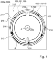
- FIG. 1 shows a schematic representation of a vehicle 200a, in particular commercial vehicle 200b, according to one aspect of the disclosure.
- vehicle 200a in particular commercial vehicle 200b
- vehicle 200a, 200b is referred to below as vehicle 200a, 200b.
- the vehicle 200a, 200b is a land vehicle, for example a towing vehicle and/or a trailer vehicle of a multi-unit vehicle, a single-unit vehicle and/or a bus.
- the representation of the vehicle 200a, 200b is limited to the components essential to the disclosure, whereby it should be understood that the vehicle 200a, 200b has, in addition to the components shown, other components required for the operation of the vehicle 200a, 200b, such as a drive train, a chassis and/or a body.
- the representation of such components has been omitted in favor of a reproduction of the disclosure.
- the vehicle 200a, 200b has a drum brake device 210 for decelerating the movement of the vehicle 200a, 200b.
- the vehicle 200a, 200b optionally has a pneumatic system (not shown) that is configured to apply compressed air to the optionally pneumatic and/or electropneumatic drum brake device 210 for actuating the drum brake device 210.
- the drum brake device 210 can be actuated hydraulically and/or electromechanically.
- the drum brake device 210 comprises a friction partner 100, a second friction partner 110, a dust collection arrangement 220, an anchor plate 103 and a circumferential seal 215.
- the friction partner 100 is one of two brake pads 101 and the second friction partner 110 is a brake drum 102.
- the friction partner 100 is the brake drum and the second friction partner 110 is one of two brake pads 101.
- the brake drum 102 is designed to have a cross-indexed and in Figure 1 to rotate about the axis A projecting into the image plane.
- the brake drum 102 is arranged on a wheel hub 205 so that it can rotate about the axis A.
- the brake pads 101 are arranged so that they cannot rotate.
- the brake pads 101 are arranged so that they cannot rotate on the anchor plate 103 and can be moved for actuation. Therefore, when the vehicle 200a, 200b moves, the brake drum 102 rotates and thus a relative rotational movement R occurs between the brake drum 102 and the brake pads 101.
- the drum brake device 210 is designed to press the brake pads 101 against the brake drum 102 when actuated in order to achieve a braking effect by contacting the brake pads 101 with the brake drum 102, i.e. contacting the friction partners 100, 101. In this process, brake particles 120 are released from the brake pads 101 and the brake drum 102.
- the drum brake device 210 For collecting and optionally removing brake particles 120, the drum brake device 210 has the dust collection arrangement 220.
- the dust collection arrangement 220 is arranged in a rotationally fixed or stationary manner within the brake drum 102.
- the dust collection arrangement 220 is attached to the anchor plate 103.
- the seal 215 is arranged circumferentially and is designed to press the brake drum 102 against the anchor plate 103 in order to prevent brake particles 120 from escaping between the brake drum 102 and the anchor plate 103.
- the anchor plate 103 and the brake drum 102 can each have a particularly radially outer section with the same radius (in the schematic illustration of the Figure 1 For the sake of illustration only, the brake drum 102 is shown with a smaller radius than the anchor plate 103.
- the seal 215 is arranged between the particularly radially outer section of the brake drum 102 and the anchor plate 103.
- the friction partner 100 has a friction body 105 (see also Figures 3 to 5 ) for contacting a second friction body 115 of the second friction partner 110.
- the friction body 105 of one of the brake pads 101 is the part of the brake pad 101 intended for wear, i.e. a radially outer section of the respective brake pad 101.
- the second friction body 115 of the brake drum 102 is the part of the brake drum 102 intended for contact with the brake pads 101, i.e. a radially inner section of a casing side of the brake drum 102.
- the friction body 105 has a structured recess arrangement 108 (see Figures 2 to 5 ).
- the recess arrangement 108 is designed to generate an air flow F (see arrows with dotted line) for the directed transport of the brake particles 120 to the dust collection arrangement 220 during the relative rotational movement R.
- the dust collection arrangement 220 can be arranged such that the dust collection arrangement 220 protrudes in the radial direction between the brake pads 101 and/or has a branch section for branching off a part of the air flow F that can be guided into the dust collection arrangement 220 (not shown).
- the dust collection arrangement 220 and/or the branch section can optionally in the radial direction between the brake pads 101 and the brake drum 102.
- the structured recess arrangement 108 is an arrangement of recesses that is milled, for example, into the friction body 105.
- the structured recess arrangement 108 is designed to generate and direct the air flow F during the relative rotational movement R.
- the air flow F has a mass flow or volume flow such that it can transport the brake particles 120.
- the seal 215 and/or the anchor plate 103 has a plurality of circumferentially arranged ventilation openings 216. Air can thus be sucked in from an environment of the drum brake device 210 through the ventilation openings 216. The sucked-in air is set in motion by the relative rotational movement R and transports the brake particles 120 to the dust collection arrangement 220.
- the dust collection arrangement 220 can form an outlet for the air flow F from the brake drum 103.
- the air flow F can be filtered in the dust collection arrangement 220 and thus collect the brake particles 120.
- the dust collection arrangement 220 is arranged such that the brake particles 120 are conveyed by the air flow F to the dust collection arrangement 220.
- the ventilation openings 216 are arranged in an upper region 211 of the drum brake device 210 in the assembled state.
- the ventilation openings 216 are arranged on a level with the hub 205 and above, which can counteract an emission of brake particles 120.
- the dust collection arrangement 220 is arranged in a lower region 212 of the drum brake device 210 in the assembled state.
- the dust collection arrangement 220 is arranged below the hub 205, which can promote a gravity-assisted transport of the brake particles 120 to the dust collection arrangement 220.
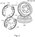
- FIG. 2 shows a perspective view of components of a drum brake device 210 according to an aspect of the disclosure.
- the drum brake device 210 according to Figure 2 is an embodiment of the Figure 1 shown drum brake device 210.
- Figure 2 is made with reference to Figure 1 described.
- the friction partner 100 is the brake drum 102.
- the brake drum 102 has a friction body 105 with a structured recess arrangement 108.
- the recess arrangement 108 has a depth T of up to 0.5 cm.
- the depth T is a distance between a radially inner reference surface of the brake drum 102 and a radially outer section of the brake drum 102 defining the recess arrangement 108.
- the radially inner reference surface is a contact surface at which the friction body 105 of the brake drum 102 contacts the brake pads 101.
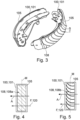
- Figure 3 shows a perspective view of brake pads 101 of a drum brake device 210 according to an aspect of the disclosure.
- the brake pad 101 according to Figure 3 is an alternative embodiment to the Figure 2 shown brake pad 101.
- Figure 3 is made with reference to Figures 1 and 2 described.
- the friction partner 100 is a brake pad 101.
- the brake pad 101 has a friction body 105 with a structured recess arrangement 108.
- the friction body 105 is in particular the part of the brake pad 101 intended for wear.
- the friction body 105 has a thickness S, i.e. a radial dimension of the brake pad 101 in which the brake pad 101 is intended for wear.
- the recess arrangement 108 has a depth T which corresponds at least to the thickness S of the brake pad 101.
- Figure 4 shows a schematic representation of a top view of a brake pad 101 of a drum brake device 210 according to one aspect of the disclosure.
- Figure 4 is a schematic view of the brake pad 101 according to Figure 3.
- Figure 4 is made with reference to Figures 1 to 3 described.
- the drum brake device 210 defines an axis A and the brake pad 101 defines a center M.
- the center M is, for example, an axis of symmetry of the brake pad 101 and is arranged perpendicular to the axis A.
- the recess arrangement 108 comprises a plurality of grooves 108a inclined relative to the axis A and/or relative to the center M.
- the inclination of the grooves 108a defines a pumping direction of the air flow F.
- the grooves 108a can be inclined such that the air flow F is directed away from a front side of the brake drum 103 facing away from the vehicle and/or towards the interior of the brake drum 103. The air flow F can thus be effectively supplied to the dust collection arrangement 220.
- the brake drum 101 may have a friction body 105 with such a recess arrangement 108.
- Figure 5 shows a schematic representation of a top view of a brake pad 101 of a drum brake device 210 according to one aspect of the disclosure.
- the recess arrangement 108 comprises a plurality of off-center spiral grooves 108b.
- the spiral grooves 108b have a changing curvature along their contour, for example along the axis A.
- the spiral grooves 108b as sections of a spiral can be arranged in such a way that the air flow F is directed away from a front side of the brake drum 103 facing away from the vehicle and/or towards the interior of the brake drum 103. The air flow F can thus be effectively fed to the dust collection arrangement 220.
- the brake drum 101 may have a friction body 105 with such a recess arrangement 108.
- both friction bodies 105, 115 or the brake drum 103 and the brake pads 102 have a structured recess arrangement 108 as described with reference to Figures 1 to 5 described.
Landscapes
- Engineering & Computer Science (AREA)
- General Engineering & Computer Science (AREA)
- Mechanical Engineering (AREA)
- Braking Arrangements (AREA)
Abstract
Reibpartner (100) für eine Trommelbremsvorrichtung (210) mit einer Staubsammelanordnung (220) eines Fahrzeugs (200a), insbesondere Nutzfahrzeugs (200b); wobei der Reibpartner (100) einen Reibkörper (105) zum Kontaktieren eines zweiten Reibkörpers (115) eines zweiten Reibpartners (110) aufweist; der Reibkörper (105) eine strukturierte Vertiefungsanordnung (108) aufweist; und die Vertiefungsanordnung (108) dazu eingerichtet ist, bei einer relativen Rotationsbewegung (R) des Reibpartners (100) gegenüber dem zweiten Reibpartners (110) einen Luftstrom (F) zum gerichteten Transport von Bremspartikeln (120) zu der Staubsammelanordnung (220) zu erzeugen.
Description
- Die Offenbarung betrifft einen Reibpartner für eine Trommelbremsvorrichtung mit einer Staubsammelanordnung eines Fahrzeugs, insbesondere Nutzfahrzeugs. Die Offenbarung betrifft auch eine Trommelbremsvorrichtung für ein Fahrzeug, insbesondere Nutzfahrzeug, und ein Fahrzeug, insbesondere Nutzfahrzeug.
- Das Fahrzeug, insbesondere Nutzfahrzeug, wird im Folgenden auch als Fahrzeug bezeichnet.
- Trommelbremsen der vorbezeichneten Art sind bekannt und werden in Fahrzeugen als Reibbremse zum Verzögern der Bewegung des Fahrzeuges eingesetzt. Reibbremsen funktionieren nach dem Reibungsprinzip. Dabei werden Bremsbeläge mit einer Bremstrommel in Reibwirkung gebracht, um eine Bremswirkung auf das Fahrzeug zu erzeugen. Durch die Reibung zwischen den Bremsbelägen und der Bremstrommel entsteht ein Abrieb an den Reibstoffen der Bremsbeläge und an der Bremstrommel, der Bremsstaub, auch Reibpartikel, Bremsstaubpartikel und/oder Bremspartikel genannt. Bremsstaubpartikel sind Staubpartikel in einer Größenordnung von beispielsweise kleiner 10 µm, sogenannter Feinstaub, der aufgrund seiner geringen Partikelgröße und seiner chemischen Zusammensetzung als gesundheitsgefährdend und umweltbelastend eingestuft sein kann. Eine Abgabe des Feinstaubs an die Umwelt ist entsprechend nicht gewünscht. Es ist daher von allgemeinem Interesse, Scheibenbremsen so zu gestalten, dass eine Abgabe des beim Bremsvorgang entstehenden Feinstaubs an die Umwelt möglichst verhindert wird.
- Für Trommelbremsen ist es bekannt, zur besseren Kühlung und auch zum Führen von Bremspartikeln einen Luftstrom zu verwenden.
-
DE 10 2021 204 132 A1 offenbart eine Trommelbremse für ein Kraftfahrzeug, die eine Bremstrommel und eine Ankerplatte umfasst. Die Bremstrommel und die Ankerplatte bilden ein Gehäuse, wobei zwischen der Ankerplatte und der Bremstrommel wenigstens ein Luftspalt ausgebildet ist. Ein Magnetring umringt eine äußere Umfangsseite des Gehäuses, wobei der Magnetring derart zum Luftspalt ausgerichtet ist, dass ein Partikelstrom mit Bremspartikeln aus einem Inneren des Gehäuses auf ein Magnetfeld des Magnetrings trifft. - Das Vorsehen eines Magnetrings ist jedoch aufwändig. Das Sammeln der Bremspartikel durch das Magnetfeld kann nur mit Materialen mit bestimmten magnetischen Eigenschaften erzielt werden und kann somit nur mit geeigneten Bremsbelägen funktionieren.
- Ferner ist es bekannt, über Nuten die Trommelbremse zu Kühlen und/oder ein Abschätzen und/oder ein Beeinflussen des Verschleißes zu erzielen.
-
DE 4 036 908 A1 offenbart eine Nutausbildung. Zur Verringerung der Temperatur und des Abriebs bei der Betätigung von Reibbelägen wird vorgeschlagen, diese Beläge mit Nuten zu versehen, die so ausgebildet sind, dass sie von der Vorderkante des Reibbelages sich stetig verjüngend annähernd in Drehrichtung verlaufen. -
DE 196 48 908 A1 offenbart eine Bremstrommel für eine Trommelbremse mit einer um die Bremstrommelachse verlaufenden Reibfläche, wobei die Reibfläche mit zumindest einer Nut versehen ist, die einen in sich geschlossenen Nutverlauf aufweist und die sich über die gesamte Ausdehnung der Reibfläche in Umfangsrichtung erstreckt. -
EP 0 486 772 B1 offenbart eine Nutausbildung. Zur Verringerung der Temperatur und des Abriebs bei der Betätigung von Reibbelägen wird vorgeschlagen, diese Beläge mit Nuten zu versehen, die so ausgebildet sind, dass sie von der Vorderkante des Reibbelages sich stetig verjüngend annähernd in Drehrichtung verlaufen. - Jedenfalls ist es angestrebt, die bei einem Reiben und somit bei einem Verschleiß anfallenden Bremspartikel möglichst nicht während des Betreibens des Fahrzeugs in die Umwelt zu entlassen.
- Der Offenbarung liegt die Aufgabe zugrunde, den Stand der Technik zu bereichern und Aspekte des Standes der Technik zu verbessern. Insbesondere löst die Offenbarung die Aufgabe, ein effektives und einfaches Sammeln von Bremspartikeln einer Trommelbremse zu ermöglichen.
- Die Aufgabe wird durch ein Verfahren nach Anspruch 1 sowie den Gegenständen nach den weiteren unabhängigen Ansprüchen gelöst. Die Unteransprüche geben Weiterbildungen der Offenbarung an.
- Gemäß einem Aspekt der Offenbarung wird ein Reibpartner für eine Trommelbremsvorrichtung mit einer Staubsammelanordnung eines Fahrzeugs, insbesondere Nutzfahrzeugs, bereitgestellt; wobei der Reibpartner einen Reibkörper zum Kontaktieren eines zweiten Reibkörpers eines zweiten Reibpartners aufweist; der Reibkörper eine strukturierte Vertiefungsanordnung aufweist; und die Vertiefungsanordnung dazu eingerichtet ist, bei einer relativen Rotationsbewegung des Reibpartners gegenüber dem zweiten Reibpartners einen Luftstrom zum gerichteten Transport von Bremspartikeln zu der Staubsammelanordnung zu erzeugen.
- Dabei wurde erkannt, dass eine Staubsammelanordnung bereitgestellt werden kann, um ein Ansammeln der Bremspartikel in der Bremstrommel und gleichzeitig eine Emission in die Umwelt zu vermeiden und um die Bremspartikel sammeln und/oder gezielt abführen zu können. Ferner wurde erkannt, dass ein Luftstrom beziehungsweise Fluidstrom induziert werden kann, der die Bremspartikel gerichtet leiten und zu der Staubsammelanordnung führen kann.
- Dafür wird, ähnlich zu der Technik der hydrodynamischen Luftlager und/oder Spiralrillenlager, insbesondere sogenannter Heringbone-Lager, eine bestimmte Vertiefungsanordnung beziehungsweise Rillengeometrie vorgesehen. Durch die Rillengeometrie wird bei einem derartigen Lager ein Luftstrom erzeugt, der es möglich macht, dass ein Rotor bei ausreichender Umdrehung (Abhebedrehzahl) abhebt und auf einem Luftpuffer läuft. D.h. es wird durch eine Rotationsbewegung ein gerichteter Fluidstrom erzeugt, welcher in einem Druck resultiert, mit dem der Rotor getragen wird. Diese grundsätzliche Idee wird gemäß der Offenbarung für eine Trommelbremse angewendet.
- Kern der Offenbarung ist es daher, als strukturierte Vertiefungsanordnung eine Geometrie auf die Reibfläche des Reibpartners aufzubringen, um bei einer relativen Rotationsbewegung zwischen dem Reibpartner und dem zweiten Reibpartner einen Fluidstrom innerhalb der Bremstrommel zu erzeugen. Der Fluidstrom sorgt innerhalb der Trommelbremse dafür, dass die Bremspartikel zu der Sammelanordnung geleitet werden können.
- Sowohl Magnete als auch eine aktives Saugsystem sind somit entbehrlich. Allein durch den gerichteten Fluidstrom ist es möglich, die Bremspartikel gezielt zu der ortsfesten Staubsammelanordnung zu leiten.
- Optional umfasst die Vertiefungsanordnung eine Mehrzahl von außermittig angeordnete Spiralrillen. Dabei bezeichnet eine Spiralrille eine wenigstens teilweise spiralförmig ausgebildete Rille beziehungsweise Vertiefung, also um eine Vertiefung mit einer sich entlang ihrer Kontur ändernden Krümmung. Die Spiralrille windet sich um einen angenommen Spiralmittelpunkt. Die außermittige Anordnung der Spiralrille bedeutet, dass der angenommene Spiralmittelpunkt außerhalb des Reibkörpers angeordnet ist. Dabei wurde erkannt, dass die Spiralrillengeometrie außermittig aufgebracht werden kann, um den Fluidstrom in eine gewünschte Pumprichtung leiten zu können und um zu gewährleisten, dass die Bremspartikel nicht zu den Reibkörper geleitet werden und die Vertiefungsanordnung so verstopfen. Damit kann die Leitung des Fluidstroms und somit der Bremspartikel in die Staubsammelanordnung unterstützt werden.
- Optional definiert die Trommelbremsvorrichtung eine Achse, und die Vertiefungsanordnung umfasst eine Mehrzahl von gegenüber der Achse geneigter Nuten. Die Nuten können dabei gerade und/oder gekrümmt sein. Die Achse kann dabei die Rotationsachse einer Bremstrommel der Trommelbremsvorrichtung sein. Durch die Neigung der Nuten gegenüber der Achse kann der Fluidstrom erzeugt werden.
- Optional ist der Reibpartner ein Bremsbelag. Dabei wurde erkannt, dass es möglich ist, die strukturierte Vertiefungsanordnung in den Bremsbelag als einen der Reibpartner einzubringen. Beim Fahren rotiert eine Bremstrommel und erzeugt so eine relative Rotationsbewegung zwischen dem Bremsbelag und der Bremstrommel, womit der Luftstrom erzeugt werden kann.
- Optional weist die Vertiefungsanordnung eine Tiefe auf, die wenigstens einer Stärke des Bremsbelags entspricht. Die Stärke des Bremsbelags ist dabei die radiale Ausdehnung des Reibkörpers. Alternativ ist die Stärke des Bremsbelags kleiner als die radiale Ausdehnung des Reibkörpers und definiert den ermöglichten und/oder zugelassenen Materialabtrag durch Verschleiß des Bremsbelags. Beispielsweise kann die Tiefe der Vertiefungsanordnung im Bereich von 1 bis 5 mm liegen, um einen Verschleiß des Bremsbelags zu ermöglichen, wobei trotz des Verschleißes der Luftstrom erzeugt werden kann.
- Optional ist der Reibpartner eine Bremstrommel. Dabei wurde erkannt, dass es möglich ist, die strukturierte Vertiefungsanordnung in die Bremstrommel als einen der Reibpartner einzubringen. Beim Fahren rotiert die Bremstrommel und erzeugt so eine relative Rotationsbewegung zwischen einem Bremsbelag und der Bremstrommel, womit der Luftstrom erzeugt werden kann.
- Optional weist die Vertiefungsanordnung eine Tiefe von bis zu 0,5 cm auf. Dabei wurde erkannt, dass eine vergleichsweise geringe Tiefe ausreichend sein kann, da ein durch den Verschleiß erzeugter Materialabtrag der Bremstrommel typischerweise geringer ist als der der Bremsbeläge.
- Gemäß einem Aspekt der Offenbarung wird eine Trommelbremsvorrichtung für ein Fahrzeug, insbesondere Nutzfahrzeug, bereitgestellt. Die Trommelbremsvorrichtung umfasst einen oben beschriebenen Reibpartner, einen zweiten Reibpartner und eine Staubsammelanordnung. Dabei kann der Reibpartner ein oder mehrere der oben als optional und/oder vorteilhaft beschrieben Merkmale aufweisen, um einen damit verbundenen technischen Effekt zu erzeugen.
- Optional weist die Trommelbremsvorrichtung eine Ankerplatte und eine umlaufende Dichtung zum Abdichten einer Bremstrommel gegen die Ankerplatte auf, und die Dichtung und/oder die Ankerplatte weist mindestens eine Belüftungsöffnung auf. Dabei wurde erkannt, dass durch eine gezielte Belüftung durch die Belüftungsanordnung der Luftstrom, dessen Erzeugung beziehungsweise dessen Lenkung verbessert werden kann. Die Dichtung und/oder die Ankerplatte sowie die Staubsammelanordnung sind statische Bestandteile der Trommelbremsvorrichtung. Die Anordnung der Belüftungsöffnung sowie der Staubsammelanordnung kann somit definieren, wie der Luftstrom zum Transport der Bremspartikel zu der Staubsammelvorrichtung zu verlaufen hat. Somit kann die Anordnung Anforderungen an die Geometrie der Vertiefungsanordnung definieren. Um ein Austreten des Bremsstaubs zu verhindern, ist die Bremstrommel gegen die Ankerplatte mit einer umlaufenden Dichtung abgedichtet. Um trotzdem einen Fluidstrom zu ermöglichen, sind in der Dichtung und/oder der Ankerplatte Belüftungsöffnungen angeordnet, beispielsweise mit einer Ausdehnung von je 3cm im Umfangsrichtung. Durch die Belüftungsöffnungen kann Luft angesaugt werden. Die Öffnungen und der resultierende Fluidstrom haben ebenfalls eine kühlende Wirkung. Thermische Belastung kann bei Trommelbremsen, besonders bei gekapselten, ein Problem sein, und kann durch die Belüftung gemindert werden.
- Optional ist die mindestens eine Belüftungsöffnung in einem im montierten Zustand oberen Bereich der Trommelbremsvorrichtung angeordnet; die Staubsammelanordnung ist in einem im montierten Zustand in einem unteren Bereich der Trommelbremsvorrichtung angeordnet; und die Staubsammelanordnung ist derart angeordnet, dass Bremspartikeln von dem Luftstrom zu der Staubsammelanordnung gefördert werden. Die Belüftungsöffnung kann in der oberen Hälfte der Bremstrommel angeordnet sein, damit auf der Unterseite die Staubsammelanordnung angeordnet werden kann. Die Bremspartikel können schwerkraftgestützt in der Staubsammelanordnung zugeführt und dort gesammelt und/oder gesammelt abgeführt werden.
- Gemäß einem Aspekt der Offenbarung wird ein Fahrzeug, insbesondere Nutzfahrzeug, umfassend die oben beschriebene Trommelbremsvorrichtung bereitgestellt. Dabei kann die Trommelbremsvorrichtung ein oder mehrere der oben als optional und/oder vorteilhaft beschrieben Merkmale aufweisen, um einen damit verbundenen technischen Effekt zu erzeugen.
- Weitere Merkmale der Offenbarung sowie deren technische Effekte ergeben sich aus den Figuren und der Beschreibung der in den Figuren gezeigten bevorzugten Ausführungsformen. Dabei zeigen
- Fig. 1
- eine schematische Darstellung eines Fahrzeugs, insbesondere Nutzfahrzeugs, gemäß einem Aspekt der Offenbarung;
- Fig. 2
- eine perspektivische Darstellung von Komponenten einer Trommelbremsvorrichtung gemäß einem Aspekt der Offenbarung;
- Fig. 3
- eine perspektivische Darstellung von Bremsbelägen einer Trommelbremsvorrichtung gemäß einem Aspekt der Offenbarung;
- Fig. 4
- eine schematische Darstellung einer Draufsicht auf einen Bremsbelag einer Trommelbremsvorrichtung gemäß einem Aspekt der Offenbarung; und
- Fig. 5
- eine schematische Darstellung einer Draufsicht auf einen Bremsbelag einer Trommelbremsvorrichtung gemäß einem Aspekt der Offenbarung.
-
Figur 1 zeigt eine schematische Darstellung eines Fahrzeugs 200a, insbesondere Nutzfahrzeugs 200b, gemäß einem Aspekt der Offenbarung. Das Fahrzeug 200a, insbesondere Nutzfahrzeugs 200b, wird im Folgenden als Fahrzeug 200a, 200b bezeichnet. Das Fahrzeug 200a, 200b ist ein Landfahrzeug, beispielsweise ein Zugfahrzeug und/oder ein Anhängefahrzeug eines mehrgliedrigen Fahrzeugs, ein eingliedriges Fahrzeug und/oder ein Bus. - Die Darstellung des Fahrzeugs 200a, 200b beschränkt sich auf die für die Offenbarung wesentlichen Komponenten, wobei vorliegend verstanden werden soll, dass das Fahrzeug 200a, 200b neben den abgebildeten Komponenten weitere für den Betrieb des Fahrzeugs 200a, 200b erforderliche Komponenten, wie zum Beispiel einen Antriebsstrang, ein Fahrwerk und/oder eine Karosserie, aufweist. Auf die Darstellung derartiger Komponenten ist zugunsten einer Wiedergabe der Offenbarung verzichtet worden.
- Das Fahrzeug 200a, 200b weist eine Trommelbremsvorrichtung 210 zum Verzögern der Bewegung des Fahrzeugs 200a, 200b auf. Das Fahrzeug 200a, 200b weist optional ein pneumatisches System (nicht gezeigt) auf, das dazu eingerichtet, die optional pneumatische und/oder elektropneumatische Trommelbremsvorrichtung 210 zum Aktuieren der Trommelbremsvorrichtung 210 mit Druckluft zu beaufschlagen. Alternativ oder zusätzlich kann die Trommelbremsvorrichtung 210 hydraulisch und/oder elektro-mechanisch aktuierbar sein.
- Die Trommelbremsvorrichtung 210 umfasst einen Reibpartner 100, einen zweiten Reibpartner 110, eine Staubsammelanordnung 220, eine Ankerplatte 103 und eine umlaufende Dichtung 215.
- In der in
Figuren 1 und3 bis 5 ist der Reibpartner 100 einer von zwei Bremsbelägen 101 und der zweite Reibpartner 110 ist eine Bremstrommel 102. In der inFigur 2 gezeigten Ausführungsform ist der Reibpartner 100 die Bremstrommel und der zweite Reibpartner 110 ist einer von zwei Bremsbelägen 101. - Die Bremstrommel 102 ist dazu eingerichtet, um eine mit einem Kreuz indizierte und in
Figur 1 in die Bildebene hineinragende Achse A zu rotieren. Dafür ist die Bremstrommel 102 an einer Radnabe 205 um die Achs A rotierbar angeordnet. Die Bremsbeläge 101 sind rotationsfest angeordnet. Beispielsweise sind die Bremsbeläge 101 an der Ankerplatte 103 rotationsfest und zum Betätigen bewegbar angeordnet. Daher entsteht bei einer Bewegung des Fahrzeugs 200a, 200b eine Rotation der Bremstrommel 102 und somit eine relative Rotationsbewegung R zwischen der Bremstrommel 102 und den Bremsbelägen 101. - Die Trommelbremsvorrichtung 210 ist dazu eingerichtet, bei einer Betätigung die Bremsbeläge 101 gegen die Bremstrommel 102 zu drücken, um so durch eine Kontaktierung der Bremsbeläge 101 mit der Bremstrommel 102, also eine Kontaktierung zwischen den Reibpartnern 100, 101, eine Bremswirkung zu erzielen. Dabei werden Bremspartikel 120 aus den Bremsbelägen 101 und der Bremstrommel 102 herausgelöst.
- Zum Sammeln und optional Abführen Bremspartikel 120 weist die Trommelbremsvorrichtung 210 die Staubsammelanordnung 220 auf. Die Staubsammelanordnung 220 ist rotationsfest beziehungsweise ortsfest innerhalb der Bremstrommel 102 angeordnet. Beispielsweise ist die Staubsammelanordnung 220 an der Ankerplatte 103 befestigt.
- Die Dichtung 215 ist umfänglich angeordnet und dazu eingerichtet, die Bremstrommel 102 gegen die Ankerplatte 103 abzutreten, um zwischen der Bremstrommel 102 und der Ankerplatte 103 ein Austreten von Bremspartikeln 120 zu unterbinden. Dabei können die Ankerplatte 103 und die Bremstrommel 102 jeweils einen insbesondere radial äußeren Abschnitt mit demselben Radius aufweisen (in der schematischen Illustration der
Figur 1 ist nur der Darstellung halber die Bremstrommel 102 mit einem kleineren Radius als die Ankerplatte 103 dargestellt). Die Dichtung 215 ist zwischen den insbesondere radial äußeren Abschnitt der Bremstrommel 102 und der Ankerplatte 103 angeordnet. - Der Reibpartner 100 weist einen Reibkörper 105 (siehe auch
Figuren 3 bis 5 ) zum Kontaktieren eines zweiten Reibkörpers 115 des zweiten Reibpartners 110 auf. Der Reibkörper 105 eines der Bremsbeläge 101 ist dabei der zum Verschleiß vorgesehene Teil des Bremsbelags 101, also ein radial äußerer Abschnitt des jeweiligen Bremsbelags 101. Der zweite Reibkörper 115 der Bremstrommel 102 ist der zum Kontakt mit den Bremsbelägen 101 vorgesehene Teil der Bremstrommel 102, also ein radial innerer Abschnitt einer Mantelseite der Bremstrommel 102. - Der Reibkörper 105 weist eine strukturierte Vertiefungsanordnung 108 (siehe
Figuren 2 bis 5 ) auf. Die Vertiefungsanordnung 108 ist dazu eingerichtet, bei der relativen Rotationsbewegung R einen Luftstrom F (siehe Pfeile mit punktgestrichener Linie) zum gerichteten Transport der Bremspartikeln 120 zu der Staubsammelanordnung 220 zu erzeugen. Dafür kann die Staubsammelanordnung 220 derart angeordnet sein, dass die Staubsammelanordnung 220 in radialer Richtung zwischen die Bremsbeläge 101 ragt und/oder einen Abzweigabschnitt zum Abzweigen eines in die Staubsammelanordnung 220 leitbaren Teils des Luftstrom F aufweist (nicht gezeigt). Dafür kann die Staubsammelanordnung 220 und/oder der Abzweigabschnitt optional in radialer Richtung zwischen die Bremsbeläge 101 und die Bremstrommel 102 ragen. - Die strukturierte Vertiefungsanordnung 108 ist eine Anordnung von Vertiefungen, die beispielsweise in den Reibkörper 105 eingefräst ist. Die strukturierte Vertiefungsanordnung 108 ist dazu eingerichtet, bei der relativen Rotationsbewegung R den Luftstrom F zu erzeugen und zu leiten. Der Luftstrom F weist dabei ein derartigen Massenstrom beziehungsweise Volumenstrom auf, um die Bremspartikel 120 transportieren zu können.
- Die Dichtung 215 und/oder die Ankerplatte 103 weist eine Mehrzahl von umfänglich angeordneten Belüftungsöffnungen 216 auf. Damit kann durch die Belüftungsöffnungen 216 Luft aus einer Umgebung der Trommelbremsvorrichtung 210 angesaugt werden. Die angesaugte Luft wird durch die relative Rotationsbewegung R in Bewegung versetzt und vollzieht den Transport von den Bremspartikel 120 zu der Staubsammelanordnung 220. Die Staubsammelanordnung 220 kann einen Ausgang für den Luftstrom F aus der Bremstrommel 103 bilden. Der Luftstrom F kann in der Staubsammelanordnung 220 gefiltert werden und so die Bremspartikel 120 sammeln. Die Staubsammelanordnung 220 ist derart angeordnet, dass die Bremspartikel 120 von dem Luftstrom F zu der Staubsammelanordnung 220 gefördert werden.
- Die Belüftungsöffnungen 216 sind in einem im montierten Zustand oberen Bereich 211 der Trommelbremsvorrichtung 210 angeordnet. Insbesondere sind die Belüftungsöffnungen 216 auf einer Ebene mit der Nabe 205 und darüber angeordnet, was einer Emission von Bremspartikeln 120 entgegenwirken kann.
- Die Staubsammelanordnung 220 ist in einem im montierten Zustand in einem unteren Bereich 212 der Trommelbremsvorrichtung 210 angeordnet. Insbesondere ist die Staubsammelanordnung 220 unterhalb der Nabe 205 angeordnet, was ein schwerkraftunterstütztes Transportieren der Bremspartikeln 120 zu der Staubsammelanordnung 220 begünstigen kann.
-
Figur 2 zeigt eine perspektivische Darstellung von Komponenten einer Trommelbremsvorrichtung 210 gemäß einem Aspekt der Offenbarung. Die Trommelbremsvorrichtung 210 gemäßFigur 2 ist eine Ausführungsform der inFigur 1 gezeigten Trommelbremsvorrichtung 210.Figur 2 wird unter Bezugnahme aufFigur 1 beschrieben. - Dabei ist der Reibpartner 100 die Bremstrommel 102. Mit anderen Worten weist die Bremstrommel 102 einen Reibkörper 105 mit einer strukturierten Vertiefungsanordnung 108 auf.
- Die Vertiefungsanordnung 108 weist eine Tiefe T von bis zu 0,5 cm auf. Die Tiefe T ist dabei ein Abstand zwischen einer radial inneren Referenzfläche der Bremstrommel 102 und einen die Vertiefungsanordnung 108 definierenden radial äußeren Abschnitt der Bremstrommel 102. Dabei ist die radial innere Referenzfläche eine Kontaktfläche, an der der Reibkörper 105 der Bremstrommel 102 die Bremsbeläge 101 kontaktiert.
-
Figur 3 zeigt eine perspektivische Darstellung von Bremsbelägen 101 einer Trommelbremsvorrichtung 210 gemäß einem Aspekt der Offenbarung. Der Bremsbelag 101 gemäßFigur 3 ist eine alternative Ausführungsform zu den inFigur 2 gezeigten Bremsbelag 101.Figur 3 wird unter Bezugnahme aufFiguren 1 und2 beschrieben. - Der Reibpartner 100 ist ein Bremsbelag 101. Mit anderen Worten weist der Bremsbelag 101 einen Reibkörper 105 mit einer strukturierten Vertiefungsanordnung 108 auf.
- Der Reibkörper 105 ist insbesondere der zum Verschleiß vorgesehene Teil des Bremsbelags 101. Der Reibkörper 105 weist eine Stärke S auf, also eine radiale Abmessung des Bremsbelags 101, in der der Bremsbelag 101 zum Verschleiß vorgesehen ist. Die Vertiefungsanordnung 108 weist eine Tiefe T auf, die wenigstens der Stärke S des Bremsbelags 101 entspricht.
-
Figur 4 zeigt eine schematische Darstellung einer Draufsicht auf einen Bremsbelag 101 einer Trommelbremsvorrichtung 210 gemäß einem Aspekt der Offenbarung.Figur 4 ist eine schematische Ansicht des Bremsbelags 101 gemäßFigur 3. Figur 4 wird unter Bezugnahme aufFiguren 1 bis 3 beschrieben. - Die Trommelbremsvorrichtung 210 definiert eine Achse A und der Bremsbelag 101 definiert eine Mitte M. Die Mitte M ist beispielsweise eine Symmetrieachse des Bremsbelag 101 und senkrecht zu der Achse A angeordnet.
- Die Vertiefungsanordnung 108 umfasst eine Mehrzahl von gegenüber der Achse A und/oder gegenüber der Mitte M geneigter Nuten 108a. Die Neigung der Nuten 108a definiert eine Pumprichtung des Luftstroms F. Die Nuten 108a können derart geneigt werden, dass der Luftstrom F von einer fahrzeugabgewandten Stirnseite der Bremstrommel 103 fort und/oder zum Inneren der Bremstrommel 103 gerichtet ist. Damit kann der Luftstrom F effektiv der Staubsammelanordnung 220 zugeführt werden.
- In einer anderen Ausführungsform kann die Bremstrommel 101 einen Reibkörper 105 mit einer derartigen Vertiefungsanordnung 108 aufweisen.
-
Figur 5 zeigt eine schematische Darstellung einer Draufsicht auf einen Bremsbelag 101 einer Trommelbremsvorrichtung 210 gemäß einem Aspekt der Offenbarung. - Die Vertiefungsanordnung 108 umfasst eine Mehrzahl von außermittig angeordneten Spiralrillen 108b. Die Spiralrillen 108b weisen entlang ihrer Kontur, also beispielsweise entlang der Achse A eine sich ändernde Krümmung auf. Die Spiralrillen 108b als Abschnitte einer Spirale können derart angeordnet werden, dass der Luftstrom F von einer fahrzeugabgewandten Stirnseite der Bremstrommel 103 fort und/oder zum Inneren der Bremstrommel 103 gerichtet ist. Damit kann der Luftstrom F effektiv der Staubsammelanordnung 220 zugeführt werden.
- In einer anderen Ausführungsform kann die Bremstrommel 101 einen Reibkörper 105 mit einer derartigen Vertiefungsanordnung 108 aufweisen.
- In einer weiteren Ausführungsform ist es möglich, dass beide Reibkörper 105, 115 beziehungsweise die Bremstrommel 103 und die Bremsbeläge 102 über eine strukturierte Vertiefungsanordnung 108 wie mit Bezug zu
Figuren 1 bis 5 beschrieben aufweisen. -
- 100
- Reibpartner
- 101
- Bremsbelag
- 102
- Bremstrommel
- 103
- Ankerplatte
- 105
- Reibkörper
- 108
- Vertiefungsanordnung
- 108a
- Nut
- 108b
- Spiralrillen
- 110
- zweiter Reibpartner
- 115
- zweiter Reibkörper
- 120
- Bremspartikel
- 200a
- Fahrzeug
- 200b
- Nutzfahrzeug
- 205
- Radnabe
- 210
- Trommelbremsvorrichtung
- 211
- oberer Bereich
- 212
- unterer Bereich
- 215
- Dichtung
- 216
- Belüftungsöffnung
- 220
- Staubsammelanordnung
- A
- Achse
- F
- Luftstrom
- M
- Mitte
- R
- relative Rotationsbewegung
- S
- Stärke
- T
- Tiefe
Claims (11)
- Reibpartner (100) für eine Trommelbremsvorrichtung (210) mit einer Staubsammelanordnung (220) eines Fahrzeugs (200a), insbesondere Nutzfahrzeugs (200b); wobei- der Reibpartner (100) einen Reibkörper (105) zum Kontaktieren eines zweiten Reibkörpers (115) eines zweiten Reibpartners (110) aufweist;- der Reibkörper (105) eine strukturierte Vertiefungsanordnung (108) aufweist; und- die Vertiefungsanordnung (108) dazu eingerichtet ist, bei einer relativen Rotationsbewegung (R) des Reibpartners (100) gegenüber dem zweiten Reibpartners (110) einen Luftstrom (F) zum gerichteten Transport von Bremspartikeln (120) zu der Staubsammelanordnung (220) zu erzeugen.
- Reibpartner (100) nach Anspruch 1, wobei die Vertiefungsanordnung (108) eine Mehrzahl von außermittig angeordnete Spiralrillen (108b) umfasst.
- Reibpartner (100) nach Anspruch 1 oder 2, wobei- die Trommelbremsvorrichtung (210) eine Achse (A) definiert, und- die Vertiefungsanordnung (108) eine Mehrzahl von gegenüber der Achse (A) geneigter Nuten (108a) umfasst.
- Reibpartner (100) nach einem der vorherigen Ansprüche, wobei der Reibpartner (100) ein Bremsbelag (101) ist.
- Reibpartner (100) nach Anspruch 4, wobei die Vertiefungsanordnung (108) eine Tiefe (T) aufweist, die wenigstens einer Stärke (S) des Bremsbelags (101) entspricht.
- Reibpartner (100) nach einem der Ansprüche 1 bis 3, wobei der Reibpartner (100) eine Bremstrommel (102) ist.
- Reibpartner (100) nach Anspruch 6, wobei die Vertiefungsanordnung (108) eine Tiefe (T) von bis zu 0,5 cm aufweist.
- Trommelbremsvorrichtung (210) für ein Fahrzeug (200a), insbesondere Nutzfahrzeug (200b), umfassend einen Reibpartner (100) nach einem der vorherigen Ansprüche, einen zweiten Reibpartner (110) und eine Staubsammelanordnung (220).
- Trommelbremsvorrichtung (210) nach Anspruch 8, wobei- die Trommelbremsvorrichtung (210) eine Ankerplatte (103) und eine umlaufende Dichtung (215) zum Abdichten einer Bremstrommel (102) gegen die Ankerplatte (103) aufweist, und- die Dichtung (215) und/oder die Ankerplatte (103) mindestens eine Belüftungsöffnung (216) aufweist.
- Trommelbremsvorrichtung (210) nach Anspruch 9, wobei- die mindestens eine Belüftungsöffnung (216) in einem im montierten Zustand oberen Bereich (211) der Trommelbremsvorrichtung (210) angeordnet ist;- die Staubsammelanordnung (220) in einem im montierten Zustand in einem unteren Bereich (212) der Trommelbremsvorrichtung (210) angeordnet ist; und- die Staubsammelanordnung (220) derart angeordnet ist, dass Bremspartikeln (120) von dem Luftstrom (F) zu der Staubsammelanordnung (220) gefördert werden.
- Fahrzeug (200a), insbesondere Nutzfahrzeug (200b), umfassend eine Trommelbremsvorrichtung (210) nach einem der Ansprüche 8 bis 10.
Applications Claiming Priority (1)
| Application Number | Priority Date | Filing Date | Title |
|---|---|---|---|
| DE102023123019.0A DE102023123019A1 (de) | 2023-08-28 | 2023-08-28 | Reibpartner für eine Trommelbremsvorrichtung mit einer Staubsammelanordnung eines Fahrzeugs, insbesondere Nutzfahrzeugs, Trommelbremsvorrichtung, Fahrzeug |
Publications (1)
| Publication Number | Publication Date |
|---|---|
| EP4517124A1 true EP4517124A1 (de) | 2025-03-05 |
Family
ID=91898115
Family Applications (1)
| Application Number | Title | Priority Date | Filing Date |
|---|---|---|---|
| EP24187282.9A Withdrawn EP4517124A1 (de) | 2023-08-28 | 2024-07-09 | Reibpartner für eine trommelbremsvorrichtung mit einer staubsammelanordnung eines fahrzeugs, insbesondere nutzfahrzeugs, trommelbremsvorrichtung, fahrzeug |
Country Status (3)
| Country | Link |
|---|---|
| EP (1) | EP4517124A1 (de) |
| CN (1) | CN119532341A (de) |
| DE (1) | DE102023123019A1 (de) |
Citations (6)
| Publication number | Priority date | Publication date | Assignee | Title |
|---|---|---|---|---|
| FR1300098A (fr) * | 1961-09-13 | 1962-07-27 | Ford France | Tambour de frein |
| DE4036908A1 (de) | 1990-11-20 | 1992-05-21 | Ruetgers Pagid Ag | Nutausbildung |
| FR2751390A1 (fr) * | 1996-07-22 | 1998-01-23 | Wiart Jean Claude | Dispositif de depoussierage d'un frein d'une roue de vehicule et frein muni d'un tel dispositif |
| DE19648908A1 (de) | 1996-11-26 | 1998-05-28 | Teves Gmbh Alfred | Bremstrommel und Verfahren zu ihrer Herstellung |
| US20150159715A1 (en) * | 2013-12-06 | 2015-06-11 | Bendix Commercial Vehicle Systems Llc | Brake pads for a vehicle braking assembly |
| DE102021204132A1 (de) | 2021-04-26 | 2022-10-27 | Psa Automobiles Sa | Trommelbremse für ein Kraftfahrzeug |
Family Cites Families (5)
| Publication number | Priority date | Publication date | Assignee | Title |
|---|---|---|---|---|
| DE1139044B (de) * | 1960-09-14 | 1962-10-31 | Ford Werke Ag | Bremstrommel fuer Innenbackenbremsen, vorzugsweise fuer Bremsanlagen von Kraftfahrzeugen |
| DE1255520B (de) * | 1965-06-14 | 1967-11-30 | Perrot Bremse G M B H Deutsche | Trommelbremsenabdichtung |
| DE19846887C2 (de) * | 1998-10-13 | 2000-11-30 | Wolfgang Foesel | Bremsanlage für ein Kraftfahrzeug |
| DE102022206245B4 (de) * | 2022-06-22 | 2024-04-25 | Hl Mando Corporation | Bremstrommel mit Staubführungsnut zum Führen von Bremsstaub zu einem Bremsstaubsammler |
| DE102022210300A1 (de) * | 2022-09-28 | 2024-03-28 | Psa Automobiles Sa | Trommelbremse für ein Fahrzeug |
-
2023
- 2023-08-28 DE DE102023123019.0A patent/DE102023123019A1/de active Pending
-
2024
- 2024-07-09 EP EP24187282.9A patent/EP4517124A1/de not_active Withdrawn
- 2024-07-24 CN CN202410996978.1A patent/CN119532341A/zh active Pending
Patent Citations (7)
| Publication number | Priority date | Publication date | Assignee | Title |
|---|---|---|---|---|
| FR1300098A (fr) * | 1961-09-13 | 1962-07-27 | Ford France | Tambour de frein |
| DE4036908A1 (de) | 1990-11-20 | 1992-05-21 | Ruetgers Pagid Ag | Nutausbildung |
| EP0486772B1 (de) | 1990-11-20 | 1994-05-11 | Rütgers Pagid Aktiengesellschaft | Nutausbildung |
| FR2751390A1 (fr) * | 1996-07-22 | 1998-01-23 | Wiart Jean Claude | Dispositif de depoussierage d'un frein d'une roue de vehicule et frein muni d'un tel dispositif |
| DE19648908A1 (de) | 1996-11-26 | 1998-05-28 | Teves Gmbh Alfred | Bremstrommel und Verfahren zu ihrer Herstellung |
| US20150159715A1 (en) * | 2013-12-06 | 2015-06-11 | Bendix Commercial Vehicle Systems Llc | Brake pads for a vehicle braking assembly |
| DE102021204132A1 (de) | 2021-04-26 | 2022-10-27 | Psa Automobiles Sa | Trommelbremse für ein Kraftfahrzeug |
Also Published As
| Publication number | Publication date |
|---|---|
| DE102023123019A1 (de) | 2025-03-06 |
| CN119532341A (zh) | 2025-02-28 |
Similar Documents
| Publication | Publication Date | Title |
|---|---|---|
| DE1939532C3 (de) | Kühleinrichtung für Scheibenbremsen, insbesondere für Luftfahrzeuge | |
| DE102016124121B4 (de) | Fahrzeugrad | |
| DE102016105169A1 (de) | Bremsvorrichtung, Bremsanlage sowie Bremsstaubabsaugvorrichtung | |
| EP4102094A1 (de) | Bremsstaubpartikelfilter, scheibenbremsenanordnung, verwendung eines filters und verfahren zum filtern von bremsstaubbeladener luft | |
| DE102020105241A1 (de) | Vorrichtung zum Sammeln von Bremsstaub mit einer eine Strömung von einer Bremsscheibe trennenden Schneide | |
| DE202005006844U1 (de) | Vorrichtung zum Auffangen des Abriebs der Reibblöcke aus Bremsanlagen von Kraftfahrzeugen | |
| EP4229313A1 (de) | Scheibenbremsvorrichtung und bremsbelag | |
| DE2839791C2 (de) | ||
| WO2022012853A1 (de) | Bremssattelträger, scheibenbremsenanordnung, verwendung eines bremssattelträgers und verfahren zum leiten von luft | |
| DE102004044514A1 (de) | Bremsenabdeckblech für eine Scheibenbremse | |
| WO2021245041A1 (de) | Bremssattelvorrichtung, scheibenbremsenanordnung, verwendung einer bremssattelvorrichtung und verfahren zum radialen rückhalten von luft | |
| WO2021083622A1 (de) | Bremsstaubpartikelfilter, scheibenbremsenanordnung, verwendung eines filters und verfahren zum filtern von bremsstaubbeladener luft | |
| DE102023123019A1 (de) | Reibpartner für eine Trommelbremsvorrichtung mit einer Staubsammelanordnung eines Fahrzeugs, insbesondere Nutzfahrzeugs, Trommelbremsvorrichtung, Fahrzeug | |
| DE10200455A1 (de) | Bremsscheibe mit seitlichen Öffnungen | |
| EP4495449B1 (de) | Fahrzeugbremsstaub-sammeleinrichtung und fahrzeugbremseinrichtung | |
| DE102023110188A1 (de) | Scheibenbremse für ein Fahrzeug, insbesondere Nutzfahrzeug, und Fahrzeug, insbesondere Nutzfahrzeug | |
| DE102022205364C5 (de) | Bremsanordnung und verfahren zum betreiben einer bremsanordnung für ein fahrzeugrad | |
| DE102017220871B4 (de) | Bremsscheibe zum Abtransport von Bremsstaub | |
| DE1725028B2 (de) | Luftgekuehlte scheibenbremse | |
| DE102023102591A1 (de) | Scheibenbremsanordnung für ein Fahrzeug, insbesondere Nutzfahrzeug, und Fahrzeug, insbesondere Nutzfahrzeug | |
| DE10297013T5 (de) | Buchse für eine Scheibenbremse | |
| DE102021215118A1 (de) | Bremsanordnung und Verfahren zum Betreiben einer Bremsanordnung für ein Fahrzeugrad | |
| DE102023102974B4 (de) | Sattelbremse | |
| DE102021214337B3 (de) | Bremsscheibe mit Vorsprüngen | |
| DE102024118878B3 (de) | Bremssattel, Bremsvorrichtung mit einem Bremssattel und Fahrzeug mit einer Bremsvorrichtung |
Legal Events
| Date | Code | Title | Description |
|---|---|---|---|
| PUAI | Public reference made under article 153(3) epc to a published international application that has entered the european phase |
Free format text: ORIGINAL CODE: 0009012 |
|
| STAA | Information on the status of an ep patent application or granted ep patent |
Free format text: STATUS: THE APPLICATION HAS BEEN PUBLISHED |
|
| AK | Designated contracting states |
Kind code of ref document: A1 Designated state(s): AL AT BE BG CH CY CZ DE DK EE ES FI FR GB GR HR HU IE IS IT LI LT LU LV MC ME MK MT NL NO PL PT RO RS SE SI SK SM TR |
|
| STAA | Information on the status of an ep patent application or granted ep patent |
Free format text: STATUS: THE APPLICATION IS DEEMED TO BE WITHDRAWN |
|
| 18D | Application deemed to be withdrawn |
Effective date: 20250906 |