EP4517105A1 - Pump - Google Patents
Pump Download PDFInfo
- Publication number
- EP4517105A1 EP4517105A1 EP22940329.0A EP22940329A EP4517105A1 EP 4517105 A1 EP4517105 A1 EP 4517105A1 EP 22940329 A EP22940329 A EP 22940329A EP 4517105 A1 EP4517105 A1 EP 4517105A1
- Authority
- EP
- European Patent Office
- Prior art keywords
- impeller
- swept
- hub
- back blade
- front edge
- Prior art date
- Legal status (The legal status is an assumption and is not a legal conclusion. Google has not performed a legal analysis and makes no representation as to the accuracy of the status listed.)
- Pending
Links
Images


Classifications
-
- F—MECHANICAL ENGINEERING; LIGHTING; HEATING; WEAPONS; BLASTING
- F04—POSITIVE - DISPLACEMENT MACHINES FOR LIQUIDS; PUMPS FOR LIQUIDS OR ELASTIC FLUIDS
- F04D—NON-POSITIVE-DISPLACEMENT PUMPS
- F04D7/00—Pumps adapted for handling specific fluids, e.g. by selection of specific materials for pumps or pump parts
- F04D7/02—Pumps adapted for handling specific fluids, e.g. by selection of specific materials for pumps or pump parts of centrifugal type
- F04D7/04—Pumps adapted for handling specific fluids, e.g. by selection of specific materials for pumps or pump parts of centrifugal type the fluids being viscous or non-homogenous
-
- F—MECHANICAL ENGINEERING; LIGHTING; HEATING; WEAPONS; BLASTING
- F04—POSITIVE - DISPLACEMENT MACHINES FOR LIQUIDS; PUMPS FOR LIQUIDS OR ELASTIC FLUIDS
- F04D—NON-POSITIVE-DISPLACEMENT PUMPS
- F04D29/00—Details, component parts, or accessories
- F04D29/18—Rotors
- F04D29/22—Rotors specially for centrifugal pumps
- F04D29/2238—Special flow patterns
- F04D29/225—Channel wheels, e.g. one blade or one flow channel
-
- F—MECHANICAL ENGINEERING; LIGHTING; HEATING; WEAPONS; BLASTING
- F04—POSITIVE - DISPLACEMENT MACHINES FOR LIQUIDS; PUMPS FOR LIQUIDS OR ELASTIC FLUIDS
- F04D—NON-POSITIVE-DISPLACEMENT PUMPS
- F04D29/00—Details, component parts, or accessories
- F04D29/18—Rotors
- F04D29/22—Rotors specially for centrifugal pumps
- F04D29/2261—Rotors specially for centrifugal pumps with special measures
- F04D29/2288—Rotors specially for centrifugal pumps with special measures for comminuting, mixing or separating
-
- F—MECHANICAL ENGINEERING; LIGHTING; HEATING; WEAPONS; BLASTING
- F04—POSITIVE - DISPLACEMENT MACHINES FOR LIQUIDS; PUMPS FOR LIQUIDS OR ELASTIC FLUIDS
- F04D—NON-POSITIVE-DISPLACEMENT PUMPS
- F04D29/00—Details, component parts, or accessories
- F04D29/18—Rotors
- F04D29/22—Rotors specially for centrifugal pumps
- F04D29/24—Vanes
- F04D29/242—Geometry, shape
-
- F—MECHANICAL ENGINEERING; LIGHTING; HEATING; WEAPONS; BLASTING
- F05—INDEXING SCHEMES RELATING TO ENGINES OR PUMPS IN VARIOUS SUBCLASSES OF CLASSES F01-F04
- F05D—INDEXING SCHEME FOR ASPECTS RELATING TO NON-POSITIVE-DISPLACEMENT MACHINES OR ENGINES, GAS-TURBINES OR JET-PROPULSION PLANTS
- F05D2240/00—Components
- F05D2240/20—Rotors
- F05D2240/30—Characteristics of rotor blades, i.e. of any element transforming dynamic fluid energy to or from rotational energy and being attached to a rotor
- F05D2240/303—Characteristics of rotor blades, i.e. of any element transforming dynamic fluid energy to or from rotational energy and being attached to a rotor related to the leading edge of a rotor blade
Definitions
- the present invention relates to a pump for delivering liquid, and particularly to a pump for delivering liquid containing foreign object, such as a string, fiber, or cloth.
- a centrifugal pump has been used to deliver liquid, such as sewage, flowing through a sewer pipe.
- liquid such as sewage
- Such sewage may contain elongated foreign objects, such as strings, fibers, or cloth.
- elongated foreign objects tend to get caught in an impeller of the pump and may impede the rotation of the impeller. Therefore, in order to remove foreign object caught in the impeller, swept-back blades that are less likely to be clogged with foreign object are employed (see, for example, Patent Document 1).
- Patent document 1 Japanese laid-open patent publication No. 2016-186284
- a conventional impeller has two or more swept-back blades.
- the impeller itself is small in size, and a gap between the blades (hereinafter referred to as passage diameter) is also small.
- passage diameter a gap between the blades
- Such a sewage pump cannot have a passage diameter large enough to pass the foreign object. As a result, the impeller may be clogged with the foreign object.
- the present invention provides a pump that can prevent an impeller from being clogged with foreign object, such as string, fiber, or cloth.
- a pump for delivering liquid containing foreign object comprising: an impeller; and an impeller casing that accommodates the impeller therein, the impeller including a hub, a single swept-back blade coupled to the hub, and a shroud to which the hub and the swept-back blade are coupled.
- the swept-back blade has a front edge extending radially outward from the hub, and a trailing edge extending spirally from the front edge in a direction opposite to a rotational direction of the impeller, and a winding angle of the swept-back blade from a center of the front edge to a center of a rear end of the trailing edge is in a range of 320 to 410 degrees.
- an inner end of the front edge extends in a tangential direction of an outer circumferential surface of the hub.
- the impeller further includes a balance weight.
- the passage diameter within the impeller can be large. Therefore, a foreign object contained in a liquid can pass through the impeller without clogging the impeller.
- the pump includes a rotation shaft 11, an impeller 1 fixed to the rotation shaft 11, and an impeller casing 5 housing the impeller 1 therein.
- the rotation shaft 11 is coupled to a motor 12.
- the impeller 1 is rotated together with the rotation shaft 11 within the impeller casing 5 by the motor 12.
- a mechanical seal 15 is arranged between the motor 12 and the impeller 1. This mechanical seal 15 prevents liquid from entering the motor 12.
- the impeller casing 5 has a casing body 6 disposed around the impeller 1 and a casing liner 8 coupled to the casing body 6.
- the impeller casing 5 has a suction port 3 and a discharge port 4. More specifically, the casing liner 8 has the cylindrical suction port 3, and the casing body 6 has the discharge port 4.
- the impeller casing 5 has a volute chamber (vortex chamber) 7 formed in the casing body 6, and the impeller 1 is arranged in the volute chamber 7.
- the volute chamber 7 has a shape surrounding the impeller 1.
- the suction port 3 and the discharge port 4 communicate with the volute chamber 7.
- FIG. 2 is a front view of the impeller 1 as viewed from a direction indicated by arrow A in FIG. 1
- FIG. 3 is a perspective view of the impeller 1.
- the impeller 1 includes a single swept-back blade 2, a cylindrical hub 13, and a shroud 25 to which the swept-back blade 2 and the hub 13 are coupled.
- the hub 13 has a through-hole 13a into which an end of the rotation shaft 11 shown in FIG. 1 is inserted, so that the hub 13 is fixed to the end of the rotation shaft 11 with a fixing device (not shown).
- the impeller 1 is rotated by the motor 12 in a direction indicated by arrow.
- the swept-back blade 2 has a front edge 21 extending radially outward from the hub 13, and a trailing edge 22 extending spirally from the front edge 21.
- the trailing edge 22 has a spiral shape extending from an outer end 21b of the front edge 21 in a direction opposite to the rotational direction of the impeller 1.
- a rear end 22a of the trailing edge 22 is located on an outer periphery of the shroud 25 and is coupled to the shroud 25. As shown in FIG. 3 , the entire swept-back blade 2 is inclined with respect to an axis CL of the impeller 1.
- the front edge 21 is located in the suction port 3 of the impeller casing 5 and is exposed in the suction port 3.
- the trailing edge 22 faces the inner surface of the impeller casing 5 (more specifically, the inner surface 8a of the casing liner 8).
- a minute gap is formed between the trailing edge 22 and the inner surface 8a of the casing liner 8.
- the shroud 25 is integral with the hub 13.
- the swept-back blade 2 is coupled to a front side of the shroud 25, and the swept-back blade 2, the hub 13, and the shroud 25 rotate together.
- the front edge 21 extends radially outward from the hub 13 in an arc shape. More specifically, the front edge 21 is curved from the hub 13 in a direction opposite to the rotational direction of the impeller 1. Therefore, the outer end 21b of the front edge 21 is located more backward than the inner end 21a of the front edge 21 in the rotational direction of the rotation shaft 11.
- the trailing edge 22 extends spirally from the outer end 21b of the front edge 21.
- the inner end 21a of the front edge 21 extends in a tangential direction of an outer circumferential surface of the hub 13 and is smoothly connected to the outer circumferential surface of the hub 13. Actual operations of the pump have confirmed the fact that such a shape of the front edge 21 causes foreign object in the liquid to move smoothly on the front edge 21 as the impeller 1 rotates, thus preventing clogging of the impeller 1.
- symbol D1 represents a passage diameter through which a foreign object (e.g., string, fiber, or cloth) contained in the liquid can pass. Specifically, if the size of the foreign object is less than or equal to the passage diameter D1, the foreign object is expected to be able to pass through the impeller 1 together with the liquid without clogging the impeller 1.
- a foreign object e.g., string, fiber, or cloth
- FIG. 4 is a front view of a conventional impeller having two swept-back blades 100.
- symbol D2 represents a passage diameter through which a foreign object (e.g., string, fiber, or cloth) contained in liquid can pass.
- the impeller 1 of this embodiment has the single swept-back blade 2, and therefore the passage diameter D1 in the impeller 1 is larger than the passage diameter D2 in the conventional impeller of the two-blade type. Therefore, according to this embodiment, foreign object contained in the liquid can pass through the impeller 1 without clogging the impeller 1.
- a winding angle ⁇ of the swept-back blade 2 of this embodiment is in a range of 320 to 410 degrees, more preferably in a range of 330 to 390 degrees.
- the winding angle ⁇ of the swept-back blade 2 is an angle from a start point to an end point of a camber line D of the swept-back blade 2, in other words, an angle from the center of the front edge 21 to the center of the rear end 22a of the trailing edge 22.
- the winding angle ⁇ of the swept-back blade 2 is defined by an angle between a straight line L1 extending from the center of the impeller 1 to the center of the front edge 21 and a straight line L2 extending from the center of the impeller 1 to the center of the rear end 22a of the trailing edge 22.
- FIG. 6 is a graph showing an example of a relationship between the winding angle ⁇ of the swept-back blade 2 and the impeller efficiency.
- the winding angle ⁇ of the swept-back blade 2 increases, the impeller efficiency tends to improve.
- the winding angle ⁇ of the swept-back blades 2 is too large, the impeller efficiency will actually decrease.
- the winding angle ⁇ of the swept-back blade 2 is too large (particularly if the winding angle of the swept-back blade 2 exceeds 410 degrees), the passage diameter D1 described with reference to FIG. 2 becomes small. From these viewpoints, the winding angle ⁇ of the swept-back blade 2 is in the range of 320 to 410 degrees, more preferably in the range of 330 to 390 degrees.
- the impeller 1 having the single swept-back blade 2 and having the winding angle ⁇ within the above-mentioned range can achieve high impeller efficiency while preventing foreign object from clogging the impeller 1.
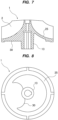
- FIG. 7 is a meridional cross-sectional view of the impeller 1 shown in FIG. 2
- FIG. 8 is a view of the impeller 1 shown in FIG. 2 viewed from its back side. Since the impeller 1 of this embodiment has one swept-back blade 2, the impeller 1 has a balance weight 30 in order to balance the rotation of the impeller 1. This balance weight 30 is provided on the back side of the shroud 25. The balance weight 30 may be integral with the shroud 25.
- the balance weight 30 can prevent vibration of the impeller 1 when the impeller 1 is rotating at high speed and can prevent the impeller 1 from contacting the impeller casing 5.
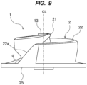
- FIG. 9 is a side view of the impeller 1 shown in FIG. 2 .
- the rear end 22a of the trailing edge 22 is connected diagonally to the shroud 25.
- the rear end 22a of the trailing edge 22 is inclined with respect to the axis CL of the impeller 1.
- a connection angle ⁇ between the rear end 22a of the trailing edge 22 and the shroud 25 is larger than 90 degrees. In other words, the connection angle ⁇ satisfies 90° ⁇ 180°.
- the rear end 22a of the trailing edge 22 corresponds to an outlet of the swept-back blade 2.
- Such an oblique shape of the rear end 22a of the trailing edge 22 can reduce a radial load that the rotating impeller 1 receives from the liquid. As a result, the rotation of the impeller 1 is stabilized.
- connection angle ⁇ between the rear end 22a of the trailing edge 22 and the shroud 25 may be 90 degrees or less than 90 degrees. In other words, the connection angle ⁇ satisfies 0° ⁇ 90°.
- the present invention is applicable to a pump for delivering liquid containing foreign object, such as a string, fiber, or cloth.
Landscapes
- Engineering & Computer Science (AREA)
- Mechanical Engineering (AREA)
- General Engineering & Computer Science (AREA)
- Physics & Mathematics (AREA)
- Geometry (AREA)
- Structures Of Non-Positive Displacement Pumps (AREA)
Abstract
Description
- The present invention relates to a pump for delivering liquid, and particularly to a pump for delivering liquid containing foreign object, such as a string, fiber, or cloth.
- Conventionally, a centrifugal pump has been used to deliver liquid, such as sewage, flowing through a sewer pipe. Such sewage may contain elongated foreign objects, such as strings, fibers, or cloth. Such elongated foreign objects tend to get caught in an impeller of the pump and may impede the rotation of the impeller. Therefore, in order to remove foreign object caught in the impeller, swept-back blades that are less likely to be clogged with foreign object are employed (see, for example, Patent Document 1).
- Patent document 1:
Japanese laid-open patent publication No. 2016-186284 - However, a conventional impeller has two or more swept-back blades. In a small sewage pump, the impeller itself is small in size, and a gap between the blades (hereinafter referred to as passage diameter) is also small. Such a sewage pump cannot have a passage diameter large enough to pass the foreign object. As a result, the impeller may be clogged with the foreign object.
- Therefore, the present invention provides a pump that can prevent an impeller from being clogged with foreign object, such as string, fiber, or cloth.
- In an embodiment, there is provided a pump for delivering liquid containing foreign object, comprising: an impeller; and an impeller casing that accommodates the impeller therein, the impeller including a hub, a single swept-back blade coupled to the hub, and a shroud to which the hub and the swept-back blade are coupled.
- In an embodiment, the swept-back blade has a front edge extending radially outward from the hub, and a trailing edge extending spirally from the front edge in a direction opposite to a rotational direction of the impeller, and a winding angle of the swept-back blade from a center of the front edge to a center of a rear end of the trailing edge is in a range of 320 to 410 degrees.
- In an embodiment, an inner end of the front edge extends in a tangential direction of an outer circumferential surface of the hub.
- In an embodiment, the impeller further includes a balance weight.
- Since the impeller has a single swept-back blade, the passage diameter within the impeller can be large. Therefore, a foreign object contained in a liquid can pass through the impeller without clogging the impeller.
-
- [
FIG. 1] FIG. 1 is a sectional view showing an embodiment of a pump; - [
FIG. 2] FIG. 2 is a front view of an impeller as viewed from a direction indicated by arrow A inFIG. 1 ; - [
FIG. 3] FIG. 3 is a perspective view of the impeller; - [
FIG. 4] FIG. 4 is a front view of a conventional impeller having two swept-back blades; - [
FIG. 5] FIG. 5 is a diagram illustrating a winding angle of a swept-back blade of the impeller shown inFIG. 2 ; - [
FIG. 6] FIG. 6 is a graph showing an example of a relationship between the winding angle of the swept-back blade and impeller efficiency; - [
FIG. 7] FIG. 7 is a meridional cross-sectional view of the impeller shown inFIG. 2 ; - [
FIG. 8] FIG. 8 is a view of the impeller shown inFIG. 2 from its back side; and - [
FIG. 9] FIG. 9 is a side view of the impeller shown inFIG. 2 . - Embodiments of the present invention will be described below with reference to the drawings.
-
FIG. 1 is a sectional view showing an embodiment of a pump. The pump shown inFIG. 1 is, for example, a centrifugal pump used to deliver liquid (e.g., sewage flowing through a sewer pipe) containing foreign object, such as string, fiber, or cloth. - As shown in
FIG. 1 , the pump includes arotation shaft 11, animpeller 1 fixed to therotation shaft 11, and animpeller casing 5 housing theimpeller 1 therein. Therotation shaft 11 is coupled to amotor 12. Theimpeller 1 is rotated together with therotation shaft 11 within theimpeller casing 5 by themotor 12. Amechanical seal 15 is arranged between themotor 12 and theimpeller 1. Thismechanical seal 15 prevents liquid from entering themotor 12. - The
impeller casing 5 has acasing body 6 disposed around theimpeller 1 and acasing liner 8 coupled to thecasing body 6. Theimpeller casing 5 has a suction port 3 and adischarge port 4. More specifically, thecasing liner 8 has the cylindrical suction port 3, and thecasing body 6 has thedischarge port 4. Theimpeller casing 5 has a volute chamber (vortex chamber) 7 formed in thecasing body 6, and theimpeller 1 is arranged in thevolute chamber 7. Thevolute chamber 7 has a shape surrounding theimpeller 1. The suction port 3 and thedischarge port 4 communicate with thevolute chamber 7. - When the
impeller 1 is rotated, liquid is sucked through the suction port 3. The liquid that had flowed through the suction port 3 is discharged into thevolute chamber 7 in a circumferential direction by the rotation of theimpeller 1. Velocity energy is imparted to the liquid by the rotation of theimpeller 1. Furthermore, as the liquid flows through thevolute chamber 7, the velocity energy is converted into pressure, so that the pressure of the liquid is increased. The pressurized liquid is discharged through thedischarge port 4. Ablade 2 of theimpeller 1 faces aninner surface 8a of thecasing liner 8 of theimpeller casing 5 with a slight gap between theblade 2 and theinner surface 8a. This gap is, for example, in a range of 0.3 mm to 0.7 mm. -
FIG. 2 is a front view of theimpeller 1 as viewed from a direction indicated by arrow A inFIG. 1 , andFIG. 3 is a perspective view of theimpeller 1. Theimpeller 1 includes a single swept-back blade 2, acylindrical hub 13, and ashroud 25 to which the swept-back blade 2 and thehub 13 are coupled. Thehub 13 has a through-hole 13a into which an end of therotation shaft 11 shown inFIG. 1 is inserted, so that thehub 13 is fixed to the end of therotation shaft 11 with a fixing device (not shown). Theimpeller 1 is rotated by themotor 12 in a direction indicated by arrow. - The swept-
back blade 2 has afront edge 21 extending radially outward from thehub 13, and atrailing edge 22 extending spirally from thefront edge 21. Thetrailing edge 22 has a spiral shape extending from anouter end 21b of thefront edge 21 in a direction opposite to the rotational direction of theimpeller 1. Arear end 22a of thetrailing edge 22 is located on an outer periphery of theshroud 25 and is coupled to theshroud 25. As shown inFIG. 3 , the entire swept-back blade 2 is inclined with respect to an axis CL of theimpeller 1. - As shown in
FIG. 1 , thefront edge 21 is located in the suction port 3 of theimpeller casing 5 and is exposed in the suction port 3. Thetrailing edge 22 faces the inner surface of the impeller casing 5 (more specifically, theinner surface 8a of the casing liner 8). A minute gap is formed between the trailingedge 22 and theinner surface 8a of thecasing liner 8. - As shown in
FIGS. 2 and3 , theshroud 25 is integral with thehub 13. The swept-back blade 2 is coupled to a front side of theshroud 25, and the swept-back blade 2, thehub 13, and theshroud 25 rotate together. - The
front edge 21 extends radially outward from thehub 13 in an arc shape. More specifically, thefront edge 21 is curved from thehub 13 in a direction opposite to the rotational direction of theimpeller 1. Therefore, theouter end 21b of thefront edge 21 is located more backward than theinner end 21a of thefront edge 21 in the rotational direction of therotation shaft 11. The trailingedge 22 extends spirally from theouter end 21b of thefront edge 21. - The
inner end 21a of thefront edge 21 extends in a tangential direction of an outer circumferential surface of thehub 13 and is smoothly connected to the outer circumferential surface of thehub 13. Actual operations of the pump have confirmed the fact that such a shape of thefront edge 21 causes foreign object in the liquid to move smoothly on thefront edge 21 as theimpeller 1 rotates, thus preventing clogging of theimpeller 1. - In
FIG. 2 , symbol D1 represents a passage diameter through which a foreign object (e.g., string, fiber, or cloth) contained in the liquid can pass. Specifically, if the size of the foreign object is less than or equal to the passage diameter D1, the foreign object is expected to be able to pass through theimpeller 1 together with the liquid without clogging theimpeller 1. -
FIG. 4 is a front view of a conventional impeller having two swept-back blades 100. InFIG. 4 , symbol D2 represents a passage diameter through which a foreign object (e.g., string, fiber, or cloth) contained in liquid can pass. As can be seen from the comparison betweenFIG. 2 andFIG. 4 , theimpeller 1 of this embodiment has the single swept-back blade 2, and therefore the passage diameter D1 in theimpeller 1 is larger than the passage diameter D2 in the conventional impeller of the two-blade type. Therefore, according to this embodiment, foreign object contained in the liquid can pass through theimpeller 1 without clogging theimpeller 1. - As described above, the single swept-
back blade 2 can prevent the foreign object from clogging theimpeller 1, but an impeller efficiency tends to decrease compared to the impeller with multiple swept-back blades. Therefore, in order to improve the impeller efficiency, as shown inFIG. 5 , a winding angle θ of the swept-back blade 2 of this embodiment is in a range of 320 to 410 degrees, more preferably in a range of 330 to 390 degrees. The winding angle θ of the swept-back blade 2 is an angle from a start point to an end point of a camber line D of the swept-back blade 2, in other words, an angle from the center of thefront edge 21 to the center of therear end 22a of the trailingedge 22. More specifically, the winding angle θ of the swept-back blade 2 is defined by an angle between a straight line L1 extending from the center of theimpeller 1 to the center of thefront edge 21 and a straight line L2 extending from the center of theimpeller 1 to the center of therear end 22a of the trailingedge 22. -
FIG. 6 is a graph showing an example of a relationship between the winding angle θ of the swept-back blade 2 and the impeller efficiency. As shown inFIG. 6 , as the winding angle θ of the swept-back blade 2 increases, the impeller efficiency tends to improve. On the other hand, if the winding angle θ of the swept-back blades 2 is too large, the impeller efficiency will actually decrease. In addition, if the winding angle θ of the swept-back blade 2 is too large (particularly if the winding angle of the swept-back blade 2 exceeds 410 degrees), the passage diameter D1 described with reference toFIG. 2 becomes small. From these viewpoints, the winding angle θ of the swept-back blade 2 is in the range of 320 to 410 degrees, more preferably in the range of 330 to 390 degrees. - The
impeller 1 having the single swept-back blade 2 and having the winding angle θ within the above-mentioned range can achieve high impeller efficiency while preventing foreign object from clogging theimpeller 1. -
FIG. 7 is a meridional cross-sectional view of theimpeller 1 shown inFIG. 2 , andFIG. 8 is a view of theimpeller 1 shown inFIG. 2 viewed from its back side. Since theimpeller 1 of this embodiment has one swept-back blade 2, theimpeller 1 has abalance weight 30 in order to balance the rotation of theimpeller 1. Thisbalance weight 30 is provided on the back side of theshroud 25. Thebalance weight 30 may be integral with theshroud 25. - The
balance weight 30 can prevent vibration of theimpeller 1 when theimpeller 1 is rotating at high speed and can prevent theimpeller 1 from contacting theimpeller casing 5. -
FIG. 9 is a side view of theimpeller 1 shown inFIG. 2 . As shown inFIG. 9 , therear end 22a of the trailingedge 22 is connected diagonally to theshroud 25. Specifically, when viewed from a direction perpendicular to the axis CL of theimpeller 1, therear end 22a of the trailingedge 22 is inclined with respect to the axis CL of theimpeller 1. A connection angle α between therear end 22a of the trailingedge 22 and theshroud 25 is larger than 90 degrees. In other words, the connection angle α satisfies 90°<α<180°. - The
rear end 22a of the trailingedge 22 corresponds to an outlet of the swept-back blade 2. Such an oblique shape of therear end 22a of the trailingedge 22 can reduce a radial load that therotating impeller 1 receives from the liquid. As a result, the rotation of theimpeller 1 is stabilized. - In one embodiment, the connection angle α between the
rear end 22a of the trailingedge 22 and theshroud 25 may be 90 degrees or less than 90 degrees. In other words, the connection angle α satisfies 0°<α≤90°. - The previous description of embodiments is provided to enable a person skilled in the art to make and use the present invention. Moreover, various modifications to these embodiments will be readily apparent to those skilled in the art, and the generic principles and specific examples defined herein may be applied to other embodiments. Therefore, the present invention is not intended to be limited to the embodiments described herein but is to be accorded the widest scope as defined by limitation of the claims.
- The present invention is applicable to a pump for delivering liquid containing foreign object, such as a string, fiber, or cloth.
-
- 1
- impeller
- 2
- swept-back blade
- 3
- suction port
- 4
- discharge port
- 5
- impeller casing
- 6
- casing body
- 7
- volute chamber (vortex chamber)
- 8
- casing liner
- 11
- rotation shaft
- 12
- motor
- 13
- hub
- 15
- mechanical seal
- 21
- front edge
- 21a
- inner end of front edge
- 21b
- outer end of front edge
- 22
- trailing edge
- 22a
- rear end of trailing edge
- 25
- shroud
- 30
- balance weight
Claims (4)
- A pump for delivering liquid containing foreign object, comprising:an impeller; andan impeller casing that accommodates the impeller therein,the impeller includinga hub,a single swept-back blade coupled to the hub, anda shroud to which the hub and the swept-back blade are coupled.
- The pump according to claim 1, wherein the swept-back blade has a front edge extending radially outward from the hub, and a trailing edge extending spirally from the front edge in a direction opposite to a rotational direction of the impeller, and a winding angle of the swept-back blade from a center of the front edge to a center of a rear end of the trailing edge is in a range of 320 to 410 degrees.
- The pump according to claim 1, wherein an inner end of the front edge extends in a tangential direction of an outer circumferential surface of the hub.
- The pump according to claim 1, wherein the impeller further includes a balance weight.
Applications Claiming Priority (2)
| Application Number | Priority Date | Filing Date | Title |
|---|---|---|---|
| JP2022072284A JP7803778B2 (en) | 2022-04-26 | 2022-04-26 | pump |
| PCT/JP2022/047062 WO2023210060A1 (en) | 2022-04-26 | 2022-12-21 | Pump |
Publications (2)
| Publication Number | Publication Date |
|---|---|
| EP4517105A1 true EP4517105A1 (en) | 2025-03-05 |
| EP4517105A4 EP4517105A4 (en) | 2026-04-08 |
Family
ID=88518326
Family Applications (1)
| Application Number | Title | Priority Date | Filing Date |
|---|---|---|---|
| EP22940329.0A Pending EP4517105A4 (en) | 2022-04-26 | 2022-12-21 | PUMP |
Country Status (5)
| Country | Link |
|---|---|
| EP (1) | EP4517105A4 (en) |
| JP (1) | JP7803778B2 (en) |
| CN (1) | CN119072581A (en) |
| CA (1) | CA3251903A1 (en) |
| WO (1) | WO2023210060A1 (en) |
Family Cites Families (13)
| Publication number | Priority date | Publication date | Assignee | Title |
|---|---|---|---|---|
| JPS5234042B2 (en) * | 1973-05-09 | 1977-09-01 | ||
| GB2035455B (en) * | 1978-11-17 | 1983-05-11 | Lake G | Single vane rotodynamic impeller |
| DE2924822C2 (en) * | 1979-06-20 | 1985-02-21 | Hans-Ulrich Schleitheim Schneider | Centrifugal screw positive displacement pump |
| DE19717458A1 (en) * | 1997-04-25 | 1998-10-29 | Klein Schanzlin & Becker Ag | Centrifugal pump |
| JP3980708B2 (en) * | 1997-06-18 | 2007-09-26 | 荏原機電株式会社 | Impeller of sewage pump and sewage pump |
| JP5044105B2 (en) | 2005-04-14 | 2012-10-10 | 新明和工業株式会社 | Centrifugal pump impeller and centrifugal pump equipped with the impeller |
| JP5300508B2 (en) | 2009-01-27 | 2013-09-25 | 株式会社クボタ | Pump impeller and pump |
| CN102345630B (en) * | 2010-07-26 | 2015-10-21 | 株式会社久保田 | Impeller of pump and pump |
| JP5916558B2 (en) * | 2012-08-07 | 2016-05-11 | 株式会社鶴見製作所 | Submersible motor pump |
| CN203081851U (en) * | 2013-01-28 | 2013-07-24 | 青岛佳洲泵业有限公司 | Novel balance-adjustable spiral centrifugal impeller |
| EP3276177B1 (en) | 2015-03-27 | 2020-12-02 | Ebara Corporation | Volute pump |
| JP6488167B2 (en) | 2015-03-27 | 2019-03-20 | 株式会社荏原製作所 | Centrifugal pump |
| JP7024822B2 (en) | 2020-06-22 | 2022-02-24 | 株式会社鶴見製作所 | Non-blocking pump |
-
2022
- 2022-04-26 JP JP2022072284A patent/JP7803778B2/en active Active
- 2022-12-21 CA CA3251903A patent/CA3251903A1/en active Pending
- 2022-12-21 EP EP22940329.0A patent/EP4517105A4/en active Pending
- 2022-12-21 CN CN202280094979.6A patent/CN119072581A/en active Pending
- 2022-12-21 WO PCT/JP2022/047062 patent/WO2023210060A1/en not_active Ceased
Also Published As
| Publication number | Publication date |
|---|---|
| CN119072581A (en) | 2024-12-03 |
| EP4517105A4 (en) | 2026-04-08 |
| WO2023210060A1 (en) | 2023-11-02 |
| CA3251903A1 (en) | 2025-02-26 |
| JP2023161750A (en) | 2023-11-08 |
| JP7803778B2 (en) | 2026-01-21 |
Similar Documents
| Publication | Publication Date | Title |
|---|---|---|
| JP4674206B2 (en) | Improved pump impeller | |
| EP3276177B1 (en) | Volute pump | |
| EP3276178B1 (en) | Volute pump | |
| US2419669A (en) | Diffuser for centrifugal compressors | |
| JP2006527804A5 (en) | ||
| EP2453139B1 (en) | Flow vector control for high speed centrifugal pumps | |
| CN102734185A (en) | Counter-rotating axial flow fan | |
| CS203075B2 (en) | Pump,especially of submersible type | |
| JP4605881B2 (en) | Turbo pump inlet structure | |
| CN110073112B (en) | Swirl pump | |
| CN100520080C (en) | Centrifugal impeller and pump apparatus | |
| JP2009221976A (en) | Impeller for centrifugal pump and centrifugal pump | |
| WO2008082428A1 (en) | Reduced tip clearance losses in axial flow fans | |
| JP7803778B2 (en) | pump | |
| CN111201378B (en) | impeller for sewage pump | |
| EP3874169B1 (en) | Eddy pump | |
| WO2010007780A1 (en) | Centrifugal pump impeller and centrifugal pump | |
| JPH08200290A (en) | Centrifugal blower | |
| KR102132233B1 (en) | Impeller for Centrifugal Slurry Pump | |
| US20260132791A1 (en) | Pump | |
| EP3899283A1 (en) | Pump comprising an impeller body provided as an oblique cone | |
| JP5957243B2 (en) | underwater pump | |
| US20260085687A1 (en) | High viscocity pump and rotor for pumping liquids, materials and slurries | |
| JP2000314390A (en) | pump | |
| JP2026061090A (en) | pump |
Legal Events
| Date | Code | Title | Description |
|---|---|---|---|
| STAA | Information on the status of an ep patent application or granted ep patent |
Free format text: STATUS: THE INTERNATIONAL PUBLICATION HAS BEEN MADE |
|
| PUAI | Public reference made under article 153(3) epc to a published international application that has entered the european phase |
Free format text: ORIGINAL CODE: 0009012 |
|
| STAA | Information on the status of an ep patent application or granted ep patent |
Free format text: STATUS: REQUEST FOR EXAMINATION WAS MADE |
|
| 17P | Request for examination filed |
Effective date: 20241015 |
|
| AK | Designated contracting states |
Kind code of ref document: A1 Designated state(s): AL AT BE BG CH CY CZ DE DK EE ES FI FR GB GR HR HU IE IS IT LI LT LU LV MC ME MK MT NL NO PL PT RO RS SE SI SK SM TR |
|
| DAV | Request for validation of the european patent (deleted) | ||
| DAX | Request for extension of the european patent (deleted) | ||
| A4 | Supplementary search report drawn up and despatched |
Effective date: 20260311 |
|
| RIC1 | Information provided on ipc code assigned before grant |
Ipc: F04D 29/24 20060101AFI20260305BHEP Ipc: F04D 7/04 20060101ALI20260305BHEP Ipc: F04D 29/22 20060101ALI20260305BHEP |