EP4517072A2 - Apparatus and process for gas turbine air filtration and fuel vaporization - Google Patents
Apparatus and process for gas turbine air filtration and fuel vaporization Download PDFInfo
- Publication number
- EP4517072A2 EP4517072A2 EP24197113.4A EP24197113A EP4517072A2 EP 4517072 A2 EP4517072 A2 EP 4517072A2 EP 24197113 A EP24197113 A EP 24197113A EP 4517072 A2 EP4517072 A2 EP 4517072A2
- Authority
- EP
- European Patent Office
- Prior art keywords
- air
- filter element
- fuel
- heat exchanger
- gas turbine
- Prior art date
- Legal status (The legal status is an assumption and is not a legal conclusion. Google has not performed a legal analysis and makes no representation as to the accuracy of the status listed.)
- Pending
Links
Images




Classifications
-
- F—MECHANICAL ENGINEERING; LIGHTING; HEATING; WEAPONS; BLASTING
- F02—COMBUSTION ENGINES; HOT-GAS OR COMBUSTION-PRODUCT ENGINE PLANTS
- F02C—GAS-TURBINE PLANTS; AIR INTAKES FOR JET-PROPULSION PLANTS; CONTROLLING FUEL SUPPLY IN AIR-BREATHING JET-PROPULSION PLANTS
- F02C7/00—Features, components parts, details or accessories, not provided for in, or of interest apart form groups F02C1/00 - F02C6/00; Air intakes for jet-propulsion plants
- F02C7/04—Air intakes for gas-turbine plants or jet-propulsion plants
- F02C7/05—Air intakes for gas-turbine plants or jet-propulsion plants having provisions for obviating the penetration of damaging objects or particles
-
- F—MECHANICAL ENGINEERING; LIGHTING; HEATING; WEAPONS; BLASTING
- F02—COMBUSTION ENGINES; HOT-GAS OR COMBUSTION-PRODUCT ENGINE PLANTS
- F02C—GAS-TURBINE PLANTS; AIR INTAKES FOR JET-PROPULSION PLANTS; CONTROLLING FUEL SUPPLY IN AIR-BREATHING JET-PROPULSION PLANTS
- F02C7/00—Features, components parts, details or accessories, not provided for in, or of interest apart form groups F02C1/00 - F02C6/00; Air intakes for jet-propulsion plants
- F02C7/04—Air intakes for gas-turbine plants or jet-propulsion plants
- F02C7/05—Air intakes for gas-turbine plants or jet-propulsion plants having provisions for obviating the penetration of damaging objects or particles
- F02C7/052—Air intakes for gas-turbine plants or jet-propulsion plants having provisions for obviating the penetration of damaging objects or particles with dust-separation devices
-
- B—PERFORMING OPERATIONS; TRANSPORTING
- B01—PHYSICAL OR CHEMICAL PROCESSES OR APPARATUS IN GENERAL
- B01D—SEPARATION
- B01D46/00—Filters or filtering processes specially modified for separating dispersed particles from gases or vapours
- B01D46/0027—Filters or filtering processes specially modified for separating dispersed particles from gases or vapours with additional separating or treating functions
- B01D46/003—Filters or filtering processes specially modified for separating dispersed particles from gases or vapours with additional separating or treating functions including coalescing means for the separation of liquid
- B01D46/0031—Filters or filtering processes specially modified for separating dispersed particles from gases or vapours with additional separating or treating functions including coalescing means for the separation of liquid with collecting, draining means
-
- B—PERFORMING OPERATIONS; TRANSPORTING
- B01—PHYSICAL OR CHEMICAL PROCESSES OR APPARATUS IN GENERAL
- B01D—SEPARATION
- B01D46/00—Filters or filtering processes specially modified for separating dispersed particles from gases or vapours
- B01D46/42—Auxiliary equipment or operation thereof
- B01D46/4263—Means for active heating or cooling
-
- B—PERFORMING OPERATIONS; TRANSPORTING
- B01—PHYSICAL OR CHEMICAL PROCESSES OR APPARATUS IN GENERAL
- B01D—SEPARATION
- B01D46/00—Filters or filtering processes specially modified for separating dispersed particles from gases or vapours
- B01D46/56—Filters or filtering processes specially modified for separating dispersed particles from gases or vapours with multiple filtering elements, characterised by their mutual disposition
- B01D46/62—Filters or filtering processes specially modified for separating dispersed particles from gases or vapours with multiple filtering elements, characterised by their mutual disposition connected in series
-
- F—MECHANICAL ENGINEERING; LIGHTING; HEATING; WEAPONS; BLASTING
- F02—COMBUSTION ENGINES; HOT-GAS OR COMBUSTION-PRODUCT ENGINE PLANTS
- F02C—GAS-TURBINE PLANTS; AIR INTAKES FOR JET-PROPULSION PLANTS; CONTROLLING FUEL SUPPLY IN AIR-BREATHING JET-PROPULSION PLANTS
- F02C3/00—Gas-turbine plants characterised by the use of combustion products as the working fluid
- F02C3/20—Gas-turbine plants characterised by the use of combustion products as the working fluid using a special fuel, oxidant, or dilution fluid to generate the combustion products
- F02C3/22—Gas-turbine plants characterised by the use of combustion products as the working fluid using a special fuel, oxidant, or dilution fluid to generate the combustion products the fuel or oxidant being gaseous at standard temperature and pressure
-
- F—MECHANICAL ENGINEERING; LIGHTING; HEATING; WEAPONS; BLASTING
- F02—COMBUSTION ENGINES; HOT-GAS OR COMBUSTION-PRODUCT ENGINE PLANTS
- F02C—GAS-TURBINE PLANTS; AIR INTAKES FOR JET-PROPULSION PLANTS; CONTROLLING FUEL SUPPLY IN AIR-BREATHING JET-PROPULSION PLANTS
- F02C7/00—Features, components parts, details or accessories, not provided for in, or of interest apart form groups F02C1/00 - F02C6/00; Air intakes for jet-propulsion plants
- F02C7/12—Cooling of plants
- F02C7/14—Cooling of plants of fluids in the plant, e.g. lubricant or fuel
- F02C7/141—Cooling of plants of fluids in the plant, e.g. lubricant or fuel of working fluid
-
- F—MECHANICAL ENGINEERING; LIGHTING; HEATING; WEAPONS; BLASTING
- F02—COMBUSTION ENGINES; HOT-GAS OR COMBUSTION-PRODUCT ENGINE PLANTS
- F02C—GAS-TURBINE PLANTS; AIR INTAKES FOR JET-PROPULSION PLANTS; CONTROLLING FUEL SUPPLY IN AIR-BREATHING JET-PROPULSION PLANTS
- F02C7/00—Features, components parts, details or accessories, not provided for in, or of interest apart form groups F02C1/00 - F02C6/00; Air intakes for jet-propulsion plants
- F02C7/12—Cooling of plants
- F02C7/16—Cooling of plants characterised by cooling medium
-
- F—MECHANICAL ENGINEERING; LIGHTING; HEATING; WEAPONS; BLASTING
- F02—COMBUSTION ENGINES; HOT-GAS OR COMBUSTION-PRODUCT ENGINE PLANTS
- F02C—GAS-TURBINE PLANTS; AIR INTAKES FOR JET-PROPULSION PLANTS; CONTROLLING FUEL SUPPLY IN AIR-BREATHING JET-PROPULSION PLANTS
- F02C7/00—Features, components parts, details or accessories, not provided for in, or of interest apart form groups F02C1/00 - F02C6/00; Air intakes for jet-propulsion plants
- F02C7/22—Fuel supply systems
- F02C7/224—Heating fuel before feeding to the burner
-
- F—MECHANICAL ENGINEERING; LIGHTING; HEATING; WEAPONS; BLASTING
- F23—COMBUSTION APPARATUS; COMBUSTION PROCESSES
- F23R—GENERATING COMBUSTION PRODUCTS OF HIGH PRESSURE OR HIGH VELOCITY, e.g. GAS-TURBINE COMBUSTION CHAMBERS
- F23R3/00—Continuous combustion chambers using liquid or gaseous fuel
- F23R3/02—Continuous combustion chambers using liquid or gaseous fuel characterised by the air-flow or gas-flow configuration
- F23R3/04—Air inlet arrangements
-
- F—MECHANICAL ENGINEERING; LIGHTING; HEATING; WEAPONS; BLASTING
- F23—COMBUSTION APPARATUS; COMBUSTION PROCESSES
- F23R—GENERATING COMBUSTION PRODUCTS OF HIGH PRESSURE OR HIGH VELOCITY, e.g. GAS-TURBINE COMBUSTION CHAMBERS
- F23R3/00—Continuous combustion chambers using liquid or gaseous fuel
- F23R3/28—Continuous combustion chambers using liquid or gaseous fuel characterised by the fuel supply
- F23R3/30—Continuous combustion chambers using liquid or gaseous fuel characterised by the fuel supply comprising fuel prevapourising devices
-
- B—PERFORMING OPERATIONS; TRANSPORTING
- B01—PHYSICAL OR CHEMICAL PROCESSES OR APPARATUS IN GENERAL
- B01D—SEPARATION
- B01D2279/00—Filters adapted for separating dispersed particles from gases or vapours specially modified for specific uses
- B01D2279/60—Filters adapted for separating dispersed particles from gases or vapours specially modified for specific uses for the intake of internal combustion engines or turbines
-
- F—MECHANICAL ENGINEERING; LIGHTING; HEATING; WEAPONS; BLASTING
- F05—INDEXING SCHEMES RELATING TO ENGINES OR PUMPS IN VARIOUS SUBCLASSES OF CLASSES F01-F04
- F05D—INDEXING SCHEME FOR ASPECTS RELATING TO NON-POSITIVE-DISPLACEMENT MACHINES OR ENGINES, GAS-TURBINES OR JET-PROPULSION PLANTS
- F05D2220/00—Application
- F05D2220/30—Application in turbines
- F05D2220/32—Application in turbines in gas turbines
-
- F—MECHANICAL ENGINEERING; LIGHTING; HEATING; WEAPONS; BLASTING
- F05—INDEXING SCHEMES RELATING TO ENGINES OR PUMPS IN VARIOUS SUBCLASSES OF CLASSES F01-F04
- F05D—INDEXING SCHEME FOR ASPECTS RELATING TO NON-POSITIVE-DISPLACEMENT MACHINES OR ENGINES, GAS-TURBINES OR JET-PROPULSION PLANTS
- F05D2260/00—Function
- F05D2260/20—Heat transfer, e.g. cooling
-
- F—MECHANICAL ENGINEERING; LIGHTING; HEATING; WEAPONS; BLASTING
- F05—INDEXING SCHEMES RELATING TO ENGINES OR PUMPS IN VARIOUS SUBCLASSES OF CLASSES F01-F04
- F05D—INDEXING SCHEME FOR ASPECTS RELATING TO NON-POSITIVE-DISPLACEMENT MACHINES OR ENGINES, GAS-TURBINES OR JET-PROPULSION PLANTS
- F05D2260/00—Function
- F05D2260/20—Heat transfer, e.g. cooling
- F05D2260/213—Heat transfer, e.g. cooling by the provision of a heat exchanger within the cooling circuit
-
- F—MECHANICAL ENGINEERING; LIGHTING; HEATING; WEAPONS; BLASTING
- F05—INDEXING SCHEMES RELATING TO ENGINES OR PUMPS IN VARIOUS SUBCLASSES OF CLASSES F01-F04
- F05D—INDEXING SCHEME FOR ASPECTS RELATING TO NON-POSITIVE-DISPLACEMENT MACHINES OR ENGINES, GAS-TURBINES OR JET-PROPULSION PLANTS
- F05D2260/00—Function
- F05D2260/60—Fluid transfer
- F05D2260/607—Preventing clogging or obstruction of flow paths by dirt, dust, or foreign particles
Definitions
- gas turbine arrangements can be configured to utilize a fuel that may result in an inefficient use of energy for vaporizing the fuel for feeding to a gas turbine.
- fuel may be stored as cryogenic liquid (e.g. liquid natural gas or liquid hydrogen) or a cold liquid (e.g. liquid ammonia) and the energy utilized to form the cold liquid can be lost when that fuel is vaporized (e.g. via ambient air vaporizers).
- cryogenic liquid e.g. liquid natural gas or liquid hydrogen
- a cold liquid e.g. liquid ammonia
- the energy utilized to form the cold liquid can be lost when that fuel is vaporized (e.g. via ambient air vaporizers).
- at least some of this liquid fuel can be fed to an air intake filter for vaporization in the filtration device while intake air is being passed through the filtration device for being fed to the gas turbine as an oxidant.
- an apparatus for filtering and cooling air to be fed to a gas turbine while also vaporizing at least a portion of fuel to be fed to the gas turbine can include an inlet filter unit having at least one filter element comprising a first filter element.
- the inlet filter unit can also have a heat exchanger positioned downstream of the first filter element to receive liquid fuel from a fuel storage tank to vaporize the fuel via air passed through the inlet filter unit and to cool the air.
- the inlet filter unit can be positionable to output air after the air is passed through the at least one filter element and the heat exchanger to feed the air to a combustion chamber of a gas turbine.
- the heat exchanger of the inlet filter unit can be configured and positioned to output the fuel so the fuel is at least partially vaporized for feeding to the combustion chamber of the gas turbine.
- the fuel can be ammonia, hydrogen or natural gas or be comprised of ammonia, hydrogen or natural gas (e.g. methane).
- the fuel can be liquid or mostly liquid when fed to the heat exchanger of the inlet filter unit and can be entirely vaporized when output from the heat exchanger.
- the fuel can be partially vaporized when output from the heat exchanger (e.g. be a mixture of heated liquid and gas). Such partially vaporized fuel can be mixed with other vaporized fuel for complete vaporization of the fuel prior to feeding the fuel to the combustion chamber as a gaseous fuel in such embodiments.
- the at least one filter element can include more than the first filter element.
- the at least one filter element can also comprise a second filter element.
- the heat exchanger can be positioned between the first filter element and the second filter element.
- the first filter element can be configured to remove particulates from the air and the second filter element downstream of the first filter element can be configured to remove particulates and/or liquid water from the air.
- the heat exchanger can be positioned downstream of the first filter element and also be positioned downstream of the second filter element.
- the at least one filter element can also include a third filter element that is downstream of the second filter element.
- the first filter element can be configured to remove particulates from the air
- the second filter element can be configured to remove liquid water and/or condensate from the air
- the third filter element can be configured to remove particulates and/or liquid water from the air.
- the third filter element can be positioned downstream of the heat exchanger and the third filter element can be configured to remove liquid water and/or condensate from the air.
- the third filter element can be spaced apart from the heat exchanger or a condensate drainage system downstream of the heat exchanger by a pre-selected condensate falling distance (CFD).
- CFD condensate falling distance
- the at least one filter element can include a second filter element and the heat exchanger can be positioned downstream of the first filter element and can also be positioned upstream of the second filter element.
- the second filter element can be spaced apart from the heat exchanger or a condensate drainage system downstream of the heat exchanger by a pre-selected condensate falling distance (CFD).
- the at least one filter element can also include a third filter element that is downstream of the second filter element and the first filter element can be configured to remove particulates from the air, the second filter element can be configured to remove liquid water and/or condensate from the air, and the third filter element can be configured to remove particulates and/or liquid water from the air.
- the inlet filter unit can have a condensate drainage system positioned downstream of the heat exchanger.
- the condensate drainage system can also (or alternatively) be integrated with the heat exchanger to facilitate drainage of condensate that may form via the cooling of the air that can occur via the fuel vaporization due to the transfer of heat from the air to the liquid fuel to vaporize the fuel.
- the fuel can include ammonia, hydrogen or natural gas (e.g. methane) or be ammonia, hydrogen or natural gas, for example.
- the fuel can include ammonia, hydrogen or natural gas (e.g. methane) or be ammonia, hydrogen or natural gas, for example.
- the fuel can be liquid or mostly liquid when fed to the heat exchanger of the inlet filter unit and can be entirely vaporized when output from the heat exchanger.
- the fuel can be partially vaporized when output from the heat exchanger (e.g. be a mixture of heated liquid and gas). Such partially vaporized fuel can be mixed with other vaporized fuel for complete vaporization of the fuel prior to feeding the fuel to the combustion chamber as a gaseous fuel in such embodiments.
- the process can include other steps.
- the process can also include removing condensate formed as the air passes through the inlet filter unit.
- the process can include feeding another portion of the liquid fuel to a vaporizer to vaporize the fuel and mixing the vaporized fuel output from the vaporizer with the fuel output from the heat exchanger of the inlet filter unit before the fuel is fed to the gas turbine.
- the process can also include filtering the air to remove particulates from the air as the air passes through the inlet filter unit.
- the process can include cycling between cooling of air and also vaporization of fuel via an inlet filter unit and subsequently cessation of feeding fuel to a heat exchanger of an inlet filter unit for cooling of air so that all fuel is vaporized via another vaporization mechanism (e.g. ambient air vaporizer, etc.).
- a heat exchanger of an inlet filter unit for cooling of air so that all fuel is vaporized via another vaporization mechanism (e.g. ambient air vaporizer, etc.).
- another vaporization mechanism e.g. ambient air vaporizer, etc.
- the process can include removing liquid water and/or condensate from the air as it passed through the inlet filter unit.
- the process can utilize or be implemented via an embodiment of our apparatus for filtering and cooling air to be fed to a gas turbine while also vaporizing at least a portion of fuel to be fed to the gas turbine.
- a third filter element can also be positioned downstream of the heat exchanger and the first filter element can be configured to remove particulates from the air, the second filter element can be configured to remove liquid water and/or condensate from the air, and the third filter element can be configured to remove particulates and/or liquid water from the air.
- a turbine apparatus in a tenth aspect, can include an inlet filter unit having at least one filter element comprising a first filter element and a heat exchanger positioned downstream of the first filter element to receive liquid fuel to vaporize the fuel via air passed through the inlet filter unit to cool the air.
- the inlet filter unit can be positionable to output air after the air is passed through the filter elements to feed the air to a combustion chamber of a gas turbine.
- the heat exchanger can be configured and positioned to output the fuel so the fuel is vaporized for feeding to the combustion chamber of the gas turbine.
- Aspect 3 The apparatus of Aspect 2, wherein the at least one filter element includes a third filter element that is downstream of the second filter element.
- Aspect 4 The apparatus of Aspect 3, wherein the first filter element is configured to remove particulates from the air, the second filter element is configured to remove liquid water and/or condensate from the air, and the third filter element is configured to remove particulates and/or liquid water from the air.
- Aspect 5 The apparatus of Aspect 1, wherein the first filter element is configured to remove particulates from the air and the at least one filter element also includes a second filter element downstream of the first filter element that is configured to remove particulates and/or liquid water from the air.
- Aspect 7 The apparatus of Aspect 6, wherein the at least one filter element includes a third filter element that is downstream of the heat exchanger, the third filter element configured to remove liquid water and/or condensate from the air.
- Aspect 8 The apparatus of Aspect 7, wherein the third filter element is spaced apart from the heat exchanger or a condensate drainage system downstream of the heat exchanger by a pre-selected condensate falling distance (CFD).
- CFD condensate falling distance
- Aspect 10 The apparatus of Aspect 1, wherein the at least one filter element also includes a second filter element and the heat exchanger is positioned downstream of the first filter element and is also positioned upstream of the second filter element, the second filter element being spaced apart from the heat exchanger or a condensate drainage system downstream of the heat exchanger by a pre-selected condensate falling distance (CFD).
- CFD condensate falling distance
- Aspect 11 The apparatus of Aspect 10, wherein the at least one filter element includes a third filter element that is downstream of the second filter element; and wherein the first filter element is configured to remove particulates from the air, the second filter element is configured to remove liquid water and/or condensate from the air, and the third filter element is configured to remove particulates and/or liquid water from the air.
- Aspect 14 The process of Aspect 12, comprising:
- Aspect 17 The process of Aspect 15, wherein the inlet filter unit has a plurality of filter elements comprising a first filter element and a second filter element, at least one of the filter elements being upstream of the heat exchanger.
- Aspect 18 The process of Aspect 17, wherein the first filter element is configured to remove particulates from the air and the second filter element is configured to remove liquid water and/or condensate from the air or the second element is configured to remove particulates and/or liquid water from the air.
- Aspect 19 The process of Aspect 17, wherein the filter elements also include a third filter element downstream of the heat exchanger; and wherein the first filter element is configured to remove particulates from the air, the second filter element is configured to remove liquid water and/or condensate from the air, and the third filter element is configured to remove particulates and/or liquid water from the air.
- a turbine apparatus comprising:
- Exemplary embodiments of our process for gas turbine operations, a gas turbine apparatus, a system for gas turbine operation, a process for filtering and cooling air to be fed to a gas turbine while also vaporizing at least a portion of fuel to be fed to the gas turbine, an apparatus for filtering and cooling air to be fed to a gas turbine while also vaporizing at least a portion of fuel to be fed to the gas turbine, and methods of making and using the same are shown in the drawings included herewith. It should be understood that like reference characters used in the drawings may identify like components.
- a gas turbine apparatus 1 can include a source of fuel that can be stored in a fuel storage tank 3.
- the fuel storage tank 3 can include at least one vessel configured to store the fuel as a cryogenic liquid (e.g. liquid natural gas) or as a liquid (e.g. liquid ammonia).
- the fluid of the fuel storage tank 3 can comprise liquid and can be outputtable from the fuel storage tank via a feed pump 5 connected to the fuel storage tank 3 via a feed pump conduit 2 connected between the feed pump 5 and the fuel storage tank 3.
- the feed pump 5 can be positioned to help drive a flow of the fuel toward the gas turbine 11.
- the feed pump 5 can increase the pressure of the fuel within the fuel storage tank 3 to a pre-selected operational pressure for feeding the fuel to the gas turbine 11.
- a pre-selected operational pressure can be a pressure within a range of 40 atm and 80 atm, between 20 atm and 60 atm, between 20 atm and 80 atm, or other suitable pressure range.
- the feed pump 5 can be connected to a vaporizer feed conduit 4a that is connected between the feed pump 5 and the vaporizer 7. At least a portion of the fuel can be fed to the vaporizer via the vaporizer feed conduit 4a for being vaporized so that the fuel can be output from the vaporizer 7 via a vaporizer output conduit 6 connected to the vaporizer so that the fuel can be output from the vaporizer 7 as a gas for being fed to a combustion chamber of the gas turbine as a gaseous fuel.
- the heating medium for the vaporizer 7 for heating the fuel to vaporize it can be ambient air, an industrial process gas, or other suitable heating medium.
- a combustion chamber feed conduit 6b (shown in broken line in Figure 1 ) can be connected between a vaporizer output conduit 6 and the gas turbine 11 for feeding the vaporized fuel output from the vaporizer to the gas turbine.
- the feed pump 5 can also be connected to an inlet filter unit feed conduit 4b that is connected between an inlet filter unit 9 and the feed pump 5. A portion of the fuel output from the feed pump 5 can be passed to the inlet filter unit 9 via this conduit to be vaporized via air being passed through the inlet filter unit 9.
- a valve V can be positioned to adjust how much of the fuel output from the feed pump 5 is passed to the inlet filter unit 9.
- the valve V can be connected to the inlet filter unit feed conduit 4b at a position between the inlet filter unit 9 and the feed pump 5.
- the valve V can be adjustable from a closed position in which no fuel is fed to the inlet filter unit 9 and an open position in which a portion of the fuel is passed to the inlet filter unit 9 for being vaporized therein.
- a controller (not shown) having a processor connected to a non-transitory memory and at least one transceiver can be communicatively connected to the valve to actuate adjustment of the valve to different positions between its closed and open position.
- valve V and conduits connected to the feed pump 5 can be arranged so that when the valve V is in a fully opened position, all the fuel is passed to the inlet filter unit 9 for being vaporized therein and the vaporizer 7 is not utilized for vaporizing the fuel in such an operational state.
- the vaporizer feed conduit 4a can also include a valve that can be closed to help facilitate such a flow of the fuel to the inlet filter unit 9.
- the gas turbine 11 can receive the filter air flow FA and the feed of gaseous fuel output from the vaporizer 7 and/or the inlet filter unit 9 for combusting the fuel in the combustion chamber of the gas turbine 11.
- Combustion of the fuel can drive rotation of at least one shaft as exhaust gas that includes the combustion products from the combusted fuel is output from the gas turbine 11 as a stream of exhaust (Exhaust).
- the exhaust can be vented to atmosphere directly or after being passed through an exhaust treatment system.
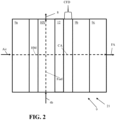
- Figure 2 illustrates a first exemplary embodiment of an inlet filter unit 9 that is configured to filter air via multiple filter elements and also cool the air via a heat transfer with fuel passed through a heat exchanger HX of the inlet filter unit 9 positioned between filter elements of the inlet filter unit 9.
- the air can be passed through a first filter element 9a positioned upstream of the heat exchanger HX.
- the first filter element 9a can include one or more mesh elements or other type of particulate removal members for removal of particulates from the air.
- Some embodiments of the first filter element 9a can also be configured to remove rain from the air as well. The removal of particulates and/or rain from the air can help protect the heat exchanger HX by preventing fouling of heat exchanger elements.
- the inlet filter unit 9 can also include a condensate drainage system 12 positioned adjacent to the heat exchanger HX and downstream of the heat exchanger HX to help remove condensate that can form when the air contacts one or more cold coils or heat transfer conduits of the heat exchanger HX through which the liquid fuel can pass.
- the formed condensate that is drained can include liquid water that may condense from the air as it contacts the one or more heat transfer conduits through which the fuel passes, for example.
- the inlet filter unit 9 can be arranged and configured so that there is a pre-selected condensate falling distance CFD of space between the heat exchanger HX (or the condensate drainage system 12) and the second filter element 9b downstream of the heat exchanger.
- the condensate falling distance CFD can be selected to facilitate the fall of condensate from within the cooled air flow CA so that the condensate can fall and/or agglomerate to help facilitate filtration via the second filter element 9b and/or third filter element 9c downstream of the heat exchanger HX.
- the second filter element 9b that is upstream of the heat exchanger HX and downstream of the first filter element 9a can be configured as a hydrophobic filter configured to remove fine particulates from the air while also helping to remove liquid water from the air as well.
- the second filter element 9b can be positioned to help maintain the filtered air output from the inlet filter unit 9 so it has a liquid water content that is at or below a pre-selected liquid water content threshold and also has a particulate content that is at or below a pre-selected particulate content for the filtered air flow FA.
- the heat exchanger HX can be positioned downstream of the second filter element 9b so that the air passed through the second filter element 9b can function as a heating medium HM and pass along the one or more coils or other heat transfer conduits of the heat exchanger through which the fuel passes to heat the fuel (and thereby cool the air) to form the cooled air flow CA.
- a condensate drainage system 12 can be positioned downstream of the heat exchanger HX to help remove any condensate that may form as the air contacts the cold heat transfer conduits of the heat exchanger HX through which the fuel passes.
- the cooled air flow CA can be output from the inlet filter unit 9 as the filtered air flow FA after passing through the heat exchanger HX or after passing the condensate drainage system 12 without passing through any further downstream filter elements.
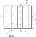
- Figure 5 illustrates yet another embodiment of the inlet filter unit 9 in which the heat exchanger HX of the inlet filter unit 9 can be downstream of both the first filter element 9a and the second filter element 9b and also be upstream of a third filter element 9c.
- the first filter element 9a can be positioned upstream of the heat exchanger HX and upstream of the second filter element 9b.
- the first filter element 9a can include one or more mesh elements or other type of particulate removal members for removal of particulates from the air.
- the second filter element 9b that is upstream of the heat exchanger HX and downstream of the first filter element 9a can be configured as a hydrophobic filter configured to remove fine particulates from the air while also helping to remove liquid water from the air as well.
- the second filter element 9b can be positioned to help maintain the filtered air output from the inlet filter unit 9 so it has a liquid water content that is at or below a pre-selected liquid water content threshold (e.g. no liquid water and no liquid condensate, etc.) and also has a particulate content that is at or below a pre-selected particulate content for the filtered air flow FA.
- a pre-selected liquid water content threshold e.g. no liquid water and no liquid condensate, etc.
- Prevention of liquid water from passing through all the filter elements of the inlet filter unit 9 can be beneficial in some embodiments by helping to prevent salt that may be within the air from egressing through the filter elements and slipping past the inlet filter unit 9, which can contribute to corrosion or other degradation of downstream gas turbine equipment.
- the heat exchanger HX can be positioned downstream of the second filter element 9b and also be positioned upstream of a third filter element 9c so that the air passed through the second filter element 9b can function as a heating medium HM and pass along the one or more coils or other heat transfer conduits of the heat exchanger through which the fuel passes to heat the fuel (and thereby cool the air) to form the cooled air flow CA.
- a condensate drainage system 12 can be positioned downstream of the heat exchanger HX to help remove any condensate that may form as the air contacts the cold heat transfer conduits of the heat exchanger HX through which the fuel passes.
- the third filter element 9c can be positioned downstream of the heat exchanger.
- the third filter element 9c can also be spaced apart from the heat exchanger HX or condensate drainage system 12 by a pre-selected condensate falling distance CFD of space so that condensate from within the cooled air flow CA can fall and/or agglomerate to help facilitate filtration via the third filter element 9c downstream of the heat exchanger HX.
- the pre-selected condensate falling distance CFD is selected so that most of the condensate can fall out of the air prior to reaching the downstream third filter element 9c, which can also help reduce the pressure drop that can occur from the air passing through the filter element.
- air can be fed into an inlet filter unit 9 (e.g. a filter house or other type of inlet filter unit 9) for filtration.
- the filtration of the air can remove particulates or can remove particulates and liquid water from the air.
- Such filtration can be provided by a first filter element 9a, second filter element 9b, and/or a third filter element 9c as discussed above, for example.
- a portion of liquid fuel can be fed into the inlet filter unit 9 (e.g. filter house or other type of inlet filter unit 9).
- the fuel can be fed into the inlet filter unit for vaporization of the fuel via a heat exchange with the air passed through the inlet filter unit 9 as discussed above, for example.
- the passing of the fuel into the heat exchanger of the inlet filter unit 9 can occur while the air is being filtered in the inlet filter unit 9.
- a third step S3 at least partially vaporized fuel can be output from the inlet filter unit's heat exchanger HX and filter air (e.g. filtered air flow FA) that is cooled can be output from the inlet filter unit 9 for feeding the vaporized fuel and the filtered, cooled air to the gas turbine 11.
- filter air e.g. filtered air flow FA
- Examples of the outputting of the filtered, cooled air and the vaporized fuel from the inlet filter unit 9 to the gas turbine 11 are discussed above.
- step S4 at least some condensate that can form from the air cooling in the inlet filter unit 9 can be removed.
- the removal of the condensate can be provided via at least one filter element and/or a condensate drainage system 12 as discussed above, for example.
- the removal of the condensate can remove at least some of the condensate from the air so that the air output from the inlet filter unit no longer has such condensate or has a relatively low amount of condensate entrained therein.
- Embodiments of the process and apparatus can utilize a distributed control system (DCS) or automated process control system to monitor and/or control operations.
- a controller of such a system can be utilized to control how much of the fuel is fed to the gas turbine 11 and what proportion of the fuel is fed to the vaporizer 7 for vaporization and how much of the fuel is fed to the inlet filter unit 9 for vaporization of the fuel and cooling of the air.
- Such control operations can be based on sensor data obtained from different sensors of the apparatus and/or operator input that can be provided to controller of the control system.
- a temperature sensor can be positioned adjacent a discharge outlet of the inlet filter unit 9 to measure the filtered air temperature of the filter air flow FA output from the inlet filter unit 9.
- Such temperature data can be provided to a controller for use in modulating the flow of liquid fuel fed to the inlet filter unit 9 (e.g. if the temperature of the filtered air flow is over a pre-selected high temperature threshold, more fuel can be fed to the inlet filter unit's heat exchanger and if the temperature is below a pre-selected low temperature threshold, less fuel can be fed to the inlet filter unit's heat exchanger).
- Embodiments of our process and apparatus can be configured so that heat that may be required to vaporize a fuel for being fed to a gas turbine can utilize air to be fed to the gas turbine as an oxidant flow to provide a more energy efficient fuel vaporization scheme that can help reduce costs and environmental impacts associated with the user of other options for heating the fuel (e.g. electric heat vaporizers, etc.).
- the cooling of the oxidant to be fed to the combustion chamber of the gas turbine can provide a benefit as it can help increase the air mass flow rate fed to the combustion chamber of the gas turbine 11, which can improve gas turbine performance. This can be particularly advantageous in in warmer climates that have higher temperature ambient air.
- the heat exchange process used for vaporization can be more efficient and require less maintenance.
- the removal of particulates upstream of the heat exchanger HX within the inlet filter unit 9 can remove particulates from the air, which can avoid fouling or other degradation issues.
- the use of the inlet air within the inlet filter unit 9 to vaporize the fuel can help reduce the energy required to vaporize the fuel while simultaneously cooling the inlet air to be fed to the gas turbine as an oxidant to increase turbine performance.
- Embodiments can also provide improved operational flexibility for the turbine apparatus 1. For example, in some operational situations, it may not be desired to utilize the inlet filter unit for vaporization of fuel. This may occur, for example, during a turbine startup operation or due to maintenance work that may be needed for the heat exchanger HX of the inlet filter unit 9. In such situations, the valve V of the inlet filter unit feed conduit 4b can be closed and all the fuel can be fed to the vaporizer 7 for providing the vaporized fuel to the gas turbine 11.
- valve V of the inlet filter unit feed conduit 4b can subsequently be adjusted to an open position when it is advantageous to have at least some of the fuel vaporized via the air passed through the inlet filter unit 9.
- the use of the inlet filter unit 9 for cooling of air and vaporization of at least some of the fuel to be fed to the gas turbine 11 can be adapted to meet ambient operational conditions and the operational demand for the gas turbine 11 to provide improved operational flexibility that can reduce turbine downtime and provide improved turbine performance.
- the turbine apparatus 1 can be configured for operation at a pre-selected operational pressure.
- This pre-selected operational pressure can be a suitable pressure selected to account for the size of the turbine apparatus, fuel to be combusted therein, and other design criteria.
- Operational temperatures within a pre-selected temperature range can also be selected based on the types of fuel to be combusted, flow of air to be fed to the gas turbine 11, size of the gas turbine 11, and other design criteria.
- Embodiments of our process, apparatus, and system can be adapted for different turbine apparatus design criteria.
- other embodiments can utilize different types of conduit arrangements, fuel storage tanks, types of liquid fuel (e.g. liquid ammonia, liquid natural gas, etc.).
- some inlet filter units 9 may only include a single filter element (e.g. a jet pulse filter, etc.) while others may include more than 2 filter elements, more than 3 filter elements, or more than 4 filter elements.
- some inlet filter units 9 can include a vane separator or other type of moisture removal device adjacent the inlet of the inlet filter unit 9 to help remove moisture from the air.
- valves, piping, and other conduit elements e.g., conduit connection mechanisms, tubing, seals, valves, etc.
- conduit connection mechanisms e.g., tubing, seals, valves, etc.
- flow rate, pressure, and temperature of the fluid passed through the various apparatus or system elements can vary to account for different design configurations and other design criteria.
- Embodiments of the gas turbine apparatus 1, process for operation of a gas turbine, apparatus for filtering and cooling air to be fed to a gas turbine while also vaporizing at least a portion of fuel to be fed to the gas turbine, and process for filtering and cooling air to be fed to a gas turbine while also vaporizing at least a portion of fuel to be fed to the gas turbine can each be configured to include process control elements positioned and configured to monitor and control operations (e.g., temperature and pressure sensors, flow sensors, an automated process control system having at least one work station that includes a processor, non-transitory memory and at least one transceiver for communications with the sensor elements, valves, and controllers for providing a user interface for an automated process control system that may be run at the work station and/or another computer device of the plant, etc.).
- DCS distributed control system
Landscapes
- Engineering & Computer Science (AREA)
- Chemical & Material Sciences (AREA)
- Combustion & Propulsion (AREA)
- Mechanical Engineering (AREA)
- General Engineering & Computer Science (AREA)
- Chemical Kinetics & Catalysis (AREA)
- Filtering Of Dispersed Particles In Gases (AREA)
- Processes For Solid Components From Exhaust (AREA)
- Engine Equipment That Uses Special Cycles (AREA)
Abstract
Description
- The present innovation relates to gas turbines, operations of gas turbines, and processes for filtering and cooling air to be fed to a gas turbine while also vaporizing at least a portion of fuel to be fed to the gas turbine.
- Gas turbines can combust a fuel for generation of power or work. Examples of different types of gas turbines and arrangements for gas turbines can be appreciated from
U.S. Patent Nos. 11,592,178 6,752,620 ,U.S. Patent Application Publication Nos. 2022/0268444 and2013/0127163 , and Chinese Patent Publication No.CN114876641A . - We determined that gas turbine arrangements can be configured to utilize a fuel that may result in an inefficient use of energy for vaporizing the fuel for feeding to a gas turbine. For example, fuel may be stored as cryogenic liquid (e.g. liquid natural gas or liquid hydrogen) or a cold liquid (e.g. liquid ammonia) and the energy utilized to form the cold liquid can be lost when that fuel is vaporized (e.g. via ambient air vaporizers). We determined that at least some of this liquid fuel can be fed to an air intake filter for vaporization in the filtration device while intake air is being passed through the filtration device for being fed to the gas turbine as an oxidant. We determined that this type of approach can permit the air to be cooled as it is filtered to provide improved performance as an oxidant in the gas turbine while also providing a heating medium for vaporization of at least some of the fuel for feeding that fuel to the gas turbine for being combusted therein. We also determined that such an approach can help prevent heat exchanger fouling by facilitating the heat exchange between the air and the fuel after the air has passed through at least one filter mechanism to remove particulates from the air.
- We determined that embodiments of our apparatus and process can facilitate improved gas turbine operation to permit a more efficient, cost effective approach for vaporization of fuel and pre-treating of air for feeding to the gas turbine as an oxidant. Embodiments can also provide enhanced operational flexibility such that fuel vaporization via the air intake filter may only occur when needed to help cool the air to a desired feed temperature to provide more flexibility to account for changes in ambient conditions and gas turbine operational demands.
- We have determined that embodiments can also permit more efficient use of the cold of a cryogenic liquid fuel (e.g. liquid natural gas or liquid hydrogen) or cold of a liquified fuel that may be at a relatively cold temperature (e.g. liquid ammonia, which may be stored at a temperature of between -6°C to -35°C or -30°C and -33°C) that is stored as a source of fuel for the gas turbine so that less of the energy utilized to cool the fuel to a liquid is lost when the fuel is fed to a gas turbine for being combusted therein. The improved energy efficiency can permit a more environmentally friendly operation of gas turbines to be provided that also provides reduced operational costs.
- In some embodiments, the fuel that can be utilized can be ammonia and/or natural gas. Such fuels can be stored as a cryogenic liquid or a cold liquid and subsequently vaporized for being fed to the gas turbine for combustion therein. In situations where the fuel is ammonia, the ammonia can be provided via a green ammonia manufacturing process (e.g. use of renewable power to form the ammonia from electrolysis of water to form hydrogen and air separation to provide the nitrogen for forming the ammonia). Such embodiments can provide gas turbine operations that can occur more efficiently while also providing a relatively minimal environmental impact, or a significantly reduced environmental impact.
- In a first aspect, an apparatus for filtering and cooling air to be fed to a gas turbine while also vaporizing at least a portion of fuel to be fed to the gas turbine is provided. The apparatus can include an inlet filter unit having at least one filter element comprising a first filter element. The inlet filter unit can also have a heat exchanger positioned downstream of the first filter element to receive liquid fuel from a fuel storage tank to vaporize the fuel via air passed through the inlet filter unit and to cool the air. The inlet filter unit can be positionable to output air after the air is passed through the at least one filter element and the heat exchanger to feed the air to a combustion chamber of a gas turbine. The heat exchanger of the inlet filter unit can be configured and positioned to output the fuel so the fuel is at least partially vaporized for feeding to the combustion chamber of the gas turbine.
- In some embodiments, the fuel can be ammonia, hydrogen or natural gas or be comprised of ammonia, hydrogen or natural gas (e.g. methane). The fuel can be liquid or mostly liquid when fed to the heat exchanger of the inlet filter unit and can be entirely vaporized when output from the heat exchanger. In other embodiments, the fuel can be partially vaporized when output from the heat exchanger (e.g. be a mixture of heated liquid and gas). Such partially vaporized fuel can be mixed with other vaporized fuel for complete vaporization of the fuel prior to feeding the fuel to the combustion chamber as a gaseous fuel in such embodiments.
- In a second aspect, the at least one filter element can include more than the first filter element. For example, the at least one filter element can also comprise a second filter element. The heat exchanger can be positioned between the first filter element and the second filter element.
- In other embodiments, the first filter element can be configured to remove particulates from the air and the second filter element downstream of the first filter element can be configured to remove particulates and/or liquid water from the air. The heat exchanger can be positioned downstream of the first filter element and also be positioned downstream of the second filter element.
- As another example, the at least one filter element can also include a third filter element that is downstream of the second filter element. The first filter element can be configured to remove particulates from the air, the second filter element can be configured to remove liquid water and/or condensate from the air, and the third filter element can be configured to remove particulates and/or liquid water from the air.
- In some embodiments, the third filter element can be positioned downstream of the heat exchanger and the third filter element can be configured to remove liquid water and/or condensate from the air. For example, the third filter element can be spaced apart from the heat exchanger or a condensate drainage system downstream of the heat exchanger by a pre-selected condensate falling distance (CFD).
- As yet another example, the at least one filter element can include a second filter element and the heat exchanger can be positioned downstream of the first filter element and can also be positioned upstream of the second filter element. The second filter element can be spaced apart from the heat exchanger or a condensate drainage system downstream of the heat exchanger by a pre-selected condensate falling distance (CFD). In some configurations, the at least one filter element can also include a third filter element that is downstream of the second filter element and the first filter element can be configured to remove particulates from the air, the second filter element can be configured to remove liquid water and/or condensate from the air, and the third filter element can be configured to remove particulates and/or liquid water from the air.
- In yet other embodiments, the at least one filter unit can include more than three filter elements. Each additional filter element can be positioned to help remove particulates and/or liquid from the air that is cooled via the vaporization of fuel that can occur via the heat exchanger.
- In a third aspect, the inlet filter unit can have a condensate drainage system positioned downstream of the heat exchanger. The condensate drainage system can also (or alternatively) be integrated with the heat exchanger to facilitate drainage of condensate that may form via the cooling of the air that can occur via the fuel vaporization due to the transfer of heat from the air to the liquid fuel to vaporize the fuel.
- In a fourth aspect, the apparatus of the first aspect can include one or more features of the second aspect and/or the third aspect. It should therefore be appreciated that different embodiments can include other features or combinations of features. Examples of different features that can be included in an exemplary embodiment can be appreciated from the discussion of exemplary embodiments discussed herein.
- In a fifth aspect, a process for filtering and cooling air to be fed to a gas turbine while also vaporizing at least a portion of fuel to be fed to the gas turbine is provided. The process can include feeding air into an inlet filter unit for filtration of the air, feeding a portion of liquid fuel into a heat exchanger of the inlet filter unit for vaporization of the portion of the fuel via heat exchange with the air passing through the inlet filter unit, outputting at least partially vaporized fuel from the heat exchanger of the inlet filter unit to a gas turbine and outputting filtered air from the inlet filter unit that is cooled via the heat exchange with the fuel to the gas turbine.
- Embodiments of the process can be utilized in conjunction with different types of fuels. In some embodiments, the fuel can include ammonia, hydrogen or natural gas (e.g. methane) or be ammonia, hydrogen or natural gas, for example.
- In some embodiments of the process, the fuel can be liquid or mostly liquid when fed to the heat exchanger of the inlet filter unit and can be entirely vaporized when output from the heat exchanger. In other embodiments, the fuel can be partially vaporized when output from the heat exchanger (e.g. be a mixture of heated liquid and gas). Such partially vaporized fuel can be mixed with other vaporized fuel for complete vaporization of the fuel prior to feeding the fuel to the combustion chamber as a gaseous fuel in such embodiments.
- In a sixth aspect, the process can include other steps. For example, the process can also include removing condensate formed as the air passes through the inlet filter unit. As another example, the process can include feeding another portion of the liquid fuel to a vaporizer to vaporize the fuel and mixing the vaporized fuel output from the vaporizer with the fuel output from the heat exchanger of the inlet filter unit before the fuel is fed to the gas turbine. As yet another example, the process can also include filtering the air to remove particulates from the air as the air passes through the inlet filter unit.
- As yet another example, the process can include cycling between cooling of air and also vaporization of fuel via an inlet filter unit and subsequently cessation of feeding fuel to a heat exchanger of an inlet filter unit for cooling of air so that all fuel is vaporized via another vaporization mechanism (e.g. ambient air vaporizer, etc.). Such cycling can be configured to occur based on gas turbine operational data and/or ambient air condition data, for example.
- In a seventh aspect, the process can include removing liquid water and/or condensate from the air as it passed through the inlet filter unit.
- In an eighth aspect, the process can utilize or be implemented via an embodiment of our apparatus for filtering and cooling air to be fed to a gas turbine while also vaporizing at least a portion of fuel to be fed to the gas turbine.
- In such embodiments, the inlet filter unit can include a plurality of filter elements comprising a first filter element and a second filter element wherein at least one of the filter elements is upstream of the heat exchanger. As discussed above, the filter elements can also include additional filter elements (e.g. a third filter element, a fourth filter element, etc.). In some embodiments, the first filter element can be configured to remove particulates from the air and the second filter element can be configured to remove liquid water and/or condensate from the air or the second element can be configured to remove particulates and/or liquid water from the air. In some configurations, a third filter element can also be positioned downstream of the heat exchanger and the first filter element can be configured to remove particulates from the air, the second filter element can be configured to remove liquid water and/or condensate from the air, and the third filter element can be configured to remove particulates and/or liquid water from the air.
- In a ninth aspect, the process of the fifth aspect can include one or more features of the sixth aspect, seventh aspect, and/or the eighth aspect. It should therefore be appreciated that different embodiments can include other features or combinations of features. Examples of different features that can be included in an exemplary embodiment can be appreciated from the discussion of exemplary embodiments discussed herein.
- In a tenth aspect, a turbine apparatus is provided. The turbine apparatus can include an inlet filter unit having at least one filter element comprising a first filter element and a heat exchanger positioned downstream of the first filter element to receive liquid fuel to vaporize the fuel via air passed through the inlet filter unit to cool the air. The inlet filter unit can be positionable to output air after the air is passed through the filter elements to feed the air to a combustion chamber of a gas turbine. The heat exchanger can be configured and positioned to output the fuel so the fuel is vaporized for feeding to the combustion chamber of the gas turbine.
- Embodiment of the gas turbine apparatus can be configured to implement an embodiment of the process for filtering and cooling air to be fed to a gas turbine while also vaporizing at least a portion of fuel to be fed to the gas turbine is provided. Embodiments of the turbine apparatus can also be configured to include an embodiment of the inlet filter unit of an embodiment of the apparatus for filtering and cooling air to be fed to a gas turbine while also vaporizing at least a portion of fuel to be fed to the gas turbine is provided.
- It should be appreciated that embodiments of the process and apparatus can utilize various conduit arrangements and process control elements. The embodiments may utilize sensors (e.g., pressure sensors, temperature sensors, flow rate sensors, concentration sensors, etc.), controllers, valves, piping, and other process control elements. Some embodiments can utilize an automated process control system and/or a distributed control system (DCS), for example. Various different conduit arrangements and process control systems can be utilized to meet a particular set of design criteria.
- Several aspects of apparatus and processes are outlined below.
- Aspect 1: An apparatus for filtering and cooling air to be fed to a gas turbine while also vaporizing at least a portion of fuel to be fed to the gas turbine, the apparatus comprising:
- an inlet filter unit having at least one filter element comprising a first filter element, the inlet filter unit also having a heat exchanger positioned downstream of the first filter element to receive liquid fuel from a fuel storage tank to vaporize the fuel via air passed through the inlet filter unit and to cool the air;
- the inlet filter unit being positionable to output air after the air is passed through the at least one filter element and the heat exchanger to feed the air to a combustion chamber of a gas turbine; and
- the heat exchanger of the inlet filter unit being configured and positioned to output the fuel so the fuel is at least partially vaporized for feeding to the combustion chamber of the gas turbine.
- Aspect 2: The apparatus of
Aspect 1, wherein the at least one filter element also comprises a second filter element and the heat exchanger is positioned between the first filter element and the second filter element. - Aspect 3: The apparatus of
Aspect 2, wherein the at least one filter element includes a third filter element that is downstream of the second filter element. - Aspect 4: The apparatus of
Aspect 3, wherein the first filter element is configured to remove particulates from the air, the second filter element is configured to remove liquid water and/or condensate from the air, and the third filter element is configured to remove particulates and/or liquid water from the air. - Aspect 5: The apparatus of
Aspect 1, wherein the first filter element is configured to remove particulates from the air and the at least one filter element also includes a second filter element downstream of the first filter element that is configured to remove particulates and/or liquid water from the air. - Aspect 6: The apparatus of
Aspect 5, wherein the heat exchanger is positioned downstream of the first filter element and is also positioned downstream of the second filter element. - Aspect 7: The apparatus of
Aspect 6, wherein the at least one filter element includes a third filter element that is downstream of the heat exchanger, the third filter element configured to remove liquid water and/or condensate from the air. - Aspect 8: The apparatus of Aspect 7, wherein the third filter element is spaced apart from the heat exchanger or a condensate drainage system downstream of the heat exchanger by a pre-selected condensate falling distance (CFD).
- Aspect 9: The apparatus of
Aspect 1, wherein the inlet filter unit has a condensate drainage system positioned downstream of the heat exchanger. - Aspect 10: The apparatus of
Aspect 1, wherein the at least one filter element also includes a second filter element and the heat exchanger is positioned downstream of the first filter element and is also positioned upstream of the second filter element, the second filter element being spaced apart from the heat exchanger or a condensate drainage system downstream of the heat exchanger by a pre-selected condensate falling distance (CFD). - Aspect 11: The apparatus of
Aspect 10, wherein the at least one filter element includes a third filter element that is downstream of the second filter element; and
wherein the first filter element is configured to remove particulates from the air, the second filter element is configured to remove liquid water and/or condensate from the air, and the third filter element is configured to remove particulates and/or liquid water from the air. - Aspect 12: A process for filtering and cooling air to be fed to a gas turbine while also vaporizing at least a portion of fuel to be fed to the gas turbine, the process comprising:
- feeding air into an inlet filter unit for filtration of the air;
- feeding a portion of liquid fuel into a heat exchanger of the inlet filter unit for vaporization of the portion of the fuel via heat exchange with the air passing through the inlet filter unit;
- outputting at least partially vaporized fuel from the heat exchanger of the inlet filter unit to a gas turbine and outputting filtered air from the inlet filter unit that is cooled via the heat exchange with the fuel to the gas turbine.
- Aspect 13: The process of
Aspect 12, comprising:
removing condensate formed as the air passes through the inlet filter unit. - Aspect 14: The process of
Aspect 12, comprising: - feeding another portion of the liquid fuel to a vaporizer to vaporize the fuel; and
- mixing the vaporized fuel output from the vaporizer with the fuel output from the heat exchanger of the inlet filter unit before the fuel is fed to the gas turbine.
- Aspect 15: The process of
Aspect 12, comprising:
filtering the air to remove particulates from the air as the air passes through the inlet filter unit. - Aspect 16: The process of Aspect 15, comprising:
removing liquid water and/or condensate from the air as it passed through the inlet filter unit. - Aspect 17: The process of Aspect 15, wherein the inlet filter unit has a plurality of filter elements comprising a first filter element and a second filter element, at least one of the filter elements being upstream of the heat exchanger.
- Aspect 18: The process of Aspect 17, wherein the first filter element is configured to remove particulates from the air and the second filter element is configured to remove liquid water and/or condensate from the air or the second element is configured to remove particulates and/or liquid water from the air.
- Aspect 19: The process of Aspect 17, wherein the filter elements also include a third filter element downstream of the heat exchanger; and
wherein the first filter element is configured to remove particulates from the air, the second filter element is configured to remove liquid water and/or condensate from the air, and the third filter element is configured to remove particulates and/or liquid water from the air. - Aspect 20. A turbine apparatus, comprising:
- an inlet filter unit having at least one filter element comprising a first filter element and a heat exchanger positioned downstream of the first filter element to receive liquid fuel to vaporize the fuel via air passed through the inlet filter unit to cool the air;
- the inlet filter unit being positionable to output air after the air is passed through the filter elements to feed the air to a combustion chamber of a gas turbine; and
- the heat exchanger being configured and positioned to output the fuel so the fuel is vaporized for feeding to the combustion chamber of the gas turbine.
- Other details, objects, and advantages of our gas turbine apparatus, apparatus for filtering and cooling air to be fed to a gas turbine while also vaporizing at least a portion of fuel to be fed to the gas turbine, process for gas turbine operations, process for filtering and cooling air to be fed to a gas turbine while also vaporizing at least a portion of fuel to be fed to the gas turbine, and methods of making and using the same will become apparent as the following description of certain exemplary embodiments thereof proceeds.
- Exemplary embodiments of our process for gas turbine operations, a gas turbine apparatus, a system for gas turbine operation, a process for filtering and cooling air to be fed to a gas turbine while also vaporizing at least a portion of fuel to be fed to the gas turbine, an apparatus for filtering and cooling air to be fed to a gas turbine while also vaporizing at least a portion of fuel to be fed to the gas turbine, and methods of making and using the same are shown in the drawings included herewith. It should be understood that like reference characters used in the drawings may identify like components.
-
Figure 1 is a block diagram of a first exemplary embodiment of agas turbine apparatus 1, which can include an exemplary embodiment of an apparatus for filtering and cooling air to be fed to a gas turbine while also vaporizing at least a portion of fuel to be fed to thegas turbine 21. -
Figure 2 is a block diagram of a first exemplary embodiment of aninlet filter unit 9 that can be utilized in the first exemplary embodiment of thegas turbine apparatus 21. -
Figure 3 is a block diagram of a second exemplary embodiment of aninlet filter unit 9 that can be utilized in the first exemplary embodiment of thegas turbine apparatus 21. -
Figure 4 is a block diagram of a third exemplary embodiment of aninlet filter unit 9 that can be utilized in the first exemplary embodiment of thegas turbine apparatus 21. -
Figure 5 is a block diagram of a fourth exemplary embodiment of aninlet filter unit 9 that can be utilized in the first exemplary embodiment of thegas turbine apparatus 21. -
Figure 6 is a flow chart illustrating a first exemplary embodiment of a process for filtering and cooling air to be fed to a gas turbine while also vaporizing at least a portion of fuel to be fed to the gas turbine. Embodiments of this process can be implemented in embodiments of theinlet filter unit 9,gas turbine apparatus 1 and/or apparatus for filtering and cooling air to be fed to a gas turbine while also vaporizing at least a portion of fuel to be fed to the gas turbine. - Referring to
Figures 1-5 , agas turbine apparatus 1 can include a source of fuel that can be stored in afuel storage tank 3. Thefuel storage tank 3 can include at least one vessel configured to store the fuel as a cryogenic liquid (e.g. liquid natural gas) or as a liquid (e.g. liquid ammonia). The fluid of thefuel storage tank 3 can comprise liquid and can be outputtable from the fuel storage tank via afeed pump 5 connected to thefuel storage tank 3 via afeed pump conduit 2 connected between thefeed pump 5 and thefuel storage tank 3. Thefeed pump 5 can be positioned to help drive a flow of the fuel toward thegas turbine 11. For example, thefeed pump 5 can increase the pressure of the fuel within thefuel storage tank 3 to a pre-selected operational pressure for feeding the fuel to thegas turbine 11. Such a pre-selected operational pressure can be a pressure within a range of 40 atm and 80 atm, between 20 atm and 60 atm, between 20 atm and 80 atm, or other suitable pressure range. - For example, the
feed pump 5 can be connected to avaporizer feed conduit 4a that is connected between thefeed pump 5 and the vaporizer 7. At least a portion of the fuel can be fed to the vaporizer via thevaporizer feed conduit 4a for being vaporized so that the fuel can be output from the vaporizer 7 via avaporizer output conduit 6 connected to the vaporizer so that the fuel can be output from the vaporizer 7 as a gas for being fed to a combustion chamber of the gas turbine as a gaseous fuel. The heating medium for the vaporizer 7 for heating the fuel to vaporize it can be ambient air, an industrial process gas, or other suitable heating medium. A combustionchamber feed conduit 6b (shown in broken line inFigure 1 ) can be connected between avaporizer output conduit 6 and thegas turbine 11 for feeding the vaporized fuel output from the vaporizer to the gas turbine. - The
feed pump 5 can also be connected to an inlet filterunit feed conduit 4b that is connected between aninlet filter unit 9 and thefeed pump 5. A portion of the fuel output from thefeed pump 5 can be passed to theinlet filter unit 9 via this conduit to be vaporized via air being passed through theinlet filter unit 9. A valve V can be positioned to adjust how much of the fuel output from thefeed pump 5 is passed to theinlet filter unit 9. For example, the valve V can be connected to the inlet filterunit feed conduit 4b at a position between theinlet filter unit 9 and thefeed pump 5. The valve V can be adjustable from a closed position in which no fuel is fed to theinlet filter unit 9 and an open position in which a portion of the fuel is passed to theinlet filter unit 9 for being vaporized therein. A controller (not shown) having a processor connected to a non-transitory memory and at least one transceiver can be communicatively connected to the valve to actuate adjustment of the valve to different positions between its closed and open position. - When a portion of the fuel is passed to the
inlet filter unit 9, another portion of the fuel can still be passed to the vaporizer 7 for being vaporized and subsequently fed to thegas turbine 11. In situations where the valve V is closed, all the fuel output from thefeed pump 5 can be passed to the vaporizer 7 to be vaporized and subsequently fed to thegas turbine 11. - In some embodiments, it is contemplated that the valve V and conduits connected to the
feed pump 5 can be arranged so that when the valve V is in a fully opened position, all the fuel is passed to theinlet filter unit 9 for being vaporized therein and the vaporizer 7 is not utilized for vaporizing the fuel in such an operational state. In such an embodiment, thevaporizer feed conduit 4a can also include a valve that can be closed to help facilitate such a flow of the fuel to theinlet filter unit 9. - Air can be passed into the
inlet filter unit 9 to be filtered and subsequently output as a filtered air flow FA for being fed to the combustion chamber of the gas turbine as a flow of oxidant. A compressor or fan can be connected to an air feed conduit connected to theinlet filter unit 9 for feeding the air into theinlet filter unit 9. The air output as filtered air flow FA can be at a pre-selected air feed temperature. The pre-selected air feed temperature can be a temperature within a suitable pre-selected range of feed temperatures (e.g. a temperature of between 15°C and 20°C, a temperature of between 0°C and 30°C, etc.). - An oxidant feed conduit can be positioned between the
gas turbine 11 and theinlet filter unit 9 to feed the filtered air flow FA that is output from theinlet filter unit 9 to the combustion chamber of thegas turbine 11. The inlet filter unit can include multiple filter elements (e.g.first filter element 9a and asecond filter element 9b, afirst filter element 9a,second filter element 9b and athird filter element 9c, etc.) and also include a filter unit heat exchanger HX that can be integrated into theinlet filter unit 9 to cool the air being filtered and also vaporize the portion of the fuel passed into theinlet filter unit 9 via the inlet filterunit feed conduit 4b. - The fuel vaporized in the
inlet filter unit 9 can be output from theinlet filter unit 9 as a gas for being fed to the gas turbine via a combustionchamber feed conduit 8 so that a first feed of vaporizedfuel 10 can be fed to the combustion chamber of thegas turbine 11. In some embodiments, the first feed of vaporized fuel can include the fuel output from the vaporizer 7. In other embodiments, a second feed of vaporized fuel can be fed to the combustion chamber via the combustionchamber feed conduit 6b connected between thegas turbine 11 and the vaporizer 7 so that the gaseous fuel output from the vaporizer 7 is a second feed of fuel. - For instance, in some arrangements or operational situations, the combustion
chamber feed conduit 6b may not be utilized (or be present at all) and the gaseous fuel output from the vaporizer 7 can be fed to the gas turbine via the combustionchamber feed conduit 8. In such a configuration or arrangement, a combustion chamber feed conduit connecting conduit 6a can be connected between the combustionchamber feed conduit 8 and thevaporizer output conduit 6 so that the gaseous fuel output from the vaporizer can be passed into the combustionchamber feed conduit 8 for being fed to the combustion chamber of the gas turbine as the first feed of vaporizedfuel 10 or as a portion of the first feed of vaporizedfuel 10 that is mixed with another portion of vaporized fuel output from the inlet filter unit 9 (when fuel is fed to theinlet filter unit 9 for vaporization and subsequently being fed to the gas turbine 11). - In situations where the fuel output from the
inlet filter unit 9 is mixed with the gaseous fuel output from the vaporizer 7, the mixing can be provided via mixing device (e.g. in-line mixer, other type of mixing device) included in the combustionchamber feed conduit 8. Such a situation can occur when the valve V of the inlet filterunit feed conduit 4b is opened or in an open position for feeding fuel to the inlet filter unit for being heated therein, for example. Such mixing can be beneficial in some situations or operational conditions to help ensure that the heated fuel output from the inlet filter unit is fully vaporized via the mixing as heat from the fuel output form the vaporizer can be transferred to any fuel that may not be fully vaporized output from theinlet filter unit 9. - The
gas turbine 11 can receive the filter air flow FA and the feed of gaseous fuel output from the vaporizer 7 and/or theinlet filter unit 9 for combusting the fuel in the combustion chamber of thegas turbine 11. Combustion of the fuel can drive rotation of at least one shaft as exhaust gas that includes the combustion products from the combusted fuel is output from thegas turbine 11 as a stream of exhaust (Exhaust). The exhaust can be vented to atmosphere directly or after being passed through an exhaust treatment system. - The
inlet filter unit 9 having multiple filter elements and a heat exchanger HX for vaporization of gas turbine fuel that can be fed into the heat exchanger can have different configurations.Figures 2 ,3 ,4 , and5 illustrate different examples of differentinlet filter unit 9 configurations that can be utilized in theturbine apparatus 1 and the apparatus for filtering and cooling air to be fed to a gas turbine while also vaporizing at least a portion of fuel to be fed to thegas turbine 21 that can be included in aturbine apparatus 1. Suchinlet filter units 9 can be considered filter houses or be considered as another type of filter device. -
Figure 2 illustrates a first exemplary embodiment of aninlet filter unit 9 that is configured to filter air via multiple filter elements and also cool the air via a heat transfer with fuel passed through a heat exchanger HX of theinlet filter unit 9 positioned between filter elements of theinlet filter unit 9. For example, the air can be passed through afirst filter element 9a positioned upstream of the heat exchanger HX. Thefirst filter element 9a can include one or more mesh elements or other type of particulate removal members for removal of particulates from the air. Some embodiments of thefirst filter element 9a can also be configured to remove rain from the air as well. The removal of particulates and/or rain from the air can help protect the heat exchanger HX by preventing fouling of heat exchanger elements. The air passed through thefirst filter element 9a can be passed through the heat exchanger HX as a heating medium HM that can transfer heat of the warmer air to the liquid fuel passing through the heat exchanger (Fuel) to vaporize the fuel. The air that is passed out of the heat exchanger HX can be a cooled air flow CA that is subsequently passed through asecond filter element 9b and athird filter element 9c. - In some embodiments, the
second filter element 9b can be configured to coalesce or otherwise separate liquid water from the air to prevent liquid water that may be within the air as liquid water from migrating out of theinlet filter unit 9 to the combustion chamber of the gas turbine 11 (e.g. maintain liquid water within the filtered air flow FA output from theinlet filter unit 9 to a level that is at or below a pre-selected liquid water content threshold, such as no liquid water or a minimal amount of liquid water). Thesecond filter element 9b can be a water coalescer, moisture separator or other type of suitable water removal filter. - The
third filter element 9c can be a hydrophobic filter configured to remove fine particulates from the air while also helping to remove liquid water from the air as well. The downstreamthird filter element 9c can help maintain the filtered air output from theinlet filter unit 9 so it has a liquid water content that is at or below a pre-selected liquid water content threshold and also has a particulate content that is at or below a pre-selected particulate content for the filtered air flow FA. In some embodiments, the filter elements can be arranged and configured so that a relatively small amount of tiny particulates may exit the inlet filter unit (e.g. sub-micron sized particulate material, etc.). - The
inlet filter unit 9 can also include acondensate drainage system 12 positioned adjacent to the heat exchanger HX and downstream of the heat exchanger HX to help remove condensate that can form when the air contacts one or more cold coils or heat transfer conduits of the heat exchanger HX through which the liquid fuel can pass. The formed condensate that is drained can include liquid water that may condense from the air as it contacts the one or more heat transfer conduits through which the fuel passes, for example. - The
inlet filter unit 9 can be arranged and configured so that there is a pre-selected condensate falling distance CFD of space between the heat exchanger HX (or the condensate drainage system 12) and thesecond filter element 9b downstream of the heat exchanger. The condensate falling distance CFD can be selected to facilitate the fall of condensate from within the cooled air flow CA so that the condensate can fall and/or agglomerate to help facilitate filtration via thesecond filter element 9b and/orthird filter element 9c downstream of the heat exchanger HX. Preferably, the pre-selected condensate falling distance CFD is selected so that most of the condensate can fall out of the air prior to reaching the downstreamsecond filter element 9b, which can also help reduce the pressure drop that can occur from the air passing through the filter element. - In the
inlet filter unit 9 ofFigure 2 , the second andthird filter elements inlet filter unit 9, which can help reduce capital costs.Figure 3 illustrates an alternative in which the second and third filter elements are positioned in a spaced apart relation where thesecond filter element 9b is positioned between the heat exchanger HX and the third filter element within the housing of theinlet filter unit 9 and is spaced apart from the downstream third filter element. -
Figure 4 illustrates another embodiment of theinlet filter unit 9 in which the heat exchanger HX of theinlet filter unit 9 can be downstream of both thefirst filter element 9a and thesecond filter element 9b. In this exemplary embodiment, thefirst filter element 9a can be positioned upstream of the heat exchanger HX and upstream of thesecond filter element 9b. Thefirst filter element 9a can include one or more mesh elements or other type of particulate removal members for removal of particulates from the air. - The
second filter element 9b that is upstream of the heat exchanger HX and downstream of thefirst filter element 9a can be configured as a hydrophobic filter configured to remove fine particulates from the air while also helping to remove liquid water from the air as well. Thesecond filter element 9b can be positioned to help maintain the filtered air output from theinlet filter unit 9 so it has a liquid water content that is at or below a pre-selected liquid water content threshold and also has a particulate content that is at or below a pre-selected particulate content for the filtered air flow FA. - The heat exchanger HX can be positioned downstream of the
second filter element 9b so that the air passed through thesecond filter element 9b can function as a heating medium HM and pass along the one or more coils or other heat transfer conduits of the heat exchanger through which the fuel passes to heat the fuel (and thereby cool the air) to form the cooled air flow CA. Acondensate drainage system 12 can be positioned downstream of the heat exchanger HX to help remove any condensate that may form as the air contacts the cold heat transfer conduits of the heat exchanger HX through which the fuel passes. The cooled air flow CA can be output from theinlet filter unit 9 as the filtered air flow FA after passing through the heat exchanger HX or after passing thecondensate drainage system 12 without passing through any further downstream filter elements. - While the embodiment of
Figure 4 can be utilized in some embodiments, it may not be ideal for some operational situations. For example, it is contemplated that having the heat exchanger HX downstream of the first andsecond filter elements inlet filter unit 9 and be within the filtered air flow FA. In some situations, it is possible the liquid water content that may be present could exceed a desired or preferred liquid water content level for the filter air flow FA to be fed to thegas turbine 11. This is not preferred because the presence of liquid water can cause erosion or other issues at the compression side of thegas turbine 11 and/or could cause other issues that may be undesirable for gas turbine performance. -
Figure 5 illustrates yet another embodiment of theinlet filter unit 9 in which the heat exchanger HX of theinlet filter unit 9 can be downstream of both thefirst filter element 9a and thesecond filter element 9b and also be upstream of athird filter element 9c. In the exemplary configuration ofFigure 5 , thefirst filter element 9a can be positioned upstream of the heat exchanger HX and upstream of thesecond filter element 9b. Thefirst filter element 9a can include one or more mesh elements or other type of particulate removal members for removal of particulates from the air. Also, thesecond filter element 9b that is upstream of the heat exchanger HX and downstream of thefirst filter element 9a can be configured as a hydrophobic filter configured to remove fine particulates from the air while also helping to remove liquid water from the air as well. Thesecond filter element 9b can be positioned to help maintain the filtered air output from theinlet filter unit 9 so it has a liquid water content that is at or below a pre-selected liquid water content threshold (e.g. no liquid water and no liquid condensate, etc.) and also has a particulate content that is at or below a pre-selected particulate content for the filtered air flow FA. Prevention of liquid water from passing through all the filter elements of theinlet filter unit 9 can be beneficial in some embodiments by helping to prevent salt that may be within the air from egressing through the filter elements and slipping past theinlet filter unit 9, which can contribute to corrosion or other degradation of downstream gas turbine equipment. - The heat exchanger HX can be positioned downstream of the
second filter element 9b and also be positioned upstream of athird filter element 9c so that the air passed through thesecond filter element 9b can function as a heating medium HM and pass along the one or more coils or other heat transfer conduits of the heat exchanger through which the fuel passes to heat the fuel (and thereby cool the air) to form the cooled air flow CA. Acondensate drainage system 12 can be positioned downstream of the heat exchanger HX to help remove any condensate that may form as the air contacts the cold heat transfer conduits of the heat exchanger HX through which the fuel passes. - The
third filter element 9c can be positioned downstream of the heat exchanger. Thethird filter element 9c can also be spaced apart from the heat exchanger HX orcondensate drainage system 12 by a pre-selected condensate falling distance CFD of space so that condensate from within the cooled air flow CA can fall and/or agglomerate to help facilitate filtration via thethird filter element 9c downstream of the heat exchanger HX. Preferably, the pre-selected condensate falling distance CFD is selected so that most of the condensate can fall out of the air prior to reaching the downstreamthird filter element 9c, which can also help reduce the pressure drop that can occur from the air passing through the filter element. Thethird filter element 9c can be configured to coalesce or otherwise separate liquid water from the air of the cooled air flow CA after it has passed downstream of the heat exchanger HX to prevent liquid water that may be within the air from migrating out of theinlet filter unit 9 to the combustion chamber of the gas turbine 11 (e.g. maintain liquid water within the filtered air flow FA output from theinlet filter unit 9 to a level that is at or below a pre-selected liquid water content threshold). Thethird filter element 9c can be a water coalescer, moisture separator or other type of suitable water removal filter. - An embodiment of our process for filtering and cooling air to be fed to a gas turbine while also vaporizing at least a portion of fuel to be fed to the gas turbine that can be implemented via an embodiment of the
turbine apparatus 1 and/or apparatus for filtering and cooling air to be fed to a gas turbine while also vaporizing at least a portion of fuel to be fed to thegas turbine 21 is illustrated inFigure 6 . It should be appreciated that the process can also include other steps in addition to the steps illustrated inFigure 6 to meet a particular set of design objectives. - In a
first step S 1, air can be fed into an inlet filter unit 9 (e.g. a filter house or other type of inlet filter unit 9) for filtration. The filtration of the air can remove particulates or can remove particulates and liquid water from the air. Such filtration can be provided by afirst filter element 9a,second filter element 9b, and/or athird filter element 9c as discussed above, for example. - In a second step S2, a portion of liquid fuel can be fed into the inlet filter unit 9 (e.g. filter house or other type of inlet filter unit 9). The fuel can be fed into the inlet filter unit for vaporization of the fuel via a heat exchange with the air passed through the
inlet filter unit 9 as discussed above, for example. The passing of the fuel into the heat exchanger of theinlet filter unit 9 can occur while the air is being filtered in theinlet filter unit 9. - In a third step S3, at least partially vaporized fuel can be output from the inlet filter unit's heat exchanger HX and filter air (e.g. filtered air flow FA) that is cooled can be output from the
inlet filter unit 9 for feeding the vaporized fuel and the filtered, cooled air to thegas turbine 11. Examples of the outputting of the filtered, cooled air and the vaporized fuel from theinlet filter unit 9 to thegas turbine 11 are discussed above. - In an optional fourth step S4, at least some condensate that can form from the air cooling in the
inlet filter unit 9 can be removed. The removal of the condensate can be provided via at least one filter element and/or acondensate drainage system 12 as discussed above, for example. The removal of the condensate can remove at least some of the condensate from the air so that the air output from the inlet filter unit no longer has such condensate or has a relatively low amount of condensate entrained therein. - Embodiments of the process and apparatus can utilize a distributed control system (DCS) or automated process control system to monitor and/or control operations. A controller of such a system can be utilized to control how much of the fuel is fed to the
gas turbine 11 and what proportion of the fuel is fed to the vaporizer 7 for vaporization and how much of the fuel is fed to theinlet filter unit 9 for vaporization of the fuel and cooling of the air. Such control operations can be based on sensor data obtained from different sensors of the apparatus and/or operator input that can be provided to controller of the control system. For example, a temperature sensor can be positioned adjacent a discharge outlet of theinlet filter unit 9 to measure the filtered air temperature of the filter air flow FA output from theinlet filter unit 9. Such temperature data can be provided to a controller for use in modulating the flow of liquid fuel fed to the inlet filter unit 9 (e.g. if the temperature of the filtered air flow is over a pre-selected high temperature threshold, more fuel can be fed to the inlet filter unit's heat exchanger and if the temperature is below a pre-selected low temperature threshold, less fuel can be fed to the inlet filter unit's heat exchanger). - Embodiments of our process and apparatus can be configured so that heat that may be required to vaporize a fuel for being fed to a gas turbine can utilize air to be fed to the gas turbine as an oxidant flow to provide a more energy efficient fuel vaporization scheme that can help reduce costs and environmental impacts associated with the user of other options for heating the fuel (e.g. electric heat vaporizers, etc.). Further, the cooling of the oxidant to be fed to the combustion chamber of the gas turbine can provide a benefit as it can help increase the air mass flow rate fed to the combustion chamber of the
gas turbine 11, which can improve gas turbine performance. This can be particularly advantageous in in warmer climates that have higher temperature ambient air. - Further, we have found that by vaporization of the fuel within the inlet filter unit, the heat exchange process used for vaporization can be more efficient and require less maintenance. For instance, the removal of particulates upstream of the heat exchanger HX within the
inlet filter unit 9 can remove particulates from the air, which can avoid fouling or other degradation issues. We have found that the use of the inlet air within theinlet filter unit 9 to vaporize the fuel can help reduce the energy required to vaporize the fuel while simultaneously cooling the inlet air to be fed to the gas turbine as an oxidant to increase turbine performance. - Embodiments can also provide improved operational flexibility for the
turbine apparatus 1. For example, in some operational situations, it may not be desired to utilize the inlet filter unit for vaporization of fuel. This may occur, for example, during a turbine startup operation or due to maintenance work that may be needed for the heat exchanger HX of theinlet filter unit 9. In such situations, the valve V of the inlet filterunit feed conduit 4b can be closed and all the fuel can be fed to the vaporizer 7 for providing the vaporized fuel to thegas turbine 11. - The valve V of the inlet filter
unit feed conduit 4b can subsequently be adjusted to an open position when it is advantageous to have at least some of the fuel vaporized via the air passed through theinlet filter unit 9. The use of theinlet filter unit 9 for cooling of air and vaporization of at least some of the fuel to be fed to thegas turbine 11 can be adapted to meet ambient operational conditions and the operational demand for thegas turbine 11 to provide improved operational flexibility that can reduce turbine downtime and provide improved turbine performance. - As noted above, the
turbine apparatus 1 can be configured for operation at a pre-selected operational pressure. This pre-selected operational pressure can be a suitable pressure selected to account for the size of the turbine apparatus, fuel to be combusted therein, and other design criteria. Operational temperatures within a pre-selected temperature range can also be selected based on the types of fuel to be combusted, flow of air to be fed to thegas turbine 11, size of thegas turbine 11, and other design criteria. - Embodiments of our process, apparatus, and system can be adapted for different turbine apparatus design criteria. For example, it should be appreciated that other embodiments can utilize different types of conduit arrangements, fuel storage tanks, types of liquid fuel (e.g. liquid ammonia, liquid natural gas, etc.). As another example, some
inlet filter units 9 may only include a single filter element (e.g. a jet pulse filter, etc.) while others may include more than 2 filter elements, more than 3 filter elements, or more than 4 filter elements. As yet another example, someinlet filter units 9 can include a vane separator or other type of moisture removal device adjacent the inlet of theinlet filter unit 9 to help remove moisture from the air. It should also be appreciated that other modifications can also be made to meet a particular set of criteria for different embodiments of theturbine apparatus 1 or apparatus for filtering and cooling air to be fed to a gas turbine while also vaporizing at least a portion of fuel to be fed to thegas turbine 21. - It should therefore be appreciated that modifications to the embodiments explicitly shown and discussed herein can be made to meet a particular set of design objectives or a particular set of design criteria. For instance, the arrangement of valves, piping, and other conduit elements (e.g., conduit connection mechanisms, tubing, seals, valves, etc.) for interconnecting different units of the apparatus for fluid communication of the flows of fluid between different elements (e.g., pumps, valves, conduits, compressors, etc.) can be arranged to meet a particular plant layout design that accounts for available area of the apparatus, sized equipment of the apparatus, and other design considerations. As another example, the flow rate, pressure, and temperature of the fluid passed through the various apparatus or system elements can vary to account for different design configurations and other design criteria.
- Embodiments of the
gas turbine apparatus 1, process for operation of a gas turbine, apparatus for filtering and cooling air to be fed to a gas turbine while also vaporizing at least a portion of fuel to be fed to the gas turbine, and process for filtering and cooling air to be fed to a gas turbine while also vaporizing at least a portion of fuel to be fed to the gas turbine can each be configured to include process control elements positioned and configured to monitor and control operations (e.g., temperature and pressure sensors, flow sensors, an automated process control system having at least one work station that includes a processor, non-transitory memory and at least one transceiver for communications with the sensor elements, valves, and controllers for providing a user interface for an automated process control system that may be run at the work station and/or another computer device of the plant, etc.). It should be appreciated that embodiments can utilize a distributed control system (DCS) for implementation of one or more processes and/or controlling operations of an apparatus or process as well. - As another example, it is contemplated that a particular feature described, either individually or as part of an embodiment, can be combined with other individually described features, or parts of other embodiments. The elements and acts of the various embodiments described herein can therefore be combined to provide further embodiments. Thus, while certain exemplary embodiments of the process, apparatus, system, and methods of making and using the same have been shown and described above, it is to be distinctly understood that the invention is not limited thereto but may be otherwise variously embodied and practiced within the scope of the following claims.
Claims (18)
- An apparatus for filtering and cooling air to be fed to a gas turbine while also vaporizing at least a portion of fuel to be fed to the gas turbine, the apparatus comprising:an inlet filter unit having at least one filter element comprising a first filter element, the inlet filter unit also having a heat exchanger positioned downstream of the first filter element to receive liquid fuel from a fuel storage tank to vaporize the fuel via air passed through the inlet filter unit and to cool the air;the inlet filter unit being positionable to output air after the air is passed through the at least one filter element and the heat exchanger to feed the air to a combustion chamber of a gas turbine; andthe heat exchanger of the inlet filter unit being configured and positioned to output the fuel so the fuel is at least partially vaporized for feeding to the combustion chamber of the gas turbine.
- The apparatus of claim 1, wherein the at least one filter element also comprises a second filter element and the heat exchanger is positioned between the first filter element and the second filter element.
- The apparatus of claim 2, wherein the at least one filter element includes a third filter element that is downstream of the second filter element.
- The apparatus of claim 3, wherein the first filter element is configured to remove particulates from the air, the second filter element is configured to remove liquid water and/or condensate from the air, and the third filter element is configured to remove particulates and/or liquid water from the air.
- The apparatus of any one of claims 2 to 4, wherein the second filter element is spaced apart from the heat exchanger or a condensate drainage system downstream of the heat exchanger by a pre-selected condensate falling distance (CFD).
- The apparatus of claim 1, wherein the first filter element is configured to remove particulates from the air and the at least one filter element also includes a second filter element downstream of the first filter element that is configured to remove particulates and/or liquid water from the air.
- The apparatus of claim 6, wherein the heat exchanger is positioned downstream of the first filter element and is also positioned downstream of the second filter element.
- The apparatus of claim 7, wherein the at least one filter element includes a third filter element that is downstream of the heat exchanger, the third filter element configured to remove liquid water and/or condensate from the air.
- The apparatus of claim 8, wherein the third filter element is spaced apart from the heat exchanger or a condensate drainage system downstream of the heat exchanger by a pre-selected condensate falling distance (CFD).
- The apparatus of any preceding claim, wherein the inlet filter unit has a condensate drainage system positioned downstream of the heat exchanger.
- A process for filtering and cooling air to be fed to a gas turbine while also vaporizing at least a portion of fuel to be fed to the gas turbine, the process comprising:feeding air into an inlet filter unit for filtration of the air;feeding a portion of liquid fuel into a heat exchanger of the inlet filter unit for vaporization of the portion of the fuel via heat exchange with the air passing through the inlet filter unit;outputting at least partially vaporized fuel from the heat exchanger of the inlet filter unit to a gas turbine and outputting filtered air from the inlet filter unit that is cooled via the heat exchange with the fuel to the gas turbine.
- The process of claim 11, comprising:feeding another portion of the liquid fuel to a vaporizer to vaporize the fuel; andmixing the vaporized fuel output from the vaporizer with the fuel output from the heat exchanger of the inlet filter unit before the fuel is fed to the gas turbine.
- The process of claim 11 or 12, comprising:
filtering the air to remove particulates from the air as the air passes through the inlet filter unit. - The process of any one of claims 11 to 13, comprising:
removing liquid water and/or condensate from the air as it passed through the inlet filter unit. - The process of any one of claims 11 to 14, wherein the inlet filter unit has a plurality of filter elements comprising a first filter element and a second filter element, at least one of the filter elements being upstream of the heat exchanger.
- The process of claim 15, wherein the first filter element is configured to remove particulates from the air and the second filter element is configured to remove liquid water and/or condensate from the air or the second element is configured to remove particulates and/or liquid water from the air.
- The process of claim 15, wherein the filter elements also include a third filter element downstream of the heat exchanger; and
wherein the first filter element is configured to remove particulates from the air, the second filter element is configured to remove liquid water and/or condensate from the air, and the third filter element is configured to remove particulates and/or liquid water from the air. - A turbine apparatus, comprising:an inlet filter unit having at least one filter element comprising a first filter element and a heat exchanger positioned downstream of the first filter element to receive liquid fuel to vaporize the fuel via air passed through the inlet filter unit to cool the air;the inlet filter unit being positionable to output air after the air is passed through the filter elements to feed the air to a combustion chamber of a gas turbine; andthe heat exchanger being configured and positioned to output the fuel so the fuel is vaporized for feeding to the combustion chamber of the gas turbine.
Applications Claiming Priority (1)
| Application Number | Priority Date | Filing Date | Title |
|---|---|---|---|
| US18/238,636 US12085020B1 (en) | 2023-08-28 | 2023-08-28 | Apparatus and process for gas turbine air filtration and fuel vaporization |
Publications (2)
| Publication Number | Publication Date |
|---|---|
| EP4517072A2 true EP4517072A2 (en) | 2025-03-05 |
| EP4517072A3 EP4517072A3 (en) | 2025-06-18 |
Family
ID=92627337
Family Applications (1)
| Application Number | Title | Priority Date | Filing Date |
|---|---|---|---|
| EP24197113.4A Pending EP4517072A3 (en) | 2023-08-28 | 2024-08-28 | Apparatus and process for gas turbine air filtration and fuel vaporization |
Country Status (7)
| Country | Link |
|---|---|
| US (1) | US12085020B1 (en) |
| EP (1) | EP4517072A3 (en) |
| JP (1) | JP2025032993A (en) |
| KR (1) | KR20250032987A (en) |
| CN (1) | CN119532027A (en) |
| AU (1) | AU2024213138A1 (en) |
| CA (1) | CA3245190A1 (en) |
Citations (5)
| Publication number | Priority date | Publication date | Assignee | Title |
|---|---|---|---|---|
| US6752620B2 (en) | 2002-01-31 | 2004-06-22 | Air Products And Chemicals, Inc. | Large scale vortex devices for improved burner operation |
| US20130127163A1 (en) | 2011-11-17 | 2013-05-23 | Air Products And Chemicals, Inc. | Decarbonized Fuel Generation |
| CN114876641A (en) | 2022-06-14 | 2022-08-09 | 西安热工研究院有限公司 | Gas turbine inlet air cooling system utilizing LNG gasification cold energy and working method thereof |
| US20220268444A1 (en) | 2021-02-25 | 2022-08-25 | Air Products And Chemicals, Inc. | Hydrogen injection for enhanced combustion stability in gas turbine systems |
| US11592178B2 (en) | 2018-05-15 | 2023-02-28 | Air Products And Chemicals, Inc. | System and method of improving combustion stability in a gas turbine |
Family Cites Families (9)
| Publication number | Priority date | Publication date | Assignee | Title |
|---|---|---|---|---|
| CH573571A5 (en) * | 1974-01-11 | 1976-03-15 | Sulzer Ag | |
| JPH11173162A (en) * | 1997-07-22 | 1999-06-29 | Yoshihide Nakamura | Gas turbine system and intake air cooling method in summertime |
| DE19744456A1 (en) * | 1997-10-08 | 1999-01-28 | Siemens Ag | Gas-turbine plant using re-evaporated liquid natural gas fuel |
| US20070089423A1 (en) * | 2005-10-24 | 2007-04-26 | Norman Bruce G | Gas turbine engine system and method of operating the same |
| US8414673B2 (en) * | 2006-12-15 | 2013-04-09 | Freudenberg Filtration Technologies India Pvt. Ltd. | System for inlet air mass enhancement |
| CA2686134A1 (en) * | 2007-05-24 | 2008-12-18 | Fluor Technologies Corporation | Configurations and methods for ambient air vaporizers |
| KR101549003B1 (en) * | 2014-05-20 | 2015-09-01 | 주식회사 아이스기술 | Air Cooling System of Gas Turbine |
| JP6805924B2 (en) * | 2017-03-27 | 2020-12-23 | 株式会社Ihi | Combustion equipment and gas turbine engine system |
| US10989117B2 (en) * | 2018-09-14 | 2021-04-27 | Raytheon Technologies Corporation | Hybrid expander cycle with pre-compression cooling and turbo-generator |
-
2023
- 2023-08-28 US US18/238,636 patent/US12085020B1/en active Active
-
2024
- 2024-08-22 AU AU2024213138A patent/AU2024213138A1/en active Pending
- 2024-08-22 JP JP2024140678A patent/JP2025032993A/en active Pending
- 2024-08-23 KR KR1020240113434A patent/KR20250032987A/en active Pending
- 2024-08-23 CN CN202411162982.4A patent/CN119532027A/en active Pending
- 2024-08-28 CA CA3245190A patent/CA3245190A1/en active Pending
- 2024-08-28 EP EP24197113.4A patent/EP4517072A3/en active Pending
Patent Citations (5)
| Publication number | Priority date | Publication date | Assignee | Title |
|---|---|---|---|---|
| US6752620B2 (en) | 2002-01-31 | 2004-06-22 | Air Products And Chemicals, Inc. | Large scale vortex devices for improved burner operation |
| US20130127163A1 (en) | 2011-11-17 | 2013-05-23 | Air Products And Chemicals, Inc. | Decarbonized Fuel Generation |
| US11592178B2 (en) | 2018-05-15 | 2023-02-28 | Air Products And Chemicals, Inc. | System and method of improving combustion stability in a gas turbine |
| US20220268444A1 (en) | 2021-02-25 | 2022-08-25 | Air Products And Chemicals, Inc. | Hydrogen injection for enhanced combustion stability in gas turbine systems |
| CN114876641A (en) | 2022-06-14 | 2022-08-09 | 西安热工研究院有限公司 | Gas turbine inlet air cooling system utilizing LNG gasification cold energy and working method thereof |
Also Published As
| Publication number | Publication date |
|---|---|
| KR20250032987A (en) | 2025-03-07 |
| CA3245190A1 (en) | 2025-06-13 |
| EP4517072A3 (en) | 2025-06-18 |
| JP2025032993A (en) | 2025-03-12 |
| AU2024213138A1 (en) | 2025-03-20 |
| US12085020B1 (en) | 2024-09-10 |
| CN119532027A (en) | 2025-02-28 |
Similar Documents
| Publication | Publication Date | Title |
|---|---|---|
| EP1606502B1 (en) | Fuel-conditioning skid | |
| US9926813B2 (en) | Heat energy distribution systems and methods for power recovery | |
| EP1637713B1 (en) | Gas turbine electric power generation equipment | |
| EP2627940B1 (en) | Hybrid pumper | |
| US20070089423A1 (en) | Gas turbine engine system and method of operating the same | |
| US6578354B2 (en) | Gas turbine electric power generation equipment and air humidifier | |
| JP4275061B2 (en) | Fuel supply apparatus and LNG ship equipped with the same | |
| RU2696145C1 (en) | Method and device for treating evaporated gas for feeding at least to an engine | |
| JPH10332090A (en) | Treatment method of liquefied gas cooled at low temperature | |
| WO2020223391A1 (en) | Building emission processing and/or sequestration systems and methods | |
| US20140130521A1 (en) | Configurations and Methods for Ambient Air Vaporizers and Cold Utilization | |
| US7096659B1 (en) | Gas turbine electric power generation equipment and air humidifier | |
| EP4517072A2 (en) | Apparatus and process for gas turbine air filtration and fuel vaporization | |
| EP2772619B1 (en) | Liquefied gas treatment system and control method therefor | |
| RU2194870C2 (en) | Method of operation and design of gas turbine plant with complex system of deep recovery of heat and production of harmful effluents | |
| EP1835559A2 (en) | Approach of solving humidification device turndown ratio for proton exchange membrane fuel cells | |
| CN118215784A (en) | Gas turbine equipment, operating method thereof and modification method thereof | |
| WO2006002523A9 (en) | A method of increasing the efficiency of a fuel gas turbine by cooling combustion air | |
| WO2006002523A1 (en) | A method of increasing the efficiency of a fuel gas turbine by cooling combustion air |
Legal Events
| Date | Code | Title | Description |
|---|---|---|---|
| PUAI | Public reference made under article 153(3) epc to a published international application that has entered the european phase |
Free format text: ORIGINAL CODE: 0009012 |
|
| STAA | Information on the status of an ep patent application or granted ep patent |
Free format text: STATUS: THE APPLICATION HAS BEEN PUBLISHED |
|
| AK | Designated contracting states |
Kind code of ref document: A2 Designated state(s): AL AT BE BG CH CY CZ DE DK EE ES FI FR GB GR HR HU IE IS IT LI LT LU LV MC ME MK MT NL NO PL PT RO RS SE SI SK SM TR |
|
| PUAL | Search report despatched |
Free format text: ORIGINAL CODE: 0009013 |
|
| AK | Designated contracting states |
Kind code of ref document: A3 Designated state(s): AL AT BE BG CH CY CZ DE DK EE ES FI FR GB GR HR HU IE IS IT LI LT LU LV MC ME MK MT NL NO PL PT RO RS SE SI SK SM TR |
|
| RIC1 | Information provided on ipc code assigned before grant |
Ipc: F02C 7/224 20060101ALI20250512BHEP Ipc: F02C 7/141 20060101ALI20250512BHEP Ipc: F02C 7/052 20060101AFI20250512BHEP |
|
| STAA | Information on the status of an ep patent application or granted ep patent |
Free format text: STATUS: REQUEST FOR EXAMINATION WAS MADE |
|
| 17P | Request for examination filed |
Effective date: 20251218 |