EP4517058A1 - Engine carcass stiffener for high maneuver loads - Google Patents
Engine carcass stiffener for high maneuver loads Download PDFInfo
- Publication number
- EP4517058A1 EP4517058A1 EP24197744.6A EP24197744A EP4517058A1 EP 4517058 A1 EP4517058 A1 EP 4517058A1 EP 24197744 A EP24197744 A EP 24197744A EP 4517058 A1 EP4517058 A1 EP 4517058A1
- Authority
- EP
- European Patent Office
- Prior art keywords
- longitudinal reinforcement
- bushing
- reinforcement member
- engine
- coupled
- Prior art date
- Legal status (The legal status is an assumption and is not a legal conclusion. Google has not performed a legal analysis and makes no representation as to the accuracy of the status listed.)
- Pending
Links
Images


Classifications
-
- F—MECHANICAL ENGINEERING; LIGHTING; HEATING; WEAPONS; BLASTING
- F01—MACHINES OR ENGINES IN GENERAL; ENGINE PLANTS IN GENERAL; STEAM ENGINES
- F01D—NON-POSITIVE DISPLACEMENT MACHINES OR ENGINES, e.g. STEAM TURBINES
- F01D25/00—Component parts, details, or accessories, not provided for in, or of interest apart from, other groups
- F01D25/28—Supporting or mounting arrangements, e.g. for turbine casing
-
- F—MECHANICAL ENGINEERING; LIGHTING; HEATING; WEAPONS; BLASTING
- F01—MACHINES OR ENGINES IN GENERAL; ENGINE PLANTS IN GENERAL; STEAM ENGINES
- F01D—NON-POSITIVE DISPLACEMENT MACHINES OR ENGINES, e.g. STEAM TURBINES
- F01D25/00—Component parts, details, or accessories, not provided for in, or of interest apart from, other groups
- F01D25/24—Casings; Casing parts, e.g. diaphragms, casing fastenings
- F01D25/243—Flange connections; Bolting arrangements
-
- F—MECHANICAL ENGINEERING; LIGHTING; HEATING; WEAPONS; BLASTING
- F05—INDEXING SCHEMES RELATING TO ENGINES OR PUMPS IN VARIOUS SUBCLASSES OF CLASSES F01-F04
- F05D—INDEXING SCHEME FOR ASPECTS RELATING TO NON-POSITIVE-DISPLACEMENT MACHINES OR ENGINES, GAS-TURBINES OR JET-PROPULSION PLANTS
- F05D2220/00—Application
- F05D2220/30—Application in turbines
- F05D2220/32—Application in turbines in gas turbines
- F05D2220/323—Application in turbines in gas turbines for aircraft propulsion, e.g. jet engines
-
- F—MECHANICAL ENGINEERING; LIGHTING; HEATING; WEAPONS; BLASTING
- F05—INDEXING SCHEMES RELATING TO ENGINES OR PUMPS IN VARIOUS SUBCLASSES OF CLASSES F01-F04
- F05D—INDEXING SCHEME FOR ASPECTS RELATING TO NON-POSITIVE-DISPLACEMENT MACHINES OR ENGINES, GAS-TURBINES OR JET-PROPULSION PLANTS
- F05D2240/00—Components
- F05D2240/10—Stators
- F05D2240/14—Casings or housings protecting or supporting assemblies within
-
- F—MECHANICAL ENGINEERING; LIGHTING; HEATING; WEAPONS; BLASTING
- F05—INDEXING SCHEMES RELATING TO ENGINES OR PUMPS IN VARIOUS SUBCLASSES OF CLASSES F01-F04
- F05D—INDEXING SCHEME FOR ASPECTS RELATING TO NON-POSITIVE-DISPLACEMENT MACHINES OR ENGINES, GAS-TURBINES OR JET-PROPULSION PLANTS
- F05D2240/00—Components
- F05D2240/90—Mounting on supporting structures or systems
-
- F—MECHANICAL ENGINEERING; LIGHTING; HEATING; WEAPONS; BLASTING
- F05—INDEXING SCHEMES RELATING TO ENGINES OR PUMPS IN VARIOUS SUBCLASSES OF CLASSES F01-F04
- F05D—INDEXING SCHEME FOR ASPECTS RELATING TO NON-POSITIVE-DISPLACEMENT MACHINES OR ENGINES, GAS-TURBINES OR JET-PROPULSION PLANTS
- F05D2260/00—Function
- F05D2260/30—Retaining components in desired mutual position
- F05D2260/31—Retaining bolts or nuts
-
- F—MECHANICAL ENGINEERING; LIGHTING; HEATING; WEAPONS; BLASTING
- F05—INDEXING SCHEMES RELATING TO ENGINES OR PUMPS IN VARIOUS SUBCLASSES OF CLASSES F01-F04
- F05D—INDEXING SCHEME FOR ASPECTS RELATING TO NON-POSITIVE-DISPLACEMENT MACHINES OR ENGINES, GAS-TURBINES OR JET-PROPULSION PLANTS
- F05D2300/00—Materials; Properties thereof
- F05D2300/10—Metals, alloys or intermetallic compounds
- F05D2300/17—Alloys
- F05D2300/175—Superalloys
Definitions
- the present invention relates to components turbine engines, and more particularly, an engine carcass stiffener for high maneuver loads driven by the turboprop engine.
- Gas turbine engines such as those that power modern commercial and military aircraft, include a compressor section to pressurize a supply of air, a combustor section to burn a fuel in the presence of the pressurized air, and a turbine section to extract energy from the resultant combustion gases to generate thrust.
- the air supply is received aft of the gas turbine engine, such that the compressor section pressurizes a supply of air received aft of the gas turbine engine, the combustor section burns the fuel in the presence of the pressurized air, the turbine section extracts energy from the resultant combustion gases to generate thrust, and then expel exhaust gas via an exhaust engine carcass that is forward of the gas turbine engine.
- improved systems may be beneficial to structurally reinforce and minimize deflection of the exhaust engine carcass.
- an engine carcass stiffener for a turboprop engine includes a first or proximal flange (e.g., for coupling at or towards a proximal end of the turboprop engine or proximate a gas generator casing of the turboprop engine); a first longitudinal reinforcement member, wherein a first or proximal end of the first longitudinal reinforcement member is coupled to a first end of the proximal flange; a second longitudinal reinforcement member, wherein a first or proximal end of the second longitudinal reinforcement member is coupled to a second end of the proximal flange; a second or distal flange (e.g., for coupling at or towards a distal end of the turboprop engine or proximate a gear box or propeller of the turboprop engine); a first bushing holder, the first bushing holder is coupled to a first end of the distal flange; a second bushing holder, the second bush
- the engine carcass stiffener may further include a first bushing and a second bushing.
- the first bushing may be fitted into the first bushing holder.
- the first bolt may be inserted through the first bushing in the first bushing holder.
- the second bushing may be fitted into the second bushing holder.
- the second bolt may be inserted through the second bushing in the second bushing holder.
- the engine carcass stiffener may further include a first sliding pin and a second sliding pin.
- the first sliding pin may be fitted into the first bushing.
- the first bolt may be inserted through the first sliding pin in the first bushing in the first bushing holder.
- the second sliding pin may be fitted into the second bushing.
- the second bolt may be inserted through the second sliding pin in the second bushing in the second bushing holder.
- the distal flange may be configured to slide along the first sliding pin and the second sliding pin.
- the first sliding pin may be longer in length longitudinally than a longitudinal length of the first bushing and the first bushing holder.
- the second sliding pin may be longer in length longitudinally than a longitudinal length of the second bushing and the second bushing holder.
- the engine carcass stiffener may further include a first cross-support member and a second cross-support member.
- a first end of the first cross-support member may be coupled to the proximal flange at an area between the first end of the proximal flange and the second end of the proximal flange (e.g., radially, axially or circumferentially opposite ends of the proximal flange).
- a second end of the first cross-support member may be coupled to the first longitudinal reinforcement member at an area between the proximal end and the distal end of the first longitudinal reinforcement member.
- a first end of the second cross-support member may be coupled to the proximal flange at the area between the first end of the proximal flange and the second end of the proximal flange (e.g., radially, axially or circumferentially opposite ends of the proximal flange).
- a second end of the second cross-support member may be coupled to the second longitudinal reinforcement member at an area between the proximal end and the distal end of the second longitudinal reinforcement member.
- the engine carcass stiffener may further include a first structural support and a second structural support.
- the first structural support may be coupled to a side of the first bushing holder.
- the first structural support may be further coupled to the distal flange.
- the second structural support may be coupled to a side of the second bushing holder.
- the second structural support may be further coupled to the distal flange.
- the distal end of the first longitudinal reinforcement member may comprise female threads configured to receive male threads of the first bolt.
- the distal end of the second longitudinal reinforcement member may comprise female threads configured to receive male threads of the second bolt.
- the first longitudinal reinforcement member may be spaced a distance from the second longitudinal reinforcement member. In any of the aspects or embodiments described above and herein, the distance may be dependent on a diameter of an exhaust port. In any of the aspects or embodiments described above and herein, the first longitudinal reinforcement member and the second longitudinal reinforcement member may be disposed proximate to either side of the exhaust port.
- the engine carcass stiffener may be manufactured from a superalloy.
- a turboprop engine in another aspect of the invention, includes an engine carcass stiffener, the engine carcass stiffener includes a first or proximal flange (e.g., coupled at or towards a proximal end of the turboprop engine or proximate a gas generator casing of the turboprop engine); a first longitudinal reinforcement member, wherein a first or proximal end of the first longitudinal reinforcement member is coupled to a first end of the proximal flange; a second longitudinal reinforcement member, wherein a first or proximal end of the second longitudinal reinforcement member is coupled to a second end of the proximal flange; a second or distal flange (e.g., coupled at or towards a distal end of the turboprop engine or proximate a gear box or propeller of the turboprop engine); a first bushing holder, the first bushing holder is coupled to a first end of the distal flange; a second bushing holder, the second bushing
- the engine carcass stiffener further may include a first bushing and a second bushing.
- the first bushing may be fitted into the first bushing holder.
- the first bolt may be inserted through the first bushing in the first bushing holder.
- the second bushing may be fitted into the second bushing holder.
- the second bolt may be inserted through the second bushing in the second bushing holder.
- the engine carcass stiffener may further include a first sliding pin and a second sliding pin.
- the first sliding pin may be fitted into the first bushing.
- the first bolt may be inserted through the first sliding pin in the first bushing in the first bushing holder.
- the second sliding pin may be fitted into the second bushing.
- the second bolt may be inserted through the second sliding pin in the second bushing in the second bushing holder.
- the distal flange may be configured to slide along the first sliding pin and the second sliding pin.
- the first sliding pin may be longer in length longitudinally than a longitudinal length of the first bushing and the first bushing holder.
- the second sliding pin may be longer in length longitudinally than a longitudinal length of the second bushing and the second bushing holder.
- the engine carcass stiffener may further include a first cross-support member and a second cross-support member.
- a first end of the first cross-support member may be coupled to the proximal flange at an area between the first end of the proximal flange and the second end of the proximal flange (e.g., radially, axially or circumferentially opposite ends of the proximal flange).
- a second end of the first cross-support member may be coupled to the first longitudinal reinforcement member at an area between the proximal end and the distal end of the first longitudinal reinforcement member.
- a first end of the second cross-support member may be coupled to the proximal flange at the area between the first end of the proximal flange and the second end of the proximal flange (e.g., radially, axially or circumferentially opposite ends of the proximal flange).
- a second end of the second cross-support member may be coupled to the second longitudinal reinforcement member at an area between the proximal end and the distal end of the second longitudinal reinforcement member.
- the engine carcass stiffener may further include a first structural support and a second structural support.
- the first structural support may be coupled to a side of the first bushing holder.
- the first structural support may be further coupled to the distal flange.
- the second structural support may be coupled to a side of the second bushing holder.
- the second structural support may be further coupled to the distal flange.
- the distal end of the first longitudinal reinforcement member may comprise female threads configured to receive male threads of the first bolt.
- the distal end of the second longitudinal reinforcement member may comprise female threads configured to receive male threads of the second bolt.
- the first longitudinal reinforcement member may be spaced a distance from the second longitudinal reinforcement member. In any of the aspects or embodiments described above and herein, the distance may be dependent on a diameter of an exhaust port. In any of the aspects or embodiments described above and herein, the first longitudinal reinforcement member and the second longitudinal reinforcement member may be disposed proximate to either side of the exhaust port.
- the engine carcass stiffener may be manufactured from a superalloy.
- the present invention may include any one or more of the individual features disclosed above and/or below alone or in any combination thereof.
- references to "a,” “an,” or “the” may include one or more than one and that reference to an item in the singular may also include the item in the plural. Further, all ranges may include upper and lower values and all ranges and ratio limits disclosed herein may be combined.
- aft refers to the direction associated with the tail (e.g., the back end) of an aircraft, or generally, to the direction of exhaust of the gas turbine.
- forward refers to the direction associated with the nose (e.g., the front end) of an aircraft, or generally, to the direction of flight or motion, or to the direction associated with the inlet of the gas turbine engine.
- radially inward refers to the negative R direction (towards axis A-A') and radially outward refers to the R direction (away from the A-A' axis).
- An A-R-C (axial, radial, circumferential) axis is shown in various drawings to illustrate the relative position of various components.
- each engine carcass stiffener includes a first section and a second section.
- the first section which may be coupled to an aft portion of the exhaust engine carcass, includes a set of longitudinal reinforcement members, i.e. a first longitudinal reinforcement member and a second longitudinal reinforcement member.
- the first longitudinal reinforcement member is spaced, in a z-direction, a distance from the second longitudinal reinforcement member such that the first longitudinal reinforcement member and the second longitudinal reinforcement member are disposed proximate to either side of an exhaust port that protrudes through a portion of the exhaust engine carcass.
- the first section includes a proximal flange that couples to a proximal flange of the exhaust engine carcass, the proximal flange of the exhaust engine carcass further coupled to a distal flange of a gas generator case.
- a proximal end of each of the first longitudinal reinforcement member and the second longitudinal reinforcement member couple to the proximal flange of the first section at radially or axially opposite ends, in the z-direction, of the proximal flange of the first section.
- the first section further includes a set of cross-support members.
- a first end of each of the cross-support members are coupled to the proximal flange of the first section at an area between the radially or axially opposite ends of the proximal flange of the first section and are respectively coupled to an area of the first longitudinal reinforcement member or the second longitudinal reinforcement member between the proximal end and the distal end of the first longitudinal reinforcement member or the second longitudinal reinforcement member.
- the second section of the engine carcass stiffener includes a distal flange that couples to a distal flange of the exhaust engine carcass, the distal flange of the exhaust engine carcass further coupled to a proximal flange of the gear box.
- the distal flange of the second section includes a set of bushing holders, which each have a tubular shape with a void in the center in order to receive a bushing.
- the bushing holders are disposed at radially or axially opposite ends of the distal flange of the second section.
- each of the set of bushing holders may be structurally supported and affixed to the distal flange of the second section by a support that is coupled to a side of the bushing holder and coupled to the distal flange of the second section.
- a respective bushing may be disposed within each of the set of bushing holders.
- the distal flange of the second section may be coupled to the distal ends of the set of longitudinal reinforcement members via a respective bolt that is fitted into a respective sliding pin that is fitted into a respective bushing within a respective bushing holder.
- the second section of the engine carcass stiffener slides along the sliding pins while providing structurally reinforcement and minimizing deflection of the exhaust engine carcass.
- the turboprop engine 100 generally includes a propeller 102, a gear box section 104, an exhaust engine carcass 106, and a gas generator casing 108.
- the exhaust engine carcass 106 includes a set of exhaust ports 110 disposed on either side, in a y-direction, of the exhaust engine carcass 106.
- the turboprop engine 100 generally includes the propeller 102, the gearbox section 104, the exhaust engine carcass 106, and the gas generator casing 108.
- the exhaust engine carcass 106 includes the set of exhaust ports 110 disposed on either side, in a y-direction, of the exhaust engine carcass 106.
- various maneuvers may cause deflection in at least the exhaust engine carcass 106 due to the structure of the exhaust engine carcass 106.
- the second section 204 includes a distal flange that couples to a distal flange of the exhaust engine carcass 106, the distal flange of the exhaust engine carcass 106 further coupled to a proximal flange of the gear box section 104.
- the first section 202 is then coupled to the second section 204.
- an isometric view of the exhaust engine carcass 106 of the turboprop engine 100 onto which a set of engine carcass stiffeners 200 are affixed is illustrated, in accordance with various embodiments.
- an engine carcass stiffener 200 includes the first section 202 and the second section 204.
- the first section 202 includes a proximal flange 306 that couples to a proximal flange 310 of the exhaust engine carcass 106, the proximal flange 310 of the exhaust engine carcass 106 further coupled to a distal flange 312 of the gas generator casing 108.
- the second section 204 includes a distal flange 308 that that couples to a distal flange 314 of the exhaust engine carcass 106, the distal flange 314 of the exhaust engine carcass 106 further coupled to a proximal flange 316 of the gear box section 104.
- the first section 202 is then coupled to the second section 204.
- each engine carcass stiffener 200 includes the first section 202 and a second section 204.
- the first section includes a set of longitudinal reinforcement members 402, 404, i.e. a first longitudinal reinforcement member 402 and a second longitudinal reinforcement member 404.
- the first longitudinal reinforcement member 402 is spaced, in a z-direction, a distance from the second longitudinal reinforcement member 404 such that the first longitudinal reinforcement member 402 and the second longitudinal reinforcement member 404 are disposed proximate to either side of an exhaust ports that protrudes through a portion of the exhaust engine carcass as illustrated in FIGS.
- the first section 202 includes a proximal flange 306 that couples to a proximal flange of the exhaust engine carcass.
- proximal end 402a, 404a of each of the first longitudinal reinforcement member 402 and the second longitudinal reinforcement member 404 couple to the proximal flange 306 at radially or axially opposite ends, in the z-direction, of the proximal flange 306.
- the first section 202 further includes a set of cross-support members 406, 408.
- a first end of each of the cross-support members 406, 408 are coupled at a first end to the proximal flange 306 at an area 426 between the radially or axially opposite ends of the proximal flange 306.
- set of cross-support members 406, 408 are further respectively coupled at a second end to an area of the first longitudinal reinforcement member 402 or the second longitudinal reinforcement member 404 between the proximal end 402a, 404a and the distal end 402b, 404b of the first longitudinal reinforcement member 402 or the second longitudinal reinforcement member 404.
- the cross-support members 406, 408 may be replaced with a cross-member that couples to an area of the first longitudinal reinforcement member 402 and the second longitudinal reinforcement member 404 between the proximal end 402a, 404a and the distal end 402b, 404b of the first longitudinal reinforcement member 402 and the second longitudinal reinforcement member 404 and further curves around the exhaust port.
- the cross-support members 406, 408 may be replaced with a plate that couples to the proximal area of the first longitudinal reinforcement member 402 and the second longitudinal reinforcement member 404 as well as the proximal flange 306 and further curves around the exhaust port.
- the second section 204 of the engine carcass stiffener includes a distal flange 308 that couples to a distal flange of the exhaust engine carcass.
- the distal flange 308 includes a set of bushing holders 410, 412, i.e. a first bushing holder 410 and a second bushing holder 412.
- the of bushing holders 410, 412 each have a tubular shape in order to receive a bushing.
- each bushing holder 410, 412 is disposed at and coupled to radially or axially opposite ends of the distal flange 308.
- each of the set of bushing holders 410, 412 may be structurally supported and affixed to the distal flange 308 by a structural support 414 that is coupled to a side of the bushing holder 410 or 412 and coupled to the distal flange 308.
- structural support may be a piece of metal with a defined thickness that is triangular or square, among others in shape that may be welded, or otherwise affixed to a side of the bushing holder 410 or 412 and coupled to the distal flange 308.
- a respective bushing 416, 418 may be disposed within each of the set of bushing holders 410, 412.
- the distal flange 308 may be coupled to the distal ends 402b, 404b of the set of longitudinal reinforcement members 402, 404 via a respective bolt 420 that is fitted into a respective sliding pin 422 that is fitted into a respective bushing 416, 418.
- each distal end 402b, 404b of the set of longitudinal reinforcement members 402, 404 includes a female threaded portion so as to receive the male threaded portion of a respective bolt 420.
- each sliding pin 422 is longer in length longitudinally than a longitudinal length of the respective bushing 416, 418 and bushing holder 410, 412 into which the sliding pin 422 is fitted.
- the respective bolt 420 is inserted through a respective bushing 416, 418 and bushing holder 410, 412 and tightened into a respective distal end 402b, 404b of the set of longitudinal reinforcement members 402, 404 with the respective sliding pin 422 positioned between the head of the bolt 420 and the respective distal end 402b, 404b of the set of longitudinal reinforcement members 402, 404, the distal flange 308 of the second section 204 is configured to slide in an axial direction, i.e.
- the second section 204 of the engine carcass stiffener 200 slides along the sliding pins 422 while providing structurally reinforcement and minimizing deflection of the exhaust engine carcass.
- the various components of the engine carcass stiffener 200 may be manufactured from nickel-chromium alloy 625 (a nickel-based superalloy), nickel alloy 718 (a nickel-based superalloy), waspaloy (a nickel-based, age hardenable superalloy), Haynes” 282 ® (a nickel-chromium-cobalt superalloy), or other superalloy, among others, that each have high strength, excellent fabricability (including joining), and outstanding corrosion resistance.
- the set of longitudinal reinforcement members 402, 404 and the set of cross-support members 406, 408 may be tubular shaped, square shaped, or "L" shaped, among others, with a round, square, or "L” shaped outer surface, among others.
- the distal flange 308 may be coupled to the distal ends 402b of the first longitudinal reinforcement member 402 via a respective bolt 420 that is fitted into sliding pin 422 that is fitted into the bushing 416 within the bushing holder 410.
- the distal end 402b of the first longitudinal reinforcement member 402 includes a female threaded portion so as to receive the male threaded portion of a respective bolt 420.
- the sliding pin 422 is longer in length longitudinally than a longitudinal length of the bushing 416 and bushing holder 410 into which the sliding pin 422 is fitted.
- the distal flange 308 is configured to slide in an axial direction, i.e. in the x-direction, along the sliding pin 422.
- the second section 204 of the engine carcass stiffener slides along the sliding pin 422 while providing structural reinforcement and tending to minimize deflection of the exhaust engine carcass.
- references to "one embodiment,” “an embodiment,” “an example embodiment,” etc. indicate that the embodiment described may include a particular feature, structure, or characteristic, but every embodiment may not necessarily include the particular feature, structure, or characteristic. Moreover, such phrases are not necessarily referring to the same embodiment. Further, when a particular feature, structure, or characteristic is described in connection with an embodiment, it is submitted that it is within the knowledge of one skilled in the art to affect such feature, structure, or characteristic in connection with other embodiments whether or not explicitly described. After reading the description, it will be apparent to one skilled in the relevant art(s) how to implement the invention in alternative embodiments.
Landscapes
- Engineering & Computer Science (AREA)
- Mechanical Engineering (AREA)
- General Engineering & Computer Science (AREA)
- Exhaust Silencers (AREA)
- Tires In General (AREA)
Abstract
An engine carcass stiffener (200) for a turboprop engine (100) includes: a first longitudinal reinforcement member (402), wherein a proximal end (402a) of the first longitudinal reinforcement member (402) is coupled to a first end of a proximal flange (306); a second longitudinal reinforcement member (404), wherein a proximal end (404a) of the second longitudinal reinforcement member (404) is coupled to a second end of the proximal flange (306); a first bushing holder (410), wherein the first bushing holder (410) is coupled to a first end of a distal flange (308); a second bushing holder (412) coupled to a second end of the distal flange (308); a first bolt (420) inserted through the first bushing holder (410) and coupled to a distal end (402b) of the first longitudinal reinforcement member (402); and a second bolt (420) inserted through the second bushing holder (412) and coupled to a distal end (402b) of the second longitudinal reinforcement member (404).
Description
- The present invention relates to components turbine engines, and more particularly, an engine carcass stiffener for high maneuver loads driven by the turboprop engine.
- Gas turbine engines, such as those that power modern commercial and military aircraft, include a compressor section to pressurize a supply of air, a combustor section to burn a fuel in the presence of the pressurized air, and a turbine section to extract energy from the resultant combustion gases to generate thrust. In typical gas turbine engines, such as in a reverse flow combustor, the air supply is received aft of the gas turbine engine, such that the compressor section pressurizes a supply of air received aft of the gas turbine engine, the combustor section burns the fuel in the presence of the pressurized air, the turbine section extracts energy from the resultant combustion gases to generate thrust, and then expel exhaust gas via an exhaust engine carcass that is forward of the gas turbine engine. However, under high maneuver loads, considerable deflection may be experienced in the exhaust engine carcass where the exhaust gases are expelled when under high maneuver loads. Accordingly, improved systems may be beneficial to structurally reinforce and minimize deflection of the exhaust engine carcass.
- In an aspect of the invention an engine carcass stiffener for a turboprop engine is provided herein. The engine carcass stiffener includes a first or proximal flange (e.g., for coupling at or towards a proximal end of the turboprop engine or proximate a gas generator casing of the turboprop engine); a first longitudinal reinforcement member, wherein a first or proximal end of the first longitudinal reinforcement member is coupled to a first end of the proximal flange; a second longitudinal reinforcement member, wherein a first or proximal end of the second longitudinal reinforcement member is coupled to a second end of the proximal flange; a second or distal flange (e.g., for coupling at or towards a distal end of the turboprop engine or proximate a gear box or propeller of the turboprop engine); a first bushing holder, the first bushing holder is coupled to a first end of the distal flange; a second bushing holder, the second bushing holder is coupled to a second end of the distal flange; a first bolt, the first bolt is inserted through the first bushing holder and couples to a second or distal end of the first longitudinal reinforcement member; and a second bolt, the second bolt is inserted through the second bushing holder and couples to a second or distal end of the second longitudinal reinforcement member.
- In any of the aspects or embodiments described above and herein, the engine carcass stiffener may further include a first bushing and a second bushing. In any of the aspects or embodiments described above and herein, the first bushing may be fitted into the first bushing holder. In any of the aspects or embodiments described above and herein, the first bolt may be inserted through the first bushing in the first bushing holder. In any of the aspects or embodiments described above and herein, the second bushing may be fitted into the second bushing holder. In any of the aspects or embodiments described above and herein, the second bolt may be inserted through the second bushing in the second bushing holder.
- In any of the aspects or embodiments described above and herein" the engine carcass stiffener may further include a first sliding pin and a second sliding pin. In any of the aspects or embodiments described above and herein, the first sliding pin may be fitted into the first bushing. In any of the aspects or embodiments described above and herein, the first bolt may be inserted through the first sliding pin in the first bushing in the first bushing holder. In any of the aspects or embodiments described above and herein, the second sliding pin may be fitted into the second bushing. In any of the aspects or embodiments described above and herein, the second bolt may be inserted through the second sliding pin in the second bushing in the second bushing holder.
- In any of the aspects or embodiments described above and herein" the distal flange may be configured to slide along the first sliding pin and the second sliding pin. In any of the aspects or embodiments described above and herein, the first sliding pin may be longer in length longitudinally than a longitudinal length of the first bushing and the first bushing holder. In any of the aspects or embodiments described above and herein, the second sliding pin may be longer in length longitudinally than a longitudinal length of the second bushing and the second bushing holder.
- In any of the aspects or embodiments described above and herein" the engine carcass stiffener may further include a first cross-support member and a second cross-support member. In any of the aspects or embodiments described above and herein, a first end of the first cross-support member may be coupled to the proximal flange at an area between the first end of the proximal flange and the second end of the proximal flange (e.g., radially, axially or circumferentially opposite ends of the proximal flange). In any of the aspects or embodiments described above and herein, a second end of the first cross-support member may be coupled to the first longitudinal reinforcement member at an area between the proximal end and the distal end of the first longitudinal reinforcement member. In any of the aspects or embodiments described above and herein, a first end of the second cross-support member may be coupled to the proximal flange at the area between the first end of the proximal flange and the second end of the proximal flange (e.g., radially, axially or circumferentially opposite ends of the proximal flange). In any of the aspects or embodiments described above and herein, a second end of the second cross-support member may be coupled to the second longitudinal reinforcement member at an area between the proximal end and the distal end of the second longitudinal reinforcement member.
- In any of the aspects or embodiments described above and herein" the engine carcass stiffener may further include a first structural support and a second structural support. In any of the aspects or embodiments described above and herein, the first structural support may be coupled to a side of the first bushing holder. In any of the aspects or embodiments described above and herein, the first structural support may be further coupled to the distal flange. In any of the aspects or embodiments described above and herein, the second structural support may be coupled to a side of the second bushing holder. In any of the aspects or embodiments described above and herein, the second structural support may be further coupled to the distal flange.
- In any of the aspects or embodiments described above and herein" the distal end of the first longitudinal reinforcement member may comprise female threads configured to receive male threads of the first bolt. In any of the aspects or embodiments described above and herein, the distal end of the second longitudinal reinforcement member may comprise female threads configured to receive male threads of the second bolt.
- In any of the aspects or embodiments described above and herein" the first longitudinal reinforcement member may be spaced a distance from the second longitudinal reinforcement member. In any of the aspects or embodiments described above and herein, the distance may be dependent on a diameter of an exhaust port. In any of the aspects or embodiments described above and herein, the first longitudinal reinforcement member and the second longitudinal reinforcement member may be disposed proximate to either side of the exhaust port.
- In any of the aspects or embodiments described above and herein" the engine carcass stiffener may be manufactured from a superalloy.
- In another aspect of the invention a turboprop engine is provided. The turboprop engine includes an engine carcass stiffener, the engine carcass stiffener includes a first or proximal flange (e.g., coupled at or towards a proximal end of the turboprop engine or proximate a gas generator casing of the turboprop engine); a first longitudinal reinforcement member, wherein a first or proximal end of the first longitudinal reinforcement member is coupled to a first end of the proximal flange; a second longitudinal reinforcement member, wherein a first or proximal end of the second longitudinal reinforcement member is coupled to a second end of the proximal flange; a second or distal flange (e.g., coupled at or towards a distal end of the turboprop engine or proximate a gear box or propeller of the turboprop engine); a first bushing holder, the first bushing holder is coupled to a first end of the distal flange; a second bushing holder, the second bushing holder is coupled to a second end of the distal flange; a first bolt, the first bolt is inserted through the first bushing holder and couples to a second or distal end of the first longitudinal reinforcement member; and a second bolt, the second bolt is inserted through the second bushing holder and couples to a second or distal end of the second longitudinal reinforcement member.
- In any of the aspects or embodiments described above and herein" the engine carcass stiffener further may include a first bushing and a second bushing. In any of the aspects or embodiments described above and herein, the first bushing may be fitted into the first bushing holder. In any of the aspects or embodiments described above and herein, the first bolt may be inserted through the first bushing in the first bushing holder. In any of the aspects or embodiments described above and herein, the second bushing may be fitted into the second bushing holder. In any of the aspects or embodiments described above and herein, the second bolt may be inserted through the second bushing in the second bushing holder.
- In any of the aspects or embodiments described above and herein" the engine carcass stiffener may further include a first sliding pin and a second sliding pin. In any of the aspects or embodiments described above and herein" the first sliding pin may be fitted into the first bushing. In any of the aspects or embodiments described above and herein, the first bolt may be inserted through the first sliding pin in the first bushing in the first bushing holder. In any of the aspects or embodiments described above and herein" the second sliding pin may be fitted into the second bushing. In any of the aspects or embodiments described above and herein, the second bolt may be inserted through the second sliding pin in the second bushing in the second bushing holder.
- In any of the aspects or embodiments described above and herein" the distal flange may be configured to slide along the first sliding pin and the second sliding pin. In any of the aspects or embodiments described above and herein" the first sliding pin may be longer in length longitudinally than a longitudinal length of the first bushing and the first bushing holder. In any of the aspects or embodiments described above and herein" the second sliding pin may be longer in length longitudinally than a longitudinal length of the second bushing and the second bushing holder.
- In any of the aspects or embodiments described above and herein" the engine carcass stiffener may further include a first cross-support member and a second cross-support member. In any of the aspects or embodiments described above and herein" a first end of the first cross-support member may be coupled to the proximal flange at an area between the first end of the proximal flange and the second end of the proximal flange (e.g., radially, axially or circumferentially opposite ends of the proximal flange). In any of the aspects or embodiments described above and herein, a second end of the first cross-support member may be coupled to the first longitudinal reinforcement member at an area between the proximal end and the distal end of the first longitudinal reinforcement member. In any of the aspects or embodiments described above and herein, a first end of the second cross-support member may be coupled to the proximal flange at the area between the first end of the proximal flange and the second end of the proximal flange (e.g., radially, axially or circumferentially opposite ends of the proximal flange). In any of the aspects or embodiments described above and herein, a second end of the second cross-support member may be coupled to the second longitudinal reinforcement member at an area between the proximal end and the distal end of the second longitudinal reinforcement member.
- In any of the aspects or embodiments described above and herein, the engine carcass stiffener may further include a first structural support and a second structural support. In any of the aspects or embodiments described above and herein, the first structural support may be coupled to a side of the first bushing holder. In any of the aspects or embodiments described above and herein, the first structural support may be further coupled to the distal flange. In any of the aspects or embodiments described above and herein, the second structural support may be coupled to a side of the second bushing holder. In any of the aspects or embodiments described above and herein, the second structural support may be further coupled to the distal flange.
- In any of the aspects or embodiments described above and herein, the distal end of the first longitudinal reinforcement member may comprise female threads configured to receive male threads of the first bolt. In any of the aspects or embodiments described above and herein, the distal end of the second longitudinal reinforcement member may comprise female threads configured to receive male threads of the second bolt.
- In any of the aspects or embodiments described above and herein, the first longitudinal reinforcement member may be spaced a distance from the second longitudinal reinforcement member. In any of the aspects or embodiments described above and herein, the distance may be dependent on a diameter of an exhaust port. In any of the aspects or embodiments described above and herein, the first longitudinal reinforcement member and the second longitudinal reinforcement member may be disposed proximate to either side of the exhaust port.
- In any of the aspects or embodiments described above and herein, the engine carcass stiffener may be manufactured from a superalloy.
- The present invention may include any one or more of the individual features disclosed above and/or below alone or in any combination thereof.
- The foregoing features and elements may be combined in various combinations without exclusivity, unless expressly indicated herein otherwise. These features and elements as well as the operation of the disclosed embodiments will become more apparent in light of the following description and accompanying drawings.
- The subject matter of the present disclosure is particularly pointed out and distinctly claimed in the concluding portion of the specification. A more complete understanding of the present disclosure, however, may best be obtained by referring to the detailed description and claims when considered in connection with the drawing figures, wherein like numerals denote like elements.
-
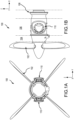
FIGS. 1A and 1B illustrate, a front view, in a y-direction, and a side view, in an x-direction, of a forward portion of a turboprop engine, in accordance with various embodiments. -
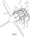
FIG. 2 illustrates an isometric view of a turboprop engine onto which a set of engine carcass stiffeners are affixed, in accordance with various embodiment. -
FIG. 3 illustrates an isometric view of an exhaust engine carcass of a turboprop engine onto which a set of engine carcass stiffeners are affixed, in accordance with various embodiments. -
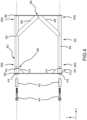
FIG. 4 illustrates an exploded side view of an engine carcass stiffener, in accordance with various embodiments. -
FIG. 5 illustrates a cross-sectional view of a coupling of a first section to the second section of an engine carcass stiffener, in accordance with various embodiments. - The detailed description of embodiments herein makes reference to the accompanying drawings, which show embodiments by way of illustration. While these embodiments are described in sufficient detail to enable those skilled in the art to practice the disclosure, it should be understood that other embodiments may be realized and that logical, chemical, and mechanical changes may be made without departing from the scope of the disclosure. Thus, the detailed description herein is presented for purposes of illustration only and not for limitation. For example, any reference to singular includes plural embodiments, and any reference to more than one component or step may include a singular embodiment or step. Also, any reference to attached, fixed, connected or the like may include permanent, removable, temporary, partial, full and/or any other possible attachment option. Further, any steps in a method discussed herein may be performed in any suitable order or combination. Additionally, any reference to without contact (or similar phrases) may also include reduced contact or minimal contact. It should also be understood that unless specifically stated otherwise, references to "a," "an," or "the" may include one or more than one and that reference to an item in the singular may also include the item in the plural. Further, all ranges may include upper and lower values and all ranges and ratio limits disclosed herein may be combined.
- As used herein, "aft" refers to the direction associated with the tail (e.g., the back end) of an aircraft, or generally, to the direction of exhaust of the gas turbine. As used herein, "forward" refers to the direction associated with the nose (e.g., the front end) of an aircraft, or generally, to the direction of flight or motion, or to the direction associated with the inlet of the gas turbine engine. As utilized herein, radially inward refers to the negative R direction (towards axis A-A') and radially outward refers to the R direction (away from the A-A' axis). An A-R-C (axial, radial, circumferential) axis is shown in various drawings to illustrate the relative position of various components.
- Disclosed herein is an engine carcass stiffener that structurally reinforces and minimizes deflection of the exhaust engine carcass in a turboprop engine. In various embodiments, the engine carcass stiffener may be installed on either side of an exhaust engine carcass, hereinafter referred to as an exhaust engine carcass. In various embodiments, each engine carcass stiffener includes a first section and a second section. In various embodiments, the first section, which may be coupled to an aft portion of the exhaust engine carcass, includes a set of longitudinal reinforcement members, i.e. a first longitudinal reinforcement member and a second longitudinal reinforcement member. In various embodiments, the first longitudinal reinforcement member is spaced, in a z-direction, a distance from the second longitudinal reinforcement member such that the first longitudinal reinforcement member and the second longitudinal reinforcement member are disposed proximate to either side of an exhaust port that protrudes through a portion of the exhaust engine carcass. In various embodiments, the first section includes a proximal flange that couples to a proximal flange of the exhaust engine carcass, the proximal flange of the exhaust engine carcass further coupled to a distal flange of a gas generator case. In various embodiments, a proximal end of each of the first longitudinal reinforcement member and the second longitudinal reinforcement member couple to the proximal flange of the first section at radially or axially opposite ends, in the z-direction, of the proximal flange of the first section. In various embodiments, the first section further includes a set of cross-support members. In various embodiments, a first end of each of the cross-support members are coupled to the proximal flange of the first section at an area between the radially or axially opposite ends of the proximal flange of the first section and are respectively coupled to an area of the first longitudinal reinforcement member or the second longitudinal reinforcement member between the proximal end and the distal end of the first longitudinal reinforcement member or the second longitudinal reinforcement member.
- In various embodiments, the second section of the engine carcass stiffener includes a distal flange that couples to a distal flange of the exhaust engine carcass, the distal flange of the exhaust engine carcass further coupled to a proximal flange of the gear box. In various embodiments, the distal flange of the second section includes a set of bushing holders, which each have a tubular shape with a void in the center in order to receive a bushing. In various embodiments, the bushing holders are disposed at radially or axially opposite ends of the distal flange of the second section. In various embodiments, each of the set of bushing holders may be structurally supported and affixed to the distal flange of the second section by a support that is coupled to a side of the bushing holder and coupled to the distal flange of the second section. In various embodiments, a respective bushing may be disposed within each of the set of bushing holders. In various embodiments, the distal flange of the second section may be coupled to the distal ends of the set of longitudinal reinforcement members via a respective bolt that is fitted into a respective sliding pin that is fitted into a respective bushing within a respective bushing holder. In that regard, in various embodiments, each distal end of the set of longitudinal reinforcement members includes a female threaded portion so as to receive the male threaded portion of a respective bolt. In various embodiments, each sliding pin is longer in length longitudinally than a longitudinal length of the respective bushing and bushing holder into which the sliding pin is fitted. In that regard, in various embodiments, once the respective bolt is tightened into a respective one of the set of longitudinal reinforcement members with the respective sliding pin positioned between the head of the bolt and the distal end of the respective one of the set of longitudinal reinforcement members, the distal flange of the second section is configured to slide in an axial direction, i.e. in the x-direction, along a respective sliding pin. In that regard, responsive to an axial expansion of the exhaust engine carcass that may occur when the exhaust engine carcass heats up during operation, the second section of the engine carcass stiffener slides along the sliding pins while providing structurally reinforcement and minimizing deflection of the exhaust engine carcass.
- With reference to
FIGS. 1A and 1B , a front view, in a y-direction, and a side view, in an x-direction, of a forward portion of aturboprop engine 100 is illustrated, in accordance with various embodiments. In various embodiments, theturboprop engine 100 generally includes apropeller 102, agear box section 104, anexhaust engine carcass 106, and agas generator casing 108. In various embodiments, theexhaust engine carcass 106 includes a set ofexhaust ports 110 disposed on either side, in a y-direction, of theexhaust engine carcass 106. - Referring to
FIG. 2 , an isometric view of aturboprop engine 100 onto which a set ofengine carcass stiffeners 200 are affixed is illustrated, in accordance with various embodiments. In various embodiments, theturboprop engine 100 generally includes thepropeller 102, thegearbox section 104, theexhaust engine carcass 106, and thegas generator casing 108. In various embodiments, theexhaust engine carcass 106 includes the set ofexhaust ports 110 disposed on either side, in a y-direction, of theexhaust engine carcass 106. In various embodiments, during operation of theturboprop engine 100, various maneuvers, may cause deflection in at least theexhaust engine carcass 106 due to the structure of theexhaust engine carcass 106. In that regard, in various embodiments, theengine carcass stiffeners 200 are added to either side of theexhaust engine carcass 106 to structurally reinforce and tend to minimize deflection of theexhaust engine carcass 106, i.e. an exhaust engine carcass, of theturboprop engine 100. In various embodiments, theengine carcass stiffener 200 includes afirst section 202 and asecond section 204. In various embodiments, thefirst section 202 includes a proximal flange that couples to a proximal flange of theexhaust engine carcass 106, the proximal flange of theexhaust engine carcass 106 further coupled to a distal flange of agas generator casing 108. In various embodiments, thesecond section 204 includes a distal flange that couples to a distal flange of theexhaust engine carcass 106, the distal flange of theexhaust engine carcass 106 further coupled to a proximal flange of thegear box section 104. In various embodiments, thefirst section 202 is then coupled to thesecond section 204. - Referring to
FIG. 3 , an isometric view of theexhaust engine carcass 106 of theturboprop engine 100 onto which a set ofengine carcass stiffeners 200 are affixed is illustrated, in accordance with various embodiments. As described previously, in various embodiments, anengine carcass stiffener 200 includes thefirst section 202 and thesecond section 204. In various embodiments, thefirst section 202 includes aproximal flange 306 that couples to aproximal flange 310 of theexhaust engine carcass 106, theproximal flange 310 of theexhaust engine carcass 106 further coupled to adistal flange 312 of thegas generator casing 108. In various embodiments, thesecond section 204 includes adistal flange 308 that that couples to adistal flange 314 of theexhaust engine carcass 106, thedistal flange 314 of theexhaust engine carcass 106 further coupled to aproximal flange 316 of thegear box section 104. In various embodiments, thefirst section 202 is then coupled to thesecond section 204. - Referring to
FIG. 4 , an exploded side view of anengine carcass stiffener 200 is illustrated, in accordance with various embodiments. In various embodiments, eachengine carcass stiffener 200 includes thefirst section 202 and asecond section 204. In various embodiments, the first section includes a set oflongitudinal reinforcement members longitudinal reinforcement member 402 and a secondlongitudinal reinforcement member 404. In various embodiments, the firstlongitudinal reinforcement member 402 is spaced, in a z-direction, a distance from the secondlongitudinal reinforcement member 404 such that the firstlongitudinal reinforcement member 402 and the secondlongitudinal reinforcement member 404 are disposed proximate to either side of an exhaust ports that protrudes through a portion of the exhaust engine carcass as illustrated inFIGS. 2 and3 . In various embodiments, thefirst section 202 includes aproximal flange 306 that couples to a proximal flange of the exhaust engine carcass. In various embodiments,proximal end longitudinal reinforcement member 402 and the secondlongitudinal reinforcement member 404 couple to theproximal flange 306 at radially or axially opposite ends, in the z-direction, of theproximal flange 306. In various embodiments, thefirst section 202 further includes a set ofcross-support members cross-support members proximal flange 306 at anarea 426 between the radially or axially opposite ends of theproximal flange 306. In various embodiments, set ofcross-support members longitudinal reinforcement member 402 or the secondlongitudinal reinforcement member 404 between theproximal end distal end longitudinal reinforcement member 402 or the secondlongitudinal reinforcement member 404. In various embodiments, thecross-support members longitudinal reinforcement member 402 and the secondlongitudinal reinforcement member 404 between theproximal end distal end longitudinal reinforcement member 402 and the secondlongitudinal reinforcement member 404 and further curves around the exhaust port. In various embodiments, thecross-support members longitudinal reinforcement member 402 and the secondlongitudinal reinforcement member 404 as well as theproximal flange 306 and further curves around the exhaust port. - In various embodiments, the
second section 204 of the engine carcass stiffener includes adistal flange 308 that couples to a distal flange of the exhaust engine carcass. In various embodiments, thedistal flange 308 includes a set ofbushing holders first bushing holder 410 and asecond bushing holder 412. In various embodiments, the ofbushing holders bushing holder distal flange 308. In various embodiments, each of the set ofbushing holders distal flange 308 by astructural support 414 that is coupled to a side of thebushing holder distal flange 308. In various embodiments, structural support may be a piece of metal with a defined thickness that is triangular or square, among others in shape that may be welded, or otherwise affixed to a side of thebushing holder distal flange 308. In various embodiments, arespective bushing bushing holders distal flange 308 may be coupled to the distal ends 402b, 404b of the set oflongitudinal reinforcement members respective bolt 420 that is fitted into a respective slidingpin 422 that is fitted into arespective bushing distal end longitudinal reinforcement members respective bolt 420. - In various embodiments, each sliding
pin 422 is longer in length longitudinally than a longitudinal length of therespective bushing bushing holder pin 422 is fitted. In that regard, in various embodiments, once therespective bolt 420 is inserted through arespective bushing bushing holder distal end longitudinal reinforcement members pin 422 positioned between the head of thebolt 420 and the respectivedistal end longitudinal reinforcement members distal flange 308 of thesecond section 204 is configured to slide in an axial direction, i.e. in the x-direction, along a respective slidingpin 422. In that regard, responsive to an axial expansion of the exhaust engine carcass that may occur when the exhaust engine carcass heats up during operation, thesecond section 204 of theengine carcass stiffener 200 slides along the slidingpins 422 while providing structurally reinforcement and minimizing deflection of the exhaust engine carcass. In various embodiments, the various components of theengine carcass stiffener 200 may be manufactured from nickel-chromium alloy 625 (a nickel-based superalloy), nickel alloy 718 (a nickel-based superalloy), waspaloy (a nickel-based, age hardenable superalloy), Haynes" 282® (a nickel-chromium-cobalt superalloy), or other superalloy, among others, that each have high strength, excellent fabricability (including joining), and outstanding corrosion resistance. In various embodiments, the set oflongitudinal reinforcement members cross-support members - Referring to
FIG. 5 , a cross-sectional view of a coupling of afirst section 202 to asecond section 204 of anengine carcass stiffener 200 is illustrated, in accordance with various embodiments. In various embodiments, thedistal flange 308 may be coupled to the distal ends 402b of the firstlongitudinal reinforcement member 402 via arespective bolt 420 that is fitted into slidingpin 422 that is fitted into thebushing 416 within thebushing holder 410. In that regard, in various embodiments, thedistal end 402b of the firstlongitudinal reinforcement member 402 includes a female threaded portion so as to receive the male threaded portion of arespective bolt 420. In various embodiments, the slidingpin 422 is longer in length longitudinally than a longitudinal length of thebushing 416 andbushing holder 410 into which the slidingpin 422 is fitted. In that regard, in various embodiments, once thebolt 420 is tightened into thedistal end 402b of the firstlongitudinal reinforcement member 402 with the slidingpin 422 positioned between the head of thebolt 420 and thedistal end 402b of the firstlongitudinal reinforcement member 402, thedistal flange 308 is configured to slide in an axial direction, i.e. in the x-direction, along the slidingpin 422. In that regard, responsive to an axial expansion of the exhaust engine carcass that may occur when the exhaust engine carcass heats up during operation, thesecond section 204 of the engine carcass stiffener slides along the slidingpin 422 while providing structural reinforcement and tending to minimize deflection of the exhaust engine carcass. - Benefits and other advantages have been described herein with regard to specific embodiments. Furthermore, the connecting lines shown in the various figures contained herein are intended to represent exemplary functional relationships and/or physical couplings between the various elements. It should be noted that many alternative or additional functional relationships or physical connections may be present in a practical system. However, the benefits, advantages, solutions to problems, and any elements that may cause any benefit, advantage, or solution to occur or become more pronounced are not to be construed as critical, required, or essential features or elements of the disclosure. The scope of the invention is accordingly to be limited by nothing other than the appended claims, in which reference to an element in the singular is not intended to mean "one and only one" unless explicitly so stated, but rather "one or more." Moreover, where a phrase similar to "at least one of A, B, or C" is used in the claims, it is intended that the phrase be interpreted to mean that A alone may be present in an embodiment, B alone may be present in an embodiment, C alone may be present in an embodiment, or that any combination of the elements A, B and C may be present in a single embodiment; for example, A and B, A and C, B and C, or A and B and C.
- Systems, methods, and apparatus are provided herein. In the detailed description herein, references to "one embodiment," "an embodiment," "an example embodiment," etc., indicate that the embodiment described may include a particular feature, structure, or characteristic, but every embodiment may not necessarily include the particular feature, structure, or characteristic. Moreover, such phrases are not necessarily referring to the same embodiment. Further, when a particular feature, structure, or characteristic is described in connection with an embodiment, it is submitted that it is within the knowledge of one skilled in the art to affect such feature, structure, or characteristic in connection with other embodiments whether or not explicitly described. After reading the description, it will be apparent to one skilled in the relevant art(s) how to implement the invention in alternative embodiments.
- Furthermore, no element, component, or method step in the present invention is intended to be dedicated to the public regardless of whether the element, component, or method step is explicitly recited in the claims. As used herein, the terms "comprises," "comprising," or any other variation thereof, are intended to cover a non-exclusive inclusion, such that a process, method, article, or apparatus that comprises a list of elements does not include only those elements but may include other elements not expressly listed or inherent to such process, method, article, or apparatus.
Claims (12)
- An engine carcass stiffener (200) for a turboprop engine (100), the engine carcass stiffener (200) comprising:a proximal flange (306);a first longitudinal reinforcement member (402), wherein a proximal end (402a) of the first longitudinal reinforcement member (402) is coupled to a first end of the proximal flange (306);a second longitudinal reinforcement member (404), wherein a proximal end (404a) of the second longitudinal reinforcement member (404) is coupled to a second end of the proximal flange (306);a distal flange (308);a first bushing holder (410), wherein the first bushing holder (410) is coupled to a first end of the distal flange (308);a second bushing holder (412), wherein the second bushing holder (412) is coupled to a second end of the distal flange (308);a first bolt (420), wherein the first bolt (420) is inserted through the first bushing holder (410) and couples to a distal end (402b) of the first longitudinal reinforcement member (402); anda second bolt (420), wherein the second bolt (420) is inserted through the second bushing holder (412) and couples to a distal end (404b) of the second longitudinal reinforcement member (404).
- The engine carcass stiffener (200) of claim 1, further comprising:a first bushing (416) fitted into the first bushing holder (410), wherein the first bolt (420) is inserted through the first bushing (416); anda second bushing (418) fitted into the second bushing holder (412), wherein the second bolt (420) is inserted through the second bushing (418).
- The engine carcass stiffener (200) of claim 2, further comprising:a first sliding pin (422) fitted into the first bushing (416),wherein the first bolt (420) is inserted through the first sliding pin (422) ; anda second sliding pin (422) fitted into the second bushing (418), wherein the second bolt (420) is inserted through the second sliding pin (422).
- The engine carcass stiffener (200) of claim 3, wherein the distal flange (308) is configured to slide along the first sliding pin (422) and the second sliding pin (422).
- The engine carcass stiffener (200) of claim 3 or 4, wherein the first sliding pin (422) is longer in length longitudinally than a longitudinal length of the first bushing (416) and the first bushing holder (410) and the second sliding pin (422) is longer in length longitudinally than a longitudinal length of the second bushing (418) and the second bushing holder (412).
- The engine carcass stiffener (200) of any preceding claim, further comprising:a first cross-support member (406), wherein a first end of the first cross-support member (406) is coupled to the proximal flange (306) at an area (426) between the first and second ends of the proximal flange (306), and a second end of the first cross-support member (406) is coupled to the first longitudinal reinforcement member (402) at an area between the proximal end (402a) and the distal end (402b) of the first longitudinal reinforcement member (402); anda second cross-support member (408), wherein a first end of the second cross-support member is coupled to the proximal flange (306) at the area (426) between the first and second ends of the proximal flange (306), and a second end of the second cross-support member is coupled to the second longitudinal reinforcement member (404) at an area between the proximal end (404a) and the distal end (404b) of the second longitudinal reinforcement member (404).
- The engine carcass stiffener (200) of any preceding claim, further comprising:a first structural support (414), wherein the first structural support (414) is coupled to a side of the first bushing holder (410) and the first structural support (414) is further coupled to the distal flange (308); anda second structural support (414), wherein the second structural support (414) is coupled to a side of the second bushing holder (412) and the second structural support (414) is further coupled to the distal flange (308).
- The engine carcass stiffener (200) of any preceding claim, wherein the distal end (402b) of the first longitudinal reinforcement member (402) comprises female threads configured to receive male threads of the first bolt (420) and the distal end (404b) of the second longitudinal reinforcement member (404) comprises female threads configured to receive male threads of the second bolt (420).
- The engine carcass stiffener (200) of any preceding claim, wherein the first longitudinal reinforcement member (402) is spaced a distance from the second longitudinal reinforcement member (404) and the distance is dependent on a diameter of an exhaust port (110).
- The engine carcass stiffener (200) of claim 9, wherein the first longitudinal reinforcement member (402) and the second longitudinal reinforcement member (404) are disposed proximate to either side of the exhaust port (110).
- The engine carcass stiffener (200) of any preceding claim, wherein the engine carcass stiffener (200) is manufactured from a superalloy.
- A turboprop engine (100) comprising the engine carcass stiffener (200) according to any preceding claim.
Applications Claiming Priority (1)
| Application Number | Priority Date | Filing Date | Title |
|---|---|---|---|
| US18/459,939 US12270313B2 (en) | 2023-09-01 | 2023-09-01 | Engine carcass stiffener for high maneuver loads |
Publications (1)
| Publication Number | Publication Date |
|---|---|
| EP4517058A1 true EP4517058A1 (en) | 2025-03-05 |
Family
ID=92632694
Family Applications (1)
| Application Number | Title | Priority Date | Filing Date |
|---|---|---|---|
| EP24197744.6A Pending EP4517058A1 (en) | 2023-09-01 | 2024-08-30 | Engine carcass stiffener for high maneuver loads |
Country Status (3)
| Country | Link |
|---|---|
| US (1) | US12270313B2 (en) |
| EP (1) | EP4517058A1 (en) |
| CA (1) | CA3252687A1 (en) |
Citations (5)
| Publication number | Priority date | Publication date | Assignee | Title |
|---|---|---|---|---|
| US2965338A (en) * | 1956-04-09 | 1960-12-20 | Rolls Royce | Engine mounting |
| FR3039824A1 (en) * | 2015-08-07 | 2017-02-10 | Snecma | KIT FOR GUIDING AN AIRCRAFT TURBOMACHINE DURING ITS INSTALLATION / REMOVAL ALONG A CRIB |
| CN106414241A (en) * | 2013-11-18 | 2017-02-15 | 洛德公司 | Turboprop engine attachment systems and methods |
| US9738392B2 (en) * | 2013-01-21 | 2017-08-22 | Snecma | Suspension structure with variable geometry of a turboprop engine on a structural element of an aircraft |
| EP3344544B1 (en) * | 2015-09-04 | 2022-07-06 | LORD Corporation | Anti-torque aft-mounting systems, devices, and methods for turboprop/turboshaft engines |
Family Cites Families (9)
| Publication number | Priority date | Publication date | Assignee | Title |
|---|---|---|---|---|
| CN1989316A (en) | 2004-05-17 | 2007-06-27 | 小L·詹姆士·卡尔达雷拉 | Turbine Case Stiffeners in Gas Turbine Jet Engines |
| US20120195752A1 (en) | 2011-02-01 | 2012-08-02 | General Electric Company | Stiffening system for steam turbine casing |
| US10788046B2 (en) | 2018-01-05 | 2020-09-29 | Hamilton Sundstrand Corporation | Fan and compressor housing for an air cycle machine |
| FR3090696B1 (en) * | 2018-12-21 | 2020-12-04 | Safran | SUPERALALLY TURBINE PART COMPRISING RHENIUM AND / OR RUTHENIUM AND ASSOCIATED MANUFACTURING PROCESS |
| JP7258131B2 (en) * | 2019-05-30 | 2023-04-14 | 三菱電機株式会社 | CONNECTION MANAGEMENT DEVICE, CONNECTION MANAGEMENT SYSTEM, CONNECTION MANAGEMENT METHOD AND PROGRAM |
| GB202018430D0 (en) * | 2020-11-24 | 2021-01-06 | Rolls Royce Plc | Support assembly for gas turbine engine |
| US11746664B2 (en) | 2021-09-23 | 2023-09-05 | Raytheon Technologies Corporation | Geared gas turbine engine with front section moment stiffness relationships |
| US11486271B1 (en) * | 2021-10-15 | 2022-11-01 | Pratt & Whitney Canada Corp. | Adjustable mount for engine accessory |
| US12158076B1 (en) | 2023-07-07 | 2024-12-03 | Pratt & Whitney Canada Corp. | Local stiffening for gas turbine engine casing |
-
2023
- 2023-09-01 US US18/459,939 patent/US12270313B2/en active Active
-
2024
- 2024-08-20 CA CA3252687A patent/CA3252687A1/en active Pending
- 2024-08-30 EP EP24197744.6A patent/EP4517058A1/en active Pending
Patent Citations (5)
| Publication number | Priority date | Publication date | Assignee | Title |
|---|---|---|---|---|
| US2965338A (en) * | 1956-04-09 | 1960-12-20 | Rolls Royce | Engine mounting |
| US9738392B2 (en) * | 2013-01-21 | 2017-08-22 | Snecma | Suspension structure with variable geometry of a turboprop engine on a structural element of an aircraft |
| CN106414241A (en) * | 2013-11-18 | 2017-02-15 | 洛德公司 | Turboprop engine attachment systems and methods |
| FR3039824A1 (en) * | 2015-08-07 | 2017-02-10 | Snecma | KIT FOR GUIDING AN AIRCRAFT TURBOMACHINE DURING ITS INSTALLATION / REMOVAL ALONG A CRIB |
| EP3344544B1 (en) * | 2015-09-04 | 2022-07-06 | LORD Corporation | Anti-torque aft-mounting systems, devices, and methods for turboprop/turboshaft engines |
Also Published As
| Publication number | Publication date |
|---|---|
| CA3252687A1 (en) | 2025-06-04 |
| US20250075638A1 (en) | 2025-03-06 |
| US12270313B2 (en) | 2025-04-08 |
Similar Documents
| Publication | Publication Date | Title |
|---|---|---|
| US10280768B2 (en) | Turbine blisk including ceramic matrix composite blades and methods of manufacture | |
| EP3730739A1 (en) | Turbine assembly for a gas turbine engine with ceramic matrix composite vane | |
| EP3489463B1 (en) | Composite fan platform lug reinforcement | |
| EP3225792A1 (en) | Attachment system between a strut and an engine casing | |
| EP3396251A1 (en) | Fuel swirler with anit-rotation features | |
| EP3029272A1 (en) | Nozzle support systems | |
| US20210199124A1 (en) | Fan blade having closed metal sheath | |
| US7429166B2 (en) | Methods and apparatus for gas turbine engines | |
| US12270313B2 (en) | Engine carcass stiffener for high maneuver loads | |
| EP3260739B1 (en) | Low-cost epicyclic gear carrier and method of making the same | |
| US10934861B2 (en) | Turbine wheel assembly with pinned ceramic matrix composite blades | |
| EP3434597A1 (en) | Nacelle | |
| EP3730738B1 (en) | Turbine assembly for a gas turbine engine with ceramic matrix composite vane | |
| EP3296515A2 (en) | Anti-rotation stator vane assembly | |
| EP3081761A1 (en) | Mid-turbine frame and gas turbine with a mid-turbine frame | |
| US20200340363A1 (en) | Turbine section assembly with ceramic matrix composite vane | |
| EP2910752B1 (en) | Fuel manifold fitting with integral support for a gas turbine engine and method of mounting a fuel supply manifold assembly | |
| US20260009344A1 (en) | Turbine exhaust case and bearing housing assembly | |
| EP3252294B1 (en) | Toroidal spinner aft flange | |
| EP3101228B1 (en) | Flow splitting baffle | |
| EP3690253B1 (en) | Spline insertion feature for assembly and damage improvement | |
| US12467387B1 (en) | Turbine exhaust case structural flange | |
| US12618342B1 (en) | Turbine exhaust case with stiffening brace | |
| US20210123355A1 (en) | System for an improved stator assembly |
Legal Events
| Date | Code | Title | Description |
|---|---|---|---|
| PUAI | Public reference made under article 153(3) epc to a published international application that has entered the european phase |
Free format text: ORIGINAL CODE: 0009012 |
|
| STAA | Information on the status of an ep patent application or granted ep patent |
Free format text: STATUS: THE APPLICATION HAS BEEN PUBLISHED |
|
| AK | Designated contracting states |
Kind code of ref document: A1 Designated state(s): AL AT BE BG CH CY CZ DE DK EE ES FI FR GB GR HR HU IE IS IT LI LT LU LV MC ME MK MT NL NO PL PT RO RS SE SI SK SM TR |
|
| STAA | Information on the status of an ep patent application or granted ep patent |
Free format text: STATUS: REQUEST FOR EXAMINATION WAS MADE |
|
| 17P | Request for examination filed |
Effective date: 20250905 |