EP3296515A2 - Anti-rotation stator vane assembly - Google Patents
Anti-rotation stator vane assembly Download PDFInfo
- Publication number
- EP3296515A2 EP3296515A2 EP17185642.0A EP17185642A EP3296515A2 EP 3296515 A2 EP3296515 A2 EP 3296515A2 EP 17185642 A EP17185642 A EP 17185642A EP 3296515 A2 EP3296515 A2 EP 3296515A2
- Authority
- EP
- European Patent Office
- Prior art keywords
- aft
- slot
- flange
- rotation lug
- vane
- Prior art date
- Legal status (The legal status is an assumption and is not a legal conclusion. Google has not performed a legal analysis and makes no representation as to the accuracy of the status listed.)
- Granted
Links
- 239000007789 gas Substances 0.000 description 15
- 238000000034 method Methods 0.000 description 12
- 238000009434 installation Methods 0.000 description 8
- 230000000712 assembly Effects 0.000 description 6
- 238000000429 assembly Methods 0.000 description 6
- 230000008901 benefit Effects 0.000 description 6
- 239000000567 combustion gas Substances 0.000 description 3
- 230000000295 complement effect Effects 0.000 description 3
- 239000000284 extract Substances 0.000 description 3
- 230000008569 process Effects 0.000 description 3
- 239000002826 coolant Substances 0.000 description 2
- 230000008878 coupling Effects 0.000 description 2
- 238000010168 coupling process Methods 0.000 description 2
- 238000005859 coupling reaction Methods 0.000 description 2
- 239000000446 fuel Substances 0.000 description 2
- 230000036961 partial effect Effects 0.000 description 2
- 230000000903 blocking effect Effects 0.000 description 1
- 238000004891 communication Methods 0.000 description 1
- 230000006835 compression Effects 0.000 description 1
- 238000007906 compression Methods 0.000 description 1
- 230000012447 hatching Effects 0.000 description 1
- 230000000670 limiting effect Effects 0.000 description 1
- 239000000463 material Substances 0.000 description 1
- 230000009467 reduction Effects 0.000 description 1
- 230000002829 reductive effect Effects 0.000 description 1
- 230000004044 response Effects 0.000 description 1
- 230000000717 retained effect Effects 0.000 description 1
- 230000003068 static effect Effects 0.000 description 1
- 239000000126 substance Substances 0.000 description 1
Images


Classifications
-
- F—MECHANICAL ENGINEERING; LIGHTING; HEATING; WEAPONS; BLASTING
- F04—POSITIVE - DISPLACEMENT MACHINES FOR LIQUIDS; PUMPS FOR LIQUIDS OR ELASTIC FLUIDS
- F04D—NON-POSITIVE-DISPLACEMENT PUMPS
- F04D29/00—Details, component parts, or accessories
- F04D29/60—Mounting; Assembling; Disassembling
- F04D29/64—Mounting; Assembling; Disassembling of axial pumps
- F04D29/644—Mounting; Assembling; Disassembling of axial pumps especially adapted for elastic fluid pumps
-
- F—MECHANICAL ENGINEERING; LIGHTING; HEATING; WEAPONS; BLASTING
- F01—MACHINES OR ENGINES IN GENERAL; ENGINE PLANTS IN GENERAL; STEAM ENGINES
- F01D—NON-POSITIVE DISPLACEMENT MACHINES OR ENGINES, e.g. STEAM TURBINES
- F01D25/00—Component parts, details, or accessories, not provided for in, or of interest apart from, other groups
- F01D25/24—Casings; Casing parts, e.g. diaphragms, casing fastenings
- F01D25/246—Fastening of diaphragms or stator-rings
-
- F—MECHANICAL ENGINEERING; LIGHTING; HEATING; WEAPONS; BLASTING
- F01—MACHINES OR ENGINES IN GENERAL; ENGINE PLANTS IN GENERAL; STEAM ENGINES
- F01D—NON-POSITIVE DISPLACEMENT MACHINES OR ENGINES, e.g. STEAM TURBINES
- F01D9/00—Stators
- F01D9/02—Nozzles; Nozzle boxes; Stator blades; Guide conduits, e.g. individual nozzles
- F01D9/04—Nozzles; Nozzle boxes; Stator blades; Guide conduits, e.g. individual nozzles forming ring or sector
- F01D9/042—Nozzles; Nozzle boxes; Stator blades; Guide conduits, e.g. individual nozzles forming ring or sector fixing blades to stators
-
- F—MECHANICAL ENGINEERING; LIGHTING; HEATING; WEAPONS; BLASTING
- F04—POSITIVE - DISPLACEMENT MACHINES FOR LIQUIDS; PUMPS FOR LIQUIDS OR ELASTIC FLUIDS
- F04D—NON-POSITIVE-DISPLACEMENT PUMPS
- F04D29/00—Details, component parts, or accessories
- F04D29/40—Casings; Connections of working fluid
- F04D29/52—Casings; Connections of working fluid for axial pumps
- F04D29/522—Casings; Connections of working fluid for axial pumps especially adapted for elastic fluid pumps
-
- F—MECHANICAL ENGINEERING; LIGHTING; HEATING; WEAPONS; BLASTING
- F04—POSITIVE - DISPLACEMENT MACHINES FOR LIQUIDS; PUMPS FOR LIQUIDS OR ELASTIC FLUIDS
- F04D—NON-POSITIVE-DISPLACEMENT PUMPS
- F04D29/00—Details, component parts, or accessories
- F04D29/40—Casings; Connections of working fluid
- F04D29/52—Casings; Connections of working fluid for axial pumps
- F04D29/54—Fluid-guiding means, e.g. diffusers
- F04D29/541—Specially adapted for elastic fluid pumps
- F04D29/542—Bladed diffusers
-
- F—MECHANICAL ENGINEERING; LIGHTING; HEATING; WEAPONS; BLASTING
- F05—INDEXING SCHEMES RELATING TO ENGINES OR PUMPS IN VARIOUS SUBCLASSES OF CLASSES F01-F04
- F05D—INDEXING SCHEME FOR ASPECTS RELATING TO NON-POSITIVE-DISPLACEMENT MACHINES OR ENGINES, GAS-TURBINES OR JET-PROPULSION PLANTS
- F05D2230/00—Manufacture
- F05D2230/60—Assembly methods
-
- F—MECHANICAL ENGINEERING; LIGHTING; HEATING; WEAPONS; BLASTING
- F05—INDEXING SCHEMES RELATING TO ENGINES OR PUMPS IN VARIOUS SUBCLASSES OF CLASSES F01-F04
- F05D—INDEXING SCHEME FOR ASPECTS RELATING TO NON-POSITIVE-DISPLACEMENT MACHINES OR ENGINES, GAS-TURBINES OR JET-PROPULSION PLANTS
- F05D2240/00—Components
- F05D2240/10—Stators
- F05D2240/12—Fluid guiding means, e.g. vanes
- F05D2240/128—Nozzles
- F05D2240/1281—Plug nozzles
-
- F—MECHANICAL ENGINEERING; LIGHTING; HEATING; WEAPONS; BLASTING
- F05—INDEXING SCHEMES RELATING TO ENGINES OR PUMPS IN VARIOUS SUBCLASSES OF CLASSES F01-F04
- F05D—INDEXING SCHEME FOR ASPECTS RELATING TO NON-POSITIVE-DISPLACEMENT MACHINES OR ENGINES, GAS-TURBINES OR JET-PROPULSION PLANTS
- F05D2240/00—Components
- F05D2240/80—Platforms for stationary or moving blades
Definitions
- the present disclosure relates to a gas turbine engine and, more specifically, to a stator vane assembly.
- Gas turbine engines typically include a fan section, a compressor section, a combustor section and a turbine section.
- air is pressurized in the compressor section and is mixed with fuel and burned in the combustor section to generate hot combustion gases.
- the hot combustion gases flow through the turbine section, which extracts energy from the hot combustion gases to power the compressor section and other gas turbine engine loads.
- One or more sections of the gas turbine engine may include a plurality of vane assemblies having vanes interspersed between rotor assemblies that carry the blades of successive stages of the section.
- Each vane assembly may comprise a plurality of a vanes installed within an engine case to form an annular structure. Installation of vane assemblies is prone to human error.
- a vane assembly for a gas turbine engine is described herein, in accordance with various embodiments.
- a vane assembly may comprise an engine case and an anti-rotation lug coupled to the engine case.
- the anti-rotation lug may have a forward end and an aft end.
- a vane cluster may be supported within the engine case.
- the vane cluster may include an outer shroud with a first slot defined by a forward flange of the outer shroud and with a second slot defined by an aft flange of the outer shroud.
- the second slot may be configured to receive the aft end of the anti-rotation lug from first direction and wherein the aft flange may be configured to block receipt of the anti-rotation lug from a second direction, which is opposite the first direction.
- a width of the second slot may be less than a width of the anti-rotation lug.
- the second slot may include a tapered opening.
- the aft end of the anti-rotation lug may include a tapered geometry and is configured to fit into the tapered opening of the second slot.
- An aft edge of the aft flange may form an aft wall of the second slot.
- the vane cluster may be positioned adjacent to a radially inner surface of the engine case.
- the first direction may be directed from the forward flange toward the aft flange of the outer shroud.
- the second direction may be directed from the aft flange toward the forward flange of the outer shroud.
- a compressor section is also provided.
- the compressor section may comprise a compressor case and an anti-rotation lug coupled to the compressor case.
- a vane cluster may include an outer shroud supported within the compressor case. The outer shroud may be configured to receive the anti-rotation lug from first direction. The outer shroud may be configured to block receipt of the anti-rotation lug from a second direction, which is opposite the first direction.
- the outer shroud may comprise a forward flange and an aft flange.
- the forward flange may define a first slot and wherein the aft flange defines a second slot comprising a tapered opening.
- the anti-rotation lug may comprise an aft end including a tapered geometry configured to fit into the tapered opening of the second slot.
- An aft edge of the aft flange may form an aft wall of the second slot.
- the first direction may be directed from the forward flange toward the aft flange of the outer shroud.
- the second direction may be directed from the aft flange toward the forward flange of the outer shroud.
- the vane cluster may further include a plurality of vanes mounted to an inner shroud.
- a gas turbine engine may comprise an engine section comprising at least one of a compressor section or a fan section.
- the engine section may comprise an engine case and an anti-rotation lug coupled to the engine case.
- the anti-rotation lug may have a forward end and an aft end.
- a vane cluster may be supported within the engine case.
- the vane cluster may include an outer shroud with a first slot defined by a forward flange of the outer shroud and with a second slot defined by an aft flange of the outer shroud.
- the second slot may be configured to receive the aft end of the anti-rotation lug from first direction.
- the aft flange may be configured to block receipt of the anti-rotation lug from a second direction, which is opposite the first direction.
- the forward flange may define the first slot.
- the aft flange may define the second slot comprising a tapered opening.
- the aft end of the anti-rotation lug may comprise a tapered geometry configured to fit into the tapered opening of the second slot.
- the first direction may be directed from the forward flange toward the aft flange of the outer shroud.
- the second direction may be directed from the aft flange toward the forward flange of the outer shroud.
- any reference to attached, fixed, connected, or the like may include permanent, removable, temporary, partial, full, and/or any other possible attachment option. Additionally, any reference to without contact (or similar phrases) may also include reduced contact or minimal contact.
- Cross hatching lines may be used throughout the figures to denote different parts but not necessarily to denote the same or different materials.
- tail refers to the direction associated with the tail (e.g., the back end) of an aircraft, or generally, to the direction of exhaust of the gas turbine engine.
- forward refers to the direction associated with the nose (e.g., the front end) of an aircraft, or generally, to the direction of flight or motion.
- distal refers to the direction radially outward, or generally, away from the axis of rotation of a turbine engine.
- proximal refers to a direction radially inward, or generally, towards the axis of rotation of a turbine engine.
- Gas-turbine engine 20 may be a two-spool turbofan that generally incorporates a fan section 22, a compressor section 24, a combustor section 26 and a turbine section 28.
- Alternative engines may include, for example, an augmentor section among other systems or features.
- fan section 22 can drive coolant along a bypass flow path B while compressor section 24 can drive coolant along a core flow path C for compression and communication into combustor section 26 then expansion through turbine section 28.
- turbofan gas-turbine engine 20 depicted as a turbofan gas-turbine engine 20 herein, it should be understood that the concepts described herein are not limited to use with turbofans as the teachings may be applied to other types of turbine engines including three-spool architectures.
- Gas-turbine engine 20 may generally comprise a low speed spool 30 and a high speed spool 32 mounted for rotation about an engine central longitudinal axis A-A' relative to an engine static structure or engine case structure 36 via several bearing systems 38, 38-1, and 38-2. It should be understood that various bearing systems 38 at various locations may alternatively or additionally be provided, including for example, bearing system 38, bearing system 38-1, and bearing system 38-2.
- Low speed spool 30 may generally comprise an inner shaft 40 that interconnects a fan 42, a low pressure compressor section 44 and a low pressure turbine section 46.
- Inner shaft 40 may be connected to fan 42 through a geared architecture 48 that can drive fan 42 at a lower speed than low speed spool 30.
- Geared architecture 48 may comprise a gear assembly 60 enclosed within a gear housing 62.
- Gear assembly 60 couples inner shaft 40 to a rotating fan structure.
- High speed spool 32 may comprise an outer shaft 50 that interconnects a high pressure compressor 52 and high pressure turbine 54.
- a combustor 56 may be located between high pressure compressor 52 and high pressure turbine 54.
- a mid-turbine frame 57 of engine case structure 36 may be located generally between high pressure turbine 54 and low pressure turbine 46.
- Mid-turbine frame 57 may support one or more bearing systems 38 in turbine section 28.
- Inner shaft 40 and outer shaft 50 may be concentric and rotate via bearing systems 38 about the engine central longitudinal axis A-A', which is collinear with their longitudinal axes.
- A-A' the engine central longitudinal axis A-A'
- the core airflow C may be compressed by low pressure compressor 44 then high pressure compressor 52, mixed and burned with fuel in combustor 56, then expanded over high pressure turbine 54 and low pressure turbine 46.
- Turbines 46, 54 rotationally drive the respective low speed spool 30 and high speed spool 32 in response to the expansion.
- Gas-turbine engine 20 may be, for example, a high-bypass ratio geared aircraft engine. In various embodiments, the bypass ratio of gas-turbine engine 20 may be greater than about six (6). In various embodiments, the bypass ratio of gas-turbine engine 20 may be greater than ten (10).
- geared architecture 48 may be an epicyclic gear train, such as a star gear system (sun gear in meshing engagement with a plurality of star gears supported by a carrier and in meshing engagement with a ring gear) or other gear system. Geared architecture 48 may have a gear reduction ratio of greater than about 2.3 and low pressure turbine 46 may have a pressure ratio that is greater than about five (5).
- the bypass ratio of gas-turbine engine 20 is greater than about ten (10:1).
- the diameter of fan 42 may be significantly larger than that of the low pressure compressor 44, and the low pressure turbine 46 may have a pressure ratio that is greater than about five (5:1).
- Low pressure turbine 46 pressure ratio may be measured prior to inlet of low pressure turbine 46 as related to the pressure at the outlet of low pressure turbine 46 prior to an exhaust nozzle. It should be understood, however, that the above parameters are exemplary of various embodiments of a suitable geared architecture engine and that the present disclosure contemplates other turbine engines including direct drive turbofans.
- a gas turbine engine may comprise an industrial gas turbine (IGT) or a geared aircraft engine, such as a geared turbofan, or non-geared aircraft engine, such as a turbofan, a turboshaft, or may comprise any gas turbine engine as desired.
- IGT industrial gas turbine
- a geared aircraft engine such as a geared turbofan, or non-geared aircraft engine, such as a turbofan, a turboshaft, or may comprise
- an engine section such as fan section 22, compressor section 24 and/or turbine section 28, may comprise one or more stages or sets of rotating blades and one or more stages or sets of stationary vanes axially interspersed with the associated blade stages but non-rotating about engine central longitudinal axis A-A'.
- the rotor assemblies may carry a plurality of rotating blades, while each vane assembly 100 may carry a plurality of vanes that extend into the core flow path C.
- the blades may rotate about engine central longitudinal axis A-A', while the vanes may remain stationary about engine central longitudinal axis A-A'.
- the blades may create or extract energy (in the form of pressure) from the core airflow that is communicated through the engine section along the core flow path C.
- the vanes may direct the core airflow to the blades to either add or extract energy.
- a plurality of vane assemblies 100 may be disposed throughout the core flow path C to impart desirable flow characteristics on the gas flowing through the core flow path C. Vane assemblies 100 may at least one row of vanes arranged circumferentially about the engine central longitudinal axis A-A'.
- a vane assembly 100 may include a plurality of vanes 110, which may be arranged into subassemblies or vane clusters 112.
- a vane assembly 100 may include a partial or a complete circumferential array of vanes 110.
- vane assembly 100 may comprise a continuous annular vane assembly or a plurality of vane clusters 112.
- each vane 110 may be a separate component from each adjacent vane 110.
- Vanes 110 may be grouped into vane clusters 112 and arranged circumferential about engine central longitudinal axis A-A' to provide the vane assembly 100.
- Vanes 110 and/or vane clusters 112 may be mounted in circumferentially abutting relationship to form an annular ring.
- Each of the vanes 110 may comprise a leading edge 114 and a trailing edge 116. Leading edge 114 and trailing edge 116 may be configured to direct airflow through gas-turbine engine 20.
- a vane 110 may comprise, for example, an airfoil body 120. Vane 110 may comprise a radially outer end 122 and a radially inner end 124 with airfoil body 120 extending between radially outer end 122 and radially inner end 124. Radially outer end 122 may be a distal end of vane 110. Radially inner end 124 may be a proximal end of vane 110. A distance between radially outer end 122 and radially inner end 124 may, for example, comprise a span of airfoil body 120.
- each vane 110 of vane assembly 100 may be circumferentially retained to the engine at an outer diameter and/or an inner diameter of the vane assembly 100.
- Vanes 110 may be cantilevered with an attachment point at radially inner end 124 or at radially outer end 122.
- a radially inner end 124 of vane 110 may couple to an inner shroud 130.
- Vane assembly 100 may include an inner shroud 130, which may be an inner circumferential fixed structure comprised of one or more segments.
- a plurality of vanes 110 may be coupled to a segment of inner shroud 130 to form a vane cluster 112.
- Radially outer end 122 of vane 110 may couple an outer shroud 132.
- vane 110 may be integral with a portion of inner shroud 130 or outer shroud 132.
- each vane 110 may include a discrete portion of outer shroud 132 integral with the vane 110.
- each vane cluster 112 may include a plurality of vanes 110 forming a portion of outer shroud 132, and vanes 110 of the vane cluster 112 may be coupled to a segment of inner shroud 130.
- one or more vane clusters 112 are disposed within and supported by an engine case 140.
- Engine case 140 may be an aft case of a compressor, i.e., a compressor case, for example.
- Engine case 140 may have an annular geometry configured to receive a plurality of vane clusters 112 positioned adjacent to a radially inner surface 142 of engine case 140.
- Vane cluster 112 may be slidably received within engine case 140.
- An anti-rotation lug 144 may interface with outer shroud 132 to prevent undesired circumferential movement or rotation of vane clusters 112 relative to engine case 140.
- Anti-rotation lug 144 may fit into a slot 134 in outer shroud 132. Slot 134 and anti-rotation lug 144 may be configured with an installation feature, as described herein.
- Anti-rotation lug 144 may be coupled to radially inner surface 142 of engine case 140, for example, by a fastener 150.
- Fastener 150 may include a bolt, washer, pin, screw, rivet or other suitable fastener for mechanically coupling anti-rotation lug 144 to engine case 140.
- anti-rotation lug 144 may be fixedly attached to or integrally formed with engine case 140.
- Anti-rotation lug 144 may be positioned on engine case 140 to extend in the axial direction (z direction) and may terminate in a forward end 146 and an aft end 148.
- a geometry or shape of forward end 146 of anti-rotation lug 144 may be dissimilar to a geometry or shape of aft end 148 of anti-rotation lug 144.
- aft end 148 of anti-rotation lug 144 may include a tapered surface 160, while forward end 146 of anti-rotation lug 144 may comprise a generally square, or non-tapered, geometry.
- Vane cluster 112 may include an outer shroud 132 disposed at a radially outer end 122 of vanes 110.
- Outer shroud 132 may include a platform 170 with a forward flange 172 and an aft flange 174 extending from platform 170.
- Forward flange 172 may extend axially forward (i.e., in the negative z direction) from platform 170 and may define a first slot 134a.
- First slot 134a may extend into forward flange 172 and may have sidewalls 180, 182 which may be substantially parallel.
- Aft flange 174 may extend axially aft (i.e., in the positive z direction) from platform 170 and may define a second slot 134b.
- Second slot 134b may extend into aft flange 174 and may have sidewalls 184, 186, which may be non-parallel.
- Second slot 134b may comprise a tapered opening, which narrows toward an aft end of second slot 134b.
- an installation feature for a vane assembly may include anti-rotation lug 144, which interfaces with slots 134a, 134b in outer shroud 132.
- Slots 134a, 134b may be configured with complementary geometry to anti-rotation lug 144.
- First slot 134a may have a similar width and similar geometry as forward end 146 of anti-rotation lug 144.
- a width 190 of forward end 146 FIG. 3A
- a width 192 of first slot 134a FIG. 3B
- width 192 is a distance between sidewall 180 and sidewall 182.
- First slot 134a may have a width 192 that is greater than a width 194 of aft end 148, such that aft end 148 may slide through first slot 134a during assembly.
- Second slot 134b may have a similar width and similar geometry as aft end 148 of anti-rotation lug 144.
- a width 196 of second slot 134b ( FIG. 3B ) may be similar to a width 194 of aft end 148 ( FIG. 3A ).
- First slot 134a may be configured to receive anti-rotation lug 144 from a first direction D1, wherein the first direction D1 is directed from the forward flange 172 toward the aft flange 174 of outer shroud 132.
- First slot 134a may further be configured to block receipt of anti-rotation lug 144 from a second direction D2, which is opposite to first direction D1, wherein "opposite to first direction D1" in this context only means 180 degrees opposed to first direction D1, +/- 5 degrees.
- the direction D2 may be directed from aft flange 174 toward forward flange 172 of outer shroud 132 (i.e., in the negative z direction).
- Vane cluster 212 may include a plurality of vanes 210 coupled to an outer shroud 232.
- Outer shroud 232 may include a platform 270 with a forward flange 272 and an aft flange 274 extending from platform 270.
- Forward flange 272 may include a first slot 234a, which may have sidewalls that are substantially parallel.
- Aft flange 274 may include a second slot 234b, which extends in an axial direction (z direction) partially, but not completely, through aft flange 274.
- An aft edge 236 of aft flange 274 may form an aft wall of second slot 234b.
- a vane assembly may include an anti-rotation lug with a geometry complementary to the shape and size of slots 234a, 234b.
- the aft edge 236 of aft flange 274 blocks an anti-rotation lug from being inserted through aft flange 274, thereby preventing vane cluster 212 from being installed backward into an engine case, i.e., with an aft edge positioned forward.
- Vane cluster 312 may include a plurality of vanes 310 coupled to an outer shroud 332.
- Outer shroud 332 may include a platform 370 with a forward flange 372 and an aft flange 374 extending from platform 370.
- Forward flange 372 may include a first slot 334, which may have sidewalls that are substantially parallel.
- Aft flange 374 may not include a slot, and thus aft flange 374 may not receive an anti-rotation lug, such as anti-rotation lug 144 from FIG. 3A .
- a vane assembly may include an anti-rotation lug configured to fit through first slot 334.
- An anti-rotation lug may be configured with a geometry complementary to the shape and size of first slot 334. Without an aft slot, aft flange 374 prevents an anti-rotation lug from being inserted through aft flange 374, thereby preventing vane cluster 312 from being installed backward into an engine case, i.e., with an aft edge positioned forward.
- Anti-rotation lug 144 is configured to interface with outer shroud 132, such that vane cluster 112 is prevented from being installed backwards, i.e., with aft flange 174 positioned forward (negative z direction) relative to forward flange 172.
- a width of second slot 134b may be less than a width of anti-rotation lug 144.
- second slot 134b of aft flange 174 includes a narrow opening that does not receive anti-rotation lug 144 if vane cluster 112 is installed in the wrong direction.
- Second slot 134b is configured to receive the aft end 148 of anti-rotation lug 144 in a first direction, while aft flange 174 is configured to block receipt of the anti-rotation lug 144 in a second direction (shown), which is opposite the first direction.
- a width of second slot 134b is configured to prevent improper installation of vane cluster 112.
- vane assembly 100 with a vane cluster 112 installed within engine case 140 is shown in accordance with various embodiments.
- first slot 134a in forward flange 172 is oriented in a forward direction assembly (negative z direction)
- vane cluster 112 may be slidably received within engine case 140.
- Vane cluster 112 may be configured to interface with an engine case 140 via forward flange 172, wherein engine case 140 is disposed radially outward or distal to vane cluster 112.
- Forward flange 172 may be configured to couple within one or more slots 200 defined within engine case 140.
- Vane assembly 100 may receive a plurality of vane clusters 112 within engine case 140 and may include on or more anti-rotation lugs 144.
- Each vane cluster 112 may be configured to receive an anti-rotation lug 144 from first direction, such as with forward flange 172 oriented in a forward direction with respect to vane cluster 112 within engine case 140.
- Aft flange 174 may be configured to block receipt of anti-rotation lug 144 from a second direction, such as with forward flange 172 oriented in an aft direction with respect to vane cluster 112 within engine case 140.
- Engine case 140 provides the support for the vane cluster 112 such that loads on vane cluster 112 transfer to the engine case 140.
- Method 400 may comprise the steps of inserting a vane cluster into an engine case having an anti-rotation lug (step 402), receiving, by the vane cluster, the anti-rotation lug from a first direction (step 404), blocking receipt of the anti-rotation lug from a second direction, which is opposite the first direction (step 406).
- references to "various embodiments”, “one embodiment”, “an embodiment”, “an example embodiment”, etc. indicate that the embodiment described may include a particular feature, structure, or characteristic, but every embodiment may not necessarily include the particular feature, structure, or characteristic. Moreover, such phrases are not necessarily referring to the same embodiment. Further, when a particular feature, structure, or characteristic is described in connection with an embodiment, it is submitted that it is within the knowledge of one skilled in the art to affect such feature, structure, or characteristic in connection with other embodiments whether or not explicitly described. After reading the description, it will be apparent to one skilled in the relevant art(s) how to implement the disclosure in alternative embodiments.
Abstract
Description
- The present disclosure relates to a gas turbine engine and, more specifically, to a stator vane assembly.
- Gas turbine engines typically include a fan section, a compressor section, a combustor section and a turbine section. In general, during operation, air is pressurized in the compressor section and is mixed with fuel and burned in the combustor section to generate hot combustion gases. The hot combustion gases flow through the turbine section, which extracts energy from the hot combustion gases to power the compressor section and other gas turbine engine loads. One or more sections of the gas turbine engine may include a plurality of vane assemblies having vanes interspersed between rotor assemblies that carry the blades of successive stages of the section. Each vane assembly may comprise a plurality of a vanes installed within an engine case to form an annular structure. Installation of vane assemblies is prone to human error.
- A vane assembly for a gas turbine engine is described herein, in accordance with various embodiments. A vane assembly may comprise an engine case and an anti-rotation lug coupled to the engine case. The anti-rotation lug may have a forward end and an aft end. A vane cluster may be supported within the engine case. The vane cluster may include an outer shroud with a first slot defined by a forward flange of the outer shroud and with a second slot defined by an aft flange of the outer shroud. The second slot may be configured to receive the aft end of the anti-rotation lug from first direction and wherein the aft flange may be configured to block receipt of the anti-rotation lug from a second direction, which is opposite the first direction.
- In various embodiments, a width of the second slot may be less than a width of the anti-rotation lug. The second slot may include a tapered opening. The aft end of the anti-rotation lug may include a tapered geometry and is configured to fit into the tapered opening of the second slot. An aft edge of the aft flange may form an aft wall of the second slot. The vane cluster may be positioned adjacent to a radially inner surface of the engine case. The first direction may be directed from the forward flange toward the aft flange of the outer shroud. The second direction may be directed from the aft flange toward the forward flange of the outer shroud.
- A compressor section is also provided. The compressor section may comprise a compressor case and an anti-rotation lug coupled to the compressor case. A vane cluster may include an outer shroud supported within the compressor case. The outer shroud may be configured to receive the anti-rotation lug from first direction. The outer shroud may be configured to block receipt of the anti-rotation lug from a second direction, which is opposite the first direction.
- In various embodiments, the outer shroud may comprise a forward flange and an aft flange. The forward flange may define a first slot and wherein the aft flange defines a second slot comprising a tapered opening. The anti-rotation lug may comprise an aft end including a tapered geometry configured to fit into the tapered opening of the second slot. An aft edge of the aft flange may form an aft wall of the second slot. The first direction may be directed from the forward flange toward the aft flange of the outer shroud. The second direction may be directed from the aft flange toward the forward flange of the outer shroud. The vane cluster may further include a plurality of vanes mounted to an inner shroud.
- A gas turbine engine is also provided. The gas turbine engine may comprise an engine section comprising at least one of a compressor section or a fan section. The engine section may comprise an engine case and an anti-rotation lug coupled to the engine case. The anti-rotation lug may have a forward end and an aft end. A vane cluster may be supported within the engine case. The vane cluster may include an outer shroud with a first slot defined by a forward flange of the outer shroud and with a second slot defined by an aft flange of the outer shroud. The second slot may be configured to receive the aft end of the anti-rotation lug from first direction. The aft flange may be configured to block receipt of the anti-rotation lug from a second direction, which is opposite the first direction.
- In various embodiments, the forward flange may define the first slot. The aft flange may define the second slot comprising a tapered opening. The aft end of the anti-rotation lug may comprise a tapered geometry configured to fit into the tapered opening of the second slot. The first direction may be directed from the forward flange toward the aft flange of the outer shroud. The second direction may be directed from the aft flange toward the forward flange of the outer shroud.
- The foregoing features and elements may be combined in various combinations without exclusivity, unless expressly indicated otherwise. These features and elements as well as the operation thereof will become more apparent in light of the following description and the accompanying drawings. It should be understood, however, the following description and drawings are intended to be exemplary in nature and non-limiting.
- The subject matter of the present disclosure is particularly pointed out and distinctly claimed in the concluding portion of the specification. A more complete understanding of the present disclosure, however, may best be obtained by referring to the detailed description and claims when considered in connection with the figures, wherein like numerals denote like elements.
-
FIG. 1 illustrates a cross-sectional view of an exemplary gas turbine engine, in accordance with various embodiments; -
FIG. 2 illustrates a fragmentary perspective view of a vane assembly of a gas turbine engine, in accordance with various embodiments; -
FIG. 3A illustrates an inner surface of an engine case of a vane assembly, in accordance with various embodiments; and -
FIGS. 3B ,3C , and3D illustrate an outer view of a vane cluster for a vane assembly, in accordance with various embodiments; -
FIG. 4 illustrates an installation feature of a vane assembly, in accordance with various embodiments; -
FIG. 5 illustrates a fragmentary perspective view of a vane assembly of a gas turbine engine, in accordance with various embodiments; and -
FIG. 6 illustrates a method installing a vane cluster, in accordance with various embodiments. - All ranges and ratio limits disclosed herein may be combined. It is to be understood that unless specifically stated otherwise, references to "a," "an," and/or "the" may include one or more than one and that reference to an item in the singular may also include the item in the plural.
- The detailed description of various embodiments herein makes reference to the accompanying drawings, which show various embodiments by way of illustration. While these various embodiments are described in sufficient detail to enable those skilled in the art to practice the disclosure, it should be understood that other embodiments may be realized and that logical, chemical, and mechanical changes may be made without departing from the spirit and scope of the disclosure. Thus, the detailed description herein is presented for purposes of illustration only and not of limitation. For example, the steps recited in any of the method or process descriptions may be executed in any order and are not necessarily limited to the order presented. Furthermore, any reference to singular includes plural embodiments, and any reference to more than one component or step may include a singular embodiment or step. Also, any reference to attached, fixed, connected, or the like may include permanent, removable, temporary, partial, full, and/or any other possible attachment option. Additionally, any reference to without contact (or similar phrases) may also include reduced contact or minimal contact. Cross hatching lines may be used throughout the figures to denote different parts but not necessarily to denote the same or different materials.
- As used herein, "aft" refers to the direction associated with the tail (e.g., the back end) of an aircraft, or generally, to the direction of exhaust of the gas turbine engine. As used herein, "forward" refers to the direction associated with the nose (e.g., the front end) of an aircraft, or generally, to the direction of flight or motion.
- As used herein, "distal" refers to the direction radially outward, or generally, away from the axis of rotation of a turbine engine. As used herein, "proximal" refers to a direction radially inward, or generally, towards the axis of rotation of a turbine engine.
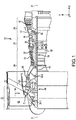
- In various embodiments and with reference to
FIG. 1 , a gas-turbine engine 20 is provided. Gas-turbine engine 20 may be a two-spool turbofan that generally incorporates afan section 22, acompressor section 24, acombustor section 26 and aturbine section 28. Alternative engines may include, for example, an augmentor section among other systems or features. In operation,fan section 22 can drive coolant along a bypass flow path B whilecompressor section 24 can drive coolant along a core flow path C for compression and communication intocombustor section 26 then expansion throughturbine section 28. Although depicted as a turbofan gas-turbine engine 20 herein, it should be understood that the concepts described herein are not limited to use with turbofans as the teachings may be applied to other types of turbine engines including three-spool architectures. - Gas-
turbine engine 20 may generally comprise alow speed spool 30 and ahigh speed spool 32 mounted for rotation about an engine central longitudinal axis A-A' relative to an engine static structure orengine case structure 36 viaseveral bearing systems 38, 38-1, and 38-2. It should be understood that various bearingsystems 38 at various locations may alternatively or additionally be provided, including for example, bearingsystem 38, bearing system 38-1, and bearing system 38-2. -
Low speed spool 30 may generally comprise aninner shaft 40 that interconnects afan 42, a lowpressure compressor section 44 and a lowpressure turbine section 46.Inner shaft 40 may be connected to fan 42 through a gearedarchitecture 48 that can drivefan 42 at a lower speed thanlow speed spool 30.Geared architecture 48 may comprise agear assembly 60 enclosed within agear housing 62.Gear assembly 60 couplesinner shaft 40 to a rotating fan structure.High speed spool 32 may comprise anouter shaft 50 that interconnects ahigh pressure compressor 52 andhigh pressure turbine 54. Acombustor 56 may be located betweenhigh pressure compressor 52 andhigh pressure turbine 54. Amid-turbine frame 57 ofengine case structure 36 may be located generally betweenhigh pressure turbine 54 andlow pressure turbine 46.Mid-turbine frame 57 may support one ormore bearing systems 38 inturbine section 28.Inner shaft 40 andouter shaft 50 may be concentric and rotate via bearingsystems 38 about the engine central longitudinal axis A-A', which is collinear with their longitudinal axes. As used herein, a "high pressure" compressor or turbine experiences a higher pressure than a corresponding "low pressure" compressor or turbine. - The core airflow C may be compressed by
low pressure compressor 44 thenhigh pressure compressor 52, mixed and burned with fuel incombustor 56, then expanded overhigh pressure turbine 54 andlow pressure turbine 46.Turbines low speed spool 30 andhigh speed spool 32 in response to the expansion. - Gas-
turbine engine 20 may be, for example, a high-bypass ratio geared aircraft engine. In various embodiments, the bypass ratio of gas-turbine engine 20 may be greater than about six (6). In various embodiments, the bypass ratio of gas-turbine engine 20 may be greater than ten (10). In various embodiments, gearedarchitecture 48 may be an epicyclic gear train, such as a star gear system (sun gear in meshing engagement with a plurality of star gears supported by a carrier and in meshing engagement with a ring gear) or other gear system.Geared architecture 48 may have a gear reduction ratio of greater than about 2.3 andlow pressure turbine 46 may have a pressure ratio that is greater than about five (5). In various embodiments, the bypass ratio of gas-turbine engine 20 is greater than about ten (10:1). In various embodiments, the diameter offan 42 may be significantly larger than that of thelow pressure compressor 44, and thelow pressure turbine 46 may have a pressure ratio that is greater than about five (5:1).Low pressure turbine 46 pressure ratio may be measured prior to inlet oflow pressure turbine 46 as related to the pressure at the outlet oflow pressure turbine 46 prior to an exhaust nozzle. It should be understood, however, that the above parameters are exemplary of various embodiments of a suitable geared architecture engine and that the present disclosure contemplates other turbine engines including direct drive turbofans. A gas turbine engine may comprise an industrial gas turbine (IGT) or a geared aircraft engine, such as a geared turbofan, or non-geared aircraft engine, such as a turbofan, a turboshaft, or may comprise any gas turbine engine as desired. - In various embodiments, an engine section, such as
fan section 22,compressor section 24 and/orturbine section 28, may comprise one or more stages or sets of rotating blades and one or more stages or sets of stationary vanes axially interspersed with the associated blade stages but non-rotating about engine central longitudinal axis A-A'. For example, the rotor assemblies may carry a plurality of rotating blades, while eachvane assembly 100 may carry a plurality of vanes that extend into the core flow path C. The blades may rotate about engine central longitudinal axis A-A', while the vanes may remain stationary about engine central longitudinal axis A-A'. The blades may create or extract energy (in the form of pressure) from the core airflow that is communicated through the engine section along the core flow path C. The vanes may direct the core airflow to the blades to either add or extract energy. A plurality ofvane assemblies 100 may be disposed throughout the core flow path C to impart desirable flow characteristics on the gas flowing through the core flow pathC. Vane assemblies 100 may at least one row of vanes arranged circumferentially about the engine central longitudinal axis A-A'. - Referring to
FIGS. 1 and2 , avane assembly 100 may include a plurality ofvanes 110, which may be arranged into subassemblies orvane clusters 112. Avane assembly 100 may include a partial or a complete circumferential array ofvanes 110. In various embodiments,vane assembly 100 may comprise a continuous annular vane assembly or a plurality ofvane clusters 112. In various embodiments, eachvane 110 may be a separate component from eachadjacent vane 110.Vanes 110 may be grouped intovane clusters 112 and arranged circumferential about engine central longitudinal axis A-A' to provide thevane assembly 100.Vanes 110 and/orvane clusters 112 may be mounted in circumferentially abutting relationship to form an annular ring. - With reference now to
FIG. 2 , a portion of avane assembly 100 ofFIG. 1 is shown, in accordance with various embodiments. Each of thevanes 110 may comprise aleading edge 114 and a trailingedge 116. Leadingedge 114 and trailingedge 116 may be configured to direct airflow through gas-turbine engine 20. Avane 110 may comprise, for example, anairfoil body 120.Vane 110 may comprise a radiallyouter end 122 and a radiallyinner end 124 withairfoil body 120 extending between radiallyouter end 122 and radiallyinner end 124. Radiallyouter end 122 may be a distal end ofvane 110. Radiallyinner end 124 may be a proximal end ofvane 110. A distance between radiallyouter end 122 and radiallyinner end 124 may, for example, comprise a span ofairfoil body 120. - In various embodiments, each
vane 110 ofvane assembly 100 may be circumferentially retained to the engine at an outer diameter and/or an inner diameter of thevane assembly 100.Vanes 110 may be cantilevered with an attachment point at radiallyinner end 124 or at radiallyouter end 122. A radiallyinner end 124 ofvane 110 may couple to aninner shroud 130.Vane assembly 100 may include aninner shroud 130, which may be an inner circumferential fixed structure comprised of one or more segments. In various embodiments, a plurality ofvanes 110 may be coupled to a segment ofinner shroud 130 to form avane cluster 112. Radiallyouter end 122 ofvane 110 may couple anouter shroud 132. In various embodiments,vane 110 may be integral with a portion ofinner shroud 130 orouter shroud 132. For example, eachvane 110 may include a discrete portion ofouter shroud 132 integral with thevane 110. Thus, eachvane cluster 112 may include a plurality ofvanes 110 forming a portion ofouter shroud 132, andvanes 110 of thevane cluster 112 may be coupled to a segment ofinner shroud 130. - In various embodiments, one or
more vane clusters 112 are disposed within and supported by anengine case 140.Engine case 140 may be an aft case of a compressor, i.e., a compressor case, for example.Engine case 140 may have an annular geometry configured to receive a plurality ofvane clusters 112 positioned adjacent to a radiallyinner surface 142 ofengine case 140.Vane cluster 112 may be slidably received withinengine case 140. Ananti-rotation lug 144 may interface withouter shroud 132 to prevent undesired circumferential movement or rotation ofvane clusters 112 relative toengine case 140.Anti-rotation lug 144 may fit into aslot 134 inouter shroud 132.Slot 134 andanti-rotation lug 144 may be configured with an installation feature, as described herein. - With reference now to
FIG. 3A , anengine case 140 including ananti-rotation lug 144 is shown, in accordance with various embodiments.Anti-rotation lug 144 may be coupled to radiallyinner surface 142 ofengine case 140, for example, by afastener 150.Fastener 150 may include a bolt, washer, pin, screw, rivet or other suitable fastener for mechanically couplinganti-rotation lug 144 toengine case 140. In various embodiments,anti-rotation lug 144 may be fixedly attached to or integrally formed withengine case 140. -
Anti-rotation lug 144 may be positioned onengine case 140 to extend in the axial direction (z direction) and may terminate in aforward end 146 and anaft end 148. A geometry or shape offorward end 146 ofanti-rotation lug 144 may be dissimilar to a geometry or shape ofaft end 148 ofanti-rotation lug 144. In various embodiments,aft end 148 ofanti-rotation lug 144 may include atapered surface 160, whileforward end 146 ofanti-rotation lug 144 may comprise a generally square, or non-tapered, geometry. - With reference to
FIG. 3B , a portion of avane cluster 112 is shown, in accordance with various embodiments.Vane cluster 112 may include anouter shroud 132 disposed at a radiallyouter end 122 ofvanes 110.Outer shroud 132 may include aplatform 170 with aforward flange 172 and anaft flange 174 extending fromplatform 170.Forward flange 172 may extend axially forward (i.e., in the negative z direction) fromplatform 170 and may define afirst slot 134a.First slot 134a may extend intoforward flange 172 and may have sidewalls 180, 182 which may be substantially parallel.Aft flange 174 may extend axially aft (i.e., in the positive z direction) fromplatform 170 and may define asecond slot 134b.Second slot 134b may extend intoaft flange 174 and may have sidewalls 184, 186, which may be non-parallel.Second slot 134b may comprise a tapered opening, which narrows toward an aft end ofsecond slot 134b. - Referring now to
FIGS. 3A and3B , an installation feature for a vane assembly may includeanti-rotation lug 144, which interfaces withslots outer shroud 132.Slots anti-rotation lug 144.First slot 134a may have a similar width and similar geometry asforward end 146 ofanti-rotation lug 144. For example, awidth 190 of forward end 146 (FIG. 3A ) may be similar to awidth 192 offirst slot 134a (FIG. 3B ), whereinwidth 192 is a distance betweensidewall 180 andsidewall 182.First slot 134a may have awidth 192 that is greater than awidth 194 ofaft end 148, such thataft end 148 may slide throughfirst slot 134a during assembly.Second slot 134b may have a similar width and similar geometry asaft end 148 ofanti-rotation lug 144. For example, awidth 196 ofsecond slot 134b (FIG. 3B ) may be similar to awidth 194 of aft end 148 (FIG. 3A ).First slot 134a may be configured to receiveanti-rotation lug 144 from a first direction D1, wherein the first direction D1 is directed from theforward flange 172 toward theaft flange 174 ofouter shroud 132.First slot 134a may further be configured to block receipt ofanti-rotation lug 144 from a second direction D2, which is opposite to first direction D1, wherein "opposite to first direction D1" in this context only means 180 degrees opposed to first direction D1, +/- 5 degrees. The direction D2 may be directed fromaft flange 174 towardforward flange 172 of outer shroud 132 (i.e., in the negative z direction). - With reference to
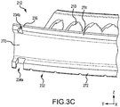
FIG. 3C , a portion of avane cluster 212 including anouter shroud 232 having an installation feature is shown in accordance with various embodiments.Vane cluster 212 may include a plurality ofvanes 210 coupled to anouter shroud 232.Outer shroud 232 may include aplatform 270 with aforward flange 272 and anaft flange 274 extending fromplatform 270.Forward flange 272 may include afirst slot 234a, which may have sidewalls that are substantially parallel.Aft flange 274 may include asecond slot 234b, which extends in an axial direction (z direction) partially, but not completely, throughaft flange 274. Anaft edge 236 ofaft flange 274 may form an aft wall ofsecond slot 234b. A vane assembly may include an anti-rotation lug with a geometry complementary to the shape and size ofslots aft edge 236 ofaft flange 274 blocks an anti-rotation lug from being inserted throughaft flange 274, thereby preventingvane cluster 212 from being installed backward into an engine case, i.e., with an aft edge positioned forward. - With reference to
FIG. 3D , a portion of avane cluster 312 including anouter shroud 332 having an installation feature is shown in accordance with various embodiments.Vane cluster 312 may include a plurality ofvanes 310 coupled to anouter shroud 332.Outer shroud 332 may include aplatform 370 with aforward flange 372 and anaft flange 374 extending fromplatform 370.Forward flange 372 may include afirst slot 334, which may have sidewalls that are substantially parallel.Aft flange 374 may not include a slot, and thusaft flange 374 may not receive an anti-rotation lug, such asanti-rotation lug 144 fromFIG. 3A . A vane assembly may include an anti-rotation lug configured to fit throughfirst slot 334. An anti-rotation lug may be configured with a geometry complementary to the shape and size offirst slot 334. Without an aft slot,aft flange 374 prevents an anti-rotation lug from being inserted throughaft flange 374, thereby preventingvane cluster 312 from being installed backward into an engine case, i.e., with an aft edge positioned forward. - Referring to
FIG. 4 , a portion of avane assembly 100 including an installation feature is shown in accordance with various embodiments.Anti-rotation lug 144 is configured to interface withouter shroud 132, such thatvane cluster 112 is prevented from being installed backwards, i.e., withaft flange 174 positioned forward (negative z direction) relative toforward flange 172. A width ofsecond slot 134b may be less than a width ofanti-rotation lug 144. As shown inFIG. 4 ,second slot 134b ofaft flange 174 includes a narrow opening that does not receiveanti-rotation lug 144 ifvane cluster 112 is installed in the wrong direction.Second slot 134b is configured to receive theaft end 148 ofanti-rotation lug 144 in a first direction, whileaft flange 174 is configured to block receipt of theanti-rotation lug 144 in a second direction (shown), which is opposite the first direction. Thus, a width ofsecond slot 134b is configured to prevent improper installation ofvane cluster 112. - Referring to
FIG. 5 , a portion of avane assembly 100 with avane cluster 112 installed withinengine case 140 is shown in accordance with various embodiments. Wherefirst slot 134a inforward flange 172 is oriented in a forward direction assembly (negative z direction),vane cluster 112 may be slidably received withinengine case 140.Vane cluster 112 may be configured to interface with anengine case 140 viaforward flange 172, whereinengine case 140 is disposed radially outward or distal tovane cluster 112.Forward flange 172 may be configured to couple within one ormore slots 200 defined withinengine case 140.Vane assembly 100 may receive a plurality ofvane clusters 112 withinengine case 140 and may include on or more anti-rotation lugs 144. Eachvane cluster 112 may be configured to receive ananti-rotation lug 144 from first direction, such as withforward flange 172 oriented in a forward direction with respect tovane cluster 112 withinengine case 140.Aft flange 174 may be configured to block receipt ofanti-rotation lug 144 from a second direction, such as withforward flange 172 oriented in an aft direction with respect tovane cluster 112 withinengine case 140.Engine case 140 provides the support for thevane cluster 112 such that loads onvane cluster 112 transfer to theengine case 140. - With reference to
FIG. 6 , amethod 400 for installing a vane cluster is shown in accordance with various embodiments.Method 400 may comprise the steps of inserting a vane cluster into an engine case having an anti-rotation lug (step 402), receiving, by the vane cluster, the anti-rotation lug from a first direction (step 404), blocking receipt of the anti-rotation lug from a second direction, which is opposite the first direction (step 406). - Benefits and other advantages have been described herein with regard to specific embodiments. Furthermore, the connecting lines shown in the various figures contained herein are intended to represent exemplary functional relationships and/or physical couplings between the various elements. It should be noted that many alternative or additional functional relationships or physical connections may be present in a practical system. However, the benefits, advantages, and any elements that may cause any benefit or advantage to occur or become more pronounced are not to be construed as critical, required, or essential features or elements of the disclosure. The scope of the disclosure is accordingly to be limited by nothing other than the appended claims, in which reference to an element in the singular is not intended to mean "one and only one" unless explicitly so stated, but rather "one or more." Moreover, where a phrase similar to "at least one of A, B, or C" is used in the claims, it is intended that the phrase be interpreted to mean that A alone may be present in an embodiment, B alone may be present in an embodiment, C alone may be present in an embodiment, or that any combination of the elements A, B and C may be present in a single embodiment; for example, A and B, A and C, B and C, or A and B and C.
- Systems, methods and apparatus are provided herein. In the detailed description herein, references to "various embodiments", "one embodiment", "an embodiment", "an example embodiment", etc., indicate that the embodiment described may include a particular feature, structure, or characteristic, but every embodiment may not necessarily include the particular feature, structure, or characteristic. Moreover, such phrases are not necessarily referring to the same embodiment. Further, when a particular feature, structure, or characteristic is described in connection with an embodiment, it is submitted that it is within the knowledge of one skilled in the art to affect such feature, structure, or characteristic in connection with other embodiments whether or not explicitly described. After reading the description, it will be apparent to one skilled in the relevant art(s) how to implement the disclosure in alternative embodiments.
- Furthermore, no element, component, or method step in the present disclosure is intended to be dedicated to the public regardless of whether the element, component, or method step is explicitly recited in the claims. No claim element is intended to invoke 35 U.S.C. 112(f) unless the element is expressly recited using the phrase "means for." As used herein, the terms "comprises", "comprising", or any other variation thereof, are intended to cover a non-exclusive inclusion, such that a process, method, article, or apparatus that comprises a list of elements does not include only those elements but may include other elements not expressly listed or inherent to such process, method, article, or apparatus.
Claims (15)
- A vane assembly, comprising:an engine case;an anti-rotation lug coupled to the engine case, the anti-rotation lug having a forward end and an aft end; anda vane cluster supported within the engine case, wherein the vane cluster includes an outer shroud with a first slot defined by a forward flange of the outer shroud and with a second slot defined by an aft flange of the outer shroud;wherein the second slot is configured to receive the aft end of the anti-rotation lug from a first direction and wherein the aft flange is configured to block receipt of the anti-rotation lug from a second direction, which is opposite the first direction.
- The vane assembly of claim 1, wherein a width of the second slot is less than a width of the anti-rotation lug.
- The vane assembly of claim 1 or 2, wherein the second slot includes a tapered opening,
wherein optionally the aft end of the anti-rotation lug includes a tapered geometry and is configured to fit into the tapered opening of the second slot. - The vane assembly of claim 1, 2 or 3, wherein an aft edge of the aft flange forms an aft wall of the second slot.
- The vane assembly of any preceding claim, wherein the vane cluster is positioned adjacent to a radially inner surface of the engine case.
- A compressor section, comprising:a compressor case;an anti-rotation lug coupled to the compressor case; anda vane cluster including an outer shroud supported within the compressor case;wherein the outer shroud is configured to receive the anti-rotation lug from a first direction and wherein the outer shroud is configured to block receipt of the anti-rotation lug from a second direction, which is opposite the first direction.
- The compressor section of claim 6, wherein the outer shroud comprises a forward flange and an aft flange.
- The compressor section of claim 7, wherein the forward flange defines a first slot and wherein the aft flange defines a second slot comprising a tapered opening.
- The compressor section of claim 8, wherein the anti-rotation lug comprises an aft end including a tapered geometry configured to fit into the tapered opening of the second slot.
- The compressor section of claim 8 or 9, wherein an aft edge of the aft flange forms an aft wall of the second slot.
- The compressor section of any of claims 6 to 10, wherein the vane cluster further includes a plurality of vanes mounted to an inner shroud.
- A gas turbine engine, comprising:an engine section comprising at least one of a compressor section or a fan section, the engine section comprising:an engine case,an anti-rotation lug coupled to the engine case, the anti-rotation lug having a forward end and an aft end, anda vane cluster supported within the engine case, wherein the vane cluster includes an outer shroud with a first slot defined by a forward flange of the outer shroud and with a second slot defined by an aft flange of the outer shroud,wherein the second slot is configured to receive the aft end of the anti-rotation lug from a first direction and wherein the aft flange is configured to block receipt of the anti-rotation lug from a second direction, which is opposite the first direction.
- The gas turbine engine of claim 12, wherein the forward flange defines the first slot and wherein the aft flange defines the second slot comprising a tapered opening,
wherein optionally the aft end of the anti-rotation lug comprises a tapered geometry configured to fit into the tapered opening of the second slot. - The vane assembly of any of claims 1 to 5, the compressor section of any of claims 7 to 11, or the gas turbine engine of any of claims 12 or 13, wherein the first direction is directed from the forward flange toward the aft flange of the outer shroud.
- The vane assembly of any of claims 1 to 5 or 14, the compressor section of any of claims 7 to 11 or 14, or the gas turbine engine of any of claims 12 to 14, wherein the second direction is directed from the aft flange toward the forward flange of the outer shroud.
Applications Claiming Priority (1)
| Application Number | Priority Date | Filing Date | Title |
|---|---|---|---|
| US15/270,773 US10465712B2 (en) | 2016-09-20 | 2016-09-20 | Anti-rotation stator vane assembly |
Publications (3)
| Publication Number | Publication Date |
|---|---|
| EP3296515A2 true EP3296515A2 (en) | 2018-03-21 |
| EP3296515A3 EP3296515A3 (en) | 2018-04-11 |
| EP3296515B1 EP3296515B1 (en) | 2021-12-22 |
Family
ID=59579542
Family Applications (1)
| Application Number | Title | Priority Date | Filing Date |
|---|---|---|---|
| EP17185642.0A Active EP3296515B1 (en) | 2016-09-20 | 2017-08-09 | Vane assembly comprising an anti-rotation plug |
Country Status (2)
| Country | Link |
|---|---|
| US (1) | US10465712B2 (en) |
| EP (1) | EP3296515B1 (en) |
Families Citing this family (3)
| Publication number | Priority date | Publication date | Assignee | Title |
|---|---|---|---|---|
| US20180142564A1 (en) * | 2016-11-22 | 2018-05-24 | General Electric Company | Combined turbine nozzle and shroud deflection limiter |
| EP4108884A4 (en) * | 2020-02-20 | 2023-11-29 | Kawasaki Jukogyo Kabushiki Kaisha | Assembly structure for compressor of gas turbine engine |
| US11939888B2 (en) * | 2022-06-17 | 2024-03-26 | Rtx Corporation | Airfoil anti-rotation ring and assembly |
Family Cites Families (8)
| Publication number | Priority date | Publication date | Assignee | Title |
|---|---|---|---|---|
| US6409472B1 (en) * | 1999-08-09 | 2002-06-25 | United Technologies Corporation | Stator assembly for a rotary machine and clip member for a stator assembly |
| US7094025B2 (en) | 2003-11-20 | 2006-08-22 | General Electric Company | Apparatus and methods for removing and installing a selected nozzle segment of a gas turbine in an axial direction |
| US8038389B2 (en) | 2006-01-04 | 2011-10-18 | General Electric Company | Method and apparatus for assembling turbine nozzle assembly |
| US9051849B2 (en) * | 2012-02-13 | 2015-06-09 | United Technologies Corporation | Anti-rotation stator segments |
| US20160298647A1 (en) * | 2012-07-24 | 2016-10-13 | General Electric Company | Compressor stator assembly and method of installing |
| US10428832B2 (en) * | 2012-08-06 | 2019-10-01 | United Technologies Corporation | Stator anti-rotation lug |
| US9896971B2 (en) * | 2012-09-28 | 2018-02-20 | United Technologies Corporation | Lug for preventing rotation of a stator vane arrangement relative to a turbine engine case |
| EP3000980A3 (en) | 2014-09-29 | 2016-04-13 | United Technologies Corporation | Hybrid gamma tial alloy component |
-
2016
- 2016-09-20 US US15/270,773 patent/US10465712B2/en active Active
-
2017
- 2017-08-09 EP EP17185642.0A patent/EP3296515B1/en active Active
Non-Patent Citations (1)
| Title |
|---|
| None |
Also Published As
| Publication number | Publication date |
|---|---|
| US10465712B2 (en) | 2019-11-05 |
| EP3296515A3 (en) | 2018-04-11 |
| EP3296515B1 (en) | 2021-12-22 |
| US20180080477A1 (en) | 2018-03-22 |
Similar Documents
| Publication | Publication Date | Title |
|---|---|---|
| US10208602B2 (en) | Asymmetric diffuser opening for film cooling holes | |
| EP3252271A1 (en) | Blade assembly, corresponding fan section and gas turbine engine | |
| EP3026217B1 (en) | Turbine rotor or stator segmented sideplates with anti-rotation | |
| EP3296515B1 (en) | Vane assembly comprising an anti-rotation plug | |
| EP2985421A1 (en) | Assembly, compressor and cooling system | |
| EP3112615B1 (en) | Compressor section with a particular arrangement to hold a vane | |
| EP3388624B1 (en) | Engine section and gas turbine engine | |
| EP3404214B1 (en) | Blade outer air seal assembly and gas turbine engine with such an assembly | |
| US10215037B2 (en) | Contoured retaining ring | |
| EP3453835B1 (en) | Fan exit stator assembly | |
| US20230116394A1 (en) | Tandem blade rotor disk | |
| EP3081748A1 (en) | Seal ring and system comprising said seal ring | |
| EP3597861A1 (en) | Contact coupled airfoil singlets | |
| EP3382147A1 (en) | Asymmetric vane assembly | |
| EP3098387B1 (en) | Installation fault tolerant damper | |
| US20190390688A1 (en) | Gas turbine engine airfoil | |
| US20160356177A1 (en) | Heat shield for a vane assembly of a gas turbine engine | |
| EP3101228B1 (en) | Flow splitting baffle | |
| EP3453836B1 (en) | Stator vane support with anti-rotation features | |
| US11408300B2 (en) | Rotor overspeed protection assembly |
Legal Events
| Date | Code | Title | Description |
|---|---|---|---|
| PUAI | Public reference made under article 153(3) epc to a published international application that has entered the european phase |
Free format text: ORIGINAL CODE: 0009012 |
|
| STAA | Information on the status of an ep patent application or granted ep patent |
Free format text: STATUS: THE APPLICATION HAS BEEN PUBLISHED |
|
| PUAL | Search report despatched |
Free format text: ORIGINAL CODE: 0009013 |
|
| AK | Designated contracting states |
Kind code of ref document: A2 Designated state(s): AL AT BE BG CH CY CZ DE DK EE ES FI FR GB GR HR HU IE IS IT LI LT LU LV MC MK MT NL NO PL PT RO RS SE SI SK SM TR |
|
| AX | Request for extension of the european patent |
Extension state: BA ME |
|
| AK | Designated contracting states |
Kind code of ref document: A3 Designated state(s): AL AT BE BG CH CY CZ DE DK EE ES FI FR GB GR HR HU IE IS IT LI LT LU LV MC MK MT NL NO PL PT RO RS SE SI SK SM TR |
|
| AX | Request for extension of the european patent |
Extension state: BA ME |
|
| RIC1 | Information provided on ipc code assigned before grant |
Ipc: F01D 9/04 20060101AFI20180307BHEP Ipc: F01D 25/24 20060101ALI20180307BHEP |
|
| STAA | Information on the status of an ep patent application or granted ep patent |
Free format text: STATUS: REQUEST FOR EXAMINATION WAS MADE |
|
| 17P | Request for examination filed |
Effective date: 20181002 |
|
| RBV | Designated contracting states (corrected) |
Designated state(s): AL AT BE BG CH CY CZ DE DK EE ES FI FR GB GR HR HU IE IS IT LI LT LU LV MC MK MT NL NO PL PT RO RS SE SI SK SM TR |
|
| STAA | Information on the status of an ep patent application or granted ep patent |
Free format text: STATUS: EXAMINATION IS IN PROGRESS |
|
| STAA | Information on the status of an ep patent application or granted ep patent |
Free format text: STATUS: EXAMINATION IS IN PROGRESS |
|
| 17Q | First examination report despatched |
Effective date: 20201127 |
|
| RAP1 | Party data changed (applicant data changed or rights of an application transferred) |
Owner name: RAYTHEON TECHNOLOGIES CORPORATION |
|
| GRAP | Despatch of communication of intention to grant a patent |
Free format text: ORIGINAL CODE: EPIDOSNIGR1 |
|
| STAA | Information on the status of an ep patent application or granted ep patent |
Free format text: STATUS: GRANT OF PATENT IS INTENDED |
|
| INTG | Intention to grant announced |
Effective date: 20210709 |
|
| GRAS | Grant fee paid |
Free format text: ORIGINAL CODE: EPIDOSNIGR3 |
|
| GRAA | (expected) grant |
Free format text: ORIGINAL CODE: 0009210 |
|
| STAA | Information on the status of an ep patent application or granted ep patent |
Free format text: STATUS: THE PATENT HAS BEEN GRANTED |
|
| AK | Designated contracting states |
Kind code of ref document: B1 Designated state(s): AL AT BE BG CH CY CZ DE DK EE ES FI FR GB GR HR HU IE IS IT LI LT LU LV MC MK MT NL NO PL PT RO RS SE SI SK SM TR |
|
| REG | Reference to a national code |
Ref country code: GB Ref legal event code: FG4D |
|
| REG | Reference to a national code |
Ref country code: CH Ref legal event code: EP |
|
| REG | Reference to a national code |
Ref country code: DE Ref legal event code: R096 Ref document number: 602017051172 Country of ref document: DE |
|
| REG | Reference to a national code |
Ref country code: AT Ref legal event code: REF Ref document number: 1457218 Country of ref document: AT Kind code of ref document: T Effective date: 20220115 |
|
| REG | Reference to a national code |
Ref country code: IE Ref legal event code: FG4D |
|
| REG | Reference to a national code |
Ref country code: LT Ref legal event code: MG9D |
|
| PG25 | Lapsed in a contracting state [announced via postgrant information from national office to epo] |
Ref country code: RS Free format text: LAPSE BECAUSE OF FAILURE TO SUBMIT A TRANSLATION OF THE DESCRIPTION OR TO PAY THE FEE WITHIN THE PRESCRIBED TIME-LIMIT Effective date: 20211222 Ref country code: LT Free format text: LAPSE BECAUSE OF FAILURE TO SUBMIT A TRANSLATION OF THE DESCRIPTION OR TO PAY THE FEE WITHIN THE PRESCRIBED TIME-LIMIT Effective date: 20211222 Ref country code: FI Free format text: LAPSE BECAUSE OF FAILURE TO SUBMIT A TRANSLATION OF THE DESCRIPTION OR TO PAY THE FEE WITHIN THE PRESCRIBED TIME-LIMIT Effective date: 20211222 Ref country code: BG Free format text: LAPSE BECAUSE OF FAILURE TO SUBMIT A TRANSLATION OF THE DESCRIPTION OR TO PAY THE FEE WITHIN THE PRESCRIBED TIME-LIMIT Effective date: 20220322 |
|
| REG | Reference to a national code |
Ref country code: NL Ref legal event code: MP Effective date: 20211222 |
|
| REG | Reference to a national code |
Ref country code: AT Ref legal event code: MK05 Ref document number: 1457218 Country of ref document: AT Kind code of ref document: T Effective date: 20211222 |
|
| PG25 | Lapsed in a contracting state [announced via postgrant information from national office to epo] |
Ref country code: SE Free format text: LAPSE BECAUSE OF FAILURE TO SUBMIT A TRANSLATION OF THE DESCRIPTION OR TO PAY THE FEE WITHIN THE PRESCRIBED TIME-LIMIT Effective date: 20211222 Ref country code: NO Free format text: LAPSE BECAUSE OF FAILURE TO SUBMIT A TRANSLATION OF THE DESCRIPTION OR TO PAY THE FEE WITHIN THE PRESCRIBED TIME-LIMIT Effective date: 20220322 Ref country code: LV Free format text: LAPSE BECAUSE OF FAILURE TO SUBMIT A TRANSLATION OF THE DESCRIPTION OR TO PAY THE FEE WITHIN THE PRESCRIBED TIME-LIMIT Effective date: 20211222 Ref country code: HR Free format text: LAPSE BECAUSE OF FAILURE TO SUBMIT A TRANSLATION OF THE DESCRIPTION OR TO PAY THE FEE WITHIN THE PRESCRIBED TIME-LIMIT Effective date: 20211222 Ref country code: GR Free format text: LAPSE BECAUSE OF FAILURE TO SUBMIT A TRANSLATION OF THE DESCRIPTION OR TO PAY THE FEE WITHIN THE PRESCRIBED TIME-LIMIT Effective date: 20220323 |
|
| PG25 | Lapsed in a contracting state [announced via postgrant information from national office to epo] |
Ref country code: NL Free format text: LAPSE BECAUSE OF FAILURE TO SUBMIT A TRANSLATION OF THE DESCRIPTION OR TO PAY THE FEE WITHIN THE PRESCRIBED TIME-LIMIT Effective date: 20211222 |
|
| PG25 | Lapsed in a contracting state [announced via postgrant information from national office to epo] |
Ref country code: SM Free format text: LAPSE BECAUSE OF FAILURE TO SUBMIT A TRANSLATION OF THE DESCRIPTION OR TO PAY THE FEE WITHIN THE PRESCRIBED TIME-LIMIT Effective date: 20211222 Ref country code: SK Free format text: LAPSE BECAUSE OF FAILURE TO SUBMIT A TRANSLATION OF THE DESCRIPTION OR TO PAY THE FEE WITHIN THE PRESCRIBED TIME-LIMIT Effective date: 20211222 Ref country code: RO Free format text: LAPSE BECAUSE OF FAILURE TO SUBMIT A TRANSLATION OF THE DESCRIPTION OR TO PAY THE FEE WITHIN THE PRESCRIBED TIME-LIMIT Effective date: 20211222 Ref country code: PT Free format text: LAPSE BECAUSE OF FAILURE TO SUBMIT A TRANSLATION OF THE DESCRIPTION OR TO PAY THE FEE WITHIN THE PRESCRIBED TIME-LIMIT Effective date: 20220422 Ref country code: ES Free format text: LAPSE BECAUSE OF FAILURE TO SUBMIT A TRANSLATION OF THE DESCRIPTION OR TO PAY THE FEE WITHIN THE PRESCRIBED TIME-LIMIT Effective date: 20211222 Ref country code: EE Free format text: LAPSE BECAUSE OF FAILURE TO SUBMIT A TRANSLATION OF THE DESCRIPTION OR TO PAY THE FEE WITHIN THE PRESCRIBED TIME-LIMIT Effective date: 20211222 Ref country code: CZ Free format text: LAPSE BECAUSE OF FAILURE TO SUBMIT A TRANSLATION OF THE DESCRIPTION OR TO PAY THE FEE WITHIN THE PRESCRIBED TIME-LIMIT Effective date: 20211222 |
|
| PG25 | Lapsed in a contracting state [announced via postgrant information from national office to epo] |
Ref country code: PL Free format text: LAPSE BECAUSE OF FAILURE TO SUBMIT A TRANSLATION OF THE DESCRIPTION OR TO PAY THE FEE WITHIN THE PRESCRIBED TIME-LIMIT Effective date: 20211222 Ref country code: AT Free format text: LAPSE BECAUSE OF FAILURE TO SUBMIT A TRANSLATION OF THE DESCRIPTION OR TO PAY THE FEE WITHIN THE PRESCRIBED TIME-LIMIT Effective date: 20211222 |
|
| REG | Reference to a national code |
Ref country code: DE Ref legal event code: R097 Ref document number: 602017051172 Country of ref document: DE |
|
| PG25 | Lapsed in a contracting state [announced via postgrant information from national office to epo] |
Ref country code: IS Free format text: LAPSE BECAUSE OF FAILURE TO SUBMIT A TRANSLATION OF THE DESCRIPTION OR TO PAY THE FEE WITHIN THE PRESCRIBED TIME-LIMIT Effective date: 20220422 |
|
| PLBE | No opposition filed within time limit |
Free format text: ORIGINAL CODE: 0009261 |
|
| STAA | Information on the status of an ep patent application or granted ep patent |
Free format text: STATUS: NO OPPOSITION FILED WITHIN TIME LIMIT |
|
| PG25 | Lapsed in a contracting state [announced via postgrant information from national office to epo] |
Ref country code: DK Free format text: LAPSE BECAUSE OF FAILURE TO SUBMIT A TRANSLATION OF THE DESCRIPTION OR TO PAY THE FEE WITHIN THE PRESCRIBED TIME-LIMIT Effective date: 20211222 Ref country code: AL Free format text: LAPSE BECAUSE OF FAILURE TO SUBMIT A TRANSLATION OF THE DESCRIPTION OR TO PAY THE FEE WITHIN THE PRESCRIBED TIME-LIMIT Effective date: 20211222 |
|
| 26N | No opposition filed |
Effective date: 20220923 |
|
| PG25 | Lapsed in a contracting state [announced via postgrant information from national office to epo] |
Ref country code: SI Free format text: LAPSE BECAUSE OF FAILURE TO SUBMIT A TRANSLATION OF THE DESCRIPTION OR TO PAY THE FEE WITHIN THE PRESCRIBED TIME-LIMIT Effective date: 20211222 |
|
| PG25 | Lapsed in a contracting state [announced via postgrant information from national office to epo] |
Ref country code: MC Free format text: LAPSE BECAUSE OF FAILURE TO SUBMIT A TRANSLATION OF THE DESCRIPTION OR TO PAY THE FEE WITHIN THE PRESCRIBED TIME-LIMIT Effective date: 20211222 |
|
| REG | Reference to a national code |
Ref country code: CH Ref legal event code: PL |
|
| PG25 | Lapsed in a contracting state [announced via postgrant information from national office to epo] |
Ref country code: LU Free format text: LAPSE BECAUSE OF NON-PAYMENT OF DUE FEES Effective date: 20220809 Ref country code: LI Free format text: LAPSE BECAUSE OF NON-PAYMENT OF DUE FEES Effective date: 20220831 Ref country code: CH Free format text: LAPSE BECAUSE OF NON-PAYMENT OF DUE FEES Effective date: 20220831 |
|
| REG | Reference to a national code |
Ref country code: BE Ref legal event code: MM Effective date: 20220831 |
|
| PG25 | Lapsed in a contracting state [announced via postgrant information from national office to epo] |
Ref country code: IT Free format text: LAPSE BECAUSE OF FAILURE TO SUBMIT A TRANSLATION OF THE DESCRIPTION OR TO PAY THE FEE WITHIN THE PRESCRIBED TIME-LIMIT Effective date: 20211222 |
|
| P01 | Opt-out of the competence of the unified patent court (upc) registered |
Effective date: 20230520 |
|
| PG25 | Lapsed in a contracting state [announced via postgrant information from national office to epo] |
Ref country code: IE Free format text: LAPSE BECAUSE OF NON-PAYMENT OF DUE FEES Effective date: 20220809 |
|
| PG25 | Lapsed in a contracting state [announced via postgrant information from national office to epo] |
Ref country code: BE Free format text: LAPSE BECAUSE OF NON-PAYMENT OF DUE FEES Effective date: 20220831 |
|
| PGFP | Annual fee paid to national office [announced via postgrant information from national office to epo] |
Ref country code: GB Payment date: 20230720 Year of fee payment: 7 |
|
| PGFP | Annual fee paid to national office [announced via postgrant information from national office to epo] |
Ref country code: FR Payment date: 20230720 Year of fee payment: 7 Ref country code: DE Payment date: 20230720 Year of fee payment: 7 |
|
| PG25 | Lapsed in a contracting state [announced via postgrant information from national office to epo] |
Ref country code: HU Free format text: LAPSE BECAUSE OF FAILURE TO SUBMIT A TRANSLATION OF THE DESCRIPTION OR TO PAY THE FEE WITHIN THE PRESCRIBED TIME-LIMIT; INVALID AB INITIO Effective date: 20170809 |