EP4516704A1 - Eiertransfervorrichtung - Google Patents
Eiertransfervorrichtung Download PDFInfo
- Publication number
- EP4516704A1 EP4516704A1 EP23795993.7A EP23795993A EP4516704A1 EP 4516704 A1 EP4516704 A1 EP 4516704A1 EP 23795993 A EP23795993 A EP 23795993A EP 4516704 A1 EP4516704 A1 EP 4516704A1
- Authority
- EP
- European Patent Office
- Prior art keywords
- egg
- acceleration
- eggs
- tray
- conveyor
- Prior art date
- Legal status (The legal status is an assumption and is not a legal conclusion. Google has not performed a legal analysis and makes no representation as to the accuracy of the status listed.)
- Pending
Links
Images


Classifications
-
- B—PERFORMING OPERATIONS; TRANSPORTING
- B65—CONVEYING; PACKING; STORING; HANDLING THIN OR FILAMENTARY MATERIAL
- B65G—TRANSPORT OR STORAGE DEVICES, e.g. CONVEYORS FOR LOADING OR TIPPING, SHOP CONVEYOR SYSTEMS OR PNEUMATIC TUBE CONVEYORS
- B65G47/00—Article or material-handling devices associated with conveyors; Methods employing such devices
- B65G47/52—Devices for transferring articles or materials between conveyors i.e. discharging or feeding devices
- B65G47/53—Devices for transferring articles or materials between conveyors i.e. discharging or feeding devices between conveyors which cross one another
-
- B—PERFORMING OPERATIONS; TRANSPORTING
- B65—CONVEYING; PACKING; STORING; HANDLING THIN OR FILAMENTARY MATERIAL
- B65G—TRANSPORT OR STORAGE DEVICES, e.g. CONVEYORS FOR LOADING OR TIPPING, SHOP CONVEYOR SYSTEMS OR PNEUMATIC TUBE CONVEYORS
- B65G47/00—Article or material-handling devices associated with conveyors; Methods employing such devices
- B65G47/22—Devices influencing the relative position or the attitude of articles during transit by conveyors
- B65G47/24—Devices influencing the relative position or the attitude of articles during transit by conveyors orientating the articles
- B65G47/244—Devices influencing the relative position or the attitude of articles during transit by conveyors orientating the articles by turning them about an axis substantially perpendicular to the conveying plane
-
- B—PERFORMING OPERATIONS; TRANSPORTING
- B65—CONVEYING; PACKING; STORING; HANDLING THIN OR FILAMENTARY MATERIAL
- B65G—TRANSPORT OR STORAGE DEVICES, e.g. CONVEYORS FOR LOADING OR TIPPING, SHOP CONVEYOR SYSTEMS OR PNEUMATIC TUBE CONVEYORS
- B65G47/00—Article or material-handling devices associated with conveyors; Methods employing such devices
- B65G47/22—Devices influencing the relative position or the attitude of articles during transit by conveyors
- B65G47/24—Devices influencing the relative position or the attitude of articles during transit by conveyors orientating the articles
- B65G47/248—Devices influencing the relative position or the attitude of articles during transit by conveyors orientating the articles by turning over or inverting them
-
- B—PERFORMING OPERATIONS; TRANSPORTING
- B65—CONVEYING; PACKING; STORING; HANDLING THIN OR FILAMENTARY MATERIAL
- B65G—TRANSPORT OR STORAGE DEVICES, e.g. CONVEYORS FOR LOADING OR TIPPING, SHOP CONVEYOR SYSTEMS OR PNEUMATIC TUBE CONVEYORS
- B65G2201/00—Indexing codes relating to handling devices, e.g. conveyors, characterised by the type of product or load being conveyed or handled
- B65G2201/02—Articles
- B65G2201/0202—Agricultural and processed food products
- B65G2201/0208—Eggs
-
- B—PERFORMING OPERATIONS; TRANSPORTING
- B65—CONVEYING; PACKING; STORING; HANDLING THIN OR FILAMENTARY MATERIAL
- B65G—TRANSPORT OR STORAGE DEVICES, e.g. CONVEYORS FOR LOADING OR TIPPING, SHOP CONVEYOR SYSTEMS OR PNEUMATIC TUBE CONVEYORS
- B65G47/00—Article or material-handling devices associated with conveyors; Methods employing such devices
- B65G47/02—Devices for feeding articles or materials to conveyors
- B65G47/04—Devices for feeding articles or materials to conveyors for feeding articles
- B65G47/12—Devices for feeding articles or materials to conveyors for feeding articles from disorderly-arranged article piles or from loose assemblages of articles
- B65G47/14—Devices for feeding articles or materials to conveyors for feeding articles from disorderly-arranged article piles or from loose assemblages of articles arranging or orientating the articles by mechanical or pneumatic means during feeding
Definitions
- the present invention relates to an egg transfer device.
- a conveying device which includes a multi-row supply conveyor and a single-row distribution conveyor provided in a direction orthogonal to a conveying direction of the supply conveyor at a conveying end of the supply conveyor, and transfers eggs to buckets provided on the distribution conveyor at the conveying end of the supply conveyor.
- a conveying device for an egg has been required to have improved processing capability.
- the overall speed is increased.
- the conveyance speed of the single-row distribution conveyor needs to be much faster than the conveyance speed of the supply conveyor (about six times in simple calculation), but in the case of increasing the conveyance speed of the distribution conveyor, the impact applied to the egg increases, and there is an increased risk that the egg is easily broken. Therefore, it is necessary to suppress the speed of the distribution conveyor to a low speed in order to prevent the impact from increasing.
- Patent Literature 1 page (2) of Japanese Patent Publication No. 53-8423 (Patent Literature 1) and paragraph 0026 of Japanese Patent Application Laid-Open No. 9-12135 (Patent Literature 2) each describe a distribution conveyor in which the pitch between buckets is reduced.
- An object of the present invention is to provide an egg transfer device with improved processing capability while suppressing the speed of a distribution conveyor to a low speed.
- An egg transfer device of the present invention is a device that transfers eggs from a multi-row supply conveyor that conveys, in an X direction, a plurality of eggs in which long axes connecting sharp ends and blunt ends of the eggs are arranged at a first pitch P1 along a Y direction to a single-row distribution conveyor that conveys, in the Y direction, the eggs in which the long axes are arranged along the Z direction at a second pitch P2 along the Y direction, in which when transferring the plurality of eggs to the distribution conveyor, the egg transfer device is configured to transfer the eggs to the distribution conveyor at different transfer timings.
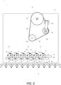
- FIG. 1 is a plan view schematically illustrating a conveying device 2 for an egg E including an egg transfer device 1 according to the present invention.
- the conveying device 2 for an egg includes a supply conveyor 3 having a plurality of rows in the Y direction with the X direction as a conveying direction for an egg, a distribution conveyor 4 that conveys eggs in a single row in the Y direction, and an egg transfer device 1 provided between the two conveyors.
- a packaging device (not illustrated) for packaging the conveyed eggs is connected to the downstream side of the distribution conveyor 4 in the conveying direction Y.
- the supply conveyor 3 is a multi-row conveyor that conveys, in the X direction, a plurality of eggs E in which long axes connecting sharp ends and blunt ends of the eggs E are arranged at a first pitch P1 along the Y direction.
- the supply conveyor 3 is exemplified as a multi-row conveyor including six rows that conveys six eggs E in such a manner that the long axes thereof are aligned in the same direction and at the first pitch P1.
- the first pitch P1 is 76.2 mm.
- a weighing device (not illustrated) is provided at the conveyance end portion of the supply conveyor 3.
- the weighing device measures the weight of the eggs E.
- An impeller 5 is provided above the weighing device. After weighing, the eggs E are pushed out from the supply conveyor 3 and moved to the egg transfer device 1 by the rotation of the impeller 5. The rotation speed of the impeller 5 is interlocked with the conveyance speed of the supply conveyor 3.
- the distribution conveyor 4 is a single-row conveyor that conveys, along the Y direction, the eggs E in which long axes of the eggs E are arranged along the Z direction (vertical direction).
- the distribution conveyor 4 is composed of an endless chain.
- Buckets 4a are provided in a single row at a second pitch P2 on the distribution conveyor 4 and are configured to open upward to receive the eggs E from above.
- the distribution conveyor 4 is configured to discharge for each size in the packaging device provided on the conveyance downstream side thereof.
- the second pitch P2 is 63.5 mm.
- the egg transfer device 1 is a device that is provided between the supply conveyor 3 and the distribution conveyor 4 and transfers a plurality of rows of eggs E supplied from the supply conveyor 3 to a single-row distribution conveyor 4.
- the egg transfer device 1 When transferring the plurality of eggs E to the distribution conveyor 4, the egg transfer device 1 is configured to transfer the eggs E to the buckets 4a of the distribution conveyor 4 at different transfer timings.
- the endless chain constituting the distribution conveyor 4 are not illustrated.
- the egg transfer device 1 includes a machine frame 6, acceleration trays 7, and drive systems 8 that each drive the acceleration tray 7.
- a plurality of the acceleration trays 7 are provided on the front side of the machine frame 6 in accordance with the number of rows provided in the supply conveyor 3.
- Each of the plurality of acceleration trays 7 is provided with an acceleration mechanism 9 that accelerates the acceleration tray 7.
- the acceleration mechanism 9 includes an acceleration tray drive shaft 10, a first crank arm 11, a bracket 13, a cam 14, and an egg pressing member 15.
- the acceleration tray drive shaft 10 is rotatably provided in the machine frame 6.
- One end of the first crank arm 11 is fixed to an end portion of the acceleration tray drive shaft 10.
- the plurality of first crank arms 11 are each fixed to the end portion of the acceleration tray drive shaft 10 at different angles.
- a first pivot shaft 12 is fixed to the other end of the first crank arm 11.
- a bracket 13 to which the acceleration tray 7 is attached is rotatably provided on the first pivot shaft 12, and a cam 14 is fixed to an end portion thereof.
- the plurality of first crank arms 11 are provided at different angles with respect to the acceleration tray drive shafts 10, when the first crank arms 11 rotate by the rotation of the acceleration tray drive shafts 10, the plurality of brackets 13 provided on the first pivot shafts 12 of the first crank arms 11 rotate at different phases.
- the plurality of first crank arms 11 are provided at different radii. Therefore, in the egg receiving states of the acceleration trays 7, the horizontal positions of the first pivot shafts 12 of the first crank arms 11 coincide with each other although the first crank arms 11 are provided at different angles with respect to the acceleration tray drive shafts 10.
- the bracket 13 is provided with the acceleration tray 7, a second pivot shaft 16, and a third pivot shaft 17.
- the acceleration tray 7 is provided on the bracket 13 so as to protrude toward the supply conveyor.
- the second pivot shaft 16 is provided on the bracket 13 so as to protrude toward the machine frame 6.
- a roller 18 is rotatably provided on the second pivot shaft 16.
- the roller 18 is fitted in a gap between an upper rail 19 and a lower rail 20 provided in the machine frame 6, and can reciprocate along the Y direction.
- the third pivot shaft 17 is provided on the bracket 13 so as to protrude toward the supply conveyor 3.
- the egg pressing member 15 is rotatably supported by the third pivot shaft 17 in a rotatable manner.
- the egg pressing member 15 includes a cam follower 21 and an egg pressing blade 22.
- a biasing means (not illustrated) is provided between the bracket 13 and the egg pressing member 15 so that the cam follower 21 comes into contact with the cam 14.
- the biasing means is configured by, for example, a tension spring.
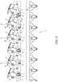
- FIGS. 3 and 4 are views illustrating postures of the acceleration trays 7.
- FIG. 3 illustrates an egg receiving state
- FIG. 4 illustrates an egg releasing state. The operation of the acceleration tray 7 will be described below.
- the roller 18 of the second pivot shaft 16 reciprocates in the horizontal direction (Y direction) at a position above the acceleration tray drive shaft 10.
- the acceleration tray drive shaft 10 rotates in the arrow direction
- the first crank arm 11 rotates
- the bracket 13 pivotally supported by the first pivot shaft 12 fixed to the first crank arm 11 swings about the second pivot shaft 16.
- a placement surface 23 of the acceleration tray 7 fixed to the bracket 13 changes its position from an egg receiving state position above the acceleration tray drive shaft 10 to a lower egg releasing state position.
- the acceleration tray 7 in the egg receiving state, is in a standby state substantially above the acceleration tray drive shaft 10 with the placement surface 23 for receiving the egg E facing upward.
- the egg pressing blade 22 of the egg pressing member 15 is held in an egg receiving state above the acceleration tray 7 by the cam 14. In this state, the egg E is transferred onto the placement surface 23 of the acceleration tray 7.
- the bracket 13 pivotally supported by the first pivot shaft 12 of the first crank arm 11 moves along with the horizontal movement of the second pivot shaft 16 to change the posture of the acceleration tray 7.
- the egg pressing blade 22 presses the egg E against the placement surface 23 of the acceleration tray 7 by a biasing means.
- the acceleration tray drive shaft 10 when the acceleration tray drive shaft 10 further rotates, the acceleration tray 7 is rotated so that the long axis of the egg E faces the Z-axis direction. Then, the acceleration tray 7 is accelerated in the Y direction to release the egg to the distribution conveyor 4. At this time, the egg pressing blade 22 releases the pressing of the egg E against the biasing means by the cam 14, and the egg E is released to the bucket 4a of the distribution conveyor 4 below the acceleration tray 7. After the egg E is released, the placement surface 23 of the acceleration tray 7 returns from the state illustrated in FIG. 4 to the state illustrated in FIG. 3 by the rotation of the acceleration tray drive shaft 10. By repeating the above, the egg transfer operation can be continued.
- the drive systems 8 are provided on the front side and the back side of the machine frame 6, and each drive the acceleration mechanism 9.
- a main drive shaft 24 and a sub-drive shaft 25 are rotatably provided on the front side of the machine frame 6.
- the main drive shaft 24 is driven in synchronization with the conveyance speed of the distribution conveyor 4.
- the main drive shaft 24 is provided with a main sprocket 26, and the sub-drive shaft 25 is provided with a sub-sprocket 27.
- the machine frame 6 is provided with a front-side tension sprocket 29 at an end portion of a swingable front-side swing arm 28.
- the front-side swing arm 28 is provided with a biasing means (not illustrated) that absorbs looseness of the main chain 30.
- the main chain 30 is looped between the main sprocket 26, the sub-sprocket 27, and the front-side tension sprocket 29. Therefore, when the main drive shaft 24 is driven, the sub-drive shaft 25 is driven by the main chain 30.
- the other end of the sub-drive shaft 25 protrudes toward the back side of the machine frame 6.
- the sub-drive shaft 25 and the acceleration tray drive shaft 10 are rotatably provided on the back side of the machine frame 6.
- a second crank arm 31 is fixed to the end portion of the sub-drive shaft 25 protruding from the front side to the back side of the machine frame 6.
- the second crank arm 31 is provided with a dual sprocket 32.
- the dual sprocket 32 functions as an eccentric sprocket.
- An acceleration tray sprocket 33 is fixed to one end of the acceleration tray drive shaft 10.
- the dual sprocket 32 of the second crank arm 31 fixed to the sub-drive shaft 25, a back-side swing arm 34, and a plurality of acceleration tray sprockets 33 fixed to the plurality of acceleration tray drive shafts 10 are provided.
- a sub-chain 36 is looped between the dual sprocket 32 and the plurality of acceleration tray sprockets 33.
- the sub-chain 36 is also looped around a plurality of idling sprockets 37 provided in the machine frame 6. Further, the sub-chain 36 is also looped around a back-side tension sprocket 35 provided at an end portion of the swingable back-side swing arm 34, and looseness of the sub-chain 36 is absorbed.
- the dual sprocket 32 functions as an eccentric sprocket
- the sub-chain 36 looped around the dual sprocket 32 is pulled, and the traveling speed thereof is accelerated when the sub-chain 36 moves away from the axial center of the sub-drive shaft 25 and is decelerated when the sub-chain 36 moves closer.
- the rotation speed of the acceleration tray sprocket 33 driven by the sub-chain 36 repeats acceleration and deceleration.
- the operation timings of the plurality of acceleration trays 7 can be individually shifted.
- This timing shift is achieved by providing a phase difference in the angle of each of the first crank arms 11 as illustrated in FIG. 3 .
- timings of the operations of the plurality of egg pressing members 15 can be individually shifted.
- This timing shift is caused by the timing at which the egg pressing member 15 is in the open state and the time during which the open state is maintained being individually set for each of the egg pressing members 15. These setting differences are achieved by making the shapes of the cams 14 different from each other.
- each of the acceleration trays 7 can have the same horizontal position in the egg receiving state although the phase difference is provided in the angles of the first crank arms 11. This is achieved by setting the radius of each of the first crank arms 11 to be different from each other in correlation with the angle of the first crank arm 11.
- FIGS. 6(a) and 6(b) are diagrams illustrating release timings of the eggs E in the first to sixth acceleration trays over time.
- the first to sixth acceleration trays release the eggs E at different timings in the order from the sixth acceleration tray at the right end to the first acceleration tray.
- the eggs E in the first to sixth acceleration trays are released at different timings in order from the right side in FIG. 6(b) , and are continuously transferred to the buckets 4a.
- the plurality of eggs E at the first pitch P1 on the supply conveyor 3 are accurately stored in the buckets 4a at the second pitch P2 on the distribution conveyor 4 in a continuous state by the egg transfer device 1.
- the speed of the distribution conveyor 4 can be suppressed to a low speed.
- the speed of the entire conveying device 2 is increased, it is possible to prevent an increase in the impact applied to the eggs when the eggs E are transferred from the supply conveyor 3 to the distribution conveyor 4, and it is possible to improve the processing capacity of the conveying device 2.
- the embodiment disclosed herein is an example and is not limited thereto.
- the plurality of rows of supply conveyors is not limited to six rows.
- the driving of the acceleration tray drive shaft 10 is not limited to the chain driving, and may be performed by, for example, a driving unit described in Japanese Patent Application Laid-Open No. 2011-173714 and illustrated in FIG. 7 .
- FIGS. 8 to 18 members corresponding to the first embodiment may be denoted by different reference numerals, and members different from the first embodiment may be denoted by the same reference numerals.
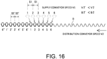
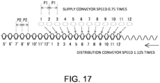
- the conveyance speed V2' of the distribution conveyor is reduced (V2' ⁇ V2) by narrowing the pitch of the buckets B of the distribution conveyor, and the eggs E are smoothly transferred from the transfer device to the distribution conveyor.
- the conventional supply conveyor generally conveys six rows of eggs, and can process 40,000 eggs per hour.
- 12 eggs are divided into four groups each including three eggs, and for each group, an attempt is made to reduce the pitch between the eggs by reducing the change in the release angle using the conventional technique.
- all the groups are operated "simultaneously" in the same manner as in the conventional technique, there is a new problem that a space is generated in the buckets of the distribution conveyor for each group and the conveyance efficiency of the distribution conveyor is lowered.
- An object of the present invention is to provide a transfer device capable of solving the problems of the conventional technique.
- a plurality of acceleration trays that each convert the long axis of the egg from the Y direction to the Z direction, accelerate the egg in the Y direction, and release the egg to the distribution conveyor are provided, and that the timing is an egg release timing of the acceleration tray.
- a plurality of relay receiving trays that each receive an egg from the supply conveyor and release the egg to the acceleration tray are provided, and the timing is synchronized with an egg release timing of the relay receiving tray.
- the plurality of relay trays and the plurality of acceleration trays are grouped, and the timings are shifted between the groups.
- the number of the plurality of trays is 12, and the groups are preferably first to fourth groups divided to each include three trays.
- the X, Y, and Z directions refer to orthogonal coordinates illustrated in FIGS. 8 and 9 .
- the eggs are transferred to the distribution conveyor at different transfer timings. Therefore, as compared with the conventional technique in which the eggs are simultaneously transferred, it is possible to prevent a space from being generated in the distribution conveyor, and it is possible to prevent a decrease in the conveyance efficiency of the distribution conveyor as compared with the conventional technique.
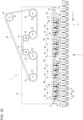
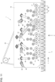
- FIG. 8 illustrates a conveying device 2 for an egg E including an egg transfer device 1 of the present invention.
- the conveying device 2 for an egg includes a multi-row supply conveyor 3, a single-row distribution conveyor 4, and an egg transfer device 1 provided between the conveyors 3 and 4.
- a packaging device for an egg (not illustrated) is connected to the downstream side in the conveying direction Y of the distribution conveyor 4.
- the supply conveyor 3 is a multi-row conveyor that conveys, in the X direction, a plurality of eggs E in which long axes connecting sharp ends and blunt ends of the eggs E are arranged at a first pitch P1 along the Y direction.
- the distribution conveyor 4 is a single-row conveyor including buckets 4a in which long axes of the eggs E are arranged along the Z direction (see FIG. 9 ) and the eggs E are conveyed in the Y direction at a second pitch P2 (see FIG. 14 ) along the Y direction.
- the bucket 4a is configured to open upward to receive the egg E from above, is provided at an end portion of a balance arm 4b so as to absorb the impact when receiving, and also moves in the vertical direction.
- the distribution conveyor 4 is connected to a conveyor that holds the eggs E of the buckets 4a from above and conveys them in a single row on the conveyance downstream side thereof, and is configured to be discharged for each size in the packaging device.
- the egg transfer device 1 transfers the plurality of eggs E from the supply conveyor 3 to the single-row distribution conveyor 4.
- the transfer device 1 is configured to transfer the eggs E to the buckets 4a of the distribution conveyor 4 by shifting the transfer timings, and the operation (action) thereof will be described later.
- the supply conveyor 3 is exemplified as a multi-row conveyor including 12 rows that conveys 12 eggs E at the first pitch P1 in an aligned manner such that the long axes thereof face the same direction.
- the first pitch P1 is 76.2 mm.
- Weighing devices 5 are provided at the conveyance end portion of the supply conveyor 3. 12 eggs E conveyed by the supply conveyor 3 are simultaneously received by trays 6 of the weighing devices 5 at the conveyance end.
- the weighing device 5 measures the weight of the egg E on the tray 6.
- An impeller 7 is provided above the tray 6 of the weighing device 5. After weighing, the egg E on the tray 6 is pushed out by the rotation of the impeller 7 and moved to the egg transfer device 1. The rotation speed of the impeller 7 is interlocked with the conveyance speed of the supply conveyor 3.
- the egg transfer device 1 includes relay trays 8.
- the relay receiving tray 8 receives the egg E pushed out by the impeller 7, and tilts to transfer the egg E to an acceleration tray 9.
- a guide 10 is provided between the relay tray 8 and the tray 6 of the weighing device 5. The egg E rolls on the guide 10 and is placed on the relay tray 8 with the long axis maintained in a posture along the Y-axis direction.
- the 12 relay receiving trays 8 are provided at the first pitch P1 of 76.2 mm on rotation shafts 11 along the Y-axis direction.
- the 12 relay receiving trays 8 are divided into four groups of first to fourth groups each including three trays.
- the rotation shafts 11 of the respective groups are provided to be independently rotatable.
- a rod 12 is vertically provided at an eccentric position of each of the rotation shafts 11.
- One end of a crank arm 13 is pivotally supported by the lower end of the rod 12.
- a cam follower 14 is provided at the other end of the crank arm 13. Since the intermediate point of the crank arm 13 is pivotally supported in a rotatable manner, the rod 12 is vertically movable.
- the cam follower 14 is engaged with a cam groove of a cam 15 that continuously rotates in one direction.
- the cam groove is formed in an annular shape having a convex portion in a part of the circumference.
- the rotation speed of the cam 15 is synchronized with the rotation of the impeller 7.
- the cam groove shapes of the four cams of the four groups of the first to fourth groups are the same, but a phase difference of 30 degrees is provided between the groups so that the positions of the protrusions are different. Due to this phase difference, the timings of the release of the eggs E are shifted between the groups. That is, the first to fourth groups sequentially release three eggs E to the acceleration trays 9 with a time difference.
- the egg transfer device 1 includes a machine frame 16.
- the machine frame 16 is provided with the acceleration trays 9.
- the acceleration trays 9 are provided on acceleration tray drive shafts 17 rotatably provided on the machine frame 16.
- 12 acceleration tray drive shafts 17 are provided, three acceleration tray drive shafts 17 are arranged at intervals of a pitch P3 to be divided into first to fourth groups, and the groups are arranged at intervals of a pitch P4 on the same line in the Y-axis direction.
- This grouping is the same as the grouping of the relay receivers 8.
- the pitch of the buckets 4a of the distribution conveyor 4 is P2.
- P2 57.15 mm
- P3 66.675 mm
- P4 95.25 mm.
- the acceleration tray drive shaft 17 is provided with an acceleration mechanism 18 for the acceleration tray 9.
- the acceleration mechanism 18 includes a crank arm 19 fixed to an end portion of the drive shaft 17.
- a first pivot shaft 20 is fixed to the other end of the crank arm 19.
- An acceleration tray mounting bracket 21 is rotatably provided on the first pivot shaft 20.
- the acceleration tray 9 is fixed to the bracket 21 so as to protrude toward the supply conveyor.
- the bracket 21 is provided with a second pivot shaft 22 so as to protrude toward the machine frame 16.
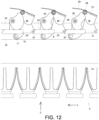
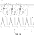
- a roller 23 is rotatably provided on the second pivot shaft 22 (see FIGS. 12 and 13 ).
- the roller 23 is fitted in a gap between the upper rail 24 and the lower rail 25 provided in the machine frame 16, and can reciprocate along the Y direction.
- the bracket 21 is provided with a third pivot shaft 26 so as to protrude toward the supply conveyor 3.
- An egg pressing member 27 is rotatably supported by the third pivot shaft 26 in a rotatable manner.
- the pressing member 27 is provided with a cam follower 28 and an egg pressing blade 29 (see FIGS. 12 and 13 ).
- a cam 30 is fixed to the first pivot shaft 20.
- a biasing means is provided between the bracket 21 and the pressing member 27 so that the cam follower 28 comes into contact with the cam 30.
- the biasing means is formed of a tension spring (not illustrated).
- the bracket 21 is provided with the first to third pivot shafts 20,22, and 26 and the acceleration tray 9.
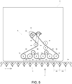
- FIGS. 12 and 13 are views illustrating postures of the acceleration trays 9 in the same group.
- FIG. 12 illustrates an egg receiving state
- FIG. 13 illustrates an egg releasing state.
- the roller 23 of the second pivot shaft 22 reciprocates in the horizontal direction (Y direction) at a position above the acceleration tray drive shaft 17.
- the bracket 21 pivotally supported by the first pivot shaft 20 of the crank arm 19 swings about the second pivot shaft 22. Due to the swing of the bracket 21, a placement surface 32 of the acceleration tray 9 provided in the bracket 21 changes its position from the upper side to the lower side of the drive shaft 17.
- FIG. 12 is a front view illustrating egg receiving postures of the acceleration trays in the group, and the acceleration trays 9 are each in a standby state substantially above the drive shaft 17 with a placement surface 32 for receiving the egg E facing upward.
- the egg pressing blade 29 of the holding member 27 is held at the upper open position by the cam 30. In this state, the egg from the relay tray 8 is transferred onto the placement surface 32 of the acceleration tray 9.
- the bracket 21 pivotally supported by the first pivot shaft 20 of the crank arm 19 moves along with the horizontal movement of the second pivot shaft 22, and changes the posture of the acceleration tray 9.
- the cam follower 28 of the pressing member 27 is not in contact with the cam 30, the egg pressing blade 29 presses the egg E against the placement surface 32 of the acceleration tray 9 by the biasing means.
- the posture of the acceleration tray 9 is set such that the long axis of the egg E faces the Z-axis direction. Then, the acceleration tray 9 is accelerated in the Y direction to release the egg into the bucket 4a of the distribution conveyor 4. At this time, the egg pressing blade 29 releases the pressing of the egg E against the biasing means by the cam 30, and the egg E is released to the bucket 4a of the distribution conveyor 4 below the acceleration tray 9. After releasing the egg E, the placement surface 32 of the acceleration tray 9 returns from the state illustrated in FIG. 13 to the state illustrated in FIG. 12 by the rotation of the drive shaft 17.
- the group drive shaft 33 is driven by power from a main drive shaft 34.
- the main drive shaft 34 is driven in synchronization with the conveyance speed of the distribution conveyor 4.
- the main drive shaft 34 is provided with a main sprocket 35, and the group drive shaft 33 is provided with a group sprocket 36.
- the machine frame 16 is provided with an idling sprocket 37.
- a main chain 38 is looped around the sprockets 35,36, and 37.
- crank arm 39 is fixed to the other end protruding from the machine frame 16.
- a dual sprocket 40 is fixed to the crank arm 39.
- the two sprockets 40 function as eccentric sprockets.
- An acceleration tray sprocket 41 is provided at an end portion of the acceleration tray drive shaft 17.
- a group chain 42 is looped between the dual sprocket 40 of the crank arm 39 and the acceleration tray sprocket 41.
- the group chain 42 is also looped around a plurality of idling sprockets 46 provided in the machine frame 16.
- the group chain 42 is looped around a tension sprocket 44 provided at an end portion of the swingable arm 43 to absorb looseness of the group chain 42.
- the swing arm 43 is provided with a biasing means (not illustrated) that absorbs looseness of the group chain 42. Note that, in FIG. 11 , the group chain 42 is illustrated as a reference for winding around only the third group from the left, but the group chain 42 is actually looped around all the first to fourth groups.
- the crank arm 39 rotates, and the dual sprocket 40 also rotates about the drive shaft 33. Since the dual sprocket 40 functions as an eccentric sprocket, the group chain 42 looped around the dual sprocket 40 is pulled and the traveling speed thereof is accelerated when the group chain 42 moves away from the axial center of the drive shaft 33, and is decelerated when the group chain 42 moves closer.
- the rotation speed of the acceleration tray sprocket 41 driven by the group chain 42 repeats acceleration and deceleration.
- the group drive shaft 33 and the group sprocket 36 illustrated in FIG. 10 are provided in a positionally adjustable manner.
- the movement timings of the grouped acceleration trays 9 can be shifted.
- this timing shift is achieved by phase differences in which the angles of the crank arms 39 are set to 30 degrees, 60 degrees, 90 degrees, and 120 degrees from the right end.
- the acceleration mechanisms 18 according to the first to fourth groups in FIG. 10 illustrate a state before the phase difference is provided.
- FIG. 5(a) illustrates the release of the three eggs E in the first group, and after the release, the release of the three eggs E in the second group is performed at different timings as illustrated in FIG. 5(b), so that the eggs E in the first group and the second group are continuously transferred to the buckets 4a of the distribution conveyors 4.
- the eggs E in the third group are released at different timings
- the eggs E in the fourth group are released at different timings, so that 12 eggs E are successively transferred to the distribution conveyor 4.
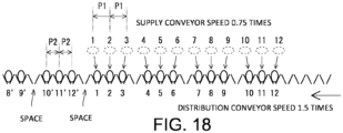
- the 12 eggs E at the first pitch P1 on the supply conveyor 3 are continuously stored in the buckets 4a at the second pitch P2 on the distribution conveyor 4 by the egg transfer device 1, and a decrease in the conveying efficiency of the distribution conveyor can be prevented as compared with the case where the conventional technique illustrated in FIG. 18 is applied.
- the embodiment disclosed herein is an example and is not limited thereto.
- the plurality of rows in the supply conveyor is not limited to 12 rows.
- the grouping is not limited to four groups. The same effect is achieved by shifting the discharge timings of the acceleration trays without further grouping.
- the driving of the acceleration tray drive shaft 17 is not limited to the chain driving, and may be performed by, for example, a driving unit described in Japanese Patent Application Laid-Open No. 2011-173714 and illustrated in FIG. 7 .
- the present invention can be used for conveying an egg.
Landscapes
- Engineering & Computer Science (AREA)
- Mechanical Engineering (AREA)
- Wrapping Of Specific Fragile Articles (AREA)
- Relays Between Conveyors (AREA)
Applications Claiming Priority (3)
| Application Number | Priority Date | Filing Date | Title |
|---|---|---|---|
| JP2022071223 | 2022-04-25 | ||
| JP2022123023 | 2022-08-01 | ||
| PCT/JP2023/012675 WO2023210246A1 (ja) | 2022-04-25 | 2023-03-28 | 卵移し替え装置 |
Publications (2)
| Publication Number | Publication Date |
|---|---|
| EP4516704A1 true EP4516704A1 (de) | 2025-03-05 |
| EP4516704A4 EP4516704A4 (de) | 2026-04-29 |
Family
ID=88518616
Family Applications (1)
| Application Number | Title | Priority Date | Filing Date |
|---|---|---|---|
| EP23795993.7A Pending EP4516704A4 (de) | 2022-04-25 | 2023-03-28 | Eiertransfervorrichtung |
Country Status (5)
| Country | Link |
|---|---|
| EP (1) | EP4516704A4 (de) |
| JP (1) | JPWO2023210246A1 (de) |
| KR (1) | KR20250004255A (de) |
| CN (1) | CN119053532A (de) |
| WO (1) | WO2023210246A1 (de) |
Family Cites Families (5)
| Publication number | Priority date | Publication date | Assignee | Title |
|---|---|---|---|---|
| US3894631A (en) * | 1973-12-26 | 1975-07-15 | Fmc Corp | Egg transfer mechanism |
| JPS538423A (en) | 1976-07-10 | 1978-01-25 | Ntn Toyo Bearing Co Ltd | Flow rate measuring means |
| JPH0912135A (ja) | 1995-06-28 | 1997-01-14 | Kyowa Kikai Kk | 鶏卵の移し替え装置 |
| JP5063241B2 (ja) * | 2006-12-29 | 2012-10-31 | 株式会社ナベル | 卵の移載装置 |
| JP2011173714A (ja) | 2010-02-25 | 2011-09-08 | Kyowa Machinery Co Ltd | 卵移し替え装置及びこれに用いられる移し替え用卵座 |
-
2023
- 2023-03-28 CN CN202380035525.6A patent/CN119053532A/zh active Pending
- 2023-03-28 EP EP23795993.7A patent/EP4516704A4/de active Pending
- 2023-03-28 WO PCT/JP2023/012675 patent/WO2023210246A1/ja not_active Ceased
- 2023-03-28 JP JP2024517917A patent/JPWO2023210246A1/ja active Pending
- 2023-03-28 KR KR1020247037029A patent/KR20250004255A/ko active Pending
Also Published As
| Publication number | Publication date |
|---|---|
| KR20250004255A (ko) | 2025-01-07 |
| WO2023210246A1 (ja) | 2023-11-02 |
| EP4516704A4 (de) | 2026-04-29 |
| CN119053532A (zh) | 2024-11-29 |
| JPWO2023210246A1 (de) | 2023-11-02 |
Similar Documents
| Publication | Publication Date | Title |
|---|---|---|
| EP0124177B1 (de) | Vorrichtung für den Transfer einer Reihe von Gegenständen von einem Bandförderer zu einem transversal laufenden Bandförderer | |
| EP2842877B1 (de) | Eibeförderungsvorrichtung und Verfahren zur Übertragung von Eiern | |
| CN102361808B (zh) | 用于借助夹持器将产品从输入输送带转送到排出输送带上的装置及用于运行该装置的方法 | |
| JP5063241B2 (ja) | 卵の移載装置 | |
| EP2838819B1 (de) | Fördersystem und verfahren zur erzeugung einer sequenz diskreter lebensmittelartikel aus einer mehrzahl von eingehenden lebensmittelobjekten | |
| US4679685A (en) | Accumulating commodity conveyor | |
| EP0695703A1 (de) | Einrichtung zum gruppenweisen Fördern von Produkten | |
| WO2016122897A1 (en) | Flipping apparatus, system and method for processing articles | |
| EP4516704A1 (de) | Eiertransfervorrichtung | |
| US10099865B2 (en) | Method and device for conveying piece products | |
| US4669600A (en) | Apparatus for forming groups of edgewise upright oriented articles and method of operating the apparatus | |
| EP2560882B1 (de) | Vorrichtung und verfahren zum zuführen von eiern zu einer verpackungseinheit | |
| JP2008247511A (ja) | スライス食パン分割搬出装置 | |
| US2815848A (en) | Package metering and stacking mechanism | |
| US4033447A (en) | Container line divider | |
| US3207286A (en) | Vial loading apparatus | |
| US5158277A (en) | Method and apparatus for conveying printed products | |
| JPH05319565A (ja) | 物品のグルーピング装置 | |
| EP3581504B1 (de) | Eiverarbeitungsvorrichtung | |
| JP3764928B2 (ja) | バッファコンベア | |
| US4925006A (en) | Conveyor apparatus having means for a shock-free article acceleration | |
| JPH0912135A (ja) | 鶏卵の移し替え装置 | |
| JPH0692436A (ja) | びん整列装置 | |
| US9073702B2 (en) | Feeding device | |
| JP3208707B2 (ja) | 鶏卵の移替え装置 |
Legal Events
| Date | Code | Title | Description |
|---|---|---|---|
| STAA | Information on the status of an ep patent application or granted ep patent |
Free format text: STATUS: THE INTERNATIONAL PUBLICATION HAS BEEN MADE |
|
| PUAI | Public reference made under article 153(3) epc to a published international application that has entered the european phase |
Free format text: ORIGINAL CODE: 0009012 |
|
| STAA | Information on the status of an ep patent application or granted ep patent |
Free format text: STATUS: REQUEST FOR EXAMINATION WAS MADE |
|
| 17P | Request for examination filed |
Effective date: 20241108 |
|
| AK | Designated contracting states |
Kind code of ref document: A1 Designated state(s): AL AT BE BG CH CY CZ DE DK EE ES FI FR GB GR HR HU IE IS IT LI LT LU LV MC ME MK MT NL NO PL PT RO RS SE SI SK SM TR |
|
| DAV | Request for validation of the european patent (deleted) | ||
| DAX | Request for extension of the european patent (deleted) |