EP4516673A1 - Toilette mit wiederverwendung von grauwasser zum toilettenspülen - Google Patents
Toilette mit wiederverwendung von grauwasser zum toilettenspülen Download PDFInfo
- Publication number
- EP4516673A1 EP4516673A1 EP23194594.0A EP23194594A EP4516673A1 EP 4516673 A1 EP4516673 A1 EP 4516673A1 EP 23194594 A EP23194594 A EP 23194594A EP 4516673 A1 EP4516673 A1 EP 4516673A1
- Authority
- EP
- European Patent Office
- Prior art keywords
- greywater
- supply pipe
- discharge
- flushing supply
- lavatory
- Prior art date
- Legal status (The legal status is an assumption and is not a legal conclusion. Google has not performed a legal analysis and makes no representation as to the accuracy of the status listed.)
- Pending
Links
Images

Classifications
-
- E—FIXED CONSTRUCTIONS
- E03—WATER SUPPLY; SEWERAGE
- E03D—WATER-CLOSETS OR URINALS WITH FLUSHING DEVICES; FLUSHING VALVES THEREFOR
- E03D11/00—Other component parts of water-closets, e.g. noise-reducing means in the flushing system, flushing pipes mounted in the bowl, seals for the bowl outlet, devices preventing overflow of the bowl contents; devices forming a water seal in the bowl after flushing, devices eliminating obstructions in the bowl outlet or preventing backflow of water and excrements from the waterpipe
- E03D11/13—Parts or details of bowls; Special adaptations of pipe joints or couplings for use with bowls, e.g. provisions in bowl construction preventing backflow of waste-water from the bowl in the flushing pipe or cistern, provisions for a secondary flushing, for noise-reducing
- E03D11/17—Means for connecting the bowl to the flushing pipe
-
- B—PERFORMING OPERATIONS; TRANSPORTING
- B64—AIRCRAFT; AVIATION; COSMONAUTICS
- B64D—EQUIPMENT FOR FITTING IN OR TO AIRCRAFT; FLIGHT SUITS; PARACHUTES; ARRANGEMENT OR MOUNTING OF POWER PLANTS OR PROPULSION TRANSMISSIONS IN AIRCRAFT
- B64D11/00—Passenger or crew accommodation; Flight-deck installations not otherwise provided for
- B64D11/02—Toilet fittings
-
- E—FIXED CONSTRUCTIONS
- E03—WATER SUPPLY; SEWERAGE
- E03F—SEWERS; CESSPOOLS
- E03F1/00—Methods, systems, or installations for draining-off sewage or storm water
- E03F1/006—Pneumatic sewage disposal systems; accessories specially adapted therefore
-
- E—FIXED CONSTRUCTIONS
- E03—WATER SUPPLY; SEWERAGE
- E03D—WATER-CLOSETS OR URINALS WITH FLUSHING DEVICES; FLUSHING VALVES THEREFOR
- E03D2201/00—Details and methods of use for water closets and urinals not otherwise provided for
- E03D2201/40—Devices for distribution of flush water inside the bowl
Definitions
- the present disclosure generally relates to a greywater reuse lavatory for a vehicle and a corresponding vehicle equipped therewith.
- the present disclosure relates to a greywater reuse lavatory buffering greywater from a water consumer and flushing a toilet bowl with the greywater via a flushing supply pipe having a plurality of nozzles, wherein the flushing supply pipe can be flushed via a discharge.
- greywater means waste water without contamination that would harm human beings.
- Sources of greywater include a sink, water fountain, shower, dishwasher, or the like, but excludes wastewater from toilets (sometimes referred to as blackwater).
- a conventional lavatory such as a lavatory installed in an aircraft or other passenger vehicle, provides fresh water to a water consumer, such as a faucet and sink, as well as to a toilet bowl for flushing the toilet.
- a water consumer such as a faucet and sink
- a toilet bowl for flushing the toilet.
- This facilitates piping, as the water consumer and the toilet bowl can be connected to the same freshwater delivery system.
- employing fresh water to flush the toilet requires additional equipment, such as a backflow prevention for hygienic reasons, e.g., a vacuum breaker.
- some vehicles are equipped with a greywater collecting tank, into which all water consumers producing only greywater can drain. This greywater is then used to supply a plurality of toilet flushing systems in the vehicle.
- greywater can include some particles, fibres, organic matter, or the like.
- a physical/chemical treatment, including a filter has to be installed with such greywater distribution systems.
- toilet flushing systems usually include nozzles having a small outlet cross-section, which may clog from the particles, fibres, organic matter, etc. in the greywater.
- filter cleaning e.g. chemical treatment
- greywater treatment e.g. chemical treatment
- a greywater reuse lavatory for an aircraft comprises a water consumer associated with a (fresh) water source, and a greywater buffer fluidly coupled to a drain of the water consumer and configured to buffer a predefined amount of greywater drained from the water consumer.
- the greywater reuse lavatory further comprises a toilet bowl, a flushing supply pipe fluidly coupled to the greywater buffer and arranged in or at the toilet bowl, and a plurality of nozzles arranged in the flushing supply pipe and configured to flush the toilet bowl with greywater.
- the water consumer can be a sink, water fountain, shower, dishwasher, or the like.
- the associated water source can be connected to a freshwater supply system, so that the water consumer consumes (supplies) freshwater.
- the greywater conveying device can be operated under a predefined time regime.
- the greywater conveying device may be operated/activated when a user presses a corresponding button to flush the toilet bowl.
- the pressing of such a button may be used as an indication, but the actual operation of the conveying device and/or actual flushing of the toilet bowl is performed with the preset delay or based on other factors, for example, when a vacuum waste water system is ready to flush the toilet bowl.
- the greywater buffer portion of the piping
- the greywater buffer tank is to be installed upstream of the greywater conveying device.
- the greywater conveying device can be provided in the greywater buffer (tank), such as at an end of portion of a piping configured to buffer the greywater or at an outlet of the greywater buffer tank.
- the drain of the water consumer may be configured to be closed, and a device may be provided that pressurises the greywater in the greywater buffer (tank), e.g., with pressurised air.
- the greywater conveying device can be configured to pressurises the greywater in the greywater (tank).
- the flushing supply pipe can be a continuous ring arranged in an upper area of the toilet bowl.
- the flushing supply pipe can be arranged in such a way that the nozzles spray greywater onto the inner surface of the toilet bowl, in order to support cleaning the inner surface and flush the toilet bowl
- the discharge can be arranged anywhere along this flushing supply pipe ring.
- the flushing supply pipe has an end downstream of the inlet of the flushing supply pipe, and the discharge is arranged at this end of the flushing supply pipe. This allows ensuring that the entire flushing supply pipe will be flushed out and avoids any dead ends or portions of the flushing supply pipe that will not be flushed out or cleaned, when the discharge is brought into an open position.
- the flushing supply pipe can have at least one branch and a further discharge, wherein the at least one branch is arranged continuously from the inlet of the flushing supply pipe to the further discharge along an inner circumference of the toilet bowl.
- the flushing supply pipe can have a Y-shape or horseshoe shape, wherein a discharge is arranged at each end, and the inlet is provided anywhere between these two ends. This allows flushing out or cleaning the flushing supply pipe more easily, as the sections to be flushed out or cleaned are shorter compared to a flushing supply pipe with only one end.
- the greywater reuse lavatory can further comprise a further discharge arranged between an inlet and any point of the flushing supply pipe downstream of the inlet. This allows providing the discharge and the further discharge at different positions along the flushing supply pipe, so that shorter sections of the flushing supply pipe can be flushed out or cleaned.
- only one discharge may be brought into an open position at a time.
- specific sections of the flushing supply pipe can be flushed out or cleaned.
- the discharge closest to the inlet can be opened first and thereafter any discharge downstream therefrom is (subsequently) opened.
- the greywater reuse lavatory can further comprise a plurality of discharges, particularly two or more discharges. This also applies to each branch of the flushing supply pipe that may likewise comprise a plurality of discharges.
- the discharge can comprise a mechanical valve configured to open, if a pressure of the greywater in the flushing supply pipe exceeds a predefined threshold.
- the predefined threshold (a predefined greywater pressure in the flushing supply pipe) can be set to be higher than a pressure used to flush the toilet bowl.
- the discharge can include a biasing element, such as a spring, biasing the discharge into the closed position.
- the discharge can further be arranged and configured, so that the pressurised greywater acts against the biasing element (e.g., via the valve element or flap).
- the biasing element By choosing or setting the biasing element in such a manner that it only withstands the predefined (threshold) pressure, any higher pressure will open the discharge and the greywater can be discharged through the discharge, thereby flushing out and cleaning the flushing supply pipe.
- the discharge can comprise an electrically and/or pneumatically controlled valve or flap.
- the flushing supply pipe can be flushed out or cleaned irrespective of the pressure under which the greywater is provided into the flushing supply pipe.
- a drain of the toilet bowl can be fluidly connected to a vacuum waste water system, and the pneumatically controlled valve or flap is driven by the vacuum present in the vacuum waste water system.
- the vacuum of the vacuum waste water system can be used to bring the pneumatically controlled discharge into the open position and/or the closed position.
- any piping required to pneumatically or control the valve or flap can be very short.
- the discharge may likewise be brought into the closed position by a mechanical biasing element, while the vacuum of the vacuum waste water system is used to open the discharge.
- the discharge can be fluidly connected to a vacuum waste water system.
- the discharge can be connected to the vacuum waste water system on a discharge side of the discharge.
- a fluid connection is achieved between the interior of the flushing supply pipe and the vacuum waste water system.
- the discharge does not open into the toilet bowl, but into the vacuum waste water system.
- Any greywater used to flush out or clean the flushing supply pipe is directly fed into the vacuum waste water system (instead of via the toilet bowl and associated drain). This further facilitates flushing out or cleaning the flushing supply pipe, as the pressure difference between the greywater buffer (or greywater conveying device) and the vacuum waste water system is greater than a pressure difference between the greywater and the ambient.
- At least some of the plurality of nozzles can be made of a rigid material.
- at least some of the plurality of nozzles can be made from a rigid plastic or metal. This allows providing a constant flushing behaviour of the toilet bowl, particularly if the greywater is pressurised with the same pressure.
- At least some of the plurality of nozzles can be made of an elastic material configured to expand based on a pressure of the greywater in the flushing supply pipe. Specifically, with increasing pressure of the greywater, the nozzles expand and their cross-sectional area increases. Thus, by increasing the pressure of the greywater, particularly above a predefined threshold (pressure level) being higher than a regular greywater pressure for flushing the toilet bowl, material accumulated at the nozzle can be flushed out and the nozzle can be cleaned. This allows an additional cleaning effect before or when the discharge is opened.
- a predefined threshold pressure level
- the greywater reuse lavatory can further comprise a control unit configured to control the greywater reuse lavatory, so that the discharge achieves an open state and the flushing supply pipe is flushed with greywater through the discharge.
- control unit can be coupled with the greywater conveying device, in order to convey greywater towards the flushing supply pipe. This further allows providing the greywater with a pressure opening the discharge, particularly a mechanically operated discharge, and further providing a sufficient flow rate of the greywater through the flushing supply pipe and discharge.
- control unit can be configured to control this means, in order to open and close the discharge, whenever necessary.
- control unit can also control a regular flush of the toilet only via the nozzles, for example, by operating the conveying device accordingly and/or closing the discharge(s).
- control unit can further be configured to fill the greywater buffer (tank) before a regular flush of the toilet bowl, in case the greywater buffer (tank) does not buffer enough water for one flush.
- control unit can be configured to control a valve filling the greywater buffer (tank) with freshwater.
- control unit can also be configured to control the water source of the water consumer, such as a faucet of a sink or a water fountain, in order to fill the greywater buffer (tank).
- control unit can further be configured to flush out or clean the flushing supply pipe at regular intervals, such as after a specific number of flushes or after a specific time period. In this case, the control unit can count the number of flushes or measure the time since the last time the flushing supply pipe was flushed out or cleaned.
- the greywater buffer can buffer greywater from more than one water consumer.
- This plurality of water consumers can be of the same monument as well as of different monuments, wherein a monument can be a lavatory, a galley, a shower, a water fountain or the like.
- an aircraft comprises at least one greywater reuse lavatory of the first aspect or one or more of its variants.
- each greywater reuse lavatory comprises its own greywater buffer (tank)
- such buffer (tank) can be sized much smaller compared to a corresponding tank in a general greywater collection system.
- the greywater buffer (tank) can be sized to buffer greywater for a small number of toilet flushes, such as a one flush, two flushes or three flushes. This buffer size is usually sufficient, as a sink is used by passengers at least as often as the toilet bowl is flushed, so that sufficient grey water can be buffered.
- the freshwater supply system of the aircraft can be operated with a decreased pressure, since the highest pressure is usually required for flushing the toilet.
- smaller freshwater pipes and pumps can be installed in the aircraft.
- FIG. 1 schematically illustrates a greywater reuse lavatory 10 comprising a water consumer 110 associated with a water source 112, which are depicted exemplarily as a sink and a schematic faucet.
- the water consumer 110 has a drain 113, through which used water, referred to as a greywater, is drained.
- this greywater is water containing soap or the like used by a passenger washing their hands or the like.
- the greywater reuse lavatory 10 further comprises a greywater buffer, which is illustrated as a greywater buffer tank 120 fluidly coupled to the drain 113 of the water consumer 110 and configured to buffer a predefined amount of greywater drained from the water consumer 110.
- a greywater buffer tank 120 fluidly coupled to the drain 113 of the water consumer 110 and configured to buffer a predefined amount of greywater drained from the water consumer 110.
- the greywater pipe 125 fluidly connected to the drain 113 and/or the greywater pipe 135 can also be configured to act as a greywater buffer.
- the greywater pipe 125, 135 may be sized (an inner diameter) over a predefined portion (length) to buffer greywater drained from the water consumer 110.
- a specific greywater buffer tank 120 of predefined volume may be installed irrespective of the buffer capability of the greywater pipe 125, 135. Actually, any greywater pipe will have an inherent buffer volume.
- greywater buffer 125, 135) and “greywater buffer tank” (120) can be used interchangeably and the present disclosure is not restricted to the presence of a dedicated tank 120.
- greywater is used for a toilet flush, so that the predefined amount of greywater stored by the greywater pipe 125, 135 and/or the buffer tank 120 can correspond to one flush, two flushes or three flushes, while the present disclosure is not restricted to the number of flushes.
- the greywater buffer tank 120 is fluidly connected to greywater pipes 125, 135 arranged downstream of the buffer tank 120, in order to release greywater from the buffer tank 120 for further use.
- the greywater pipe 125 or the greywater buffer tank 120 may be fluidly connected to a waste water system, for example, via a connection 127. This allows releasing greywater from the buffer 120, 125 into the waste water system, for example, in case the buffer 120, 125 is filled (with the predefined amount of greywater and/or completely).
- the waste water system can be a vacuum waste water system.
- the connection 127 can be employed to connect the greywater pipe 125 to an overboard drain, where the greywater is directly released from the vehicle (aircraft).
- the greywater pipe 135 is fluidly connected to a toilet bowl 140 of the lavatory 10, in order to use the greywater as toilet flushing water.
- a flushing supply pipe 150 fluidly coupled to the greywater buffer 120, 125 via the greywater pipes 125, 135 (or directly to the greywater pipes 125, 135 having sufficient buffer volume).
- the flushing supply pipe 150 is arranged in or at the toilet bowl 140, in order to release greywater into the toilet bowl 140 to flush it. The details of the flushing supply pipe 150 will be explained with respect to Figures 2 and 3 .
- the toilet bowl 140 has a drain 145 which can be coupled to a waste water system, such as a vacuum waste water system of a vehicle, in which the lavatory 10 is installed. This is schematically illustrated as a connection 147.
- the lavatory 10 can further comprise a greywater conveying device 130 configured to convey greywater from the greywater buffer 120, 125 to the flushing supply line 150.
- a greywater conveying device 130 configured to convey greywater from the greywater buffer 120, 125 to the flushing supply line 150.
- This can include pressurising the greywater by the greywater conveying device 130.
- flushing the toilet bowl 140 usually requires a cleaning effect by the flushing water, which can be achieved by spraying the greywater under a particular pressure into the toilet bowl 140.
- the lavatory 10 can further comprise a control unit 200 configured to control the greywater reuse lavatory 10.
- the control unit 200 can control the conveying device 130, for example, for flushing the toilet as well as flushing out or cleaning the flushing supply pipe 150, as will now be explained in more detail with respect to Figures 2 and 3 .
- FIG 2 schematically illustrates details of an exemplary greywater flushing supply pipe 150.
- the flushing supply pipe 150 is arranged in or at the toilet bowl 140 (not depicted in Figure 2 for sake of brevity) and comprises a plurality of nozzles 155 arranged in the flushing supply pipe 150 and configured to flush the toilet bowl 140 with greywater.
- the nozzles 155 can be arranged at a bottom of the flushing supply pipe 150 and/or can be directed to spray onto an inner surface of the toilet bowl 140.
- the arrows depicted in Figure 2 illustrate a greywater flow from the greywater pipe 135 through the inlet 151 of the flushing supply pipe 150 and towards each nozzle 155.
- the conveying device 130 conveys greywater from the buffer 120, 125 into the flushing supply pipe 150
- the greywater is sprayed via the nozzles 155 into the toilet bowl 140.
- the number of depicted nozzles 155 does not limit the present disclosure. It is to be understood that any number of nozzles 155 can be arranged in the flushing supply pipe 150, depending on the cleaning effect that is to be achieved by the nozzles 155.
- FIG. 2 schematically illustrates the flushing supply pipe 150 as forming an incomplete ring. It is to be understood that the form of the flushing supply pipe (in the plan view of Figure 2 ) is not restricted to a circle or ring, but rather depends on the shape of the toilet bowl 140.
- Figure 2 further illustrates a cross-section of the flushing supply pipe 150 taken along the circumferential direction of the supply pipe 150, i.e. the flowing direction of the greywater through the supply pipe 150.
- the flushing supply pipe 150 further comprises a discharge 157 configured to selectively open and close.
- the discharge 157 is illustrated as being arranged at an end of the flushing supply pipe 150 downstream of the inlet 151, where the flushing supply pipe 150 is fluidly connected to the greywater pipe 135. This allows arranging the flushing supply pipe 150 continuously from the inlet 151 to the discharge 157 along an inner circumference of the toilet bowl 140.
- the discharge 157 is closed, i.e. is in a closed position.
- greywater can include material that may clog the nozzles 155, flushing out or cleaning the flushing supply pipe 150 should be performed regularly. This may be, for example, achieved under control of the control unit 200.
- the flushing out or cleaning of the flushing supply pipe 150 under a higher pressure may be facilitated by installing at least some nozzles 155 made of an elastic material.
- Such elastic material can be configured to expand based on a pressure of the greywater in the flushing supply pipe 150.
- the cross-sectional area of the respective nozzles 155 increases, so that accumulated or clogging material can already be flushed out through the nozzle 155. Any other material accumulated in the flushing supply pipe 150 can be flushed out through the discharge 157.
- the discharge 157 can alternatively or additionally comprise an electrically and/or pneumatically controlled valve or flap.
- Such valve or flap can be controlled by the control unit 200 directly, i.e., via electrical signals and/or pneumatic control means.
- the control unit 200 can open and close the discharge 157 any time, when it is desired to flush out or clean the flushing supply pipe 150.
- a pneumatically controlled valve or flap, or its actuator can be connected to the vacuum waste water system, so that the vacuum thereof, i.e. the low pressure or pressure difference to the ambient, can be used to operate the discharge 157.
- discharges 157 can be combined with a mechanically operated actuator. For instance, opening the discharge 157 may be achieved pneumatically and/or electrically, and closing the discharge 157 may be achieved mechanically, such as by a spring or biasing element.
- greywater reuse would include the installation of a plurality of flushing supply pipes 150, each having one or more branches and a corresponding number of discharges 157. This can be achieved by branching the grey water pipe 135 and providing grey water to each of the plurality of flushing supply pipes 150.
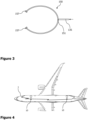
- FIG 4 schematically illustrates an aircraft 1 comprising a plurality of greywater reuse lavatories 10. It is to be understood that the number of greywater reuse lavatories 10 in the aircraft 1 is not restricted to the illustrated two lavatories 10. Actually, any water consuming monument, such as a lavatory, a galley, a shower, a water fountain or the like, required in the aircraft 1 can include the components of a greywater reuse lavatory 10 as explained with respect to Figures 1 to 3 .
- another monument having a water consumer, but no toilet bowl, can be installed next to or close to a greywater reuse lavatory 10. Drained water from this water consumer would be fed into the greywater buffer 120, 125 of the greywater reuse lavatory 10.
- a water fountain or a galley with a sink, coffeemaker, and/or dishwasher may be fluidly connected to the greywater buffer 120, 125. This allows filling the buffer 120, 125 faster and more efficiently.
Landscapes
- Engineering & Computer Science (AREA)
- Aviation & Aerospace Engineering (AREA)
- Health & Medical Sciences (AREA)
- Life Sciences & Earth Sciences (AREA)
- Hydrology & Water Resources (AREA)
- Public Health (AREA)
- Water Supply & Treatment (AREA)
- Sanitary Device For Flush Toilet (AREA)
Priority Applications (2)
| Application Number | Priority Date | Filing Date | Title |
|---|---|---|---|
| EP23194594.0A EP4516673A1 (de) | 2023-08-31 | 2023-08-31 | Toilette mit wiederverwendung von grauwasser zum toilettenspülen |
| US18/819,028 US20250075485A1 (en) | 2023-08-31 | 2024-08-29 | Lavatory reusing greywater for flushing a toilet |
Applications Claiming Priority (1)
| Application Number | Priority Date | Filing Date | Title |
|---|---|---|---|
| EP23194594.0A EP4516673A1 (de) | 2023-08-31 | 2023-08-31 | Toilette mit wiederverwendung von grauwasser zum toilettenspülen |
Publications (1)
| Publication Number | Publication Date |
|---|---|
| EP4516673A1 true EP4516673A1 (de) | 2025-03-05 |
Family
ID=87889307
Family Applications (1)
| Application Number | Title | Priority Date | Filing Date |
|---|---|---|---|
| EP23194594.0A Pending EP4516673A1 (de) | 2023-08-31 | 2023-08-31 | Toilette mit wiederverwendung von grauwasser zum toilettenspülen |
Country Status (2)
| Country | Link |
|---|---|
| US (1) | US20250075485A1 (de) |
| EP (1) | EP4516673A1 (de) |
Citations (3)
| Publication number | Priority date | Publication date | Assignee | Title |
|---|---|---|---|---|
| US4521925A (en) * | 1982-06-30 | 1985-06-11 | The Boeing Company | Nonrecirculating vacuum flush toilet system utilizing fresh water |
| EP0530859B1 (de) * | 1988-09-06 | 1996-12-27 | Metra Oy AB | Vakuumtoilettensystem |
| US5692250A (en) * | 1989-08-15 | 1997-12-02 | Oy Wartsila Ab | Vacuum toilet system with treated rinse liquid |
-
2023
- 2023-08-31 EP EP23194594.0A patent/EP4516673A1/de active Pending
-
2024
- 2024-08-29 US US18/819,028 patent/US20250075485A1/en active Pending
Patent Citations (3)
| Publication number | Priority date | Publication date | Assignee | Title |
|---|---|---|---|---|
| US4521925A (en) * | 1982-06-30 | 1985-06-11 | The Boeing Company | Nonrecirculating vacuum flush toilet system utilizing fresh water |
| EP0530859B1 (de) * | 1988-09-06 | 1996-12-27 | Metra Oy AB | Vakuumtoilettensystem |
| US5692250A (en) * | 1989-08-15 | 1997-12-02 | Oy Wartsila Ab | Vacuum toilet system with treated rinse liquid |
Also Published As
| Publication number | Publication date |
|---|---|
| US20250075485A1 (en) | 2025-03-06 |
Similar Documents
| Publication | Publication Date | Title |
|---|---|---|
| CA2789121C (en) | Flush water container system for flush water for a mobile toilet | |
| US8074933B2 (en) | Aircraft graywater ejection system | |
| EP2849998B1 (de) | Zweistufige spülungs- und grauwasserspülungssysteme und -vorrichtungen | |
| US10036153B2 (en) | Toilet device having a backflushing function for a particle filter | |
| EP0363012B1 (de) | Vakuumtoilettensystem | |
| US4521925A (en) | Nonrecirculating vacuum flush toilet system utilizing fresh water | |
| RU2452820C2 (ru) | Вакуумная канализационная система | |
| EP2951089B1 (de) | Toiletten mit verbesserter entfernbarkeit für fahrgasttransportfahrzeuge | |
| US11535527B2 (en) | Grey-water processing device for rail vehicles | |
| CN102627112A (zh) | 具有水箱旁路的水存储和分配系统 | |
| RU191868U1 (ru) | Устройство водоснабжения для рельсового транспортного средства | |
| EP2937480B1 (de) | Installation aufweisend einen druckspülkasten für toiletten | |
| EP4516673A1 (de) | Toilette mit wiederverwendung von grauwasser zum toilettenspülen | |
| US20140013498A1 (en) | Aircraft Lavatory Urinal | |
| EP4361041A1 (de) | Wasserversorgungssystem mit grauwasserwiederverwendung und flugzeug mit solch einem wasserversorgungssystem | |
| EP4331990B1 (de) | Wasserversorgungs- und verteilungssystem an bord eines flugzeugs und verfahren zum betrieb solch eines systems mit geringem wartungsaufwand | |
| EP4566948A1 (de) | Flugzeugtoilette mit hochdruckwasserspülung | |
| KR101782526B1 (ko) | 압축공기를 이용한 절수형 변기 | |
| RU2428338C1 (ru) | Вакуумная туалетная система транспортного средства | |
| EP4058354B1 (de) | Zweikanal-spülringsystem für eine toilette | |
| JP2002021147A (ja) | シャワー方式のアキュームレータを備えた水洗トイレ | |
| KR20190001273A (ko) | 절수형 양변기 | |
| JP2023140383A (ja) | 災害対応便器 | |
| WO2003074798A1 (en) | A toilet |
Legal Events
| Date | Code | Title | Description |
|---|---|---|---|
| PUAI | Public reference made under article 153(3) epc to a published international application that has entered the european phase |
Free format text: ORIGINAL CODE: 0009012 |
|
| STAA | Information on the status of an ep patent application or granted ep patent |
Free format text: STATUS: THE APPLICATION HAS BEEN PUBLISHED |
|
| AK | Designated contracting states |
Kind code of ref document: A1 Designated state(s): AL AT BE BG CH CY CZ DE DK EE ES FI FR GB GR HR HU IE IS IT LI LT LU LV MC ME MK MT NL NO PL PT RO RS SE SI SK SM TR |
|
| STAA | Information on the status of an ep patent application or granted ep patent |
Free format text: STATUS: REQUEST FOR EXAMINATION WAS MADE |
|
| 17P | Request for examination filed |
Effective date: 20250905 |