EP4516632A1 - Abdeckungsverbindungsstruktur und träger - Google Patents
Abdeckungsverbindungsstruktur und träger Download PDFInfo
- Publication number
- EP4516632A1 EP4516632A1 EP24198467.3A EP24198467A EP4516632A1 EP 4516632 A1 EP4516632 A1 EP 4516632A1 EP 24198467 A EP24198467 A EP 24198467A EP 4516632 A1 EP4516632 A1 EP 4516632A1
- Authority
- EP
- European Patent Office
- Prior art keywords
- engaging member
- groove
- limiting
- fixing base
- cover
- Prior art date
- Legal status (The legal status is an assumption and is not a legal conclusion. Google has not performed a legal analysis and makes no representation as to the accuracy of the status listed.)
- Pending
Links
Images




Classifications
-
- B—PERFORMING OPERATIONS; TRANSPORTING
- B62—LAND VEHICLES FOR TRAVELLING OTHERWISE THAN ON RAILS
- B62B—HAND-PROPELLED VEHICLES, e.g. HAND CARTS OR PERAMBULATORS; SLEDGES
- B62B7/00—Carriages for children; Perambulators, e.g. dolls' perambulators
- B62B7/04—Carriages for children; Perambulators, e.g. dolls' perambulators having more than one wheel axis; Steering devices therefor
- B62B7/14—Carriages for children; Perambulators, e.g. dolls' perambulators having more than one wheel axis; Steering devices therefor with detachable or rotatably-mounted body
- B62B7/142—Means for securing the body to the frame
-
- B—PERFORMING OPERATIONS; TRANSPORTING
- B62—LAND VEHICLES FOR TRAVELLING OTHERWISE THAN ON RAILS
- B62B—HAND-PROPELLED VEHICLES, e.g. HAND CARTS OR PERAMBULATORS; SLEDGES
- B62B9/00—Accessories or details specially adapted for children's carriages or perambulators
- B62B9/10—Perambulator bodies; Equipment therefor
- B62B9/14—Equipment protecting from environmental influences, e.g. Hoods; Weather screens; Cat nets
- B62B9/147—Attachments or holders for umbrellas, parasols or sunshade panels
-
- B—PERFORMING OPERATIONS; TRANSPORTING
- B62—LAND VEHICLES FOR TRAVELLING OTHERWISE THAN ON RAILS
- B62B—HAND-PROPELLED VEHICLES, e.g. HAND CARTS OR PERAMBULATORS; SLEDGES
- B62B9/00—Accessories or details specially adapted for children's carriages or perambulators
- B62B9/10—Perambulator bodies; Equipment therefor
- B62B9/102—Perambulator bodies; Equipment therefor characterized by details of the seat
-
- B—PERFORMING OPERATIONS; TRANSPORTING
- B62—LAND VEHICLES FOR TRAVELLING OTHERWISE THAN ON RAILS
- B62B—HAND-PROPELLED VEHICLES, e.g. HAND CARTS OR PERAMBULATORS; SLEDGES
- B62B7/00—Carriages for children; Perambulators, e.g. dolls' perambulators
- B62B7/004—Carriages supporting a hammock-style seat
-
- B—PERFORMING OPERATIONS; TRANSPORTING
- B62—LAND VEHICLES FOR TRAVELLING OTHERWISE THAN ON RAILS
- B62B—HAND-PROPELLED VEHICLES, e.g. HAND CARTS OR PERAMBULATORS; SLEDGES
- B62B7/00—Carriages for children; Perambulators, e.g. dolls' perambulators
- B62B7/04—Carriages for children; Perambulators, e.g. dolls' perambulators having more than one wheel axis; Steering devices therefor
-
- B—PERFORMING OPERATIONS; TRANSPORTING
- B62—LAND VEHICLES FOR TRAVELLING OTHERWISE THAN ON RAILS
- B62B—HAND-PROPELLED VEHICLES, e.g. HAND CARTS OR PERAMBULATORS; SLEDGES
- B62B9/00—Accessories or details specially adapted for children's carriages or perambulators
- B62B9/10—Perambulator bodies; Equipment therefor
- B62B9/102—Perambulator bodies; Equipment therefor characterized by details of the seat
- B62B9/108—Linings or cushions
-
- B—PERFORMING OPERATIONS; TRANSPORTING
- B62—LAND VEHICLES FOR TRAVELLING OTHERWISE THAN ON RAILS
- B62B—HAND-PROPELLED VEHICLES, e.g. HAND CARTS OR PERAMBULATORS; SLEDGES
- B62B9/00—Accessories or details specially adapted for children's carriages or perambulators
- B62B9/10—Perambulator bodies; Equipment therefor
- B62B9/12—Perambulator bodies; Equipment therefor involving parts that are adjustable, attachable or detachable
-
- B—PERFORMING OPERATIONS; TRANSPORTING
- B62—LAND VEHICLES FOR TRAVELLING OTHERWISE THAN ON RAILS
- B62B—HAND-PROPELLED VEHICLES, e.g. HAND CARTS OR PERAMBULATORS; SLEDGES
- B62B9/00—Accessories or details specially adapted for children's carriages or perambulators
- B62B9/10—Perambulator bodies; Equipment therefor
- B62B9/14—Equipment protecting from environmental influences, e.g. Hoods; Weather screens; Cat nets
- B62B9/142—Equipment protecting from environmental influences, e.g. Hoods; Weather screens; Cat nets by flexible canopies, covers or nets
Definitions
- the present disclosure relates to the technical field of carriers, and in particular to a cover connection structure and a carrier.
- Currently available carriers such as strollers, generally include a frame and a cover that envelops the frame.
- the cover can enhance the comfort of infants while riding.
- the cover connection structures on existing carriers are often complex, making it difficult to disassemble the cover from the frame or to install the cover onto the frame.
- cover connection structure and a carrier are simple in structure, making the detachment and the installation easy.
- a cover connection structure for a carrier includes a frame and a cover assembly.
- the cover connection structure includes:
- the frame is provided with the fixing base
- the cover assembly is provided with the engaging member
- the detachable mounting of the cover assembly onto the frame is achieved by the movable engagement of the fixing base with the engaging member.
- the cover connection structure is simple in structure, making the detachment and the installation easy.
- the fixing base is provided with a sliding groove, and the engaging member is insertable into the sliding groove.
- the sliding groove is provided with a protruding portion
- the engaging member is provided with a recessed portion, and when the engaging member is inserted into the sliding groove, the protruding portion is engaged with the recessed portion.
- the sliding groove includes a first groove portion.
- Two second groove portions are respectively provided on two opposite side walls of the first groove portion.
- the first groove portion and the two second groove portions extend through one side of the fixing base to form a T-shaped insertion port.
- the engaging member is capable of being inserted into the sliding groove through the insertion port, with two opposite first edges of the engaging member respectively inserted into the two second groove portions.
- the first groove portion has an abutting edge opposite to the insertion port.
- the engaging member has two opposite second edges. Each of the second edges is connected between the two first edges. When the engaging member is inserted into the sliding groove, one of the second edges abuts against the abutting edge.
- the engaging member has a parallelogram sheet structure.
- the two first edges are parallel to each other, and the two second edges are parallel to each other.
- the engaging member has a connecting portion configured to be sewn to the cover assembly, and the engaging member is provided with a groove at the connecting portion configured to accommodate a sewing thread.
- one of the fixing base and the engaging member is provided with a limiting protrusion.
- the other one of the fixing base and the engaging member is provided with a mounting slot.
- One end of the mounting slot extends through the fixing base or the engaging member.
- the mounting slot is capable slidably sleeved outside the limiting protrusion to movable engage the fixing base with the engaging member.
- the fixing base is provided with the limiting protrusion.
- the limiting protrusion includes a first convex portion and a second convex portion connected to each other.
- the second convex portion protrude relative to a periphery of the first convex portion to form a limiting edge.
- the first convex portion is connected to the fixing base.
- the second convex portion and the fixing base are spaced apart to form a limiting concave portion.
- the engaging member is provided with the mounting slot.
- the mounting slot includes a first groove body and a second groove body disposed on a periphery of the first groove body and in communication with the first groove body. Both the first groove body and the second groove body extend through one end of the engaging member to form a T-shaped mounting port.
- the engaging member is capable of being slidably sleeved outside the limiting protrusion through the mounting port.
- the limiting edge When the mounting slot is engaged with the limiting protrusion, the limiting edge is positioned in the second groove body, and a side wall of the second groove body is positioned in the limiting concave portion.
- the first convex portion and the second convex portion each have a circular structure.
- the first groove body and the second groove body each include an elongated first groove section and an arc-shaped second groove section. One end of the first groove section is in communication with the second groove section, and the other end of the first groove section forms the mounting port.
- the limiting edge is positioned in the second groove section of the second groove body, and the engaging member is capable rotating relative to the fixing base by rotating the limiting protrusion in the second groove section.
- first convex portion and the second convex portion each have an elongated structure, and in extension directions of the first convex portion and the second convex portion, top ends of the first convex portion and the second convex portion are arc-shaped.
- the first groove body and the second groove body each include an elongted first groove section and an arc-shaped second groove section. One end of the first groove section is in communication with the second groove section, and the other end of the first groove section forms the mounting port.
- the second groove section of the second groove body has an abutting edge opposite to the mounting port.
- the top end of the second convex portion abuts against the abutting edge, and the limiting edge is positioned in the first groove section and the second groove section of the second groove body.
- the first convex portion is provided with an inwardly concave notch.
- the notch is configured to engage with the limiting portion on the engaging member when the mounting slot is engaged with the limiting protrusion.
- the engaging member is provided with a limiting structure, and when the engaging member is operated to engage the mounting slot with the limiting protrusion, the limiting protrusion overcomes the limiting structure and moves from the mounting port into the mounting slot.
- the limiting structure includes:
- the engaging member is further provided with a connecting perforation configured to allow a webbing to pass through.
- the webbing is connected to the cover assembly.
- a carrier including:
- the frame is provided with a concave section, and the fixing base is mounted within the concave section.
- the fixing base is provided with a sliding groove
- the engaging member can be inserted into the sliding groove
- the fixing base includes mounting portions on two sides of the sliding groove, and the two mounting portions are respectively mounted within the concave sections through fasteners.
- the sliding groove has an insertion port and an abutting edge opposite to the insertion port, the engaging member can be inserted into the sliding groove through the insertion port, and the engaging member abuts against the abutting edge.
- the frame has a handlebar disposed obliquely to a horizontal plane, the fixing base is disposed on the handlebar, and the abutting edge extends along an inclination direction of the handlebar.
- the engaging member has a connecting portion, and the cover assembly is sewn to the connecting portion.
- the connecting portion is provided with a plurality of sewing holes, and a sewing thread passes through the cover assembly and the sewing holes to sew the cover assembly to the engaging member.
- the connecting portion is provided with a groove, and a sewing hole is provided at the bottom of the groove.
- the connecting portion is provided with a groove, and a sewing thread passes through the cover assembly and the bottom of the groove to sew the cover assembly to the engaging member.
- the engaging member has a parallelogram sheet structure and has two first edges parallel to each other and two second edges parallel to each other, the sliding groove has an insertion port and an abutting edge opposite to the insertion port, and when the engaging member is inserted into the sliding groove through the insertion port, one of the second edges abuts against the abutting edge.
- At least two connecting portions are provided, and the at least two connecting portions is disposed along a direction parallel to the first edge or the second edge.
- an angle between the first edge and the second edge adjacent to each other is greater than or less than 90 degrees, and the at least two connecting portions are disposed along the direction parallel to the second edge.
- the at least two connecting portions are at least partially misaligned in the direction parallel to the second edge.
- the frame has a handlebar and/or a push handle rod disposed obliquely to a horizontal plane
- the fixing base is disposed on the handlebar and/or the push handle rod
- the first convex portion and the second convex portion extend along an inclination direction of the handlebar and/or the push handle rod.
- both sides of the cover assembly are each provided with the engaging member.
- the frame further includes a handlebar disposed obliquely to a horizontal plane, two ends of the handlebar are respectively connected to the seat member and a push handle assembly, and the fixing base is fixed to the handlebar.
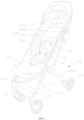
- a first embodiment of the present disclosure provides a carrier such as a stroller.
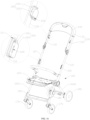
- the carrier includes a frame 100, a cover assembly 200, and a cover connection structure 300.
- the cover assembly 200 may be, for example, a seat cloth.
- the cover connection structure 300 is disposed between the frame 100 and the cover assembly 200 to detachably install the cover assembly 200 onto the frame 100.
- the cover connection structure 300 and the carrier are simple in structure, making detachment and installation easy.
- the frame 100 includes a handlebar 110, a seat member 120, a push handle assembly 130, a canopy bracket 140, a footrest 150, a front leg support 160a, and a rear leg support 160b. Both the seat member 120 and the canopy bracket 140 are connected to the push handle assembly 130, and the canopy bracket 140 is located above the seat member 120.
- the push handle assembly 130 has a structure generally in a shape of a U-shaped rod, including a push handle body 131 and two push handle rods 132 connected to two ends of the push handle body 131. Bottom ends of the two push handle rods 132 are respectively connected to opposite rear sides of the seat member 120.
- Two handlebars 110 are provided and are respectively disposed obliquely to a horizontal plane.
- Two front leg supports 160a are provided and are respectively disposed obliquely to the horizontal plane. Extension directions of the front leg support 160a and the handlebar 110 are substantially the same. Top ends of the two handlebars 110 are respectively connected to approximate middle portions of the two push handle rods 132. A bottom end of each handlebar 110 is connected to the front leg support 160a corresponding thereto.
- the footrest 150 is connected between the two front leg supports 160a. A bottom end of the footrest 150 is connected to two front wheel assemblies 170.
- the two front leg supports 160a are connected to opposite front sides of the seat member 120.
- the canopy bracket 140 also has a structure generally in a shape of a U-shaped rod. Two ends of the canopy bracket 140 are respectively connected to the top ends of the two handlebars 110.
- Two rear leg supports 160b are provided. Top ends of the two rear leg supports 160b are respectively connected to lower portions of the two handlebars 110, and bottom ends of the two rear leg supports 160b are respectively connected to two rear wheel assemblies 180.
- the frame 100 may further include a backrest assembly (not shown, e.g., a backrest plate).
- the backrest assembly is connected to the seat member 120 or the handlebar 110. The angle of inclination of the backrest assembly relative to the seat member 120 may be adjusted, allowing the rider's back to rest against the backrest assembly at a comfortable incline.
- the cover assembly 200 has a cloth structure, including a seat cover portion 210, a backrest cover portion 220, a first cover portion 230, and a second cover portion 240.
- Two first cover portions 230 are provided and are respectively connected to two sides of the backrest cover portion 220.
- the second cover portion 240 is connected to top sides of the two first cover portions 230 and a top side of the backrest cover portion 220.
- each first cover portion 230 in this embodiment is detachably connected to the corresponding handlebar 110
- the seat cover portion 210 may be connected to the seat member 120
- a top side of the second cover portion 240 may be connected to a support member 190 through a zipper or the like.
- a connection position between the cover assembly 200 and the frame 100 may be adjusted according to an actual requirement.
- the seat cover portion 210, the backrest cover portion 220, the first cover portions 230 on two sides, and the second cover portion 240 may be fixedly connected by sewing, so that the cover assembly 200 has a one-piece structure.
- the seat cover portion 210, the backrest cover portion 220, the first cover portions 230 on two sides, and the second cover portion 240 may be detachable from each other through zippers or other structures according to an actual requirement, which is not limited herein.
- the seat member 120 is provided with a seat cushion 410 thereon, and a back cushion 420 is connected to the seat cushion 410.
- the cover assembly 200 is connected to the frame 100, the seat cover portion 210 is located below the seat cushion 410, the seat cushion 410 may be further fixed to the seat member 120, the backrest cover portion 220 is located behind the back cushion 420, and the back cushion 420 is provided with a tie-down protection structure (such as a safety belt).
- the seat cover portion 210 and the seat member 120 may be connected by sleeving a pocket (not shown) provided at the bottom of the front end of the seat cover portion 210 over the front end of the seat member 120.
- the seat cushion 410 may be provided with a pocket (not shown) that further overlays and sleeves over the front ends of both the seat cover portion 210 and the seat member 120.
- the seat cushion 410 may be provided with other structures instead of the pocket to connect to the seat cover portion 210.
- the cover connection structures 300 are provided between the two first cover portions 230 and the handlebars 110 at the corresponding sides thereto.
- the cover connection structure 300 is not limited to being provided between the first cover portion 230 and the handlebar 110, and may also be provided between, for example, the seat cover portion 210 and the seat member 120, or between the second cover portion 240 and the canopy bracket 140, among others, which is not limited in the present disclosure.
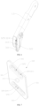
- the fixing base 310 includes a fixing body 311 and mounting portions 312 connected to two sides of the fixing body 311.
- the fixing base 310 is an integrally formed structure.
- the fixing base 310 may alternatively be formed by connecting a fixing body 311 and mounting portions 312 on two sides that are independent from each other.
- the handlebar 110 is provided with a concave section 111 that matches a shape of the fixing base 310, and the fixing base 310 is mounted within the concave section 111, thereby minimizing the space the fixing base 310 occupies and contributing to a more streamlined and aesthetically pleasing design for the carrier as a whole.
- the two mounting portions 312 of the fixing base 310 are respectively mounted in two concave sections 111 through fasteners (not shown).
- a side of the fixing body 311 facing away from the handlebar 110 is provided with a sliding groove 313.
- the sliding groove 313 includes a first groove portion 3131 and two second groove portions 3132 on two sides of the first groove portion 3131.
- the first groove portion 3131 is generally a parallelogram groove. One end of the first groove portion 3131 extends through an upper side of the fixing base 310.
- the first groove portion 3131 further has an abutting edge 3131a close to a lower side of the fixing base 310.
- both the upper side of the fixing base 310 and the abutting edge 3131a extend along an extension direction of the handlebar 110 which is oblique to the horizontal plane.
- the other two opposite side walls of the first groove portion 3131 are generally perpendicular to the horizontal plane, and the second groove portions 3132 are provided on the two opposite side walls.
- the two second groove portions 3132 also extend through the upper side of the fixing base 310. That is, the first groove portion 3131 and the two second groove portions 3132 all extend through the upper side of the fixing base 310 to form a T-shaped insertion port 3133.
- the insertion port 3133 is disposed opposite to the abutting edge 3131a.
- the sliding groove 313 is provided with a protruding portion 314 therein. In this embodiment, the protruding portion 314 is provided at substantially a center of a groove surface of the first groove portion 3131 facing the engaging member 320.
- an angle between the first edge 321 and the second edge 322 adjacent to each other is greater than or less than 90 degrees.
- the shape of the engaging member 320 is not limited to a parallelogram, and may alternatively be a trapezoid, a square, or other shapes, as long as the engaging member can be movably engaged with the fixing base 310, which is not limited in the present disclosure.
- a recessed portion 323 that can be engaged with the protruding portion 314 is further provided substantially in the middle of the engaging member 320.
- the engaging member 320 When the engaging member 320 is inserted in place, that is, when one of the second edges 322 of the engaging member 320 abuts against the abutting edge 3131a, the protruding portion 314 of the fixing base 310 and the recessed portion 323 of the engaging member 320 are exactly engaged with each other, and the engaging member 320 returns to its original shape. After the engaging member 320 is engaged in place, at least a part of the engaging member 320 is exposed above the insertion port 3133, thereby facilitating the detachment of the cover assembly 200.
- the part of the engaging member 320 exposed above the insertion port 3133 may be grasped and pulled upward to remove the engaging member 320.
- the engaging member 320 presses against the protruding portion 314 and deforms to some extent, so that the engaging member 320 can be withdrawn from the sliding groove 313 under an external force.
- the engaging member 320 is completely withdrawn from the sliding groove 313, the engaging member 320 returns to its original shape. In this way, the detachment of the cover assembly 200 from the frame 100 is realized, thereby facilitating cleaning or replacement of the cover assembly 200.
- the insertion port 3133 is located on an upper side of the abutting edge 3131a, which helps prevent the engaging member 320 from sliding out of the insertion port 3133 during the use of the cover connection structure 300.
- the insertion port 3133 may alternatively be located at another position such as on a left side or a lower side of the abutting edge 3131a.
- the positions of the protruding portion 314 and the recessed portion 323 may alternatively be interchanged. That is, the protruding portion 314 may be provided on the engaging member 320, and the recessed portion 323 may be provided on the fixing base 310.
- the engaging member 320 is fixed to the cover assembly 200 by sewing.
- the engaging member 320 is provided with a connecting portion 324, and the cover assembly 200 is sewn with the connecting portion 324.
- the engaging member 320 is provided with two connecting portions 324, and the two connecting portions 324 are respectively located on upper and lower sides of the recessed portion 323. That is, the two connecting portions 324 are respectively disposed proximate to the two second edges 322 of the engaging member 320.
- the two connecting portions 324 are parallel to the two second edges 322 of the engaging member 320, and lengths of the two connecting portions 324 are substantially equal.
- the two connecting portions 324 are at least partially misaligned in a direction parallel to the second edge 322. In this way, a stress-bearing region of the sewing thread can be increased, and firmness of the connection of the engaging member 320 can be improved.
- each of the two connecting portions 324 is provided with an elongated groove 325.
- the sewing thread can be accommodated in the groove 325, which prevents the groove surface of the first groove portion 3131 from being spaced apart from the surface of the engaging member 320, thereby ensuring that the engagement between the protruding portion 314 and the recessed portion 323 is not affected.
- a surface of the engaging member 320 in this embodiment fitting the cover assembly 200 is a flat surface.
- the connecting portion 324 of the engaging member 320 is provided with a plurality of sewing holes 3251.
- a plurality of sewing holes 3251 may be provided in the connecting portion 324 in advance before the connecting portion 324 is sewn with the cover assembly 200, which facilitates the sewing thread to pass through the cover assembly 200 and the sewing hole 3251 to sew the cover assembly 200 with the engaging member 320.
- the thickness and the material of the engaging member 320 allow a needle (not shown) to pierce through the engaging member 320, for example, if the engaging member is made of a plastic material, the sewing hole 3251 may not be provided in advance. The sewing thread may directly pass through the cover assembly 200 and the bottom of the groove 325 through the needle (not shown) to sew the cover assembly 200 with the engaging member 320.
- more than two or fewer than two connecting portions 324 may be provided.
- the two connecting portions 324 may alternatively be disposed proximate to the two first edges 321 of the engaging member 320 and extend along a direction parallel to the two first edges 321, or the two connecting portions 324 may be disposed in a cross shape, which is not limited in the present disclosure.
- lengths of the two connecting portions 324 are substantially the same, and distances between two ends of the two connecting portions 324 and the two first edges 321 are substantially the same. Since the two second edges 322 are at least partially misaligned, the two connecting portions 324 are at least partially misaligned in a direction parallel to the second edge 322. In other embodiments not shown, the lengths of the two connecting portions 324 may alternatively be different. Alternatively, in an embodiment where the engaging member 320 is in a shape of a square, the two connecting portions 324 are at least partially misaligned by making the lengths of the two connecting portions 324 different or making distances between the two connecting portions 324 and square edges different.
- At least one cover connection structure 300 is provided between the two first cover portions 230 and a part of the frame 100 on corresponding sides thereof.
- the cover connection structures 300 are disposed at intervals, which helps improve stability and reliability of the connection of the first cover portion 230 to the frame 100.
- the first cover portion 230 is smoother after being connected to the frame 100, which helps improve ornamental appearance of the carrier.
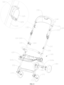
- FIG. 8 is a perspective view of a carrier provided according to a second embodiment of the present disclosure, with the cover assembly 200 removed.
- the carrier may include a frame 100, a cover assembly 200 (which can be referred to the relevant drawings in the first embodiment), and a cover connection structure 300.
- the carrier in this embodiment is a variation of the carrier in the first embodiment above. Unless there is a contradiction, structures of the components and the connection relationships between the components in this embodiment can be referred to the description in the first embodiment above. The following mainly describes the differences between this embodiment and the first embodiment above.
- the frame 100 is varied, and the difference mainly lies in that the structure and the connection relationship of the push handle assembly 130 are slightly different.
- the push handle assembly 130 also includes a push handle body 131 and two push handle rods 132 connected to two ends of the push handle body 131, however, unlike the first embodiment, the bottom ends of the two push handle rods 132 are not respectively connected to the opposite rear sides of the seat member 120. Instead, in this embodiment, the bottom ends of the two push handle rods 132 are respectively connected to top ends of the handlebars 110 on corresponding sides.
- the angles between the two push handle rods 132 and the handlebars 110 on the corresponding sides are approximately 180 degrees.
- the two push handle rods 132 may be regarded as extending along the same straight line as the handlebars 110 on the corresponding sides.
- the cover connection structure 300 is further varied in this embodiment. Similarly, the following specific description is focused on one of the cover connection structures 300 as an example.
- the fixing base 310 is provided with the limiting protrusion 315 or the mounting slot 326
- the mounting slot 326 or the limiting protrusion 315 on the engaging member 320 can be engaged with the limiting protrusion 315 or the mounting slot 326 on the fixing base 310.
- the fixing base 310 is provided with the limiting protrusion 315
- the engaging member 320 is provided with the mounting slot 326
- one end of the mounting slot 326 extends through the engaging member 320 to form a mounting port 3263.
- the engaging member 320 can be slidably sleeved outside the limiting protrusion 315 through the mounting port 3263 by the mounting slot 326, thereby detachably connecting the engaging member 320 to the fixing base 310 and finally detachably mount the cover assembly 200 to onto the frame 100.
- the concave section 111 may be omitted from the frame 100, instead, the fixing base 310 is provided with a mounting hole 316 and is directly mounted to the frame 100 by a fastener passing through the mounting hole 316.
- the frame 100 is also provided with the concave section 111 at a position wherein it connects with the fixing base 310, and the mounting hole 316 in the fixing base 310 is configured to allow a fastener to pass through to mount the fixing base 310 within the concave section 111 of the frame 100.
- the engaging member 320 is provided with a connecting perforation 328 that is configured to allow a webbing (not shown in the figure) to pass through, and the webbing passed through the connecting perforation 328 is configured to be connected to the cover assembly 200.
- the webbing passed through the connecting perforation 328 may be securely connected or detachably connected to the cover assembly 200.
- the connection manner of the two includes, but is not limited to, sewing or glue bonding.
- connection manner of the two includes, but is not limited to, tying the webbing to the cover assembly 200 or using other connection structures (such as a pair of snap buttons or a pair of adhesive buckles).
- the engaging member 320 may alternatively be provided with the connecting portion 324 in the first embodiment above, with the connecting perforation 328 omitted. In this way, the connection of the engaging member 320 with the cover assembly 200 can also be achieved.
- the shape of the connecting perforation 328 is not limited, which may be a circular hole, a waist-shaped hole, or the like.
- the position of the connecting perforation 328 on the engaging member 320 is not specifically limited.
- the connecting perforation 328 may be located at a lower end portion of the engaging member 320 and proximate to the mounting port 3263.
- an extension direction of the connecting perforation 328 intersects with a sliding direction of the limiting protrusion 315 relative to the mounting slot 326.
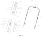
- the limiting protrusion 315 includes a first convex portion 3151 and a second convex portion 3152 connected to each other.
- the second convex portion 3152 protrudes relative to a periphery of the first convex portion 3151 to form a limiting edge 3153.
- the first convex portion 3151 is connected to the fixing base 310.
- the second convex portion 3152 and the fixing base 310 are spaced apart to form a limiting concave portion 3154.
- the mounting slot 326 includes a first groove body 3261 and a second groove body 3262 disposed on a periphery of the first groove body 3261 and in communication with the first groove body 3261.
- Both the first groove body 3261 and the second groove body 3262 extend through one end of the engaging member 320 to form a T-shaped mounting port 3263.
- the mounting slot 326 has a first wall body 3265, a second wall body 3266, and a third wall body 3267.
- the first wall body 3265 and a second wall body 3266 are opposite to and spaced apart in a direction perpendicular to a sliding direction of the limiting protrusion 315.
- the first wall body 3265 is located at a side of the second wall body 3266 close to the fixing base 310.
- the third wall body 3267 extends in the direction perpendicular to the sliding direction of the limiting protrusion 315 to connect the first wall body 3265 and the second wall body 3266.
- the first groove body 3261 extends through the first wall body 3265 in the direction perpendicular to the sliding direction of the limiting protrusion 315.
- the second groove body 3262 is defined by the first wall body 3265, the second wall body 3266, and the third wall body 3267 together. In this way, when the mounting slot 326 is engaged with the limiting protrusion 315, the limiting edge 3153 is positioned in the second groove body 3262, and a side wall (i.e., the first wall body 3265) of the second groove body 3262 is located in the limiting concave portion 3154.
- the limiting protrusion 315 can exit the mounting slot 326 only from the mounting port 3263, which can prevent detachment of the engaging member 320 from the fixing base 310 along a protruding direction of the limiting protrusion 315 after the two are connected.
- first convex portion 3151 and the second convex portion 3152 may be fixedly connected, such as integrally formed, welded, or bonded. Certainly, the first convex portion 3151 and the second convex portion 3152 may alternatively be detachably connected, such as engaged. Similarly, the connection relationship between the first convex portion 3151 and the fixing base 310 may be referred to the connection relationship between the first convex portion 3151 and the second convex portion 3152, which is not specifically limited herein.
- the mounting port 3263 is oriented downwards along a length direction of the push handle rod 132 or the handlebar 110.
- the mounting port 3263 may alternatively be oriented in another directions, for example, oriented forward or backward along the movement direction of the carrier.
- the first convex portion 3151 and the second convex portion 3152 each have a circular structure, so that the limiting edge 3153 and the limiting concave portion 3154 each have a ring-shaped structure.
- the first groove body 3261 and the second groove body 3262 each include an elongated first groove section 3264a and an arc-shaped second groove section 3264b, with one end of the first groove section 3264a in communication with the second groove section 3264b, and the other end of the first groove section 3264a forming the above mounting port 3263.
- the first groove section 3264a of the first groove body 3261 is in communication with the second groove section 3264b of the first groove body 3261
- the first groove section 3264a of the second groove body 3262 is in communication with the second groove section 3264b of the second groove body 3262
- the first groove section 3264a of the first groove body 3261 is in communication with the first groove section 3264a of the second groove body 3262
- the second groove section 3264b of the first groove body 3261 is in communication with the second groove section 3264b of the second groove body 3262
- the first groove section 3264a of the first groove body 3261 and the first groove section 3264a of the second groove body 3262 collectively form the mounting port 3263 with a T-shaped cross section.
- the limiting edge 3153 is limited in the second groove section 3264b of the second groove body 3262, and the first convex portion 3151 is positioned in the second groove section 3264b of the first groove body 3261.
- first wall body 3265, the second wall body 3266, and the third wall body 3267 each include an elongated wall portion and an arc-shaped wall portion.
- the first groove section 3264a of the first groove body 3261 extends through the elongated wall portion of the first wall body 3265 in a direction perpendicular to the sliding direction of the limiting protrusion 315
- the second groove section 3264b of the first groove body 3261 extends through the arc-shaped wall portion of the first wall body 3265 in a direction perpendicular to the sliding direction of the limiting protrusion 315.
- the elongated wall portions of the first wall body 3265, the second wall body 3266, and the third wall body 3267 collectively define the first groove section 3264a of the second groove body 3262.
- the arch-shaped wall portions of the first wall body 3265, the second wall body 3266, and the third wall body 3267 collectively define the second groove section 3264b of the second groove body 3262.
- the engaging member 320 can be caused to rotate relative to the fixing base 310 by rotating the limiting protrusion 315 in the second groove sections 3264b of the first groove body 3261 and the second groove body 3262. In other words, after the engaging member 320 is connected to the fixing base 310, the engaging member 320 can be operated to rotate relative to the fixing base 310.
- the engaging member 320 may rotate relative to the fixing base 310 around a central axis of the second convex portion 3152.
- the first cover portion 230 may be adjusted by rotating the engaging member 320 to eliminate the distortion of the first cover portion 230.
- the flexibility of the fixed connection of the first cover portion 230 is improved.
- the cover assembly 200 may be moved with the backrest, and a part of the cover assembly 200 connected to the engaging member 320 may rotate to some extent. In this case, the engaging member 320 can rotate relative to the fixing base 310 to reduce the twisting and wrinkling of the cover assembly 200 at the engaging member 320.
- first convex portion 3151 and the second convex portion 3152 are coaxially disposed. That is, central axes of the two are collinear.
- the above mounting hole 316 sequentially extends through the first convex portion 3151, the second convex portion 3152, and the fixing base 310, and an axis of the mounting hole 316 is located on the central axes of the first convex portion 3151 and the second convex portion 3152.
- an arc-center distance of the second groove section 3264b of the second groove body 3262 is greater than or equal to a radius of the second convex portion 3152
- an arc-center distance of the second groove section 3264b of the first groove body 3261 is greater than or equal to a radius of the first convex portion 3151. This facilitates the second convex portion 3152 to enter the second groove section 3264b of the second groove body 3262, and facilitate the first convex portion3151 to enter the second groove section 3264b of the first groove body 3261.
- the engaging member 320 is provided with a limiting structure 327.
- the limiting protrusion 315 overcomes the limiting structure 327 to move from the mounting port 3263 into the mounting slot 326.
- the limiting structure 327 includes a limiting portion 3271 and a hollowed-out portion 3272.
- the limiting portion 3271 is disposed on one or both of opposite side walls of the first groove body 3261.
- a surface of the first wall body 3265 facing the first groove body 3261 may be formed with the limiting portion 3271, and the limiting portion 3271 may be in a form of a limiting convex formed on the surface of the first wall body 3265 facing the first groove body 3261.
- the hollow out portion 3272 is provided at a position on one or both of opposite side walls of the first groove body 3261 corresponding to the limiting portion 3271. More specifically, the hollow out portion 3272 is formed on a side of the first wall body 3265 facing the fixing base 310, and extends through the first wall body 3265 in a direction perpendicular to the sliding direction of the limiting protrusion 315.
- the engaging member 320 can move relative to the fixing base 310, that is, the limiting protrusion 315 can move relative to the engaging member 320 from the mounting port 3263 to the interior of the mounting slot 326.
- the second convex portion 3152 is firstly inserted into the first groove section 3264a of the second groove body 3262, while the first convex portion 3151 is inserted into the first groove section 3264a of the first groove body 3261.
- the limiting portions 3271 When the first convex portion 3151 presses against the two limiting portions 3271, the limiting portions 3271 gradually move toward the hollow out portion 3272 such that the limiting portions 3271 elastically deforms, and the hollow out portion 3272 provides a space required for the movement of the limiting portions 3271.
- the two limiting portions 3271 are reset to limit the first convex portion 3151 in the second groove section 3264b of the first groove body 3261.
- the engaging member 320 and the fixing base 310 may be kept relatively fixed, preventing easy withdrawal of the limiting protrusion 315 from the mounting slot 326 through the mounting port 3263.
- the engaging member 320 may be pushed or pulled in the opposite direction (that is, generally in an obliquely upward direction), so that the limiting protrusion 315 can be withdrawn from the mounting port 3263 of the mounting slot 326 in the process of the engaging member 320 moving relative to the fixing base 310.
- the first convex portion 3151 presses against the limiting portion 3271 again to cause the limiting portion 3271 to gradually move toward the hollow out portion 3272 such that the limiting portion 3271 deforms to some extent.
- the hollow out portion 3272 and the limiting portion 3271 are reset to original shapes and positions.
- a side of the engaging member 320 facing the mounting slot 326 is provided with a rib 329.
- the rib 329 is disposed on, for example, a surface of the first wall 3265 facing the fixing base 310.
- the rib 329 can effectively prevent the problem of unstable engagement between the fixing base 310 and the engaging member 320 that may be caused when the end face of the limiting protrusion 315 and a wall of the mounting slot 326 do not fully fit. In other words, the rib 329 can effectively improve reliability of engagement of the engaging member 320 with the limiting protrusion 315.
- the above cover connection structures 300 are provided between the two first cover portions 230 and the handlebars 110 and/or the push handle rods 132 on corresponding sides thereto.
- the cover connection structures 300 are provided between the two first cover portions 230 and both the handlebars 110 and the push handle rods 132 on corresponding sides thereto. In this way, reliability of the connection between the first cover portion 230 and the frame 100 can be improved, the first cover portion 230 is smoother after being connected to the frame 100, which helps improve ornamental appearance of the carrier.
- FIG. 12 is a perspective view of a carrier provided according to a third embodiment of the present disclosure, with the cover assembly 200 removed.
- the carrier may include a frame 100, a cover assembly 200 (which can be referred to the relevant drawings in the first embodiment), and a cover connection structure 300.
- the carrier in this embodiment is a variation of the carrier in the second embodiment above. Unless there is a conflict, structures of the components and the connection relationships between the components in this embodiment can be referred to the description in the second embodiment above. The following mainly describes the differences between this embodiment and the second embodiment above.
- the first convex portion 3151 and the second convex portion 3152 each have an elongated structure.
- the first convex portion 3151 and the second convex portion 3152 each extend along a length direction of the handlebar 110 and/or the push handle rod 132.
- top ends of the first convex portion 3151 and the second convex portion 3152 are arc-shaped.
- the second groove section 3264b of the second groove body 3262 has an abutting edge 3131a opposite to the mounting port 3263.
- the top end of the second convex portion 3152 abuts against the abutting edge 3131a, and the limiting edge 3153 is limited in the first groove section 3264a and the second groove section 3264b of the second groove body 3262.
- the abutting edge 3131a is arc-shaped, with a curvature that matches a curvature of an outer edge of the top end of the second convex portion 3152.
- the top ends of the first convex portion 3151 and the second convex portion 3152 are arc-shaped, which facilitates quick and accurate insertion of the limiting protrusion 315 into the mounting slot 326 through the mounting port 3263, improving the rapidness of the connection between the engaging member 320 and the fixing base 310.
- the top end of the first convex portion 3151 is arc-shaped, in the case of abutment against the limiting portion 3271, it is conducive to improving smoothness of the movement of the limiting portion 3271 in the direction close to the hollow out portion 3272.
- the second groove section 3264b may be in other shapes, for example, both the second groove section 3264b and the first groove section 3264a have an elongated structure, which is not specifically limited herein.
- the first convex portion 3151 is provided with an inwardly concave notch 31511.
- the notch 31511 is configured to be in engagement fit with the limiting portion 3271 of the limiting structure 327.
- the second convex portion 3152 is firstly inserted into the first groove section 3264a of the second groove body 3262, while the first convex portion 3151 is inserted into the first groove section 3264a of the first groove body 3261.
- the limiting portions 3271 gradually move toward the hollow out portion 3272 such that the limiting portions 3271 elastically deforms, wherein the hollow out portion 3272 provides a required space for the movement of the limiting portions 3271.
- the engaging member 320 moves in place, that is, when the abutting edge 3131a of the second groove body 3262 on the engaging member 320 abuts against the top end of the second convex portion 3152, the limiting portion 3271 on the side wall of the first groove body 3261 and the notch 31511 on the first convex portion 3151 are just engaged with each other, at the same time, the limiting portion 3271 and the hollow out portion 3272 are both reset to original positions and shapes.
- the engaging member 320 and the fixing base 310 may be kept relatively fixed, preventing easy withdrawal of the limiting protrusion 315 from the mounting slot 326 through the mounting port 3263.
- the first convex portion 3151 in the movement pushes the limiting portion 3271 to gradually move toward the hollow out portion 3272 such that the limiting portion 3271 is withdrawn from the notch 31511. Once the first convex portion 3151 is disengaged from the limiting portion 3271, both the hollow out portion 3272 and the limiting portion 3271 can return to their original shapes and positions.
- the connecting perforation 328 is a waist-shaped hole, and an extension direction of the connecting perforation 328 is generally parallel to a sliding direction of the limiting protrusion 315 relative to the mounting slot 326.
- the connecting perforation 328 is located on a side portion of the engaging member 320, and the connecting perforation 328 may be regarded as being parallel to the first groove section 3264a and located outside of the first groove section 3264a.
- the connecting perforation 328 may alternatively be in other shapes.
- the position of the connecting perforation 328 may also be referred to the position of the connecting perforation 328 in the second embodiment.
- the fixing base 310 is provided with two mounting holes 316 in a length direction thereof, which helps improve the stability of the mounting of the fixing base 310 to the frame 100.
- the frame 100 is also provided with the concave section 111 at a position for connection with the fixing base 310, and the two mounting holes 316 are configured to allow fasteners to pass through to mount the fixing base 310 in the concave section 111 of the frame 100.
- the concave section 111 on the frame 100 may be omitted.
- the above cover connection structures 300 are provided between the two first cover portions 230 and both the handlebars 110 and the push handle rods 132 on corresponding sides.
- FIG. 16 is a perspective view of a carrier provided according to a fourth embodiment of the present disclosure, with the cover assembly 200 removed.
- the carrier may include a frame 100, a cover assembly 200 (which can be referred to the relevant drawings in the first embodiment), and a cover connection structure 300.
- the carrier in this embodiment is a varation of the carriers in the second embodiment and the third embodiment above. Unless there is a conflict, structures of the components and the connection relationships between the components in this embodiment can be referred to the description in the second embodiment and the third embodiment above. The following mainly describes the differences between this embodiment and the second embodiment and the third embodiment above.
- the cover connection structures 300 included in the carrier includes two structures. Specifically, the cover connection structures 300 in the second embodiment above are provided between the two first cover portions 230 and the push handle rods 132 on corresponding sides thereto. At the same time, the cover connection structures 300 in the third embodiment above are provided between the two first cover portions 230 and the handlebars 110 on corresponding sides thereto.
- a proximal upper-end region of the first cover portion 230 is connected to the frame 100 through the cover connection structure 300 shown in the second embodiment (which may be referred to as a first cover connection structure 300), and a proximal lower-end region of the first cover portion 230 is connected to the frame 100 through the cover connection structure 300 shown in the third embodiment (which may be referred to as a second cover connection structure 300).
- cover connection structure 300 shown in the second embodiment which may be referred to as a first cover connection structure 300
- a proximal lower-end region of the first cover portion 230 is connected to the frame 100 through the cover connection structure 300 shown in the third embodiment (which may be referred to as a second cover connection structure 300).
- the cover connection structures 300 in the third embodiment above may be provided between the two first cover portions 230 and the push handle rods 132 on corresponding sides thereto.
- the cover connection structures 300 in the second embodiment above may be provided between the two first cover portions 230 and the handlebars 110 on corresponding sides thereto.
- the proximal upper-end region of the first cover portion 230 may be connected to the frame 100 through the second cover connection structure 300, and the proximal lower-end region of the first cover portion 230 may be connected to the frame 100 through the first cover connection structure 300.
- the above cover connection structures 300 and the carrier have at least the following technical effects.
- the above carrier includes the cover connection structures 300.
- the fixing base 310 is provided on the frame 100
- the engaging member 320 is provided on the cover assembly 200
- detachable mounting of the cover assembly 200 onto the frame 100 is realized by movable engagement of the engaging member 320 with the fixing base 310.
- the cover connection structure 300 is simple in structure, making detachment and installation convenient.
Landscapes
- Engineering & Computer Science (AREA)
- Chemical & Material Sciences (AREA)
- Combustion & Propulsion (AREA)
- Transportation (AREA)
- Mechanical Engineering (AREA)
- Public Health (AREA)
- Health & Medical Sciences (AREA)
- Environmental & Geological Engineering (AREA)
- Seats For Vehicles (AREA)
- Carriages For Children, Sleds, And Other Hand-Operated Vehicles (AREA)
- Casings For Electric Apparatus (AREA)
- Connector Housings Or Holding Contact Members (AREA)
- Connection Of Plates (AREA)
Applications Claiming Priority (2)
| Application Number | Priority Date | Filing Date | Title |
|---|---|---|---|
| CN202311135488 | 2023-09-04 | ||
| CN202410628028 | 2024-05-20 |
Publications (1)
| Publication Number | Publication Date |
|---|---|
| EP4516632A1 true EP4516632A1 (de) | 2025-03-05 |
Family
ID=92675974
Family Applications (1)
| Application Number | Title | Priority Date | Filing Date |
|---|---|---|---|
| EP24198467.3A Pending EP4516632A1 (de) | 2023-09-04 | 2024-09-04 | Abdeckungsverbindungsstruktur und träger |
Country Status (6)
| Country | Link |
|---|---|
| US (1) | US20250074495A1 (de) |
| EP (1) | EP4516632A1 (de) |
| JP (1) | JP2025036399A (de) |
| CN (1) | CN119551053A (de) |
| AU (1) | AU2024219360B2 (de) |
| TW (1) | TWI911883B (de) |
Citations (5)
| Publication number | Priority date | Publication date | Assignee | Title |
|---|---|---|---|---|
| JP2008162561A (ja) * | 2007-01-05 | 2008-07-17 | Baby Planet Llc | ベビーバギー |
| GB2470126A (en) * | 2009-05-07 | 2010-11-10 | Wonderland Nurserygoods Compan | Infant supporting apparatus and method of assembling a seat fabric and canopy |
| GB2573836A (en) * | 2018-05-16 | 2019-11-20 | Denument Associates Ltd | Infant stroller |
| US20210403072A1 (en) * | 2020-06-30 | 2021-12-30 | China Wonderland Nurserygoods Co., Ltd. | Storage assembly and child carrier therewith |
| CA3219983A1 (en) * | 2021-05-13 | 2022-11-17 | Wonderland Switzerland Ag | Child carriage with removable soft goods |
Family Cites Families (1)
| Publication number | Priority date | Publication date | Assignee | Title |
|---|---|---|---|---|
| AU4912697A (en) * | 1996-10-24 | 1998-05-15 | Mattel, Inc. | Soft goods fastener |
-
2024
- 2024-08-30 TW TW113132941A patent/TWI911883B/zh active
- 2024-09-03 US US18/823,060 patent/US20250074495A1/en active Pending
- 2024-09-03 CN CN202411227086.1A patent/CN119551053A/zh active Pending
- 2024-09-03 AU AU2024219360A patent/AU2024219360B2/en active Active
- 2024-09-04 EP EP24198467.3A patent/EP4516632A1/de active Pending
- 2024-09-04 JP JP2024152132A patent/JP2025036399A/ja active Pending
Patent Citations (5)
| Publication number | Priority date | Publication date | Assignee | Title |
|---|---|---|---|---|
| JP2008162561A (ja) * | 2007-01-05 | 2008-07-17 | Baby Planet Llc | ベビーバギー |
| GB2470126A (en) * | 2009-05-07 | 2010-11-10 | Wonderland Nurserygoods Compan | Infant supporting apparatus and method of assembling a seat fabric and canopy |
| GB2573836A (en) * | 2018-05-16 | 2019-11-20 | Denument Associates Ltd | Infant stroller |
| US20210403072A1 (en) * | 2020-06-30 | 2021-12-30 | China Wonderland Nurserygoods Co., Ltd. | Storage assembly and child carrier therewith |
| CA3219983A1 (en) * | 2021-05-13 | 2022-11-17 | Wonderland Switzerland Ag | Child carriage with removable soft goods |
Also Published As
| Publication number | Publication date |
|---|---|
| TW202511127A (zh) | 2025-03-16 |
| AU2024219360A1 (en) | 2025-03-20 |
| AU2024219360B2 (en) | 2026-03-05 |
| CN119551053A (zh) | 2025-03-04 |
| JP2025036399A (ja) | 2025-03-14 |
| US20250074495A1 (en) | 2025-03-06 |
| TWI911883B (zh) | 2026-01-11 |
Similar Documents
| Publication | Publication Date | Title |
|---|---|---|
| CN105752146B (zh) | 婴儿车 | |
| US6843498B2 (en) | Stroller | |
| US7131692B2 (en) | Detachable children vehicle seat | |
| US12060101B2 (en) | Basket and stroller with the basket | |
| EP1442956A1 (de) | Sitzkern für Kinderfürsorgevorrichtung | |
| WO2022117867A1 (en) | Joining structure and child safety seat including the same | |
| CN201271027Y (zh) | 儿童产品的安全带安装系统及具有该系统的儿童产品 | |
| US6669225B2 (en) | Infant retention member for a stroller | |
| US20250074495A1 (en) | Cover connection structure and carrier | |
| US6860555B2 (en) | Seat hammock of child-care instrument | |
| US20220363302A1 (en) | Backrest angle adjustment mechanism and infant carrier thereof | |
| EP1332956A2 (de) | Zusatzkindersitz für Fahrräder | |
| CN220308732U (zh) | 一种折叠椅 | |
| JP4731753B2 (ja) | 椅子における張り材の取付構造 | |
| EP4371852A1 (de) | Esstablett, esstabletthalter und kindertragevorrichtung | |
| CN223821770U (zh) | 儿童推车 | |
| CN211632559U (zh) | 顶篷杆快拆机构 | |
| JP2003135203A (ja) | 椅子の背凭れ装置 | |
| JP2002087277A (ja) | ベビーカー | |
| CN109984519B (zh) | 肩带高度调整机构及其幼儿载具 | |
| CN220694827U (zh) | 一种用于座椅的隐藏式调节伸缩机构 | |
| CN223614491U (zh) | 儿童餐椅支架及儿童餐椅 | |
| AU2023362504A1 (en) | Armrest and child carrier | |
| AU2024275207A1 (en) | Infant basket, top tether system, conneting structure and child safety seat | |
| CN121158030A (zh) | 一种束缚带、乘坐装置及儿童推车 |
Legal Events
| Date | Code | Title | Description |
|---|---|---|---|
| PUAI | Public reference made under article 153(3) epc to a published international application that has entered the european phase |
Free format text: ORIGINAL CODE: 0009012 |
|
| STAA | Information on the status of an ep patent application or granted ep patent |
Free format text: STATUS: REQUEST FOR EXAMINATION WAS MADE |
|
| 17P | Request for examination filed |
Effective date: 20240904 |
|
| AK | Designated contracting states |
Kind code of ref document: A1 Designated state(s): AL AT BE BG CH CY CZ DE DK EE ES FI FR GB GR HR HU IE IS IT LI LT LU LV MC ME MK MT NL NO PL PT RO RS SE SI SK SM TR |
|
| STAA | Information on the status of an ep patent application or granted ep patent |
Free format text: STATUS: EXAMINATION IS IN PROGRESS |
|
| 17Q | First examination report despatched |
Effective date: 20251020 |