EP4516495A1 - Verfahren zur herstellung eines windturbinenschaufel- oder windturbinenschaufelabschnitts und füllmaterialaufbringvorrichtung - Google Patents
Verfahren zur herstellung eines windturbinenschaufel- oder windturbinenschaufelabschnitts und füllmaterialaufbringvorrichtung Download PDFInfo
- Publication number
- EP4516495A1 EP4516495A1 EP23194280.6A EP23194280A EP4516495A1 EP 4516495 A1 EP4516495 A1 EP 4516495A1 EP 23194280 A EP23194280 A EP 23194280A EP 4516495 A1 EP4516495 A1 EP 4516495A1
- Authority
- EP
- European Patent Office
- Prior art keywords
- wind turbine
- filler
- turbine blade
- filler material
- application head
- Prior art date
- Legal status (The legal status is an assumption and is not a legal conclusion. Google has not performed a legal analysis and makes no representation as to the accuracy of the status listed.)
- Withdrawn
Links
Images


Classifications
-
- B—PERFORMING OPERATIONS; TRANSPORTING
- B29—WORKING OF PLASTICS; WORKING OF SUBSTANCES IN A PLASTIC STATE IN GENERAL
- B29D—PRODUCING PARTICULAR ARTICLES FROM PLASTICS OR FROM SUBSTANCES IN A PLASTIC STATE
- B29D99/00—Subject matter not provided for in other groups of this subclass
- B29D99/0025—Producing blades or the like, e.g. blades for turbines, propellers, or wings
-
- B—PERFORMING OPERATIONS; TRANSPORTING
- B29—WORKING OF PLASTICS; WORKING OF SUBSTANCES IN A PLASTIC STATE IN GENERAL
- B29C—SHAPING OR JOINING OF PLASTICS; SHAPING OF MATERIAL IN A PLASTIC STATE, NOT OTHERWISE PROVIDED FOR; AFTER-TREATMENT OF THE SHAPED PRODUCTS, e.g. REPAIRING
- B29C70/00—Shaping composites, i.e. plastics material comprising reinforcements, fillers or preformed parts, e.g. inserts
- B29C70/02—Shaping composites, i.e. plastics material comprising reinforcements, fillers or preformed parts, e.g. inserts comprising combinations of reinforcements, e.g. non-specified reinforcements, fibrous reinforcing inserts and fillers, e.g. particulate fillers, incorporated in matrix material, forming one or more layers and with or without non-reinforced or non-filled layers
- B29C70/021—Combinations of fibrous reinforcement and non-fibrous material
- B29C70/025—Combinations of fibrous reinforcement and non-fibrous material with particular filler
-
- B—PERFORMING OPERATIONS; TRANSPORTING
- B29—WORKING OF PLASTICS; WORKING OF SUBSTANCES IN A PLASTIC STATE IN GENERAL
- B29C—SHAPING OR JOINING OF PLASTICS; SHAPING OF MATERIAL IN A PLASTIC STATE, NOT OTHERWISE PROVIDED FOR; AFTER-TREATMENT OF THE SHAPED PRODUCTS, e.g. REPAIRING
- B29C70/00—Shaping composites, i.e. plastics material comprising reinforcements, fillers or preformed parts, e.g. inserts
- B29C70/04—Shaping composites, i.e. plastics material comprising reinforcements, fillers or preformed parts, e.g. inserts comprising reinforcements only, e.g. self-reinforcing plastics
- B29C70/28—Shaping operations therefor
- B29C70/54—Component parts, details or accessories; Auxiliary operations, e.g. feeding or storage of prepregs or SMC after impregnation or during ageing
-
- B—PERFORMING OPERATIONS; TRANSPORTING
- B29—WORKING OF PLASTICS; WORKING OF SUBSTANCES IN A PLASTIC STATE IN GENERAL
- B29C—SHAPING OR JOINING OF PLASTICS; SHAPING OF MATERIAL IN A PLASTIC STATE, NOT OTHERWISE PROVIDED FOR; AFTER-TREATMENT OF THE SHAPED PRODUCTS, e.g. REPAIRING
- B29C70/00—Shaping composites, i.e. plastics material comprising reinforcements, fillers or preformed parts, e.g. inserts
- B29C70/58—Shaping composites, i.e. plastics material comprising reinforcements, fillers or preformed parts, e.g. inserts comprising fillers only, e.g. particles, powder, beads, flakes, spheres
- B29C70/60—Shaping composites, i.e. plastics material comprising reinforcements, fillers or preformed parts, e.g. inserts comprising fillers only, e.g. particles, powder, beads, flakes, spheres comprising a combination of distinct filler types incorporated in matrix material, forming one or more layers, and with or without non-filled layers
- B29C70/603—Shaping composites, i.e. plastics material comprising reinforcements, fillers or preformed parts, e.g. inserts comprising fillers only, e.g. particles, powder, beads, flakes, spheres comprising a combination of distinct filler types incorporated in matrix material, forming one or more layers, and with or without non-filled layers and with one or more layers of pure plastics material, e.g. foam layers
-
- B—PERFORMING OPERATIONS; TRANSPORTING
- B29—WORKING OF PLASTICS; WORKING OF SUBSTANCES IN A PLASTIC STATE IN GENERAL
- B29C—SHAPING OR JOINING OF PLASTICS; SHAPING OF MATERIAL IN A PLASTIC STATE, NOT OTHERWISE PROVIDED FOR; AFTER-TREATMENT OF THE SHAPED PRODUCTS, e.g. REPAIRING
- B29C70/00—Shaping composites, i.e. plastics material comprising reinforcements, fillers or preformed parts, e.g. inserts
- B29C70/68—Shaping composites, i.e. plastics material comprising reinforcements, fillers or preformed parts, e.g. inserts by incorporating or moulding on preformed parts, e.g. inserts or layers, e.g. foam blocks
- B29C70/74—Moulding material on a relatively small portion of the preformed part, e.g. outsert moulding
- B29C70/745—Filling cavities in the preformed part
-
- B—PERFORMING OPERATIONS; TRANSPORTING
- B29—WORKING OF PLASTICS; WORKING OF SUBSTANCES IN A PLASTIC STATE IN GENERAL
- B29C—SHAPING OR JOINING OF PLASTICS; SHAPING OF MATERIAL IN A PLASTIC STATE, NOT OTHERWISE PROVIDED FOR; AFTER-TREATMENT OF THE SHAPED PRODUCTS, e.g. REPAIRING
- B29C73/00—Repairing of articles made from plastics or substances in a plastic state, e.g. of articles shaped or produced by using techniques covered by this subclass or subclass B29D
- B29C73/02—Repairing of articles made from plastics or substances in a plastic state, e.g. of articles shaped or produced by using techniques covered by this subclass or subclass B29D using liquid or paste-like material
-
- B—PERFORMING OPERATIONS; TRANSPORTING
- B33—ADDITIVE MANUFACTURING TECHNOLOGY
- B33Y—ADDITIVE MANUFACTURING, i.e. MANUFACTURING OF THREE-DIMENSIONAL [3D] OBJECTS BY ADDITIVE DEPOSITION, ADDITIVE AGGLOMERATION OR ADDITIVE LAYERING, e.g. BY 3D PRINTING, STEREOLITHOGRAPHY OR SELECTIVE LASER SINTERING
- B33Y10/00—Processes of additive manufacturing
-
- B—PERFORMING OPERATIONS; TRANSPORTING
- B33—ADDITIVE MANUFACTURING TECHNOLOGY
- B33Y—ADDITIVE MANUFACTURING, i.e. MANUFACTURING OF THREE-DIMENSIONAL [3D] OBJECTS BY ADDITIVE DEPOSITION, ADDITIVE AGGLOMERATION OR ADDITIVE LAYERING, e.g. BY 3D PRINTING, STEREOLITHOGRAPHY OR SELECTIVE LASER SINTERING
- B33Y80/00—Products made by additive manufacturing
-
- B—PERFORMING OPERATIONS; TRANSPORTING
- B05—SPRAYING OR ATOMISING IN GENERAL; APPLYING FLUENT MATERIALS TO SURFACES, IN GENERAL
- B05C—APPARATUS FOR APPLYING FLUENT MATERIALS TO SURFACES, IN GENERAL
- B05C5/00—Apparatus in which liquid or other fluent material is projected, poured or allowed to flow on to the surface of the work
- B05C5/02—Apparatus in which liquid or other fluent material is projected, poured or allowed to flow on to the surface of the work the liquid or other fluent material being discharged through an outlet orifice by pressure, e.g. from an outlet device in contact or almost in contact, with the work
- B05C5/0208—Apparatus in which liquid or other fluent material is projected, poured or allowed to flow on to the surface of the work the liquid or other fluent material being discharged through an outlet orifice by pressure, e.g. from an outlet device in contact or almost in contact, with the work for applying liquid or other fluent material to separate articles
- B05C5/0212—Apparatus in which liquid or other fluent material is projected, poured or allowed to flow on to the surface of the work the liquid or other fluent material being discharged through an outlet orifice by pressure, e.g. from an outlet device in contact or almost in contact, with the work for applying liquid or other fluent material to separate articles only at particular parts of the articles
- B05C5/0216—Apparatus in which liquid or other fluent material is projected, poured or allowed to flow on to the surface of the work the liquid or other fluent material being discharged through an outlet orifice by pressure, e.g. from an outlet device in contact or almost in contact, with the work for applying liquid or other fluent material to separate articles only at particular parts of the articles by relative movement of article and outlet according to a predetermined path
-
- B—PERFORMING OPERATIONS; TRANSPORTING
- B05—SPRAYING OR ATOMISING IN GENERAL; APPLYING FLUENT MATERIALS TO SURFACES, IN GENERAL
- B05D—PROCESSES FOR APPLYING FLUENT MATERIALS TO SURFACES, IN GENERAL
- B05D1/00—Processes for applying liquids or other fluent materials
- B05D1/26—Processes for applying liquids or other fluent materials performed by applying the liquid or other fluent material from an outlet device in contact with, or almost in contact with, the surface
-
- B—PERFORMING OPERATIONS; TRANSPORTING
- B05—SPRAYING OR ATOMISING IN GENERAL; APPLYING FLUENT MATERIALS TO SURFACES, IN GENERAL
- B05D—PROCESSES FOR APPLYING FLUENT MATERIALS TO SURFACES, IN GENERAL
- B05D1/00—Processes for applying liquids or other fluent materials
- B05D1/40—Distributing applied liquids or other fluent materials by members moving relatively to surface
- B05D1/42—Distributing applied liquids or other fluent materials by members moving relatively to surface by non-rotary members
-
- B—PERFORMING OPERATIONS; TRANSPORTING
- B29—WORKING OF PLASTICS; WORKING OF SUBSTANCES IN A PLASTIC STATE IN GENERAL
- B29C—SHAPING OR JOINING OF PLASTICS; SHAPING OF MATERIAL IN A PLASTIC STATE, NOT OTHERWISE PROVIDED FOR; AFTER-TREATMENT OF THE SHAPED PRODUCTS, e.g. REPAIRING
- B29C2793/00—Shaping techniques involving a cutting or machining operation
- B29C2793/009—Shaping techniques involving a cutting or machining operation after shaping
-
- B—PERFORMING OPERATIONS; TRANSPORTING
- B29—WORKING OF PLASTICS; WORKING OF SUBSTANCES IN A PLASTIC STATE IN GENERAL
- B29L—INDEXING SCHEME ASSOCIATED WITH SUBCLASS B29C, RELATING TO PARTICULAR ARTICLES
- B29L2031/00—Other particular articles
- B29L2031/08—Blades for rotors, stators, fans, turbines or the like, e.g. screw propellers
- B29L2031/082—Blades, e.g. for helicopters
- B29L2031/085—Wind turbine blades
-
- F—MECHANICAL ENGINEERING; LIGHTING; HEATING; WEAPONS; BLASTING
- F03—MACHINES OR ENGINES FOR LIQUIDS; WIND, SPRING, OR WEIGHT MOTORS; PRODUCING MECHANICAL POWER OR A REACTIVE PROPULSIVE THRUST, NOT OTHERWISE PROVIDED FOR
- F03D—WIND MOTORS
- F03D1/00—Wind motors with rotation axis substantially parallel to the air flow entering the rotor
- F03D1/06—Rotors
- F03D1/065—Rotors characterised by their construction elements
- F03D1/0675—Rotors characterised by their construction elements of the blades
-
- Y—GENERAL TAGGING OF NEW TECHNOLOGICAL DEVELOPMENTS; GENERAL TAGGING OF CROSS-SECTIONAL TECHNOLOGIES SPANNING OVER SEVERAL SECTIONS OF THE IPC; TECHNICAL SUBJECTS COVERED BY FORMER USPC CROSS-REFERENCE ART COLLECTIONS [XRACs] AND DIGESTS
- Y02—TECHNOLOGIES OR APPLICATIONS FOR MITIGATION OR ADAPTATION AGAINST CLIMATE CHANGE
- Y02P—CLIMATE CHANGE MITIGATION TECHNOLOGIES IN THE PRODUCTION OR PROCESSING OF GOODS
- Y02P70/00—Climate change mitigation technologies in the production process for final industrial or consumer products
- Y02P70/50—Manufacturing or production processes characterised by the final manufactured product
Definitions
- the present invention relates to a method for manufacturing a wind turbine blade or wind turbine blade section and to a filler material application apparatus for applying a hardenable filler material into an at least one groove running at least with a directional component along a spanwise direction of a raw wind turbine blade or raw wind turbine blade section.
- Wind turbine blades especially for offshore use, with the evolvement of technology continuously increase in size.
- current blades can reach a root diameter of approximately 4m, a blade length of well over 100m while typical chord lengths can reach up to 7m or even more.
- wind turbine blades are manufactured by lamination of multiple layers of fiber material in a mold having the shape of a negative impression of the outer blade geometry.
- a typical fiber material layup in a mold includes one or multiple air extraction means that are adapted to extract excess air from the mold before and/or during resin infusion of the fiber material layup.
- the air extraction means do not become part of the final blade structure but are an auxiliary production tool.
- Typical air extraction means include semipermeable membranes, i.e. membranes that allow gases, in particular air, to pass and block the passage of liquids, in particular resin.
- the permeable membranes are connected to a vacuum source located externally of the mold so that excess air from the mold can be extracted therefrom.
- filters are also referred to as "filters”.
- the air extraction means are typically placed in the mold with an extension along a spanwise or longitudinal direction so that the raw wind turbine blade after removing it from the mold has grooves at its outer surface running along the spanwise or longitudinal direction at the positions where the air extraction means have been placed in the mold.
- These grooves have to be filled with a hardenable filler material to restore the intended airfoil geometry of the final wind turbine blade which, as of today, still requires manual labor.
- the filler material is typically smoothened with a spatula so that as little filler material as possible protrudes from the grooves which, as of today, is done by manual labor as well.
- smoothening and hardening of the filler material excess filler material e.g. residual filler material protruding beyond the intended airfoil geometry and/or laterally outwardly from the groove, is ground off in a subsequent production step to restore the ideal airfoil geometry of the blade.
- the manual application of filler material is not only disadvantageous from a productivity perspective.
- the application of filler material is mainly done in an overhead position the execution as a manual labor step means an enormous physical strain for the involved workers.
- the substances used as a filler material may be hazardous to the health of workers.
- the retention of the manual labor steps implies a barrier for both the dimensions of the blades that can be produced and for any potential productivity gains.
- the method comprises the following steps:
- That the filler application head is positioned "over" the at least one groove in particular has the meaning that the filler application head is positioned near to the groove in a predefined distance that allows the dispenser nozzle to fill the hardenable filler material in the flowable state into a cavity provided by the groove.
- “Section” of the groove in particular refers to a longitudinal section of the groove.
- the filler application head in step c) might in particular be positioned over an end section of the at least one groove, wherein "end” might in particular mean a root side end or tip side end of the groove.
- the at least one groove might in particular have a depth between 1 mm and 10 mm, in particular between 2 mm and 5 mm.
- the at least one groove might be the result of previous process steps, in particular it might represent a negative impression of a volume in that air extraction means or "filters" have been placed in a mold for lamination of the raw wind turbine blade or raw wind turbine blade section.
- the hardenable filler material might comprise a suitable plastic material and can be provided in a paste-like state with a relatively high viscosity so that it sticks to the groove and does not flow away under the influence of gravity.
- the hardenable filler material might in particular comprise a 2 component system, in particular a 2 component epoxy system.
- the filler material source may in particular comprise two separate storage volumes for each component of the 2 component system, e.g. one storage volume for a resin and another storage volume for a hardener.
- the filler material source of the filler material application apparatus may in particular comprise a mixing device that is adapted to mix the two components from the separate storage volumes together to create the hardenable filler material in a flowable state.
- step e After the hardenable filler material has been filled into the groove in step e) it might slightly protrude above a cross-section of the airfoil geometry of the final wind turbine blade or wind turbine blade section wherein such residual amounts of filler material might be ground off in subsequent production steps after the filler material has hardened completely to bring the blade back to its target airfoil geometry.
- a raw wind turbine blade or raw wind turbine blade section might also be referred to as “green wind turbine blade” or “green wind turbine blade section”.
- the main process parameters of the filler material application apparatus include a feed speed at that the filler application head is moved along the spanwise direction and a feed rate of hardenable filler material through the dispenser nozzle. These process parameters might be individually controlled when executing the method in order to achieve the best possible filling result that requires as little as possible rework.
- the method according to the invention allows to fill grooves at raw wind turbine blades or blade sections fully automatic without the need for manual labor.
- This allows for significant productivity gains in the production of wind turbine blades as the filler material application apparatus used in the method according to the invention can perform the filling tasks quicker and with less downtime and/or without breaks.
- the method is also beneficial under a Health Safety Environment (HSE) perspective as overhead works in environments with potentially hazardous substances in the air are avoided. An operator controlling the equipment used in the method according to the invention might do this remote from the filling site in a clean environment.
- the method according to the invention allows for a more consistent filling quality as human errors are eliminated through the automation of the filling process.
- HSE Health Safety Environment
- the filler application head of the filler material application apparatus comprises at least one spatula, wherein step e) comprises smoothening a surface of the hardenable filler material after it has been filled to the groove with the at least one spatula as the filler application head is moved along the spanwise direction.
- the at least one spatula might in particular be fixed to the filler application head so that it can be moved along the spanwise direction together with the filler application head.
- the at least one spatula can be arranged behind the at least one dispenser nozzle with respect to a predefined movement direction along the spanwise direction.
- the filler application head may comprise multiple spatula segments.
- at least two spatula segments can be arranged at the filler application head neighboring each other along a circumferential direction of the blade or blade section.
- at least two spatula segments may be arranged spaced apart along the spanwise direction.
- the at least two spatula segments have a different extension in a direction running normally to a ground of the at least one groove.
- one of the spatula segments might reach closer to the groove than the other spatula segment which has the advantage that the surface of the hardenable filler material can be smoothened step by step.
- a shape of the spatula is adaptable at least with respect to a plane running perpendicular to the spanwise direction, wherein step e) comprises adapting the shape of the spatula so that it corresponds with a shape of a cross-section of an airfoil geometry of the wind turbine blade or wind turbine blade section at a given spanwise position.
- the shape of the spatula might be continuously adapted in step e) as the filler application head is moved along the spanwise direction to correspond with a local shape of a cross-section of the airfoil geometry of the wind turbine blade or wind turbine blade section.
- shape of a cross-section of an airfoil geometry herein in particular refers to the final blade geometry, i.e. the spatula in particular adopts a shape of the final blade.
- the at least one spatula is capable of adopting a negative shape of the airfoil geometry of the blade or blade section at a given spanwise position in a cross-section where the groove is located.
- the adaption of the shape of the spatula ensures that grooves located in convex and/or concave cross-sections of the raw wind turbine blade or raw wind turbine blade section can be filled with the hardenable filler material in the best possible way, i.e. without applying too much filler material that protrudes above a cross-section of the airfoil geometry of the final wind turbine blade or wind turbine blade section. This significantly reduces the effort to rework the filled groove and especially reduces later grinding efforts.
- the filler application head is moveable in a height direction with respect to an intended state of use of the filler material application apparatus, wherein step e) comprises continuously adjusting a height position of the filler application head as the filler application head is moved along the spanwise direction to correspond with a local height position of the groove.
- step e) comprises continuously adjusting a height position of the filler application head as the filler application head is moved along the spanwise direction to correspond with a local height position of the groove.
- typical heights at that the grooves are located during the filling process may reach from 3 m to 6 m.
- the raw wind turbine blade or raw wind turbine blade section can be fixed by a fixture in a predefined height over the ground so that the spanwise direction runs essentially parallel to the ground, wherein in particular a suction side and/or pressure side of the raw wind turbine blade or raw wind turbine blade section are located sidewards.
- Such a fixture might in particular be fixed to a root section of the raw wind turbine blade or blade section.
- the fixture can allow for a rotational movement of the raw wind turbine blade or blade section along the spanwise direction.
- steps c) to e) are executed at a pressure side and/or a suction side of the raw wind turbine blade or raw wind turbine blade section.
- the filler material application apparatus can be located sideways adjacent to the raw wind turbine blade or raw wind turbine blade section, in particular during execution of the method steps c) to e).
- the raw wind turbine blade or blade section might comprise more than one groove running at least with a directional component along a spanwise direction, for example at least one groove at a suction side and at least one groove at the pressure side and/or multiple grooves at the suction side and/or pressure side.
- the filling of grooves at the pressure side and the suction side may be done serially or simultaneously, wherein separate filler material application apparatuses can be located sideways adjacent to the raw wind turbine blade or raw wind turbine blade section at the pressure side and the suction side.
- Multiple grooves commonly provided at the pressure side or the suction side might be filled serially or simultaneously, e.g. by using separate filler material application apparatuses which are spaced along the spanwise direction of the blade.
- the filler application head of the filler material application apparatus may be rotatable at least along one axis, wherein the at least one axis in particular runs parallel to the spanwise direction, and wherein in particular step e) includes continuously adapting a rotational position of the filler application head as the filler application head is moved along the spanwise direction to ensure the dispenser nozzle and/or the spatula of the filler application head are oriented over the groove at a given spanwise position at a predefined filler application angle.
- the filler application head might have other rotational degrees of freedom of movement as well, e.g. other possible rotational axes are axes running perpendicularly to the spanwise direction, for example an axis running parallel to the chordwise direction and/or an axis being both oriented perpendicularly to the spanwise and the chordwise direction.
- other possible rotational axes are axes running perpendicularly to the spanwise direction, for example an axis running parallel to the chordwise direction and/or an axis being both oriented perpendicularly to the spanwise and the chordwise direction.
- the filler application head of the filler material application apparatus comprises multiple actuators arranged spaced apart, in particular along a circumferential direction of the raw wind turbine blade or raw wind turbine blade section, wherein the actuators are each adapted to locally apply a force on the spatula and wherein the actuators are used in step e) to adapt the shape of the spatula.
- the actuators can comprise pneumatic or hydraulic pressure cylinders.
- the actuators may comprise fluid tight expansion pockets that can be individually inflated by a pressurized fluid.
- the actuators may comprise electrical actuators, such as stepper motors. It is in particular possible that the actuators are mechanically connected to the spatula, the shape of which is actively adjusted by the actuators.
- the spatula may in particular comprise a plastic material, in particular rubber and/or a thermoplastic elastomer.
- a stiffness, in particular a bending stiffness, of the spatula can be in particular dimensioned so that the shape of the spatula with respect to a plane running perpendicular to the spanwise direction can be modified by the actuator's forces.
- the filler material application apparatus comprises at least one processing means adapted to at least individually control the actuators and/or the height position of the filler application head.
- the processing means may be implemented in hardware and/or in software. If said entity is implemented in hardware, it may be embodied as a device, e.g. as a computer or as a processor or as a part of a system, e.g. a computer system. If said entity is implemented in software it may be embodied as a computer program product, as a function, as a routine, as a program code or as an executable object.
- the processing means can be adapted to also control the feed rate of the hardenable filler material in a flowable state and/or the feed speed of the filler application head.
- the method comprises step ee) applying an optical marking on an outer surface of the raw wind turbine blade or raw wind turbine blade section in at least one region laterally neighboring the groove.
- the filler material application apparatus in particular the filler application head of the filler material application apparatus, may comprise
- step e) data from the optical sensor may be processed by the processing means to adapt the shape of the spatula by individually controlling the multiple actuators to ensure that as little as possible of the hardenable filler material protrudes from the groove and/or to adjust a height position of the filler application head.
- the optical marking might comprise a dot or line of light that is projected onto an outer surface of the raw wind turbine blade or raw wind turbine blade section in at least one region laterally neighboring the groove.
- the filler material application apparatus in particular the filler application head, might comprise at least one optical projection means, in particular a dot and/or line projection means, adapted to project said dot or line of light.
- the optical projection means can in particular include a laser and/or other types of focused light sources.
- the optical marking on the outer surface of the raw wind turbine blade or raw wind turbine blade section gives an indication of the area that is to be filled with the hardenable filler material and thus enables to position the filler application head at the right height position and/or to adjust the spatula to a shape that corresponds best with an intended airfoil geometry of the final blade or blade section.
- the optical marking might comprise a color marking in the at least one region laterally neighboring the groove, wherein the color marking might, for example, comprise a line of paint and/or an adhesive tape.
- Step ee) might be in particular executed during the execution of step e).
- Said at least one camera may alternatively or additionally be used for a quality check of the filled groove in that surface parameters of the filled groove are compared to predefined target values of surface parameters.
- a quality check can be in particular performed by the processing means of the filler material application apparatus. If the measured surface parameters show unacceptable deviations from the target values the processing means may effect a correction of the current process parameters, e.g. feed rate of the hardenable filler material, feed speed of the filler application head, height position and/or shape of the spatula, to bring the actual surface parameters of the filled groove back to the target values.
- the processing means might comprise software that comprises self-learning algorithms and/or components of artificial intelligence (AI) that learn based on control interventions in the past.
- AI artificial intelligence
- the filler material application apparatus can comprise a processing means operably coupled with at least one data source, wherein the data source comprises data describing a three-dimensional shape of an outer surface of the wind turbine blade or wind turbine blade section, wherein in step e) the filler application head is moved along the spanwise direction under continuous adaption of the height position of the filler application head and/or under continuous adaption of the shape of the spatula of the filler application head based on said data.
- the data describing a three-dimensional shape of an outer surface of the wind turbine blade or wind turbine blade section might in particular be stored in the data source as a typical 3D-CAD file, e.g. a Step-file or similar file formats that the skilled person deems appropriate.
- a filler material application apparatus for applying a hardenable filler material into an at least one groove running at least with a directional component along a spanwise direction of a raw wind turbine blade or raw wind turbine blade section is proposed.
- the filler material application apparatus according to the second aspect of the invention may be in particular adapted for use in a method according to the first aspect of the invention.
- the filler material application apparatus comprises:
- the filler material application apparatus may comprise at least one pump fluidically coupled to the filler material source and the fluid line, wherein the pump is adapted and configured to effect a flow of hardenable filler material from the filler material source to the at least one dispenser nozzle of the filler application head.
- the fluid line may comprise at least one pipe and/or at least one hose, in particular a flexible hose.
- the fluid line may comprise at least one flexible longitudinal portion that is adapted to compensate a movement of the filler application head, in particular in the height direction.
- the filler application head is mounted to an apparatus base that is moveable on the ground, wherein in particular the apparatus base comprises a drive system and wheels that allow movement of the apparatus base in the spanwise direction of the raw wind turbine blade or raw wind turbine blade section.
- the filler application head may be fixed to the apparatus base so that the filler application head can in particular be moved together with the apparatus base.
- the apparatus base may be either mounted on rails on the ground or the wheels may be placed directly on the ground.
- the drive system may include a guiding system, e.g. an optical guiding system with guide markings on the ground, to direct the movement of the apparatus base along an intended path along the spanwise direction of the blade or blade section.
- the filler application head By providing the filler application head with wheels it can be in particular ensured that a distance between the dispenser nozzle and the groove of the wind turbine blade or blade section stays constant as the filler application head is moved along the spanwise direction during operation of the filler material application apparatus.
- the wheels allow that at least a portion of the dead weight of the filler application head is supported by the blade or blade section so that the apparatus base and/or a mechanical link between the apparatus base and the filler application head is relieved from forces resulting from said dead weight of the filler application head.
- the filler application head may be guided along an extension of the groove with increased accuracy which helps to improve an overall groove filling quality.
- Fig. 1 shows a schematic side view of a raw wind turbine blade 1 with three grooves 2 running at least with a directional component along the spanwise direction S.
- the raw wind turbine blade 1 comprises a blade tip 11 and a blade root 12, wherein the blade 1 might be fixed by a fixture in a predefined height over the ground G at the root 12 during execution of the method according to the invention.
- the blade structure is hollow with at least one cavity on the inside and comprises a shell comprising multiple layers of fiber material and core material.
- the blade 1 comprises an airfoil geometry with a pressure side 13 and a suction side 14, wherein a section of the shell associated with the pressure side 13 and a section of the shell associated with the suction side 14 meet at a leading edge 15 and a trailing edge 16.
- Fig. 2a a cross-section in the plane A-A of a raw wind turbine blade 1 is shown, wherein the grooves 2 are unfilled which corresponds to a condition of the raw blade 1 as it is removed from a mold.
- the grooves 2 correspond to positions at which air extraction material or "filters" have been placed in the mold.
- the hardenable filler material 3 is applied to the grooves 2 so that the hollow space is completely filled which creates filled grooves 21.
- a surface of the filler material 3 might be smoothened with a spatula after filling the grooves 2 so that as little filler material 3 as possible protrudes beyond the intended airfoil geometry and/or laterally outwardly from the grooves 2. However, this cannot completely be avoided so that the filled grooves 21 might still have a protruding portion 31 of filler material 3 that subsequently has to be grinded off.
- Fig. 2c shows a condition of the blade 1 after grinding, wherein the protruding portion 31 of filler material 3 has been removed with an appropriate grinding means so that the blade 1 has an ideal airfoil geometry around its full circumference.
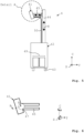
- Fig. 3 shows a schematic side view of the raw wind turbine blade 1 of Fig. 1 during execution of the method according to the invention with a filler material application apparatus 4 located sideways adjacent to the raw wind turbine blade 1.
- An upper groove 2 is still in an unfilled state whereas a lower groove 2 has already been partly filled and thus represents a partly filled groove 21.
- the filler material application apparatus 4 comprises a filler application head 41 with at least one dispenser nozzle 416 adapted and configured to dispense a hardenable filler material 3 into the groove 2.
- the filler material application apparatus 4 further comprises at least one filler material source 49 comprising the hardenable filler material in a flowable state, wherein the filler material source 49 is coupled to the dispenser nozzle 416 of the filler application head 41 through at least one fluid line 50 (see Fig. 5 and Fig. 7 ).
- the filler application head 41 is moveable at least along the spanwise direction S of the blade 1 in a feed direction F.
- the filler application head 41 is fixed to an apparatus base 42 having a drive system and wheels 43 that allow the apparatus base 42 to move along the spanwise direction S. As the apparatus base 42 moves, the filler application head 41 moves with it.
- the filler application head 41 is mounted at the apparatus base 42 through a support structure 44 and a filler application head connector 45 (see Fig. 5 ).
- One end of the filler application head connector 45 is arranged at the support structure 44 and another end of the filler application head connector 45 at the filler application head 41.
- the support structure 44 may in particular extend essentially vertical.
- the filler application head connector 45 may in particular extend essentially parallel to the ground G.
- the filler application head 41 is further moveable in a height direction H, wherein the required degree of freedom of movement can be provided by means of the support structure 44 and/or by means of the filler application head 41 itself. It is in particular possible that the support structure 44 comprises a linear drive system adapted to move the filler application head connector 45 in height.
- the filler application head 41 In order to initiate the filling process the filler application head 41 is positioned over a section of the groove 2 in a distance that allows the at least one dispenser nozzle 416 to dispense the hardenable filler material in a flowable state into a cavity provided by the groove 2. Then, a flow of hardenable filler material 3 from the filler material source 49 to the at least one dispenser nozzle 416 of the filler application head 41 is effected. Subsequently, the filler application head 41 is moved at least with a directional component in the spanwise direction S along an extension of the at least one groove 2, so that the groove 2 is filled with the hardenable filler material 3. After filling of the groove 2 with the hardenable filler material 3 the hardenable filler material 3 is hardened so that a filled groove 21 is created.
- the method according to the invention may comprise the application of an optical marking 46 on an outer surface of the raw wind turbine blade 1 in at least one region laterally neighboring the groove 2, in particular in two opposing regions laterally neighboring the groove 2.
- the filler material application apparatus 4 in particular the filler application head 41 of the filler material application apparatus 4, may comprise at least one optical sensor adapted to detect the optical marking, wherein said optical sensor may be operably coupled to a processing means of the filler material application apparatus 4. Data from the optical sensor may be processed by the processing means adjust the height position H of the filler application head 41 and/or to adapt the shape of a spatula 411 of the filler application head 41 (see Fig. 7 , Fig. 9 and Fig. 10 ).
- the optical marking 46 on the outer surface of the raw wind turbine blade 1 gives an indication of the area that is to be filled with the hardenable filler material 3 and thus enables to position the filler application head 41 at the right height position and/or to adjust the spatula 411 to a shape that corresponds best with an intended airfoil geometry of the final blade (see Fig. 9 and Fig. 10 ).
- the optical marking 46 may in particular comprise a dot or line of light
- the filler material application apparatus 4, in particular the filler application head 41 of the filler material application apparatus 4 may comprise at least one optical projection means, in particular a dot and/or line projection means, that is adapted and configured to project a dot or line of light 46 onto an outer surface of the raw wind turbine blade 1.
- FIG. 4 shows a schematic cross-sectional view of the raw wind turbine blade of Fig. 1 during execution of the method according to the invention.
- the filling is done at the suction side 14 of the blade 1.
- the filler application head 41 of the filler material application apparatus 4 is rotatable at least along an axis running parallel to the spanwise direction S so that the filler application head 41 can be oriented over the groove 2 at a given spanwise position S at a predefined filler application angle.
- the rotational position of the filler application head 41 may be continuously adapted to ensure the best possible filler material application along the full extension of the groove 2.
- the blade 1 has variable cross-sections over its length and eventually might be twisted the rotatability of the filler application head 41 has a significantly positive influence on the filling result.
- the filler application head connector 45 may in particular comprise a linear drive system that allows for a movement of the filler application head 41 essentially along a profile thickness direction T of the blade 1 in order to adjust a distance of the filler application head 41 from the groove 2 and/or to compensate for varying thickness of the blade 1 along the spanwise direction S.
- Fig. 5 the filler material application apparatus 4 is shown in more detail, whereas Fig. 6 shows Detail A of Fig. 5 .
- the filler material source 49 is arranged at the apparatus base 42.
- the filler material source 49 is connected through the fluid line 50 to the filler application head 41, in particular to a dispenser nozzle 416 of the filler application head 41 (see Fig. 7 ).
- at least one pump may be arranged at the apparatus base 42 that is adapted and configured to transport a volume of hardenable filler material to the filler application head 41.
- the filler material source 49 comprises two separate storage volumes for two components of a 2 component system, in particular of a 2 component epoxy system. In one of the storage volumes a resin is provided and in another storage volume a hardener.
- the filler material source 49 may comprise a mixing device that is adapted to mix the two components from the separate storage volumes together to create the hardenable filler material.
- the mixing device may be arranged at the apparatus base 42 as well. Alternatively, the two components from the separate storage volumes may be transported independently from each other through separate fluid lines to the filler application head 41 and mixed there.
- the filler application head 41 can be mounted to the filler application head connector 45 by means of a filler application head joint 47 having at least one rotational degree of freedom of movement along the spanwise direction S. Additionally or alternatively the joint 47 or a different joint might have a rotational degree of freedom of movement along the chordwise direction C and/or along an axis running perpendicularly to both the spanwise direction S and the chordwise direction C, for example the profile thickness direction T.
- the filler application head 41 is shown in a cross-sectional view through plane B-B depicted in Fig. 6 .
- the filler application head 41 comprises at least two wheels 48 that allow for a rolling movement of the filler application head 41 on an outer surface of the raw wind turbine blade 1.
- the wheels 48 are arranged spaced apart along the spanwise direction S respectively along the feed direction F. Additionally, further wheels may be provided with a spacing along the circumferential direction of the blade 1 with respect to an intended state of use of the filler material application apparatus 4.
- At least one dispenser nozzle 416 that is fluidically couplable to the filler material source 49 through the fluid line 50 is arranged between the two wheels 48.
- the wheels 48 ensure that a distance between the dispenser nozzle 416 and the groove 2 of the wind turbine blade 1 can be kept constant as the filler application head 41 is moved along the spanwise direction S of the blade 1 during operation of the filler material application apparatus 4.
- the filler application head 41 further comprises at least one spatula 411 that is adapted and configured to smoothen a surface of the hardenable filler material after it has been filled to the groove 2 as the filler application head 41 is moved along the spanwise direction S of the blade 1.
- the at least one spatula 411 is arranged behind the at least one dispenser nozzle 416 with respect to the feed direction F.
- the spatula 411 may comprise multiple spatula segments that are arranged at the filler application head 41 spaced apart along the spanwise direction S respectively along the feed direction F.
- An extension of the spatula segments in a direction running normally to a ground of the at least one groove 2 with respect to an intended state of use of the filler material application apparatus 4 might in particular decrease along the feed direction F so that the hardenable filler material within the groove 2 can be beneficially smoothened step by step.
- a shape of the spatula 411 is adaptable at least with respect to a plane running perpendicular to the spanwise direction S so that it corresponds with a shape of a cross-section of an airfoil geometry of the wind turbine blade 1 at a given spanwise position.
- the shape of the spatula 411 might be adapted before or after the filler application head 41 is placed over a section of the groove 2 to commence the filling procedure.
- the shape of the spatula 411 can be adaptable so that the spatula 411 can adopt a cross-sectional shape representing a negative of a cross-sectional shape of the airfoil geometry of the wind turbine blade 1 at a given spanwise position.
- the shape of the spatula 411 can be continuously adapted as the filler application head 41 is moved along the spanwise direction S to always correspond with a local shape of a cross-section of the airfoil geometry of the blade 1.
- Fig. 8 shows an alternative to Fig. 3 in that the filler application head 41 is not fixed to an apparatus base 42 but to a crane or gantry system 60 above the raw wind turbine blade 1.
- the crane or gantry system 60 allows movement of the filler application head 41 in the spanwise direction S of the raw wind turbine blade 1.
- the overall function of the filler application head 41 is however identical to the before described embodiments and therefore is not repeated.
- the crane or gantry system 60 may comprise a first beam 601 running along the spanwise direction S. On the first beam 601 a beam trolley 602 may be moveably arranged along the spanwise direction S.
- the beam trolley 602 may comprise one or multiple wheels that are adapted and configured to roll on the first beam 601.
- the beam trolley 602 may comprise a drive system, for example an electric drive system, that allows for a movement of the beam trolley 602 along the spanwise direction S.
- the filler application head 41 may be mounted to the beam trolley 602 by means of a support structure 603 which may in particular extend with a vertical component with regards to an intended state of use of the filler material application apparatus 4. As the beam trolley 602 moves along the extension of the first beam 601 the filler application head 41 moves with it.
- the crane or gantry system 60 may comprise a second beam extending perpendicular to the first beam's 601 extension, in particular along a thickness direction T of the raw wind turbine blade 1.
- the first beam 601 and/or the beam trolley 602 may be moveable along an extension of the second beam in order to further adjust a position of the filler application head 41, for example to compensate for varying thickness of the blade 1 along its longitudinal extension.
- the support structure 603 may comprise one or multiple beams and/or at least one rope or cable that are adapted and configured to mechanically couple the filler application head 41 to the beam trolley 602.
- the crane or gantry system 60 may be a portal crane.
- the filler application head 41 may be as well further moveable in a height direction H, wherein the required degree of freedom of movement can be provided by means of the support structure 603 and/or by means of the filler application head 41 itself.
- the support structure 603 comprises a linear drive system adapted to move the filler application head 41 in height.
- the height H adjustment might be carried out by varying a free hanging length of the rope or cable.
- the at least one rope or cable might be attached to at least one driven pulley at the beam trolley 602.
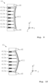
- Fig. 9 an embodiment of the filler application head 41 is shown as a cross-section through plane C-C depicted in Fig. 7 , wherein the sectional plane extends through the at least one spatula 411, in particular through one of the spatula segments.
- the filler application head 41 comprises multiple actuators 413a-g that are variable in length and mechanically coupled to the spatula 411.
- Each actuator 413a-g is adapted and configured to locally apply a force on the spatula 411.
- a shape of the spatula 411 can be adapted, e.g. to form a concave shape as it is shown in Fig.
- Fig. 9 or to form a convex shape as it is shown in Fig. 10 .
- the convexity and/or concavity in Fig. 9 and Fig. 10 are shown in an exaggerated way to illustrate the operation of the filler application head 41, although the convexity and/or concavity may be less pronounced in practice.
- This adaptability of the shape of the spatula 411 ensures that grooves 2 located in convex and/or concave cross-sections of the raw wind turbine blade 1 can be filled with the hardenable filler material in the best possible way, i.e. without applying too much filler material which particularly helps to reduce later effort to rework the filled groove by grinding.
- Fig. 11 shows a flow chart of an embodiment of the method according to the invention.
- the method comprises the following steps:
Landscapes
- Engineering & Computer Science (AREA)
- Chemical & Material Sciences (AREA)
- Mechanical Engineering (AREA)
- Composite Materials (AREA)
- Manufacturing & Machinery (AREA)
- Materials Engineering (AREA)
- Coating Apparatus (AREA)
- Wind Motors (AREA)
Priority Applications (4)
| Application Number | Priority Date | Filing Date | Title |
|---|---|---|---|
| EP23194280.6A EP4516495A1 (de) | 2023-08-30 | 2023-08-30 | Verfahren zur herstellung eines windturbinenschaufel- oder windturbinenschaufelabschnitts und füllmaterialaufbringvorrichtung |
| PCT/EP2024/072728 WO2025045572A1 (en) | 2023-08-30 | 2024-08-12 | Method for manufacturing a wind turbine blade or wind turbine blade section and filler material application apparatus |
| CN202480055533.1A CN121816258A (zh) | 2023-08-30 | 2024-08-12 | 用于制造风力涡轮机叶片或风力涡轮机叶片区段的方法和填料材料施加设备 |
| TW113132361A TW202516103A (zh) | 2023-08-30 | 2024-08-28 | 用於製造風力渦輪機葉片或風力渦輪機葉片區段之方法以及填充材料施加設備 |
Applications Claiming Priority (1)
| Application Number | Priority Date | Filing Date | Title |
|---|---|---|---|
| EP23194280.6A EP4516495A1 (de) | 2023-08-30 | 2023-08-30 | Verfahren zur herstellung eines windturbinenschaufel- oder windturbinenschaufelabschnitts und füllmaterialaufbringvorrichtung |
Publications (1)
| Publication Number | Publication Date |
|---|---|
| EP4516495A1 true EP4516495A1 (de) | 2025-03-05 |
Family
ID=87863108
Family Applications (1)
| Application Number | Title | Priority Date | Filing Date |
|---|---|---|---|
| EP23194280.6A Withdrawn EP4516495A1 (de) | 2023-08-30 | 2023-08-30 | Verfahren zur herstellung eines windturbinenschaufel- oder windturbinenschaufelabschnitts und füllmaterialaufbringvorrichtung |
Country Status (4)
| Country | Link |
|---|---|
| EP (1) | EP4516495A1 (de) |
| CN (1) | CN121816258A (de) |
| TW (1) | TW202516103A (de) |
| WO (1) | WO2025045572A1 (de) |
Citations (3)
| Publication number | Priority date | Publication date | Assignee | Title |
|---|---|---|---|---|
| EP1310351A1 (de) | 2001-11-13 | 2003-05-14 | Bonus Energy A/S | Verfahren zur Herstellung von Windmühlenflügeln |
| US20190338759A1 (en) * | 2016-12-20 | 2019-11-07 | Vestas Wind Systems A/S | Methods and systems for repairing wind turbine blades |
| WO2023280362A1 (en) * | 2021-07-09 | 2023-01-12 | Vestas Wind Systems A/S | Coating applicator tool used with robotic device for repairing leading edge damage on a wind turbine blade |
-
2023
- 2023-08-30 EP EP23194280.6A patent/EP4516495A1/de not_active Withdrawn
-
2024
- 2024-08-12 CN CN202480055533.1A patent/CN121816258A/zh active Pending
- 2024-08-12 WO PCT/EP2024/072728 patent/WO2025045572A1/en active Pending
- 2024-08-28 TW TW113132361A patent/TW202516103A/zh unknown
Patent Citations (3)
| Publication number | Priority date | Publication date | Assignee | Title |
|---|---|---|---|---|
| EP1310351A1 (de) | 2001-11-13 | 2003-05-14 | Bonus Energy A/S | Verfahren zur Herstellung von Windmühlenflügeln |
| US20190338759A1 (en) * | 2016-12-20 | 2019-11-07 | Vestas Wind Systems A/S | Methods and systems for repairing wind turbine blades |
| WO2023280362A1 (en) * | 2021-07-09 | 2023-01-12 | Vestas Wind Systems A/S | Coating applicator tool used with robotic device for repairing leading edge damage on a wind turbine blade |
Also Published As
| Publication number | Publication date |
|---|---|
| WO2025045572A1 (en) | 2025-03-06 |
| TW202516103A (zh) | 2025-04-16 |
| CN121816258A (zh) | 2026-04-07 |
Similar Documents
| Publication | Publication Date | Title |
|---|---|---|
| EP3212375B1 (de) | Schernetzformungssystem mit variablen formplatten | |
| EP3183102B1 (de) | Verfahren zur herstellung einer form für eine windturbinenschaufelhülle | |
| EP4367388B1 (de) | Beschichtungsapplikatorwerkzeug mit robotervorrichtung zur reparatur von vorderkantenschäden an einer windturbinenschaufel | |
| EP3134244B1 (de) | Windturbinenschaufelherstellungssystem und -verfahren | |
| JP2016221949A (ja) | 複合構造を自動的にレイアップするための装置及び方法 | |
| US11725624B2 (en) | Wind blade component bonding fixture | |
| US12070878B2 (en) | Modular molding units for fabrication of wind turbine blades | |
| WO2021121522A1 (en) | Automated device and method for repairing leading edge damage on wind turbine blade | |
| US20240181732A1 (en) | Pneumatically operated web lifting tongs | |
| EP4516495A1 (de) | Verfahren zur herstellung eines windturbinenschaufel- oder windturbinenschaufelabschnitts und füllmaterialaufbringvorrichtung | |
| CN118973801A (zh) | 用于使用纤维层片来生产风力涡轮机叶片的材料铺层设备和方法 | |
| US9950478B2 (en) | Method of fabricating a spar for a blade, and a method of fabricating a blade | |
| EP4516494A1 (de) | Verfahren zur herstellung eines windturbinenschaufel- oder windturbinenschaufelabschnitts und schleifvorrichtung | |
| CN113056361A (zh) | 用于制造风能设施的转子叶片的设备和方法以及风能设施 | |
| EP3744494B1 (de) | Form zur herstellung einer windturbinenschaufel und verfahren zur herstellung einer windturbinenschaufel | |
| JP7749660B2 (ja) | 風力タービンブレード部品を風力タービンブレードシェル部材に取り付けるためのシステム及び方法 | |
| JP4067574B2 (ja) | ヘリコプタメインロータブレードサブアセンブリを組み立てるための装置及び方法 | |
| EP4448265B1 (de) | Verfahren und vorrichtung zum beschneiden eines windturbinenblatt-produktionsflanschs | |
| WO2025131205A1 (en) | Coating applicator tool with a curved applicator nozzle | |
| EP4609989A1 (de) | Bearbeitung eines wurzelteils einer windturbinenschaufel | |
| EP4571095A1 (de) | System und verfahren zur herstellung von windturbinenschaufeln | |
| CN223989518U (zh) | 一种用于混凝土墩柱养护过程中输送水管的机械手 | |
| EP4241970A1 (de) | Vorrichtung und verfahren zur fasermattenabscheidung | |
| EP4501573A1 (de) | Bewegliche plattform und verfahren zur handhabung einer beweglichen plattform zur herstellung von windturbinenschaufeln | |
| CN121267997A (zh) | 一种可移动式风电叶片切割设备及其切割方法 |
Legal Events
| Date | Code | Title | Description |
|---|---|---|---|
| PUAI | Public reference made under article 153(3) epc to a published international application that has entered the european phase |
Free format text: ORIGINAL CODE: 0009012 |
|
| STAA | Information on the status of an ep patent application or granted ep patent |
Free format text: STATUS: THE APPLICATION HAS BEEN PUBLISHED |
|
| AK | Designated contracting states |
Kind code of ref document: A1 Designated state(s): AL AT BE BG CH CY CZ DE DK EE ES FI FR GB GR HR HU IE IS IT LI LT LU LV MC ME MK MT NL NO PL PT RO RS SE SI SK SM TR |
|
| STAA | Information on the status of an ep patent application or granted ep patent |
Free format text: STATUS: THE APPLICATION IS DEEMED TO BE WITHDRAWN |
|
| 18D | Application deemed to be withdrawn |
Effective date: 20250906 |