EP4516475A1 - Intermediate mold, mold unit, and injection molding machine - Google Patents
Intermediate mold, mold unit, and injection molding machine Download PDFInfo
- Publication number
- EP4516475A1 EP4516475A1 EP24187365.2A EP24187365A EP4516475A1 EP 4516475 A1 EP4516475 A1 EP 4516475A1 EP 24187365 A EP24187365 A EP 24187365A EP 4516475 A1 EP4516475 A1 EP 4516475A1
- Authority
- EP
- European Patent Office
- Prior art keywords
- mold
- section
- frame body
- rotating frame
- rotation drive
- Prior art date
- Legal status (The legal status is an assumption and is not a legal conclusion. Google has not performed a legal analysis and makes no representation as to the accuracy of the status listed.)
- Pending
Links
Images




Classifications
-
- B—PERFORMING OPERATIONS; TRANSPORTING
- B29—WORKING OF PLASTICS; WORKING OF SUBSTANCES IN A PLASTIC STATE IN GENERAL
- B29C—SHAPING OR JOINING OF PLASTICS; SHAPING OF MATERIAL IN A PLASTIC STATE, NOT OTHERWISE PROVIDED FOR; AFTER-TREATMENT OF THE SHAPED PRODUCTS, e.g. REPAIRING
- B29C45/00—Injection moulding, i.e. forcing the required volume of moulding material through a nozzle into a closed mould; Apparatus therefor
- B29C45/03—Injection moulding apparatus
- B29C45/04—Injection moulding apparatus using movable moulds or mould halves
- B29C45/0441—Injection moulding apparatus using movable moulds or mould halves involving a rotational movement
- B29C45/045—Injection moulding apparatus using movable moulds or mould halves involving a rotational movement mounted on the circumference of a rotating support having a rotating axis perpendicular to the mould opening, closing or clamping direction
-
- B—PERFORMING OPERATIONS; TRANSPORTING
- B29—WORKING OF PLASTICS; WORKING OF SUBSTANCES IN A PLASTIC STATE IN GENERAL
- B29C—SHAPING OR JOINING OF PLASTICS; SHAPING OF MATERIAL IN A PLASTIC STATE, NOT OTHERWISE PROVIDED FOR; AFTER-TREATMENT OF THE SHAPED PRODUCTS, e.g. REPAIRING
- B29C45/00—Injection moulding, i.e. forcing the required volume of moulding material through a nozzle into a closed mould; Apparatus therefor
- B29C45/03—Injection moulding apparatus
- B29C45/04—Injection moulding apparatus using movable moulds or mould halves
- B29C45/0441—Injection moulding apparatus using movable moulds or mould halves involving a rotational movement
-
- B—PERFORMING OPERATIONS; TRANSPORTING
- B29—WORKING OF PLASTICS; WORKING OF SUBSTANCES IN A PLASTIC STATE IN GENERAL
- B29C—SHAPING OR JOINING OF PLASTICS; SHAPING OF MATERIAL IN A PLASTIC STATE, NOT OTHERWISE PROVIDED FOR; AFTER-TREATMENT OF THE SHAPED PRODUCTS, e.g. REPAIRING
- B29C45/00—Injection moulding, i.e. forcing the required volume of moulding material through a nozzle into a closed mould; Apparatus therefor
- B29C45/17—Component parts, details or accessories; Auxiliary operations
- B29C45/26—Moulds
- B29C45/2602—Mould construction elements
-
- B—PERFORMING OPERATIONS; TRANSPORTING
- B29—WORKING OF PLASTICS; WORKING OF SUBSTANCES IN A PLASTIC STATE IN GENERAL
- B29C—SHAPING OR JOINING OF PLASTICS; SHAPING OF MATERIAL IN A PLASTIC STATE, NOT OTHERWISE PROVIDED FOR; AFTER-TREATMENT OF THE SHAPED PRODUCTS, e.g. REPAIRING
- B29C33/00—Moulds or cores; Details thereof or accessories therefor
- B29C33/0083—Electrical or fluid connection systems therefor
-
- B—PERFORMING OPERATIONS; TRANSPORTING
- B29—WORKING OF PLASTICS; WORKING OF SUBSTANCES IN A PLASTIC STATE IN GENERAL
- B29C—SHAPING OR JOINING OF PLASTICS; SHAPING OF MATERIAL IN A PLASTIC STATE, NOT OTHERWISE PROVIDED FOR; AFTER-TREATMENT OF THE SHAPED PRODUCTS, e.g. REPAIRING
- B29C45/00—Injection moulding, i.e. forcing the required volume of moulding material through a nozzle into a closed mould; Apparatus therefor
- B29C45/17—Component parts, details or accessories; Auxiliary operations
- B29C45/1742—Mounting of moulds; Mould supports
-
- B—PERFORMING OPERATIONS; TRANSPORTING
- B29—WORKING OF PLASTICS; WORKING OF SUBSTANCES IN A PLASTIC STATE IN GENERAL
- B29C—SHAPING OR JOINING OF PLASTICS; SHAPING OF MATERIAL IN A PLASTIC STATE, NOT OTHERWISE PROVIDED FOR; AFTER-TREATMENT OF THE SHAPED PRODUCTS, e.g. REPAIRING
- B29C45/00—Injection moulding, i.e. forcing the required volume of moulding material through a nozzle into a closed mould; Apparatus therefor
- B29C45/17—Component parts, details or accessories; Auxiliary operations
- B29C45/1756—Handling of moulds or mould parts, e.g. mould exchanging means
-
- B—PERFORMING OPERATIONS; TRANSPORTING
- B29—WORKING OF PLASTICS; WORKING OF SUBSTANCES IN A PLASTIC STATE IN GENERAL
- B29C—SHAPING OR JOINING OF PLASTICS; SHAPING OF MATERIAL IN A PLASTIC STATE, NOT OTHERWISE PROVIDED FOR; AFTER-TREATMENT OF THE SHAPED PRODUCTS, e.g. REPAIRING
- B29C45/00—Injection moulding, i.e. forcing the required volume of moulding material through a nozzle into a closed mould; Apparatus therefor
- B29C45/17—Component parts, details or accessories; Auxiliary operations
- B29C45/72—Heating or cooling
- B29C45/73—Heating or cooling of the mould
- B29C45/7312—Construction of heating or cooling fluid flow channels
-
- B—PERFORMING OPERATIONS; TRANSPORTING
- B29—WORKING OF PLASTICS; WORKING OF SUBSTANCES IN A PLASTIC STATE IN GENERAL
- B29C—SHAPING OR JOINING OF PLASTICS; SHAPING OF MATERIAL IN A PLASTIC STATE, NOT OTHERWISE PROVIDED FOR; AFTER-TREATMENT OF THE SHAPED PRODUCTS, e.g. REPAIRING
- B29C49/00—Blow-moulding, i.e. blowing a preform or parison to a desired shape within a mould; Apparatus therefor
- B29C49/02—Combined blow-moulding and manufacture of the preform or the parison
- B29C49/06—Injection blow-moulding
-
- B—PERFORMING OPERATIONS; TRANSPORTING
- B29—WORKING OF PLASTICS; WORKING OF SUBSTANCES IN A PLASTIC STATE IN GENERAL
- B29C—SHAPING OR JOINING OF PLASTICS; SHAPING OF MATERIAL IN A PLASTIC STATE, NOT OTHERWISE PROVIDED FOR; AFTER-TREATMENT OF THE SHAPED PRODUCTS, e.g. REPAIRING
- B29C45/00—Injection moulding, i.e. forcing the required volume of moulding material through a nozzle into a closed mould; Apparatus therefor
- B29C45/03—Injection moulding apparatus
- B29C45/04—Injection moulding apparatus using movable moulds or mould halves
- B29C45/0441—Injection moulding apparatus using movable moulds or mould halves involving a rotational movement
- B29C45/045—Injection moulding apparatus using movable moulds or mould halves involving a rotational movement mounted on the circumference of a rotating support having a rotating axis perpendicular to the mould opening, closing or clamping direction
- B29C2045/0458—Drive means for the rotating support
-
- B—PERFORMING OPERATIONS; TRANSPORTING
- B29—WORKING OF PLASTICS; WORKING OF SUBSTANCES IN A PLASTIC STATE IN GENERAL
- B29K—INDEXING SCHEME ASSOCIATED WITH SUBCLASSES B29B, B29C OR B29D, RELATING TO MOULDING MATERIALS OR TO MATERIALS FOR MOULDS, REINFORCEMENTS, FILLERS OR PREFORMED PARTS, e.g. INSERTS
- B29K2905/00—Use of metals, their alloys or their compounds, as mould material
Definitions
- the present invention relates to an intermediate mold, a mold unit, and an injection molding machine.
- a mold unit included in an injection molding machine there is a mold unit in which an intermediate mold is disposed between a mold on a stationary side and a mold on a movable side.
- an intermediate mold including a rotating mold that moves while rotating between a position facing the mold on the stationary side and a position facing the mold on the movable side and alternately performs mold opening and closing operations at each position (for example, Japanese Patent No. 4283181 ).
- Such a rotating mold is attached to a rotating frame body including a rotary shaft, and rotates together with the rotating frame body when the rotating frame body rotates.
- the rotating frame body is rotated by a rotational force obtained from a rotation drive section configured to include a motor or the like.
- the intermediate mold of the related art adopts a method of connecting the rotation drive section to the rotating frame body in series. In this case, an entirety of the rotation drive section is disposed on an extension line of a rotary shaft of the rotating frame body, which inhibits compactness of a size of the mold unit.
- An object of the present invention is to achieve compactness of a mold unit including an intermediate mold.
- an intermediate mold that is disposed between a stationary side mold and a movable side mold in a mold unit of an injection molding machine, the intermediate mold including: a mold section that performs mold opening and closing operations with a facing mold of the stationary side mold and the movable side mold; a rotating frame body that is rotated together with the mold section by a rotary shaft; a support section that supports both sides of the rotating frame body via shaft bodies; and a rotation drive section that transmits a rotational force to the rotating frame body, in which the support section accommodates at least a part of the rotation drive section.
- a recessed portion that accommodates at least a part of the rotation drive section may be formed in the support section.
- the recessed portion may be formed at a position deviated from an extension line of the rotary shaft in a radial direction of the rotary shaft.
- the recessed portion may be formed at a position deviated from the extension line of the rotary shaft toward a top side in a vertical direction.
- At least a part of a rotational force transmitting mechanism that transmits the rotational force to the rotating frame body in the rotation drive section may be accommodated in the recessed portion.
- the rotational force transmitting mechanism may be a gear mechanism that interlocks a plurality of gears.
- a part of the rotation drive section may be disposed on an extension line of the rotary shaft.
- the shaft bodies may include a hollow portion that allows a pipe through which a fluid passes to be disposed.
- both end portions of the hollow portion may form inlet/outlet ports through which the pipe can enter and exit in a rotation axis direction of the shaft bodies.
- the shaft bodies may be respectively attached to both sides of the rotating frame body in the rotation axis direction via bearings, and the rotation drive section and the pipe may be disposed on a side of one of the shaft bodies.
- the shaft bodies may be respectively attached to both sides of the rotating frame body in a vertical direction via bearings, and the support section may support a top side and a bottom side of the rotating frame body via the shaft bodies.
- the rotation drive section may be connected to the top side of the rotating frame body, and a pipe through which a fluid passes may be disposed in the shaft body attached to the bottom side of the rotating frame body.
- a mold unit of an injection molding machine including: an intermediate mold disposed between a stationary side mold and a movable side mold, in which the intermediate mold includes a mold section that performs mold opening and closing operations with a facing mold of the stationary side mold and the movable side mold, a rotating frame body that is rotated together with the mold section by a rotary shaft, a support section that supports both sides of the rotating frame body via shaft bodies, and a rotation drive section that transmits a rotational force to the rotating frame body, and the support section accommodates at least a part of the rotation drive section.
- an injection molding machine including: a mold unit that includes a stationary side mold, a movable side mold, and an intermediate mold disposed between the stationary side mold and the movable side mold, the mold unit being mounted in the injection molding machine, in which the intermediate mold includes a mold section that performs mold opening and closing operations with a facing mold of the stationary side mold and the movable side mold, a rotating frame body that is rotated together with the mold section by a rotary shaft, a support section that supports both sides of the rotating frame body via shaft bodies, and a rotation drive section that transmits a rotational force to the rotating frame body, and the support section accommodates at least a part of the rotation drive section.
- the intermediate mold includes a mold section that performs mold opening and closing operations with a facing mold of the stationary side mold and the movable side mold, a rotating frame body that is rotated together with the mold section by a rotary shaft, a support section that supports both sides of the rotating frame body via shaft bodies, and a rotation drive section that transmits a rotational
- Figs. 1A and 1B are perspective views showing an example of respective appearance configurations of a part of an injection molding machine 100 and a part of a mold unit 1 mounted in the injection molding machine 100 according to a first embodiment.
- Fig. 2 is a cross-sectional view showing an example of a configuration of an intermediate mold 10 of the mold unit 1.
- Fig. 3 is a perspective view showing a state after a mold section 11 is removed from the intermediate mold 10.
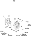
- Fig. 4 is a perspective view showing an example of respective appearance configurations of a first shaft section 17, a second shaft section 18, and a rotation drive section 19.
- the injection molding machine 100 has an accommodation space 40, and the mold unit 1 is disposed in the accommodation space 40.
- the mold unit 1 is a mold unit that enables the injection blow molding, and is configured to include the intermediate mold 10, a stationary side mold 30, and a movable side mold 20.
- the intermediate mold 10 is a rotating mold disposed between the stationary side mold 30 and the movable side mold 20.
- the intermediate mold 10 performs a mold closing operation for closing the mold and a mold opening operation for opening the mold at a position facing each of the stationary side mold 30 and the movable side mold 20.
- the mold unit 1 performs injection molding by the mold closing operation between the intermediate mold 10 and the stationary side mold 30, and performs blow molding by the mold closing operation between the intermediate mold 10 and the movable side mold 20.
- the intermediate mold 10 includes the mold section 11, a support section 12, the first shaft section 17, the second shaft section 18, and the rotation drive section 19.
- d1 in Fig. 2 indicates a length of the intermediate mold 10 according to the first embodiment in a rotation axis direction, that is, a length from a first side end portion of a shaft body 171 of the first shaft section 17 to a second side end portion of a rotational force generating portion 191 of the rotation drive section 19.
- the mold section 11 includes a rotating frame body 110 and plate groups 115 and 116.
- the rotating frame body 110 included in the mold section 11 is a metal frame body that is rotated by a rotary shaft 200.
- the rotating frame body 110 is constituted by a first side portion 111, a second side portion 112, a top side portion 113, and a bottom side portion 114, which are metal plate materials, and these are connected by bolts or the like to form one frame body.
- the plate groups 115 and 116 included in the mold section 11 are a plurality of mold plates attached to the rotating frame body 110.
- the plate group 115 is configured to be removably attached to the rotating frame body 110 via a member (not shown), and to rotate together with the rotating frame body 110 when the rotating frame body 110 rotates.
- the plate group 116 is fixed to the shaft body 171 and a shaft body 181, which do not rotate, in a state of being disposed inside the rotating frame body 110. Therefore, unlike the plate group 115, the plate group 116 has a non-rotating configuration.
- the rotating frame body 110 is described as an assembly of the first side portion 111, the second side portion 112, the top side portion 113, and the bottom side portion 114, which are metal plate materials (a boundary between the respective portions is not shown).
- the first side portion 111, the second side portion 112, the top side portion 113, and the bottom side portion 114 may be integrally formed, or may be formed by assembling a plurality of components.
- the first shaft section 17 is attached to the first side portion 111 of the rotating frame body 110 via a bearing 117 formed of a bearing or the like.
- the second shaft section 18 is attached to the second side portion 112 of the rotating frame body 110 via a bearing 118 formed of a bearing or the like.
- the plate group 115 is rotated together with the rotating frame body 110, and the plate group 115 moves while rotating between the position where the injection molding is performed by the mold closing operation with the stationary side mold 30 (see Figs. 1A and 1B ) and the position where the blow molding is performed by the mold closing operation with the movable side mold 20 (see Figs. 1A and 1B ).
- the support section 12 includes support members 13 to 16. As shown in Figs. 2 and 3 , the support member 13 included in the support section 12 is a member that supports the rotating frame body 110 via the first shaft section 17 attached to the first side portion 111 of the rotating frame body 110.
- the support member 13 is provided with a through-hole 131 formed in the rotation axis direction.
- the through-hole 131 forms a space for disposing the first shaft section 17.
- the support member 13 is provided with through-holes 132 formed in an opening and closing direction.
- the through-holes 132 are through-holes in which tie bars (not shown) that guide the mold opening and closing operations between the intermediate mold 10 and the stationary side mold 30 and the mold opening and closing operations between the intermediate mold 10 and the movable side mold 20 slide.
- the through-holes 132 are formed in the vicinity of respective end portions of the support member 13 on a top side and a bottom side in a vertical direction.
- the support member 14 included in the support section 12 is a member that supports the rotating frame body 110 via the second shaft section 18 attached to the second side portion 112 of the rotating frame body 110.
- the support member 14 is provided with a through-hole 141 formed in the rotation axis direction.
- the through-hole 141 forms a space for disposing the second shaft section 18.
- the support member 14 is provided with through-holes 142 formed in the opening and closing direction.
- the through-holes 142 are through-holes in which tie bars (not shown) that guide the mold opening and closing operations between the intermediate mold 10 and the stationary side mold 30 and the mold opening and closing operations between the intermediate mold 10 and the movable side mold 20 slide.
- the through-holes 142 are formed in the vicinity of respective end portions of the support member 14 on the top side and the bottom side in the vertical direction.
- a recessed portion 143 which is a portion recessed in a direction toward a first side of the support member 14, is formed on a second side surface 144 of the support member 14 at a position deviated from an extension line of the rotary shaft 200 toward the top side.
- the recessed portion 143 is a recessed portion that forms a space capable of accommodating at least a part of the rotation drive section 19.
- a part of a rotational force transmitting portion 192 included in the rotation drive section 19 is accommodated in the recessed portion 143.
- the recessed portion 143 may be formed at a position deviated from the extension line of the rotary shaft 200 toward the bottom side, but is preferably formed at a position deviated from the extension line of the rotary shaft 200 toward the top side as in the example of Fig. 2 . This is due to the following reasons.
- the rotation drive section 19 is disposed on the bottom side with respect to the extension line of the rotary shaft 200.
- a pipe which will be described below, is disposed on a side where the rotation drive section 19 is not disposed, that is, the top side with respect to the extension line of the rotary shaft 200, or on the extension line of the rotary shaft 200.
- the support member 15 included in the support section 12 is a member disposed on the top side of the support members 13 and 14 as shown in Figs. 2 and 3 .
- the support member 15 may be detachably connected to the support members 13 and 14 by bolts or the like, or may be joined by welding or the like.
- the support member 16 included in the support section 12 is a member disposed on the bottom side of the support members 13 and 14, and positions the support member 13 and the support member 14.
- the support member 16 may be detachably fixed to the support member 13 and the support member 14 by bolts or the like, or may be joined by welding or the like.
- the support members 13 to 16 may be integrally formed.
- the first shaft section 17 includes a shaft body 171, a first fixing member 172, and a second fixing member 173.
- the shaft body 171 is a member that allows the rotating frame body 110 to be rotated by the rotary shaft 200 in a state of being attached to the first side portion 111 via the bearing 117 of the rotating frame body 110.
- a hollow portion 201 that allows the pipe through which the fluid (liquid or gas) such as a refrigerant passes to be disposed is formed.
- An inlet/outlet port 211 and an inlet/outlet port 212 for leading the pipe disposed in the hollow portion 201 to an outside are respectively formed in the first side end portion and a second side end portion of the shaft body 171.
- the first fixing member 172 is a member that fixes the shaft body 171 in a state of penetrating the second fixing member 173, and is joined to the shaft body 171 and the second fixing member 173 by welding or the like.
- the second fixing member 173 is fixed to a first side surface 133 of the support member 13 by a bolt or the like.
- the second shaft section 18 includes the shaft body 181, a first fixing member 182, a second fixing member 183, and a manifold 184.
- the shaft body 181 is a member that allows the rotating frame body 110 to be rotated by the rotary shaft 200 in a state of being attached to the second side portion 112 via the bearing 118 of the rotating frame body 110.
- a hollow portion 202 that allows the pipe through which the fluid (liquid or gas) such as a refrigerant passes to be disposed is formed.
- An inlet/outlet port 221 and an inlet/outlet port 222 for leading the pipe disposed in the hollow portion 202 to the outside are respectively formed in a first side end portion and a second side end portion of the shaft body 181.
- the first fixing member 182 is a member that fixes the shaft body 181 in a state of penetrating the second fixing member 183, and is joined to the shaft body 181 and the second fixing member 183 by welding or the like.
- the second fixing member 183 is fixed to the second side surface 144 of the support member 14 by a bolt or the like.
- the manifold 184 is a box-shaped metal member for collecting or branching out pipes disposed in the hollow portion 202 of the shaft body 181 to lead the pipes to an outside of the intermediate mold 10.
- the manifold 184 is disposed to cover the inlet/outlet port 222 of the second side end portion of the shaft body 181 penetrating the second fixing member 183.
- the manifold 184 is provided with a plurality of through-holes 189 that allow the pipes that are led from the inlet/outlet port 222 of the second side end portion of the shaft body 181 to be disposed.
- the rotation drive section 19 includes the rotational force generating portion 191 that generates a rotational force and a rotational force transmitting portion 192 that transmits the rotational force generated by the rotational force generating portion 191 to the rotating frame body 110, and rotates the rotating frame body 110.
- the rotational force generating portion 191 is configured to include a motor or the like.
- the rotational force transmitting portion 192 is configured to include, for example, a gear box including a plurality of gears, shafts, bearings, and the like.
- the rotational force of the rotational force generating portion 191 is transmitted to the second side portion 112 of the rotating frame body 110 by the rotational force transmitting portion 192 serving as a rotational force transmitting mechanism to rotate the rotating frame body 110.
- a part of the rotational force transmitting portion 192 is accommodated in the recessed portion 143 of the support member 14, and the other part is disposed to be exposed from the recessed portion 143 to the second side.
- Fig. 5 is a perspective view showing a form when the second shaft section 18 and the rotation drive section 19 are viewed from the bottom side toward the top side in the vertical direction.
- the hollow portion 202 that allows the pipe or the electrical wire to be disposed is formed in the shaft body 181 of the second shaft section 18.
- the pipe or the electrical wire passing through the hollow portion 202 is disposed to be led to the outside of the intermediate mold 10 via the inlet/outlet port 222 of the second side end portion of the shaft body 181 and the manifold 184.
- Fig. 5 shows, as an example, a form in which the pipe 300 is led to the outside of the intermediate mold 10 via the manifold 184.
- the plurality of through-holes 189 are provided in each of a second side surface 185 in the rotation axis direction, a third side surface 186 in the opening and closing direction, a fourth side surface 187 in the opening and closing direction, and a bottom side surface 188 in the vertical direction in the manifold 184.
- four through-holes 189 are provided in the bottom side surface 188 of the manifold 184 in the vertical direction, and a pipe 300 is disposed in each of three through-holes 189. All of the pipes 300 extend toward the bottom side.
- a form of the disposition of the through-holes 189 of the manifold 184 and the pipes 300 shown in Fig. 5 is merely an example.
- Fig. 6 is a cross-sectional view showing an example of a configuration of an intermediate mold of a mold unit mounted in an injection molding machine of the related art.
- Fig. 6 shows, as the intermediate mold of the related art, a specific example of an intermediate mold including a rotating frame body to which a plate group of a mold are attached, shaft bodies respectively attached to a first side and a second side of the rotating frame body in a rotation axis direction via bearings, a support frame that fixes the shaft bodies, and a motor that applies a rotational force to the shaft body via a connection portion.
- a rotary shaft shown in Fig. 6 is in the same direction as the rotary shaft 200 shown in Fig. 2 described above.
- the intermediate mold of the related art is configured such that a motor and a connection portion are disposed on an extension line of a rotary shaft
- the rotation drive section 19 according to the first embodiment is configured such that a part of the rotation drive section 19 (a part of the rotational force transmitting portion 192 in the example of Fig. 2 ) is accommodated in the recessed portion 143 of the support member 14 provided at a position deviated from the extension line of the rotary shaft 200 in a radial direction of the rotary shaft 200.
- the intermediate mold, the mold unit, and the injection molding machine to which the first embodiment of the present invention is applied can take various embodiments with the following configuration.
- the intermediate mold 10 is an intermediate mold disposed between the stationary side mold 30 and the movable side mold 20 in the mold unit 1 of the injection molding machine 100, and includes: the mold section 11 that performs the mold opening and closing operations with a facing mold of the stationary side mold 30 and the movable side mold 20; the rotating frame body 110 that is rotated together with the mold section 11 by the rotary shaft 200; the support section 12 that supports both sides of the rotating frame body 110 via the shaft bodies 171 and 181; and the rotation drive section 19 that transmits a rotational force to the rotating frame body 110, in which the support section 12 accommodates at least a part of the rotation drive section 19.
- the pipe 300 can be led from a side where the rotation drive section 19 is disposed.
- the recessed portion 143 that accommodates at least a part of the rotation drive section 19 may be formed in the support member 14 of the support section 12.
- the recessed portion 143 may be formed at a position deviated from the extension line of the rotary shaft 200 in a radial direction of the rotary shaft 200.
- the recessed portion 143 may be formed at a position deviated from the extension line of the rotary shaft 200 toward the top side in the vertical direction.
- the pipe 300 can be extended to the bottom side where the rotation drive section 19 is not disposed.
- the fluid leaks from the pipe 300, it is possible to reduce a probability of the fluid leaking toward the top side due to the relationship between the path and sagging of the pipe 300 can be reduced.
- the rotational force transmitting portion 192 that transmits a rotational force to the rotating frame body 110 in the rotation drive section 19 may be accommodated in the recessed portion 143.
- the rotational force transmitting mechanism may be a gear mechanism that interlocks a plurality of gears.
- a size of the rotational force transmitting mechanism can be reduced compared to a case where the rotational force transmitting mechanism is a belt mechanism instead of the gear mechanism.
- the space formed by the recessed portion 143 can be reduced (a recess of the support member 14 can be reduced). Therefore, strength of the support member 14 in which the recessed portion 143 is formed can be guaranteed.
- the shaft bodies may include a hollow portion (for example, the hollow portion 202) that allows the pipe 300 through which a fluid passes to be disposed.
- the pipe 300 is disposed in the hollow portion of the non-rotating shaft body, a pipe group can be accommodated inside the intermediate mold 10.
- the intermediate mold 10 can be accommodated in the accommodation space 40 in a compact manner.
- both end portions of the hollow portion may form the inlet/outlet ports (for example, the inlet/outlet ports 221 and 222) through which the pipe 300 can enter and exit in the rotation axis direction of the shaft bodies (for example, the shaft body 181).
- the pipe can be disposed in the non-rotating shaft body 181.
- shaft bodies 171 and 181 may be respectively attached to both sides of the rotating frame body 110 in the rotation axis direction via the bearings, and the rotation drive section 19 and the pipe 300 may be disposed in the shaft body (for example, the shaft body 181) attached to one of the shaft bodies 171 and 181.
- the pipe 300 can be disposed in the shaft body 181 from the same side as the rotation drive section 19.
- the present invention provides the mold unit 1 of the injection molding machine 100, in which the intermediate mold 10 disposed between the stationary side mold 30 and the movable side mold 20 includes the mold section 11 that performs the mold opening and closing operations with a facing mold of the stationary side mold 30 and the movable side mold 20, the rotating frame body 110 that is rotated together with the mold section 11 by the rotary shaft 200, the support section 12 that supports both sides of the rotating frame body 110 via the shaft bodies 171 and 181, and the rotation drive section 19 that transmits a rotational force to the rotating frame body 110, and the support section 12 accommodates at least a part of the rotation drive section 19.
- the present invention provides the injection molding machine 100 in which the mold unit 1 including the stationary side mold 30, the movable side mold 20, and the intermediate mold 10 disposed between the stationary side mold 30 and the movable side mold 20 is mounted, in which the intermediate mold 10 includes the mold section 11 that performs the mold opening and closing operations with a facing mold of the stationary side mold 30 and the movable side mold 20, the rotating frame body 110 that is rotated together with the mold section 11 by the rotary shaft 200, the support section 12 that supports both sides of the rotating frame body 110 via the shaft bodies 171 and 181, and the rotation drive section 19 that transmits a rotational force to the rotating frame body 110, and the support section 12 accommodates at least a part of the rotation drive section 19.
- Fig. 7 is a cross-sectional view showing an example of a configuration of an intermediate mold 50 of a mold unit according to a second embodiment mounted in the injection molding machine 100 of Figs. 1A and 1B .
- a back side of the drawing refers to a third side in the opening and closing direction of Figs. 1A and 1B
- a front side of the drawing refers to a fourth side in the opening and closing direction of Figs. 1A and 1B .
- the intermediate mold 50 includes a mold section 51, a support section 52, a first shaft section 57, a second shaft section 58, and a rotation drive section 59.
- the mold section 51 includes a rotating frame body 510 which is a metal frame body that is rotated by a rotary shaft 600.
- the support section 52 includes support members 53 to 56.
- the support member 54 in the support section 52 is a member that supports the mold section 51 via the second shaft section 58 attached to a second side of the mold section 51.
- a recessed portion 543 is formed at a position deviated from an extension line of the rotary shaft 600 toward the top side on a second side of the support member 54.
- the recessed portion 543 is a recessed portion that forms a space capable of accommodating at least a part of the rotation drive section 59.
- the rotation drive section 59 includes a rotational force generating portion 591 that generates a rotational force and a rotational force transmitting portion 592 that transmits the rotational force generated by the rotational force generating portion 591 to the rotating frame body 510, and rotates the rotating frame body 510.
- a part of the rotational force transmitting portion 592 is accommodated in the recessed portion 543, and the remaining part of the rotational force transmitting portion 592 includes a portion disposed to protrude from the recessed portion 543 toward the second side and a portion disposed on the extension line of the rotary shaft 600 together with the rotational force generating portion 591.
- the rotational force of the rotational force generating portion 591 is transmitted to the rotating frame body 510 via the rotational force transmitting portion 592 serving as a rotational force transmitting mechanism to rotate the mold section 51 including the rotating frame body 510.
- the rotational force of the rotational force generating portion 591 disposed on the extension line of the rotary shaft 600 is transmitted to the rotating frame body 510 via the portion disposed on the extension line of the rotary shaft 600, the portion disposed to protrude from the recessed portion 543 toward the second side, and the part accommodated in the recessed portion 543 in the rotational force transmitting portion 592 to rotate the mold section 51.
- the intermediate mold of the related art is configured such that the motor and the connection portion are disposed on the extension line of the rotary shaft
- the rotation drive section 59 according to the second embodiment is configured such that although the rotational force generating portion 591 is disposed on the extension line of the rotary shaft 600, a part of the rotational force transmitting portion 592 is accommodated in the recessed portion 543 of the support member 54 provided at a position deviated from the extension line of the rotary shaft 600 in a radial direction of the rotary shaft 600.
- the intermediate mold, the mold unit, and the injection molding machine to which the second embodiment of the present invention is applied can take various embodiments with the following configuration.
- the intermediate mold 50 is an intermediate mold disposed between the stationary side mold 30 and the movable side mold 20 in the mold unit 1 of the injection molding machine 100, and includes: the mold section 51 that performs the mold opening and closing operations with a facing mold of the stationary side mold 30 and the movable side mold 20; the rotating frame body that is rotated together with the mold section 51 by the rotary shaft 600; the support section 52 that supports both sides of the rotating frame body via the shaft bodies 571 and 581; and the rotation drive section 59 that transmits a rotational force to the rotating frame body 510, in which the support section 52 accommodates at least a part of the rotation drive section 59.
- a part of the rotation drive section 59 may be disposed on the extension line of the rotary shaft 600.
- a part of the rotation drive section 59 can be disposed on the extension line of the rotary shaft 600, and the remaining part can be disposed at a position deviated from the extension line of the rotary shaft 600.
- a compact size of the mold unit 1 including the intermediate mold 50 in the rotation axis direction can be achieved compared to a case where an entirety of the rotation drive section 59 is disposed on the extension line of the rotary shaft 600.
- the pipe can be led from a side where the rotation drive section 19 is disposed.
- Fig. 8 is a cross-sectional view showing an example of a configuration of an intermediate mold 70 of a mold unit according to a third embodiment mounted in the injection molding machine 100 of Figs. 1A and 1B .
- a transverse direction of the intermediate mold 70 in Fig. 8 is the same direction as the opening and closing direction in Figs. 1A and 1B
- a back side of the drawing of Fig. 8 is the third side in the opening and closing direction in Figs. 1A and 1B
- a front side of the drawing of Fig. 8 is the fourth side in the opening and closing direction in Figs. 1A and 1B .
- the intermediate mold 70 shown in Fig. 8 includes a mold section 71, a support section 72, shaft bodies 77 and 78, and a rotation drive section 79.
- the mold section 71 includes a rotating frame body 710 and a plate group 716.
- the support section 72 includes support members 73 to 76.
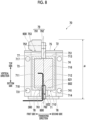
- d4 in Fig. 8 indicates a length of the intermediate mold 70 according to the third embodiment in the vertical direction.
- the rotating frame body 710 included in the mold section 71 is a metal frame body that is rotated by a rotary shaft 800.
- the rotating frame body 710 is constituted by a first side portion 711, a second side portion 712, a top side portion 713, and a bottom side portion 714, which are metal plate materials, and these are connected by bolts or the like to form one frame body.
- a plate group 716 and a plate group (not shown) are attached to the rotating frame body 710.
- the plate group 716 has a non-rotating configuration. Contrary to this, the plate group (not shown) is configured to rotate together with the rotating frame body 710 when the rotating frame body 710 rotates.
- the shaft body 77 is attached to the top side portion 713 of the rotating frame body 710 via a bearing 717 formed of a bearing or the like.
- the shaft body 78 is attached to the bottom side portion 714 of the rotating frame body 710 via a bearing 718 formed of a bearing or the like.
- the plate group (not shown) attached to the rotating frame body 710 is rotated together with the rotating frame body 710, and the plate group (not shown) moves while rotating between the position where the injection molding is performed by the mold closing operation with the stationary side mold 30 (see Figs. 1A and 1B ) and the position where the blow molding is performed by the mold closing operation with the movable side mold 20 (see Figs. 1A and 1B ).
- the support member 73 in the support section 72 is provided with through-holes 731 formed in the opening and closing direction.
- the through-holes 731 are through-holes in which tie bars (not shown) that guide the mold opening and closing operations between the intermediate mold 70 and the stationary side mold 30 and the mold opening and closing operations between the intermediate mold 70 and the movable side mold 20 slide.
- the through-holes 731 are formed in the vicinity of respective end portions of the support member 73 on the top side and the bottom side in the vertical direction.
- the support member 74 in the support section 72 is provided with through-holes 741 formed in the opening and closing direction.
- the through-holes 741 are through-holes in which tie bars (not shown) that guide the mold opening and closing operations between the intermediate mold 70 and the stationary side mold 30 and the mold opening and closing operations between the intermediate mold 70 and the movable side mold 20 slide.
- the through-holes 741 are formed in the vicinity of respective end portions of the support member 74 on the top side and the bottom side in the vertical direction.
- the support member 75 in the support section 72 is a member disposed on the top side of the support members 73 and 74.
- the support member 75 includes a fixing member 751, and fixes the shaft body 77 attached to the top side portion 713 of the rotating frame body 710 via the bearing 717.
- the support member 75 may be detachably connected to the support members 73 and 74 by bolts or the like, or may be joined by welding or the like.
- a recessed portion 753 is formed on a top side surface 752 of the support member 75. The recessed portion 753 forms a space that can accommodate a part of the rotation drive section 79.
- the support member 76 in the support section 72 is a member disposed on the bottom side of the support members 73 and 74, and positions the support member 73 and the support member 74.
- the support member 76 includes a fixing member 761, and supports the rotating frame body 710 via the shaft body 78 attached to the bottom side portion 714 of the rotating frame body 710.
- the support member 76 may be detachably fixed to the support member 73 and the support member 74 by bolts or the like, or may be joined by welding or the like.
- the support member 76 is provided with a through-hole 762 for passing the pipe 300 therethrough.
- the shaft body 77 is a member that allows the rotating frame body 710 to be rotated by the rotary shaft 800 in a state of being attached to the top side portion 713 of the rotating frame body 710 via the bearing 717.
- the shaft body 77 is fixed to the support section 72 by the fixing member 751 of the support member 75 of the support section 72.
- the shaft body 78 is a member that allows the rotating frame body 710 to be rotated by the rotary shaft 800 in a state of being attached to the bottom side portion 714 of the rotating frame body 710 via the bearing 718.
- the shaft body 78 is fixed to the support member 76 by the fixing member 761 of the support member 76 of the support section 72.
- a hollow portion 802 that allows the pipe to be disposed, and inlet/outlet ports 821 and 822 for the pipe are formed in the shaft body 78.
- the pipe 300 disposed in the hollow portion 802 is disposed to be led to an outside of the intermediate mold 70 via the inlet/outlet port 822 formed at a bottom side end portion of the shaft body 78 and via the through-hole 762 of the support member 76.
- the pipe 300 that is led to the outside of the intermediate mold 70 is connected to various devices (for example, a device that controls circulation of a refrigerant) included in the injection molding machine 100.
- the rotation drive section 79 includes a rotational force generating portion 791 that generates a rotational force and a rotational force transmitting portion 792 that transmits the rotational force generated by the rotational force generating portion 791 to the rotating frame body 710, and rotates the rotating frame body 710.
- the rotational force generating portion 791 is configured to include a motor or the like.
- the rotational force transmitting portion 792 is configured to include a gearbox or the like.
- the rotational force of the rotational force generating portion 791 is transmitted to the rotating frame body 710 via the rotational force transmitting portion 792 serving as a rotational force transmitting mechanism to rotate the rotating frame body 710.
- the rotational force generating portion 791 is configured to include a motor or the like.
- the rotational force transmitting portion 792 is configured to include a gearbox or the like.
- the rotational force of the rotational force generating portion 791 is transmitted to the rotating frame body 710 by the rotational force transmitting portion 792 serving as a rotational force transmitting mechanism to rotate the rotating frame body 710. That is, the rotational force transmitting portion 792 rotates the rotating frame body 710 by converting a rotation direction of a rotary shaft 900 of the rotational force generating portion 791 into a rotation direction of the rotary shaft 800.
- the rotational force generating portion 791 is disposed at a position deviated from the rotary shaft 800 on the top side surface 752 of the support member 75 toward the first side, and the rotational force transmitting portion 792 is disposed on an extension line of the rotary shaft 800. Specifically, the rotational force generating portion 791 is disposed in a state where a part thereof is accommodated in the recessed portion 753 formed on the top side surface 752 of the support member 75.
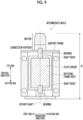
- Fig. 9 is a cross-sectional view showing an example of a configuration of an intermediate mold of a mold unit mounted in an injection molding machine of the related art.
- the intermediate mold of the related art shown in Fig. 9 includes a rotating frame body to which a plate group of a mold are attached, shaft bodies respectively attached to a top side and a bottom side of the rotating frame body via bearings (not shown), a support frame that fixes the shaft bodies, and a motor that applies a rotational force to the rotating frame body via a connection portion.
- the rotating frame body is rotated together with a plate group (not shown) by a rotary shaft shown in Fig. 9 .
- the rotary shaft shown in Fig. 9 is in the same direction as the rotary shaft 800 shown in Fig. 8 described above.
- the rotational force generating portion 791 is disposed at a position deviated from the extension line of the rotary shaft 800 in a radial direction of the rotary shaft 800, and a part of the rotational force generating portion 791 is accommodated in the recessed portion 753 of the support member 75. Accordingly, the length d4 of the intermediate mold 70 in the vertical direction is shorter than the length d5 of the intermediate mold of the related art in the rotation axis direction.
- the intermediate mold, the mold unit, and the injection molding machine to which the third embodiment of the present invention is applied can take various embodiments with the following configuration.
- the intermediate mold 70 is an intermediate mold disposed between the stationary side mold 30 and the movable side mold 20 in the mold unit 1 of the injection molding machine 100, and includes: the mold section 71 that performs the mold opening and closing operations with a facing mold of the stationary side mold 30 and the movable side mold 20; the rotating frame body 710 that is rotated together with the mold section 71 by the rotary shaft 800; the support section 72 that supports both sides of the rotating frame body 710 via the shaft bodies 77 and 78; and the rotation drive section 79 that transmits a rotational force to the rotating frame body 710, in which the support section 72 accommodates at least a part of the rotation drive section 79.
- the shaft bodies 77 and 78 may be respectively attached to both sides of the rotating frame body 710 in the vertical direction, and the support section 72 may support a top side and a bottom side of the rotating frame body 710 via the shaft bodies 77 and 78.
- the rotation drive section 79 may be connected to the top side of the rotating frame body 710, and the pipe 300 may be disposed in the shaft body 78 attached to the bottom side of the rotating frame body 710.
- the pipe can be extended to the bottom side where the rotation drive section 79 is not disposed.
- a probability of the fluid leaking toward the top side due to a relationship with a path and sagging of the pipe can be reduced.
- a configuration is adopted in which a part of the rotational force transmitting portion of the rotation drive section is accommodated in the recessed portion of the support member.
- the present invention is not limited thereto.
- An entirety of the rotational force transmitting portion may be accommodated in the recessed portion of the support member.
- a part or an entirety of the rotational force generating portion may be accommodated in the recessed portion of the support member.
- the recessed portion 753 formed in the support section 72 according to the third embodiment shown in Fig. 8 described above is not deep enough to accommodate an entirety of the rotational force generating portion 791.
- a part or the entirety of the rotational force generating portion 791 can be accommodated in the recessed portion.
- a gear mechanism including a gear box consisting of a plurality of gears is adopted as the rotational force transmitting mechanism that transmits the rotational force of the rotational force generating portion to the shaft body.
- the present invention is not limited thereto.
- a mechanism hereinafter, referred to as a "belt mechanism” that is configured to include one or more belts and one or more pulleys that are disk-shaped members for transmitting a rotational force from the belt to a rotary shaft may be adopted as the rotational force transmitting mechanism.
- the gear mechanism transmits a rotational force by mechanically meshing gears or the like, whereas the belt mechanism transmits a rotational force by using a frictional force between the belt and the pulley. Therefore, the belt mechanism may cause slippage between the belt and the pulley, resulting in a transmission loss of the rotational force.
- the belt mechanism can smoothly absorb an influence of the trouble to some extent, and thus can be said to be excellent in terms of drive stability.
- the gear mechanism is superior to the belt mechanism.
- this type of belt mechanism does not have the same degree of strength as gears in a gear mechanism.
- a gear mechanism and a belt mechanism may be used in combination as the rotational force transmitting mechanism.
- the belt mechanism in a case where the belt mechanism is accommodated in the recessed portion of the support member, it is necessary to wind a belt around both a transmission side and a reception side of the rotational force. Therefore, a size of the recessed portion needs to be larger than in a case where the gear mechanism is accommodated in the recessed portion. Therefore, it is preferable that the gear mechanism is set as a portion accommodated in the recessed portion and the belt mechanism is set as a portion not accommodated in the recessed portion.
- the gear mechanism and the belt mechanism may be accommodated in one box to integrate the rotational force transmitting mechanism, or may not be accommodated in one box.
- the gear mechanism is disposed in the recessed portion 543 to achieve compactness of the intermediate mold 50, and the belt mechanism is disposed outside the recessed portion 543 to smoothly absorb an influence of a trouble that may occur in a power transmission process.
- the manifold 184 is included as a component of the second shaft section 18.
- the present invention is not limited thereto, and the manifold may be included as a component of the first shaft section 17.
- the rotation drive section is disposed on the second side in the rotation axis direction, but the present invention is not limited thereto.
- the rotation drive section may be disposed on the first side in the rotation axis direction. That is, the side on which the rotation drive section is disposed may be determined according to a position where an operation panel (not shown) of the injection molding machine 100 of Figs. 1A and 1B is disposed or an ease of work for a worker.
Landscapes
- Engineering & Computer Science (AREA)
- Mechanical Engineering (AREA)
- Manufacturing & Machinery (AREA)
- Physics & Mathematics (AREA)
- Fluid Mechanics (AREA)
- Moulds For Moulding Plastics Or The Like (AREA)
Abstract
Compactness of a mold unit (1) including an intermediate mold (10, 50, 70) is achieved. An intermediate mold (10, 50, 70) that is disposed between a stationary side mold (30) and a movable side mold (20) in a mold unit (1) of an injection molding machine (100) is an intermediate mold (10, 50, 70) disposed between the stationary side mold (30) and the movable side mold (20), and includes: a mold section (11, 51, 71) that performs mold opening and closing operations with a facing mold of the stationary side mold (30) and the movable side mold (20); a rotating frame body (110, 510, 710) that is rotated together with the mold section (11, 51, 71) by a rotary shaft (200, 600, 800); a support section (12, 52, 72) that supports both sides of the rotating frame body (110, 510, 710) via shaft bodies (171, 181, 571, 581, 77, 78); and a rotation drive section (19, 59, 79) that transmits a rotational force to the rotating frame body (110, 510, 710), in which the support section (12, 52, 72) accommodates at least a part of the rotation drive section (19, 59, 79).
Description
- The present invention relates to an intermediate mold, a mold unit, and an injection molding machine.
- As a mold unit included in an injection molding machine, there is a mold unit in which an intermediate mold is disposed between a mold on a stationary side and a mold on a movable side. In addition, as the intermediate mold, there is an intermediate mold including a rotating mold that moves while rotating between a position facing the mold on the stationary side and a position facing the mold on the movable side and alternately performs mold opening and closing operations at each position (for example,
Japanese Patent No. 4283181 - An accommodation space for accommodating the mold unit including the intermediate mold in the injection molding machine is limited in terms of size due to a relationship with a size of the injection molding machine. Therefore, there is a demand for a compact size for the mold unit including the intermediate mold. However, the intermediate mold of the related art adopts a method of connecting the rotation drive section to the rotating frame body in series. In this case, an entirety of the rotation drive section is disposed on an extension line of a rotary shaft of the rotating frame body, which inhibits compactness of a size of the mold unit.
- An object of the present invention is to achieve compactness of a mold unit including an intermediate mold.
- According to the present invention completed under the above object, there is provided an intermediate mold that is disposed between a stationary side mold and a movable side mold in a mold unit of an injection molding machine, the intermediate mold including: a mold section that performs mold opening and closing operations with a facing mold of the stationary side mold and the movable side mold; a rotating frame body that is rotated together with the mold section by a rotary shaft; a support section that supports both sides of the rotating frame body via shaft bodies; and a rotation drive section that transmits a rotational force to the rotating frame body, in which the support section accommodates at least a part of the rotation drive section.
- Here, a recessed portion that accommodates at least a part of the rotation drive section may be formed in the support section.
- In addition, the recessed portion may be formed at a position deviated from an extension line of the rotary shaft in a radial direction of the rotary shaft.
- In addition, the recessed portion may be formed at a position deviated from the extension line of the rotary shaft toward a top side in a vertical direction.
- In addition, at least a part of a rotational force transmitting mechanism that transmits the rotational force to the rotating frame body in the rotation drive section may be accommodated in the recessed portion.
- In addition, the rotational force transmitting mechanism may be a gear mechanism that interlocks a plurality of gears.
- In addition, a part of the rotation drive section may be disposed on an extension line of the rotary shaft.
- In addition, the shaft bodies may include a hollow portion that allows a pipe through which a fluid passes to be disposed.
- In addition, both end portions of the hollow portion may form inlet/outlet ports through which the pipe can enter and exit in a rotation axis direction of the shaft bodies.
- In addition, the shaft bodies may be respectively attached to both sides of the rotating frame body in the rotation axis direction via bearings, and the rotation drive section and the pipe may be disposed on a side of one of the shaft bodies.
- In addition, the shaft bodies may be respectively attached to both sides of the rotating frame body in a vertical direction via bearings, and the support section may support a top side and a bottom side of the rotating frame body via the shaft bodies.
- In addition, the rotation drive section may be connected to the top side of the rotating frame body, and a pipe through which a fluid passes may be disposed in the shaft body attached to the bottom side of the rotating frame body.
- In addition, according to the present invention, there is provided a mold unit of an injection molding machine, the mold unit including: an intermediate mold disposed between a stationary side mold and a movable side mold, in which the intermediate mold includes a mold section that performs mold opening and closing operations with a facing mold of the stationary side mold and the movable side mold, a rotating frame body that is rotated together with the mold section by a rotary shaft, a support section that supports both sides of the rotating frame body via shaft bodies, and a rotation drive section that transmits a rotational force to the rotating frame body, and the support section accommodates at least a part of the rotation drive section.
- In addition, according to the present invention, there is provided an injection molding machine including: a mold unit that includes a stationary side mold, a movable side mold, and an intermediate mold disposed between the stationary side mold and the movable side mold, the mold unit being mounted in the injection molding machine, in which the intermediate mold includes a mold section that performs mold opening and closing operations with a facing mold of the stationary side mold and the movable side mold, a rotating frame body that is rotated together with the mold section by a rotary shaft, a support section that supports both sides of the rotating frame body via shaft bodies, and a rotation drive section that transmits a rotational force to the rotating frame body, and the support section accommodates at least a part of the rotation drive section.
- According to the present invention, it is possible to achieve compactness of the mold unit including the intermediate mold.
-
-
Figs. 1A and 1B are perspective views showing an example of respective appearance configurations of a part of an injection molding machine and a part of a mold unit mounted in the injection molding machine according to a first embodiment. -
Fig. 2 is a cross-sectional view showing an example of a configuration of an intermediate mold of the mold unit. -
Fig. 3 is a perspective view showing a state after a mold section is removed from the intermediate mold. -
Fig. 4 is a perspective view showing an example of respective appearance configurations of a first shaft section, a second shaft section, and a rotation drive section. -
Fig. 5 is a perspective view showing a form when the second shaft section and the rotation drive section are viewed from a bottom side toward a top side in a vertical direction. -
Fig. 6 is a cross-sectional view showing an example of a configuration of an intermediate mold of a mold unit mounted in an injection molding machine of the related art. -
Fig. 7 is a cross-sectional view showing an example of a configuration of an intermediate mold of a mold unit according to a second embodiment mounted in the injection molding machine ofFigs. 1A and 1B . -
Fig. 8 is a cross-sectional view showing an example of a configuration of an intermediate mold of a mold unit according to a third embodiment mounted in the injection molding machine ofFigs. 1A and 1B . -
Fig. 9 is a cross-sectional view showing an example of a configuration of an intermediate mold of a mold unit mounted in an injection molding machine of the related art. - Hereinafter, embodiments of the present invention will be described in detail with reference to the accompanying drawings.
-
Figs. 1A and 1B are perspective views showing an example of respective appearance configurations of a part of aninjection molding machine 100 and a part of amold unit 1 mounted in theinjection molding machine 100 according to a first embodiment. -
Fig. 2 is a cross-sectional view showing an example of a configuration of anintermediate mold 10 of themold unit 1. -
Fig. 3 is a perspective view showing a state after amold section 11 is removed from theintermediate mold 10. -
Fig. 4 is a perspective view showing an example of respective appearance configurations of afirst shaft section 17, asecond shaft section 18, and arotation drive section 19. - The
injection molding machine 100 shown inFigs. 1A and 1B is a molding machine used for injection blow molding. The injection blow molding refers to a molding method in which injection molding and blow molding are performed in two stages. In the injection blow molding, first, a preform, which serves as a prototype for a product, is molded in the injection molding. Then, in the blow molding, air is fed into an inside of the preform to expand the preform, thereby molding a product. - The
injection molding machine 100 has anaccommodation space 40, and themold unit 1 is disposed in theaccommodation space 40. Themold unit 1 is a mold unit that enables the injection blow molding, and is configured to include theintermediate mold 10, astationary side mold 30, and amovable side mold 20. Theintermediate mold 10 is a rotating mold disposed between thestationary side mold 30 and themovable side mold 20. Theintermediate mold 10 performs a mold closing operation for closing the mold and a mold opening operation for opening the mold at a position facing each of thestationary side mold 30 and themovable side mold 20. Themold unit 1 performs injection molding by the mold closing operation between theintermediate mold 10 and thestationary side mold 30, and performs blow molding by the mold closing operation between theintermediate mold 10 and themovable side mold 20. - As shown in
Figs. 1B and2 , theintermediate mold 10 includes themold section 11, asupport section 12, thefirst shaft section 17, thesecond shaft section 18, and therotation drive section 19. In addition, d1 inFig. 2 indicates a length of theintermediate mold 10 according to the first embodiment in a rotation axis direction, that is, a length from a first side end portion of ashaft body 171 of thefirst shaft section 17 to a second side end portion of a rotationalforce generating portion 191 of therotation drive section 19. - The
mold section 11 includes a rotatingframe body 110 andplate groups frame body 110 included in themold section 11 is a metal frame body that is rotated by arotary shaft 200. The rotatingframe body 110 is constituted by afirst side portion 111, asecond side portion 112, atop side portion 113, and abottom side portion 114, which are metal plate materials, and these are connected by bolts or the like to form one frame body. Theplate groups mold section 11 are a plurality of mold plates attached to therotating frame body 110. Theplate group 115 is configured to be removably attached to therotating frame body 110 via a member (not shown), and to rotate together with therotating frame body 110 when therotating frame body 110 rotates. Contrary to this, theplate group 116 is fixed to theshaft body 171 and ashaft body 181, which do not rotate, in a state of being disposed inside therotating frame body 110. Therefore, unlike theplate group 115, theplate group 116 has a non-rotating configuration. - In the present embodiment, the
rotating frame body 110 is described as an assembly of thefirst side portion 111, thesecond side portion 112, thetop side portion 113, and thebottom side portion 114, which are metal plate materials (a boundary between the respective portions is not shown). However, thefirst side portion 111, thesecond side portion 112, thetop side portion 113, and thebottom side portion 114 may be integrally formed, or may be formed by assembling a plurality of components. - The
first shaft section 17 is attached to thefirst side portion 111 of therotating frame body 110 via abearing 117 formed of a bearing or the like. Thesecond shaft section 18 is attached to thesecond side portion 112 of therotating frame body 110 via abearing 118 formed of a bearing or the like. In themold section 11, when therotating frame body 110 is rotated by therotary shaft 200, theplate group 115 is rotated together with therotating frame body 110, and theplate group 115 moves while rotating between the position where the injection molding is performed by the mold closing operation with the stationary side mold 30 (seeFigs. 1A and 1B ) and the position where the blow molding is performed by the mold closing operation with the movable side mold 20 (seeFigs. 1A and 1B ). - The
support section 12 includessupport members 13 to 16. As shown inFigs. 2 and3 , thesupport member 13 included in thesupport section 12 is a member that supports therotating frame body 110 via thefirst shaft section 17 attached to thefirst side portion 111 of therotating frame body 110. Thesupport member 13 is provided with a through-hole 131 formed in the rotation axis direction. The through-hole 131 forms a space for disposing thefirst shaft section 17. In addition, thesupport member 13 is provided with through-holes 132 formed in an opening and closing direction. The through-holes 132 are through-holes in which tie bars (not shown) that guide the mold opening and closing operations between theintermediate mold 10 and thestationary side mold 30 and the mold opening and closing operations between theintermediate mold 10 and themovable side mold 20 slide. The through-holes 132 are formed in the vicinity of respective end portions of thesupport member 13 on a top side and a bottom side in a vertical direction. - As shown in
Figs. 2 and3 , thesupport member 14 included in thesupport section 12 is a member that supports therotating frame body 110 via thesecond shaft section 18 attached to thesecond side portion 112 of therotating frame body 110. Thesupport member 14 is provided with a through-hole 141 formed in the rotation axis direction. The through-hole 141 forms a space for disposing thesecond shaft section 18. In addition, thesupport member 14 is provided with through-holes 142 formed in the opening and closing direction. The through-holes 142 are through-holes in which tie bars (not shown) that guide the mold opening and closing operations between theintermediate mold 10 and thestationary side mold 30 and the mold opening and closing operations between theintermediate mold 10 and themovable side mold 20 slide. The through-holes 142 are formed in the vicinity of respective end portions of thesupport member 14 on the top side and the bottom side in the vertical direction. - In addition, as shown in
Fig. 2 , a recessedportion 143, which is a portion recessed in a direction toward a first side of thesupport member 14, is formed on asecond side surface 144 of thesupport member 14 at a position deviated from an extension line of therotary shaft 200 toward the top side. The recessedportion 143 is a recessed portion that forms a space capable of accommodating at least a part of therotation drive section 19. In an example ofFig. 2 , a part of a rotationalforce transmitting portion 192 included in therotation drive section 19 is accommodated in the recessedportion 143. The recessedportion 143 may be formed at a position deviated from the extension line of therotary shaft 200 toward the bottom side, but is preferably formed at a position deviated from the extension line of therotary shaft 200 toward the top side as in the example ofFig. 2 . This is due to the following reasons. - That is, in a case where the recessed
portion 143 is formed at a position deviated from the extension line of therotary shaft 200 toward the bottom side, therotation drive section 19 is disposed on the bottom side with respect to the extension line of therotary shaft 200. In this case, a pipe, which will be described below, is disposed on a side where therotation drive section 19 is not disposed, that is, the top side with respect to the extension line of therotary shaft 200, or on the extension line of therotary shaft 200. However, compared to a case where the pipe is disposed on the bottom side with respect to the extension line of therotary shaft 200, when a fluid leaks from the pipe, a probability of the fluid leaking toward the top side due to a relationship with a path and sagging of the pipe increases. - The
support member 15 included in thesupport section 12 is a member disposed on the top side of thesupport members Figs. 2 and3 . Thesupport member 15 may be detachably connected to thesupport members Figs. 1A to 3 , thesupport member 16 included in thesupport section 12 is a member disposed on the bottom side of thesupport members support member 13 and thesupport member 14. Thesupport member 16 may be detachably fixed to thesupport member 13 and thesupport member 14 by bolts or the like, or may be joined by welding or the like. In addition, thesupport members 13 to 16 may be integrally formed. - As shown in
Figs. 2 to 4 , thefirst shaft section 17 includes ashaft body 171, a first fixingmember 172, and asecond fixing member 173. Theshaft body 171 is a member that allows therotating frame body 110 to be rotated by therotary shaft 200 in a state of being attached to thefirst side portion 111 via the bearing 117 of therotating frame body 110. In theshaft body 171, ahollow portion 201 that allows the pipe through which the fluid (liquid or gas) such as a refrigerant passes to be disposed is formed. An inlet/outlet port 211 and an inlet/outlet port 212 for leading the pipe disposed in thehollow portion 201 to an outside are respectively formed in the first side end portion and a second side end portion of theshaft body 171. - The
first fixing member 172 is a member that fixes theshaft body 171 in a state of penetrating the second fixingmember 173, and is joined to theshaft body 171 and the second fixingmember 173 by welding or the like. Thesecond fixing member 173 is fixed to afirst side surface 133 of thesupport member 13 by a bolt or the like. - As shown in
Figs. 2 to 4 , thesecond shaft section 18 includes theshaft body 181, a first fixingmember 182, asecond fixing member 183, and amanifold 184. Theshaft body 181 is a member that allows therotating frame body 110 to be rotated by therotary shaft 200 in a state of being attached to thesecond side portion 112 via the bearing 118 of therotating frame body 110. In theshaft body 181, ahollow portion 202 that allows the pipe through which the fluid (liquid or gas) such as a refrigerant passes to be disposed is formed. An inlet/outlet port 221 and an inlet/outlet port 222 for leading the pipe disposed in thehollow portion 202 to the outside are respectively formed in a first side end portion and a second side end portion of theshaft body 181. Thefirst fixing member 182 is a member that fixes theshaft body 181 in a state of penetrating the second fixingmember 183, and is joined to theshaft body 181 and the second fixingmember 183 by welding or the like. Thesecond fixing member 183 is fixed to thesecond side surface 144 of thesupport member 14 by a bolt or the like. - As shown in
Figs. 2 to 4 , the manifold 184 is a box-shaped metal member for collecting or branching out pipes disposed in thehollow portion 202 of theshaft body 181 to lead the pipes to an outside of theintermediate mold 10. The manifold 184 is disposed to cover the inlet/outlet port 222 of the second side end portion of theshaft body 181 penetrating the second fixingmember 183. As shown inFigs. 3 and4 , the manifold 184 is provided with a plurality of through-holes 189 that allow the pipes that are led from the inlet/outlet port 222 of the second side end portion of theshaft body 181 to be disposed. - As shown in
Figs. 2 to 4 , therotation drive section 19 includes the rotationalforce generating portion 191 that generates a rotational force and a rotationalforce transmitting portion 192 that transmits the rotational force generated by the rotationalforce generating portion 191 to therotating frame body 110, and rotates therotating frame body 110. The rotationalforce generating portion 191 is configured to include a motor or the like. The rotationalforce transmitting portion 192 is configured to include, for example, a gear box including a plurality of gears, shafts, bearings, and the like. In therotation drive section 19, the rotational force of the rotationalforce generating portion 191 is transmitted to thesecond side portion 112 of therotating frame body 110 by the rotationalforce transmitting portion 192 serving as a rotational force transmitting mechanism to rotate therotating frame body 110. In therotation drive section 19 according to the first embodiment, a part of the rotationalforce transmitting portion 192 is accommodated in the recessedportion 143 of thesupport member 14, and the other part is disposed to be exposed from the recessedportion 143 to the second side. -
Fig. 5 is a perspective view showing a form when thesecond shaft section 18 and therotation drive section 19 are viewed from the bottom side toward the top side in the vertical direction. - As shown in
Fig. 2 described above, thehollow portion 202 that allows the pipe or the electrical wire to be disposed is formed in theshaft body 181 of thesecond shaft section 18. The pipe or the electrical wire passing through thehollow portion 202 is disposed to be led to the outside of theintermediate mold 10 via the inlet/outlet port 222 of the second side end portion of theshaft body 181 and themanifold 184.Fig. 5 shows, as an example, a form in which thepipe 300 is led to the outside of theintermediate mold 10 via themanifold 184. - In the example of
Fig. 5 , the plurality of through-holes 189 are provided in each of asecond side surface 185 in the rotation axis direction, athird side surface 186 in the opening and closing direction, afourth side surface 187 in the opening and closing direction, and abottom side surface 188 in the vertical direction in themanifold 184. Specifically, four through-holes 189 are provided in thebottom side surface 188 of the manifold 184 in the vertical direction, and apipe 300 is disposed in each of three through-holes 189. All of thepipes 300 extend toward the bottom side. In addition, a form of the disposition of the through-holes 189 of the manifold 184 and thepipes 300 shown inFig. 5 is merely an example. -
Fig. 6 is a cross-sectional view showing an example of a configuration of an intermediate mold of a mold unit mounted in an injection molding machine of the related art. -
Fig. 6 shows, as the intermediate mold of the related art, a specific example of an intermediate mold including a rotating frame body to which a plate group of a mold are attached, shaft bodies respectively attached to a first side and a second side of the rotating frame body in a rotation axis direction via bearings, a support frame that fixes the shaft bodies, and a motor that applies a rotational force to the shaft body via a connection portion. A rotary shaft shown inFig. 6 is in the same direction as therotary shaft 200 shown inFig. 2 described above. - When a length d2 of an intermediate mold of the related art in a rotation axis direction shown in
Fig. 6 is compared with a length d1 of theintermediate mold 10 according to the first embodiment in the rotation axis direction shown inFig. 2 , d2 > d1 is satisfied. - This is because the intermediate mold of the related art is configured such that a motor and a connection portion are disposed on an extension line of a rotary shaft, whereas the
rotation drive section 19 according to the first embodiment is configured such that a part of the rotation drive section 19 (a part of the rotationalforce transmitting portion 192 in the example ofFig. 2 ) is accommodated in the recessedportion 143 of thesupport member 14 provided at a position deviated from the extension line of therotary shaft 200 in a radial direction of therotary shaft 200. - In summary, the intermediate mold, the mold unit, and the injection molding machine to which the first embodiment of the present invention is applied can take various embodiments with the following configuration.
- That is, the
intermediate mold 10 according to the first embodiment is an intermediate mold disposed between thestationary side mold 30 and themovable side mold 20 in themold unit 1 of theinjection molding machine 100, and includes: themold section 11 that performs the mold opening and closing operations with a facing mold of thestationary side mold 30 and themovable side mold 20; therotating frame body 110 that is rotated together with themold section 11 by therotary shaft 200; thesupport section 12 that supports both sides of therotating frame body 110 via theshaft bodies rotation drive section 19 that transmits a rotational force to therotating frame body 110, in which thesupport section 12 accommodates at least a part of therotation drive section 19. - Accordingly, since a part of the
rotation drive section 19 is accommodated in thesupport section 12, a compact size of themold unit 1 including theintermediate mold 10 in the rotation axis direction can be achieved compared to a case where a part of therotation drive section 19 is not accommodated in thesupport section 12. Furthermore, thepipe 300 can be led from a side where therotation drive section 19 is disposed. - Here, the recessed
portion 143 that accommodates at least a part of therotation drive section 19 may be formed in thesupport member 14 of thesupport section 12. - Accordingly, since at least a part of the
rotation drive section 19 is accommodated in the recessedportion 143 of thesupport member 14, a compact size of themold unit 1 including theintermediate mold 10 in the rotation axis direction can be achieved compared to a case where at least a part of therotation drive section 19 is not accommodated in the recessedportion 143 of thesupport section 12. - In addition, the recessed
portion 143 may be formed at a position deviated from the extension line of therotary shaft 200 in a radial direction of therotary shaft 200. - Accordingly, since at least a part of the
rotation drive section 19 is accommodated in the recessedportion 143 formed at a position deviated from the extension line of therotary shaft 200 in the radial direction of therotary shaft 200, at least a part of therotation drive section 19 is disposed in parallel with theshaft body 181, instead of being disposed in series with theshaft body 181. As a result, a compact size of themold unit 1 including theintermediate mold 10 in the rotation axis direction can be achieved compared to a case where at least a part of therotation drive section 19 is disposed in series with theshaft body 181. - In addition, the recessed
portion 143 may be formed at a position deviated from the extension line of therotary shaft 200 toward the top side in the vertical direction. - Accordingly, since at least a part of the
rotation drive section 19 is disposed on the top side with respect to theshaft body 181, thepipe 300 can be extended to the bottom side where therotation drive section 19 is not disposed. As a result, when the fluid leaks from thepipe 300, it is possible to reduce a probability of the fluid leaking toward the top side due to the relationship between the path and sagging of thepipe 300 can be reduced. - In addition, at least a part of the rotational
force transmitting portion 192 that transmits a rotational force to therotating frame body 110 in therotation drive section 19 may be accommodated in the recessedportion 143. - Accordingly, since at least a part of the rotational
force transmitting portion 192 is accommodated in the recessedportion 143, at least a part of the rotationalforce transmitting portion 192 is disposed in parallel with therotary shaft 200, instead of being disposed in series with therotary shaft 200. As a result, a compact size of themold unit 1 including theintermediate mold 10 in the rotation axis direction can be achieved compared to a case where at least a part of the rotationalforce transmitting portion 192 is disposed in series with therotary shaft 200. - In addition, the rotational force transmitting mechanism may be a gear mechanism that interlocks a plurality of gears.
- Accordingly, for example, a size of the rotational force transmitting mechanism can be reduced compared to a case where the rotational force transmitting mechanism is a belt mechanism instead of the gear mechanism. As a result, the space formed by the recessed
portion 143 can be reduced (a recess of thesupport member 14 can be reduced). Therefore, strength of thesupport member 14 in which the recessedportion 143 is formed can be guaranteed. - In addition, the shaft bodies (for example, the shaft body 181) may include a hollow portion (for example, the hollow portion 202) that allows the
pipe 300 through which a fluid passes to be disposed. - Accordingly, since the
pipe 300 is disposed in the hollow portion of the non-rotating shaft body, a pipe group can be accommodated inside theintermediate mold 10. As a result, theintermediate mold 10 can be accommodated in theaccommodation space 40 in a compact manner. - In addition, both end portions of the hollow portion (for example, the hollow portion 202) may form the inlet/outlet ports (for example, the inlet/
outlet ports 221 and 222) through which thepipe 300 can enter and exit in the rotation axis direction of the shaft bodies (for example, the shaft body 181). - Accordingly, the pipe can be disposed in the
non-rotating shaft body 181. - In addition, the
shaft bodies rotating frame body 110 in the rotation axis direction via the bearings, and therotation drive section 19 and thepipe 300 may be disposed in the shaft body (for example, the shaft body 181) attached to one of theshaft bodies - Accordingly, even when the
rotation drive section 19 is connected to theshaft body 181, thepipe 300 can be disposed in theshaft body 181 from the same side as therotation drive section 19. - In addition, the present invention provides the
mold unit 1 of theinjection molding machine 100, in which theintermediate mold 10 disposed between thestationary side mold 30 and themovable side mold 20 includes themold section 11 that performs the mold opening and closing operations with a facing mold of thestationary side mold 30 and themovable side mold 20, therotating frame body 110 that is rotated together with themold section 11 by therotary shaft 200, thesupport section 12 that supports both sides of therotating frame body 110 via theshaft bodies rotation drive section 19 that transmits a rotational force to therotating frame body 110, and thesupport section 12 accommodates at least a part of therotation drive section 19. - Accordingly, since a part of the
rotation drive section 19 is accommodated in thesupport section 12, a compact size of themold unit 1 including theintermediate mold 10 in the rotation axis direction can be achieved compared to a case where a part of therotation drive section 19 is not accommodated in thesupport section 12. Furthermore, the pipe can be led from a side where therotation drive section 19 is disposed. - In addition, the present invention provides the
injection molding machine 100 in which themold unit 1 including thestationary side mold 30, themovable side mold 20, and theintermediate mold 10 disposed between thestationary side mold 30 and themovable side mold 20 is mounted, in which theintermediate mold 10 includes themold section 11 that performs the mold opening and closing operations with a facing mold of thestationary side mold 30 and themovable side mold 20, therotating frame body 110 that is rotated together with themold section 11 by therotary shaft 200, thesupport section 12 that supports both sides of therotating frame body 110 via theshaft bodies rotation drive section 19 that transmits a rotational force to therotating frame body 110, and thesupport section 12 accommodates at least a part of therotation drive section 19. - Accordingly, since a part of the
rotation drive section 19 is accommodated in thesupport section 12, a compact size of themold unit 1 including theintermediate mold 10 in the rotation axis direction can be achieved compared to a case where a part of therotation drive section 19 is not accommodated in thesupport section 12. Furthermore, the pipe can be led from a side where therotation drive section 19 is disposed. -
Fig. 7 is a cross-sectional view showing an example of a configuration of anintermediate mold 50 of a mold unit according to a second embodiment mounted in theinjection molding machine 100 ofFigs. 1A and 1B . In addition, inFig. 7 , a back side of the drawing refers to a third side in the opening and closing direction ofFigs. 1A and 1B , and a front side of the drawing refers to a fourth side in the opening and closing direction ofFigs. 1A and 1B . - As shown in
Fig. 7 , theintermediate mold 50 includes amold section 51, asupport section 52, a first shaft section 57, asecond shaft section 58, and arotation drive section 59. Themold section 51 includes arotating frame body 510 which is a metal frame body that is rotated by arotary shaft 600. - The
support section 52 includessupport members 53 to 56. Thesupport member 54 in thesupport section 52 is a member that supports themold section 51 via thesecond shaft section 58 attached to a second side of themold section 51. A recessedportion 543 is formed at a position deviated from an extension line of therotary shaft 600 toward the top side on a second side of thesupport member 54. The recessedportion 543 is a recessed portion that forms a space capable of accommodating at least a part of therotation drive section 59. - The first shaft section 57 includes a shaft body 571, a first fixing member 572, and a second fixing member 573. The
second shaft section 58 includes ashaft body 581, a first fixingmember 582, asecond fixing member 583, and amanifold 584. - As shown in
Fig. 7 , therotation drive section 59 includes a rotationalforce generating portion 591 that generates a rotational force and a rotationalforce transmitting portion 592 that transmits the rotational force generated by the rotationalforce generating portion 591 to therotating frame body 510, and rotates therotating frame body 510. In therotation drive section 59 according to the second embodiment, a part of the rotationalforce transmitting portion 592 is accommodated in the recessedportion 543, and the remaining part of the rotationalforce transmitting portion 592 includes a portion disposed to protrude from the recessedportion 543 toward the second side and a portion disposed on the extension line of therotary shaft 600 together with the rotationalforce generating portion 591. - In the
rotation drive section 59, the rotational force of the rotationalforce generating portion 591 is transmitted to therotating frame body 510 via the rotationalforce transmitting portion 592 serving as a rotational force transmitting mechanism to rotate themold section 51 including therotating frame body 510. In the example ofFig. 7 , the rotational force of the rotationalforce generating portion 591 disposed on the extension line of therotary shaft 600 is transmitted to therotating frame body 510 via the portion disposed on the extension line of therotary shaft 600, the portion disposed to protrude from the recessedportion 543 toward the second side, and the part accommodated in the recessedportion 543 in the rotationalforce transmitting portion 592 to rotate themold section 51. - In addition, the other configurations of the
mold section 51, thesupport section 52, the first shaft section 57, and thesecond shaft section 58 shown inFig. 7 are the same as the configurations of themold section 11, thesupport section 12, thefirst shaft section 17, and thesecond shaft section 18 shown inFig. 2 described above, and the description thereof will be omitted. In addition, d3 inFig. 7 indicates a length of theintermediate mold 50 according to the second embodiment in the rotation axis direction. - Here, when a length d3 of the
intermediate mold 50 according to the second embodiment in the rotation axis direction shown inFig. 7 is compared with the length d2 of the intermediate mold of the related art in the rotation axis direction shown inFig. 6 , d3 < d2 is satisfied. This is because the intermediate mold of the related art is configured such that the motor and the connection portion are disposed on the extension line of the rotary shaft, whereas therotation drive section 59 according to the second embodiment is configured such that although the rotationalforce generating portion 591 is disposed on the extension line of therotary shaft 600, a part of the rotationalforce transmitting portion 592 is accommodated in the recessedportion 543 of thesupport member 54 provided at a position deviated from the extension line of therotary shaft 600 in a radial direction of therotary shaft 600. - In summary, the intermediate mold, the mold unit, and the injection molding machine to which the second embodiment of the present invention is applied can take various embodiments with the following configuration.
- That is, the
intermediate mold 50 according to the second embodiment is an intermediate mold disposed between thestationary side mold 30 and themovable side mold 20 in themold unit 1 of theinjection molding machine 100, and includes: themold section 51 that performs the mold opening and closing operations with a facing mold of thestationary side mold 30 and themovable side mold 20; the rotating frame body that is rotated together with themold section 51 by therotary shaft 600; thesupport section 52 that supports both sides of the rotating frame body via theshaft bodies 571 and 581; and therotation drive section 59 that transmits a rotational force to therotating frame body 510, in which thesupport section 52 accommodates at least a part of therotation drive section 59. - Here, a part of the
rotation drive section 59 may be disposed on the extension line of therotary shaft 600. - Accordingly, a part of the
rotation drive section 59 can be disposed on the extension line of therotary shaft 600, and the remaining part can be disposed at a position deviated from the extension line of therotary shaft 600. As a result, a compact size of themold unit 1 including theintermediate mold 50 in the rotation axis direction can be achieved compared to a case where an entirety of therotation drive section 59 is disposed on the extension line of therotary shaft 600. Furthermore, the pipe can be led from a side where therotation drive section 19 is disposed. -
Fig. 8 is a cross-sectional view showing an example of a configuration of anintermediate mold 70 of a mold unit according to a third embodiment mounted in theinjection molding machine 100 ofFigs. 1A and 1B . In addition, a transverse direction of theintermediate mold 70 inFig. 8 is the same direction as the opening and closing direction inFigs. 1A and 1B , a back side of the drawing ofFig. 8 is the third side in the opening and closing direction inFigs. 1A and 1B , and a front side of the drawing ofFig. 8 is the fourth side in the opening and closing direction inFigs. 1A and 1B . - The
intermediate mold 70 shown inFig. 8 includes amold section 71, asupport section 72,shaft bodies rotation drive section 79. Themold section 71 includes arotating frame body 710 and aplate group 716. Thesupport section 72 includessupport members 73 to 76. In addition, d4 inFig. 8 indicates a length of theintermediate mold 70 according to the third embodiment in the vertical direction. - The
rotating frame body 710 included in themold section 71 is a metal frame body that is rotated by arotary shaft 800. Therotating frame body 710 is constituted by afirst side portion 711, asecond side portion 712, atop side portion 713, and abottom side portion 714, which are metal plate materials, and these are connected by bolts or the like to form one frame body. Aplate group 716 and a plate group (not shown) are attached to therotating frame body 710. Theplate group 716 has a non-rotating configuration. Contrary to this, the plate group (not shown) is configured to rotate together with therotating frame body 710 when therotating frame body 710 rotates. - The
shaft body 77 is attached to thetop side portion 713 of therotating frame body 710 via abearing 717 formed of a bearing or the like. Theshaft body 78 is attached to thebottom side portion 714 of therotating frame body 710 via abearing 718 formed of a bearing or the like. In themold section 71, when therotating frame body 710 is rotated by therotary shaft 800, the plate group (not shown) attached to therotating frame body 710 is rotated together with therotating frame body 710, and the plate group (not shown) moves while rotating between the position where the injection molding is performed by the mold closing operation with the stationary side mold 30 (seeFigs. 1A and 1B ) and the position where the blow molding is performed by the mold closing operation with the movable side mold 20 (seeFigs. 1A and 1B ). - The
support member 73 in thesupport section 72 is provided with through-holes 731 formed in the opening and closing direction. The through-holes 731 are through-holes in which tie bars (not shown) that guide the mold opening and closing operations between theintermediate mold 70 and thestationary side mold 30 and the mold opening and closing operations between theintermediate mold 70 and themovable side mold 20 slide. The through-holes 731 are formed in the vicinity of respective end portions of thesupport member 73 on the top side and the bottom side in the vertical direction. - The
support member 74 in thesupport section 72 is provided with through-holes 741 formed in the opening and closing direction. The through-holes 741 are through-holes in which tie bars (not shown) that guide the mold opening and closing operations between theintermediate mold 70 and thestationary side mold 30 and the mold opening and closing operations between theintermediate mold 70 and themovable side mold 20 slide. The through-holes 741 are formed in the vicinity of respective end portions of thesupport member 74 on the top side and the bottom side in the vertical direction. - The
support member 75 in thesupport section 72 is a member disposed on the top side of thesupport members support member 75 includes a fixingmember 751, and fixes theshaft body 77 attached to thetop side portion 713 of therotating frame body 710 via thebearing 717. Thesupport member 75 may be detachably connected to thesupport members portion 753 is formed on atop side surface 752 of thesupport member 75. The recessedportion 753 forms a space that can accommodate a part of therotation drive section 79. - The
support member 76 in thesupport section 72 is a member disposed on the bottom side of thesupport members support member 73 and thesupport member 74. Thesupport member 76 includes a fixingmember 761, and supports therotating frame body 710 via theshaft body 78 attached to thebottom side portion 714 of therotating frame body 710. Thesupport member 76 may be detachably fixed to thesupport member 73 and thesupport member 74 by bolts or the like, or may be joined by welding or the like. Thesupport member 76 is provided with a through-hole 762 for passing thepipe 300 therethrough. - The
shaft body 77 is a member that allows therotating frame body 710 to be rotated by therotary shaft 800 in a state of being attached to thetop side portion 713 of therotating frame body 710 via thebearing 717. Theshaft body 77 is fixed to thesupport section 72 by the fixingmember 751 of thesupport member 75 of thesupport section 72. Theshaft body 78 is a member that allows therotating frame body 710 to be rotated by therotary shaft 800 in a state of being attached to thebottom side portion 714 of therotating frame body 710 via thebearing 718. Theshaft body 78 is fixed to thesupport member 76 by the fixingmember 761 of thesupport member 76 of thesupport section 72. In theshaft body 78, ahollow portion 802 that allows the pipe to be disposed, and inlet/outlet ports pipe 300 disposed in thehollow portion 802 is disposed to be led to an outside of theintermediate mold 70 via the inlet/outlet port 822 formed at a bottom side end portion of theshaft body 78 and via the through-hole 762 of thesupport member 76. Thepipe 300 that is led to the outside of theintermediate mold 70 is connected to various devices (for example, a device that controls circulation of a refrigerant) included in theinjection molding machine 100. - The
rotation drive section 79 includes a rotationalforce generating portion 791 that generates a rotational force and a rotationalforce transmitting portion 792 that transmits the rotational force generated by the rotationalforce generating portion 791 to therotating frame body 710, and rotates therotating frame body 710. The rotationalforce generating portion 791 is configured to include a motor or the like. The rotationalforce transmitting portion 792 is configured to include a gearbox or the like. - In the
rotation drive section 79, the rotational force of the rotationalforce generating portion 791 is transmitted to therotating frame body 710 via the rotationalforce transmitting portion 792 serving as a rotational force transmitting mechanism to rotate therotating frame body 710. The rotationalforce generating portion 791 is configured to include a motor or the like. The rotationalforce transmitting portion 792 is configured to include a gearbox or the like. In therotation drive section 79, the rotational force of the rotationalforce generating portion 791 is transmitted to therotating frame body 710 by the rotationalforce transmitting portion 792 serving as a rotational force transmitting mechanism to rotate therotating frame body 710. That is, the rotationalforce transmitting portion 792 rotates therotating frame body 710 by converting a rotation direction of arotary shaft 900 of the rotationalforce generating portion 791 into a rotation direction of therotary shaft 800. - In the
rotation drive section 79 according to the third embodiment, the rotationalforce generating portion 791 is disposed at a position deviated from therotary shaft 800 on thetop side surface 752 of thesupport member 75 toward the first side, and the rotationalforce transmitting portion 792 is disposed on an extension line of therotary shaft 800. Specifically, the rotationalforce generating portion 791 is disposed in a state where a part thereof is accommodated in the recessedportion 753 formed on thetop side surface 752 of thesupport member 75. -
Fig. 9 is a cross-sectional view showing an example of a configuration of an intermediate mold of a mold unit mounted in an injection molding machine of the related art. - The intermediate mold of the related art shown in
Fig. 9 includes a rotating frame body to which a plate group of a mold are attached, shaft bodies respectively attached to a top side and a bottom side of the rotating frame body via bearings (not shown), a support frame that fixes the shaft bodies, and a motor that applies a rotational force to the rotating frame body via a connection portion. The rotating frame body is rotated together with a plate group (not shown) by a rotary shaft shown inFig. 9 . The rotary shaft shown inFig. 9 is in the same direction as therotary shaft 800 shown inFig. 8 described above. - When the length d4 of the
intermediate mold 70 according to the third embodiment in the vertical direction shown inFig. 8 is compared with a length d5 of the intermediate mold of the related art in the rotation axis direction shown inFig. 9 , d4 < d5 is satisfied. As shown inFig. 8 , in therotation drive section 79 according to the third embodiment, the rotationalforce generating portion 791 is disposed at a position deviated from the extension line of therotary shaft 800 in a radial direction of therotary shaft 800, and a part of the rotationalforce generating portion 791 is accommodated in the recessedportion 753 of thesupport member 75. Accordingly, the length d4 of theintermediate mold 70 in the vertical direction is shorter than the length d5 of the intermediate mold of the related art in the rotation axis direction. - In summary, the intermediate mold, the mold unit, and the injection molding machine to which the third embodiment of the present invention is applied can take various embodiments with the following configuration.
- That is, the
intermediate mold 70 according to the third embodiment is an intermediate mold disposed between thestationary side mold 30 and themovable side mold 20 in themold unit 1 of theinjection molding machine 100, and includes: themold section 71 that performs the mold opening and closing operations with a facing mold of thestationary side mold 30 and themovable side mold 20; therotating frame body 710 that is rotated together with themold section 71 by therotary shaft 800; thesupport section 72 that supports both sides of therotating frame body 710 via theshaft bodies rotation drive section 79 that transmits a rotational force to therotating frame body 710, in which thesupport section 72 accommodates at least a part of therotation drive section 79. - Here, the
shaft bodies rotating frame body 710 in the vertical direction, and thesupport section 72 may support a top side and a bottom side of therotating frame body 710 via theshaft bodies - Accordingly, a compact size of the
intermediate mold 70 in a form in which therotating frame body 710 is rotated by therotary shaft 800 extending in the vertical direction can be achieved. - In addition, the
rotation drive section 79 may be connected to the top side of therotating frame body 710, and thepipe 300 may be disposed in theshaft body 78 attached to the bottom side of therotating frame body 710. - Accordingly, the pipe can be extended to the bottom side where the
rotation drive section 79 is not disposed. As a result, when the fluid leaks from the pipe, a probability of the fluid leaking toward the top side due to a relationship with a path and sagging of the pipe can be reduced. - The above-described first to third embodiments may be modified as follows, or may not be modified.
- For example, in the first and second embodiments described above, a configuration is adopted in which a part of the rotational force transmitting portion of the rotation drive section is accommodated in the recessed portion of the support member. However, the present invention is not limited thereto. An entirety of the rotational force transmitting portion may be accommodated in the recessed portion of the support member. In addition, a part or an entirety of the rotational force generating portion may be accommodated in the recessed portion of the support member. Here, the recessed
portion 753 formed in thesupport section 72 according to the third embodiment shown inFig. 8 described above is not deep enough to accommodate an entirety of the rotationalforce generating portion 791. However, in a case where a length of thesupport section 72 in the vertical direction is longer than a length of the rotationalforce generating portion 791 in the vertical direction, a part or the entirety of the rotationalforce generating portion 791 can be accommodated in the recessed portion. - In addition, in the first to third embodiments described above, a gear mechanism including a gear box consisting of a plurality of gears is adopted as the rotational force transmitting mechanism that transmits the rotational force of the rotational force generating portion to the shaft body. However, the present invention is not limited thereto. For example, a mechanism (hereinafter, referred to as a "belt mechanism") that is configured to include one or more belts and one or more pulleys that are disk-shaped members for transmitting a rotational force from the belt to a rotary shaft may be adopted as the rotational force transmitting mechanism.
- Here, comparing the gear mechanism and the belt mechanism, the gear mechanism transmits a rotational force by mechanically meshing gears or the like, whereas the belt mechanism transmits a rotational force by using a frictional force between the belt and the pulley. Therefore, the belt mechanism may cause slippage between the belt and the pulley, resulting in a transmission loss of the rotational force. However, even when a trouble occurs in a power transmission process, the belt mechanism can smoothly absorb an influence of the trouble to some extent, and thus can be said to be excellent in terms of drive stability. In addition, in terms of strength, the gear mechanism is superior to the belt mechanism. Although there is a type of belt mechanism in which teeth formed on a belt side and teeth formed on a pulley side mesh with each other, this type of belt mechanism does not have the same degree of strength as gears in a gear mechanism.
- In addition, a gear mechanism and a belt mechanism may be used in combination as the rotational force transmitting mechanism. For example, in a case where the belt mechanism is accommodated in the recessed portion of the support member, it is necessary to wind a belt around both a transmission side and a reception side of the rotational force. Therefore, a size of the recessed portion needs to be larger than in a case where the gear mechanism is accommodated in the recessed portion. Therefore, it is preferable that the gear mechanism is set as a portion accommodated in the recessed portion and the belt mechanism is set as a portion not accommodated in the recessed portion. The gear mechanism and the belt mechanism may be accommodated in one box to integrate the rotational force transmitting mechanism, or may not be accommodated in one box.
- Specifically, for example, in the second embodiment shown in
Fig. 7 described above, since an axis of the rotationalforce generating portion 591 and an axis of the rotationalforce transmitting portion 592 are deviated from each other, it is preferable to use a combination of a gear mechanism and a belt mechanism as the rotationalforce transmitting portion 592. In this case, the gear mechanism is disposed in the recessedportion 543 to achieve compactness of theintermediate mold 50, and the belt mechanism is disposed outside the recessedportion 543 to smoothly absorb an influence of a trouble that may occur in a power transmission process. - In addition, in the first and second embodiments described above, the manifold 184 is included as a component of the
second shaft section 18. However, the present invention is not limited thereto, and the manifold may be included as a component of thefirst shaft section 17. - In addition, in the first and second embodiments described above, the rotation drive section is disposed on the second side in the rotation axis direction, but the present invention is not limited thereto. The rotation drive section may be disposed on the first side in the rotation axis direction. That is, the side on which the rotation drive section is disposed may be determined according to a position where an operation panel (not shown) of the
injection molding machine 100 ofFigs. 1A and 1B is disposed or an ease of work for a worker. -
- 1: Mold unit
- 10: Intermediate mold
- 11, 51, 71: Mold section
- 12, 52, 72: Support section
- 13, 14, 15, 16: Support member
- 17, 57: First shaft section
- 18, 58: Second shaft section
- 19: Rotation drive section
- 20: Stationary side mold
- 30: Movable side mold
- 100: Injection molding machine
- 200, 600, 800, 900: Rotary shaft
- 201, 202, 802: Hollow portion
Claims (14)
- An intermediate mold (10, 50, 70) that is disposed between a stationary side mold (30) and a movable side mold (20) in a mold unit (1) of an injection molding machine (100), the intermediate mold (10, 50, 70) comprising:a mold section (11, 51, 71) that performs mold opening and closing operations with a facing mold of the stationary side mold (30) and the movable side mold (20);a rotating frame body (110, 510, 710) that is rotated together with the mold section (11, 51, 71) by a rotary shaft (200, 600, 800);a support section (12, 52, 72) that supports both sides of the rotating frame body (110, 510, 710) via shaft bodies (171, 181, 571, 581, 77, 78); anda rotation drive section (19, 59, 79) that transmits a rotational force to the rotating frame body (110, 510, 710),wherein the support section (12, 52, 72) accommodates at least a part of the rotation drive section (19, 59, 79).
- The intermediate mold (10, 50, 70) according to claim 1,
wherein a recessed portion (143, 543, 753) that accommodates at least a part of the rotation drive section (19, 59, 79) is formed in the support section (12, 52, 72). - The intermediate mold (10, 50, 70) according to claim 2,
wherein the recessed portion (143, 543, 753) is formed at a position deviated from an extension line of the rotary shaft (200, 600, 800) in a radial direction of the rotary shaft (200, 600, 800). - The intermediate mold (10, 50, 70) according to claim 3,
wherein the recessed portion (143, 543, 753) is formed at a position deviated from the extension line of the rotary shaft (200, 600, 800) toward a top side in a vertical direction. - The intermediate mold (10, 50, 70) according to claim 4,
wherein at least a part of a rotational force transmitting mechanism that transmits the rotational force to the rotating frame body (110, 510, 710) in the rotation drive section (19, 59, 79) is accommodated in the recessed portion (143, 543, 753). - The intermediate mold (10, 50, 70) according to claim 5,
wherein the rotational force transmitting mechanism is a gear mechanism that interlocks a plurality of gears. - The intermediate mold (10, 50, 70) according to claim 1,
wherein a part of the rotation drive section (19, 59, 79) is disposed on an extension line of the rotary shaft (200, 600, 800). - The intermediate mold (10, 50, 70) according to claim 1,
wherein the shaft bodies (171, 181, 571, 581, 77, 78) include a hollow portion (201, 202, 802) that allows a pipe (300) through which a fluid passes to be disposed. - The intermediate mold (10, 50, 70) according to claim 8,
wherein both end portions of the hollow portion (201, 202, 802) form inlet/outlet ports (211, 212, 221, 222, 821, 822) through which the pipe (300) can enter and exit in a rotation axis direction of the shaft bodies (171, 181, 571, 581, 77, 78). - The intermediate mold (10, 50, 70) according to claim 9,wherein the shaft bodies (171, 181, 571, 581, 77, 78) are respectively attached to both sides of the rotating frame body (110, 510, 710) in the rotation axis direction via bearings (117, 118, 717, 718), andthe rotation drive section (19, 59, 79) and the pipe (300) are disposed on a side of one of the shaft bodies (171, 181, 571, 581, 77, 78).
- The intermediate mold (10, 50, 70) according to claim 1,wherein the shaft bodies (171, 181, 571, 581, 77, 78) are respectively attached to both sides of the rotating frame body (110, 510, 710) in a vertical direction via bearings (117, 118, 717, 718), andthe support section (12, 52, 72) supports a top side and a bottom side of the rotating frame body (110, 510, 710) via the shaft bodies (171, 181, 571, 581, 77, 78).
- The intermediate mold (10, 50, 70) according to claim 11,
wherein the rotation drive section (19, 59, 79) is connected to the top side of the rotating frame body (110, 510, 710), and a pipe (300) through which a fluid passes is disposed in the shaft body (171, 181, 571, 581, 77, 78) attached to the bottom side of the rotating frame body (110, 510, 710). - A mold unit (1) of an injection molding machine (100), the mold unit (1) comprising:an intermediate mold (10, 50, 70) disposed between a stationary side mold (30) and a movable side mold (20),wherein the intermediate mold (10, 50, 70) includesa mold section (11, 51, 71) that performs mold opening and closing operations with a facing mold of the stationary side mold (30) and the movable side mold (20),a rotating frame body (110, 510, 710) that is rotated together with the mold section (11, 51, 71) by a rotary shaft (200, 600, 800),a support section (12, 52, 72) that supports both sides of the rotating frame body (110, 510, 710) via shaft bodies (171, 181, 571, 581, 77, 78), anda rotation drive section (19, 59, 79) that transmits a rotational force to the rotating frame body (110, 510, 710), andthe support section (12, 52, 72) accommodates at least a part of the rotation drive section (19, 59, 79).
- An injection molding machine (100) comprising:a mold unit (1) that includes a stationary side mold (30), a movable side mold (20), and an intermediate mold (10, 50, 70) disposed between the stationary side mold (30) and the movable side mold (20), the mold unit (1) being mounted in the injection molding machine (100),wherein the intermediate mold (10, 50, 70) includesa mold section (11, 51, 71) that performs mold opening and closing operations with a facing mold of the stationary side mold (30) and the movable side mold (20),a rotating frame body (110, 510, 710) that is rotated together with the mold section (11, 51, 71) by a rotary shaft (200, 600, 800),a support section (12, 52, 72) that supports both sides of the rotating frame body (110, 510, 710) via shaft bodies (171, 181, 571, 581, 77, 78), anda rotation drive section (19, 59, 79) that transmits a rotational force to the rotating frame body (110, 510, 710), andthe support section (12, 52, 72) accommodates at least a part of the rotation drive section (19, 59, 79).
Applications Claiming Priority (1)
| Application Number | Priority Date | Filing Date | Title |
|---|---|---|---|
| JP2023141109A JP2025034620A (en) | 2023-08-31 | 2023-08-31 | Intermediate mold, mold equipment, and injection molding machine |
Publications (1)
| Publication Number | Publication Date |
|---|---|
| EP4516475A1 true EP4516475A1 (en) | 2025-03-05 |
Family
ID=91898442
Family Applications (1)
| Application Number | Title | Priority Date | Filing Date |
|---|---|---|---|
| EP24187365.2A Pending EP4516475A1 (en) | 2023-08-31 | 2024-07-09 | Intermediate mold, mold unit, and injection molding machine |
Country Status (4)
| Country | Link |
|---|---|
| US (1) | US20250073965A1 (en) |
| EP (1) | EP4516475A1 (en) |
| JP (1) | JP2025034620A (en) |
| CN (1) | CN119526689A (en) |
Citations (11)
| Publication number | Priority date | Publication date | Assignee | Title |
|---|---|---|---|---|
| US3390427A (en) * | 1964-01-22 | 1968-07-02 | Continental Can Co | Injection blow molding machines |
| GB1329554A (en) * | 1969-09-09 | 1973-09-12 | American Can Co | Method of and apparatus for injection moulding |
| EP0058947A1 (en) * | 1981-02-23 | 1982-09-01 | The Continental Group, Inc. | Method and apparatus of forming preforms for bottles |
| EP0070189A1 (en) * | 1981-07-14 | 1983-01-19 | Sumitomo Heavy Industries, Ltd | Injection stretch-blow molding machine |
| JP2006035667A (en) * | 2004-07-28 | 2006-02-09 | Sumitomo Heavy Ind Ltd | Injection blow molding machine and injection blow molding method |
| US7018189B2 (en) * | 2001-08-03 | 2006-03-28 | Krauss-Maffei Kunststofftechnik Gmbh | Mold closing device for an injection molding machine |
| JP4283181B2 (en) | 2004-07-28 | 2009-06-24 | 住友重機械工業株式会社 | Blow molding method |
| JP5394728B2 (en) * | 2008-12-26 | 2014-01-22 | 株式会社日本製鋼所 | Molding method for multicolor molded products and molds for multicolor molding |
| KR101448403B1 (en) * | 2013-09-13 | 2014-10-08 | 엘에스엠트론 주식회사 | Injection molding machine and molding methods using it |
| CN112677450A (en) * | 2021-01-22 | 2021-04-20 | 广东亚泰科技有限公司 | Turret mechanism and injection blow molding machine |
| JP2022115773A (en) * | 2021-01-28 | 2022-08-09 | 住友重機械工業株式会社 | Injection molding machine |
-
2023
- 2023-08-31 JP JP2023141109A patent/JP2025034620A/en active Pending
-
2024
- 2024-07-04 CN CN202410889580.8A patent/CN119526689A/en active Pending
- 2024-07-09 EP EP24187365.2A patent/EP4516475A1/en active Pending
- 2024-08-02 US US18/793,441 patent/US20250073965A1/en active Pending
Patent Citations (11)
| Publication number | Priority date | Publication date | Assignee | Title |
|---|---|---|---|---|
| US3390427A (en) * | 1964-01-22 | 1968-07-02 | Continental Can Co | Injection blow molding machines |
| GB1329554A (en) * | 1969-09-09 | 1973-09-12 | American Can Co | Method of and apparatus for injection moulding |
| EP0058947A1 (en) * | 1981-02-23 | 1982-09-01 | The Continental Group, Inc. | Method and apparatus of forming preforms for bottles |
| EP0070189A1 (en) * | 1981-07-14 | 1983-01-19 | Sumitomo Heavy Industries, Ltd | Injection stretch-blow molding machine |
| US7018189B2 (en) * | 2001-08-03 | 2006-03-28 | Krauss-Maffei Kunststofftechnik Gmbh | Mold closing device for an injection molding machine |
| JP2006035667A (en) * | 2004-07-28 | 2006-02-09 | Sumitomo Heavy Ind Ltd | Injection blow molding machine and injection blow molding method |
| JP4283181B2 (en) | 2004-07-28 | 2009-06-24 | 住友重機械工業株式会社 | Blow molding method |
| JP5394728B2 (en) * | 2008-12-26 | 2014-01-22 | 株式会社日本製鋼所 | Molding method for multicolor molded products and molds for multicolor molding |
| KR101448403B1 (en) * | 2013-09-13 | 2014-10-08 | 엘에스엠트론 주식회사 | Injection molding machine and molding methods using it |
| CN112677450A (en) * | 2021-01-22 | 2021-04-20 | 广东亚泰科技有限公司 | Turret mechanism and injection blow molding machine |
| JP2022115773A (en) * | 2021-01-28 | 2022-08-09 | 住友重機械工業株式会社 | Injection molding machine |
Also Published As
| Publication number | Publication date |
|---|---|
| JP2025034620A (en) | 2025-03-13 |
| US20250073965A1 (en) | 2025-03-06 |
| CN119526689A (en) | 2025-02-28 |
Similar Documents
| Publication | Publication Date | Title |
|---|---|---|
| EP4516476A1 (en) | Intermediate mold, mold unit, and injection molding machine | |
| EP4318898A1 (en) | Drive device for vehicle | |
| CN103097773B (en) | power transmission device | |
| EP4318893A1 (en) | Drive device for vehicle | |
| CN117545944A (en) | Assembly | |
| CN117545945A (en) | Assembly | |
| US12473968B2 (en) | Motor unit | |
| US12392406B2 (en) | Unit | |
| CN117597856A (en) | components | |
| US20250073965A1 (en) | Intermediate mold, mold unit, and injection molding machine | |
| JP2002372110A (en) | Reduction gear and geared motor | |
| JP7045892B2 (en) | How to assemble the axle drive device and the axle drive device | |
| KR100725623B1 (en) | Power train with deceleration function | |
| WO2004038227A1 (en) | Compressor machine with two counter-rotating rotors | |
| JP3243765U (en) | Hollow type reduction mechanism | |
| CN101027825B (en) | Motor reducer for operating eccentric cams | |
| WO2017174346A1 (en) | A device for transferring rotational power, a machine including such a device and use of such a device | |
| CN119301386A (en) | Vehicle drive device | |
| CN220646637U (en) | Special dual-output reduction gearbox for fan | |
| KR20230155234A (en) | Double teeth mating cycloid reducer | |
| EP1143165A2 (en) | Speed reducer comprising a worm/worm gear first stage and an epicycloidal second stage | |
| KR100320041B1 (en) | device for manufacturing of rice-cake | |
| CN218347870U (en) | Special speed reduction equipment for welding roller carrier | |
| KR0136108Y1 (en) | Reduction gear | |
| KR200174427Y1 (en) | device for manufacturing of rice-cake |
Legal Events
| Date | Code | Title | Description |
|---|---|---|---|
| PUAI | Public reference made under article 153(3) epc to a published international application that has entered the european phase |
Free format text: ORIGINAL CODE: 0009012 |
|
| STAA | Information on the status of an ep patent application or granted ep patent |
Free format text: STATUS: EXAMINATION IS IN PROGRESS |
|
| 17P | Request for examination filed |
Effective date: 20240709 |
|
| AK | Designated contracting states |
Kind code of ref document: A1 Designated state(s): AL AT BE BG CH CY CZ DE DK EE ES FI FR GB GR HR HU IE IS IT LI LT LU LV MC ME MK MT NL NO PL PT RO RS SE SI SK SM TR |