EP4516461A1 - Struktur aus architected material für einen mechatronischen manipulator und mechatronischer manipulator damit - Google Patents
Struktur aus architected material für einen mechatronischen manipulator und mechatronischer manipulator damit Download PDFInfo
- Publication number
- EP4516461A1 EP4516461A1 EP23194124.6A EP23194124A EP4516461A1 EP 4516461 A1 EP4516461 A1 EP 4516461A1 EP 23194124 A EP23194124 A EP 23194124A EP 4516461 A1 EP4516461 A1 EP 4516461A1
- Authority
- EP
- European Patent Office
- Prior art keywords
- helicoids
- section
- manipulator
- actuators
- hollow flexible
- Prior art date
- Legal status (The legal status is an assumption and is not a legal conclusion. Google has not performed a legal analysis and makes no representation as to the accuracy of the status listed.)
- Withdrawn
Links
Images



Classifications
-
- B—PERFORMING OPERATIONS; TRANSPORTING
- B25—HAND TOOLS; PORTABLE POWER-DRIVEN TOOLS; MANIPULATORS
- B25J—MANIPULATORS; CHAMBERS PROVIDED WITH MANIPULATION DEVICES
- B25J18/00—Arms
- B25J18/06—Arms flexible
-
- B—PERFORMING OPERATIONS; TRANSPORTING
- B25—HAND TOOLS; PORTABLE POWER-DRIVEN TOOLS; MANIPULATORS
- B25J—MANIPULATORS; CHAMBERS PROVIDED WITH MANIPULATION DEVICES
- B25J18/00—Arms
- B25J18/02—Arms extensible
-
- B—PERFORMING OPERATIONS; TRANSPORTING
- B25—HAND TOOLS; PORTABLE POWER-DRIVEN TOOLS; MANIPULATORS
- B25J—MANIPULATORS; CHAMBERS PROVIDED WITH MANIPULATION DEVICES
- B25J9/00—Program-controlled manipulators
- B25J9/06—Program-controlled manipulators characterised by multi-articulated arms
-
- B—PERFORMING OPERATIONS; TRANSPORTING
- B25—HAND TOOLS; PORTABLE POWER-DRIVEN TOOLS; MANIPULATORS
- B25J—MANIPULATORS; CHAMBERS PROVIDED WITH MANIPULATION DEVICES
- B25J9/00—Program-controlled manipulators
- B25J9/10—Program-controlled manipulators characterised by positioning means for manipulator elements
- B25J9/104—Program-controlled manipulators characterised by positioning means for manipulator elements with cables, chains or ribbons
Definitions
- the present invention relates to the field of mechatronic and/or robotic systems and in particular to an integrated mechatronic manipulator and its structure enabling motions to be produced, and substantial forces to be applied, whilst limiting spatial constraints and making possible the portability of the manipulator assembly within which it is installed, for example a robotized system.
- This invention can be used in many fields because its dimensions and the forces used for actuating it can be adapted to large ranges and its possible applications is limited by virtually only the materials used for its implementation (from microns to meters, although the preferred embodiments range in millimeters or centimeters).
- This invention can, for example, be used in the medical or paramedical field. It can be used to obtain a device enabling surgical operations to be carried out on an organ or a region of the body of difficult access, under minimally invasive conditions.
- the invention may provide manipulators offering great dexterity in undertaking complex surgical operations and actions in areas of difficult access.
- These instruments can be used with the support of a view of the scene via an endoscope, or using non-invasive interventional imaging techniques such as ultrasonic probes (ultrasound images), radiography (x-rays), MRI, etc. Their design also enables them to be used in open surgery, to reach areas which are not accessible by straight instruments, or to include a viewing source.
- This invention can also be used, for example, to produce artificial joints or limbs.
- artificial limbs or portable robotized gripping/manipulation devices are required in various contexts: for impaired users who can benefit from the great dexterity of an artificial limb, to provide relief for operators, for the sake of increased productivity and responsiveness (increasing work rates), to carry out these operations remotely or in hostile environments, and to compensate for or supplement gripping/manipulation functions when they are not possible.
- a number of robotized instruments or systems are known, for example in minimally invasive surgery, but mainly for exploring purposes only and their use for manipulation is generally not possible because of their excessive flexibility, their low degree of positional rigidity, and the low forces able to be applied by the distal tool.
- One purpose of the present invention is to overcome at least some drawbacks of the prior art by proposing a structure of architectured material having improved performances allowing its use in manipulators able to perform precise manipulations in a wide range.
- a structure of architectured material for a mechatronic manipulator having one or more degrees of freedom comprising at least one hollow flexible unit comprising at least one elastic deformable material, characterized in that said hollow flexible unit comprises at least two first helicoids having a generatrix and a first twist direction and at least two second helicoids having a generatrix and a second twist direction opposite to the first twist direction, resulting in said first and second helicoids being intertwined, said intertwined helicoids being trimmed around their centers along a direction parallel to said generatrixes so as to form said hollow flexible unit of trimmed helicoids.
- said first and second helicoids both have a same radius.
- said first and second helicoids both have a helical angle, defining the degree of their twist, both angles having the same absolute value.
- said angles of the helicoids have a value comprised between one and seventy degrees, preferably between twenty and fifty degrees.
- the generatrixes of said first and second helicoids are colinear.
- said hollow flexible unit comprises the same number of first helicoids and second helicoids, said number being comprised between three and twelve, preferably six.
- each first and second helicoids are offset from, respectively, the same other first and second helicoids by an offset angle radially from the center, such that the first and second helicoids are equally distributed across the periphery of the hollow flexible unit, the offset angle of the first helicoids having the same value as the offset angle of the second helicoids.
- said helicoids are trimmed according to a trimming radius lower than the radius of the helicoids so as to obtain a remaining width of the trimmed helicoids, defined by the difference between the radius of the helicoids and the trimming radius, enabling to define a width to radius ratio of the trimmed helicoids forming said hollow flexible unit.
- said width to radius ratio is configured to differentially tune the axial stiffness and the bending stiffness of the flexible hollow unit, within a range of width to radius ratios comprised between 0,1 and 1, preferably between 0,3 and 0,5.
- said elastic deformable material of the helicoids has a thickness which is determined as a function of the radius of the helicoids and configured to tune the absolute stiffness of the flexible hollow unit, within a range of thickness to radius ratios which are comprised between 0,01 and 0,5, preferably between 0,1 and 0,3.
- a mechatronic manipulator having one or more degrees of freedom able to be controlled by a control unit connected to one or more actuators able to actuate said mechatronic manipulator, characterized in that it comprises at least one structure according to the invention, extending from a proximal end able to be connected to the control unit to a distal end aiming for objects to be manipulated in the environment of the manipulator.
- said multiple hollow flexible units of each section are connected to each other in series or in parallel or both, in an arborescence.
- the actuators of a single set of actuators impart a motion to its section at locations which are equally distributed across the periphery of the hollow flexible units.
- the locations of a set of actuators imparting a motion to a given section are offset from the locations of other sets of actuators imparting a motion to other sections, from an offset angle having a value determined as a function of the number of sections arranged in series.
- the set of actuators comprises two to four actuators, preferably three actuators, for covering every direction of motion by a combined actuation from the control unit.
- the actuators of a section are decoupled from the actuators of the other sections even when the sections are in series, such that the motion imparted to a section is not imparted to upstream sections of the series.
- each section and/or hollow flexible unit comprise a proximal and a distal end defined as those of said of the structure, said actuators imparting the motion to the distal end of each section and/or hollow flexible unit.
- said actuators of a section comprise a cable extending from the distal end of said section to the proximal end of said structure wherein a motor enables to pull on the cable so as to actuate said section.
- the cable of the actuators of a section is arranged within a guiding tube which extends from the proximal end of this section to the proximal end of the structure, such that an upstream section is not imparted by the motion of this section.
- said guiding tube of a section is configured to slide relative to an upstream section along sliding guides enabling that the motion of the upstream section does not impart the downstream section.
- At least the distal end of the manipulator comprises a distal section having at least one gripping actuator imparting a contraction of the diameter of the most distal hollow flexible unit for enabling the grasping of objects in the environment of the manipulator.
- the present invention concerns a structure (10) of architectured material for a mechatronic manipulator (1) and such a manipulator (1) comprising such structure (10) and having one or more degrees of freedom, preferably all degrees of freedom thanks to the advantages of the present invention.
- This kind of manipulator (1) may be integrated in robots of various size and shapes depending on the applications, as detailed in the preamble of the present application.
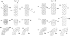
- the structure (10) comprises at least one hollow flexible unit (11) comprising at least one elastic deformable material. More specifically, the hollow flexible unit (11) comprises at least two first helicoids (H1) having a generatrix and a first twist direction and at least two second helicoids (H2) having a generatrix and a second twist direction opposite to the first twist direction, resulting in said first and second helicoids being intertwined, said intertwined helicoids being trimmed around their centers along a direction parallel to said generatrixes so as to form said hollow flexible unit (11) of trimmed (intertwined) helicoids.
- H1 first helicoids
- H2 second helicoids
- these helicoids are ruled helicoids, preferably closed helicoid and ideally, normal helicoids.
- Other variants of helicoids may be used, but the problem of the symmetry of the mobility of the manipulator explain these preferences.
- intertwined here means that two helicoids of opposite direction will intersect each other such that they in fact form a single structural element.
- the term intercross could also be used but since the two helicoids are merged at their intersections, the term intertwined has been chosen without implying any limitation.
- each first (H1) and second (H2) helicoids are offset from, respectively, the same other first (H1) and second (H2) helicoids by an offset angle (OA) radially from the center, such that the first and second helicoids (H1, H2) are equally distributed across the periphery of the hollow flexible unit (11), the offset angle of the first helicoids (H1) having the same value as the offset angle of the second helicoids (H2).
- OA offset angle
- said hollow flexible unit (11) is tailored in height such that said helicoids describe at least one full revolution within the height of said hollow flexible unit (11).
- several units can be used in lines, as segments or sections of manipulators having various lengths.
- the two ends of the unit (11) comprise a crown linking the ends of the helicoids in a plane orthogonal to the axis of generatrix, but such crown is not necessary for the structure and/or the manipulators, although it can advantageously be used for the fixation of some component of the robot or mechatronic manipulator, as detailed below.
- said first and second helicoids (H1, H2) both have a same radius (RH).
- RH radius
- the generatrixes of said first and second helicoids (H1, H2) are colinear. Such arrangements are also preferred for obtaining a symmetrical structure having a more reliable behavior in every direction, but other variants are possible.
- said helicoids (H1, H2) are trimmed according to a trimming radius lower than the radius (RH) of the helicoids (H1, H2) so as to obtain a remaining width (W) of the trimmed helicoids, defined by the difference between the radius (RH) of the helicoids and the trimming radius, enabling to define a width to radius (W/R) ratio of the trimmed helicoids forming said hollow flexible unit (11).
- trimmed or “trimming” are used in the present application to designate the fact that the structure is hollow in its center along its longitudinal axis.
- Such hollow shape can be obtained by an actual trimming for removing material at the center, but it can be obtained by simply molding or 3D printing or any other techniques without requiring an actual removal of material but rather a direct production of a hollow structure.
- the structure is called "of architecture material” because it comprises at least one material (obtained for example by extrusion or 3D printing and/or cutting, trimming, etc. or any other technique known in the art) which is tailored for displaying a shape or "architecture" complying to a specific arrangement of the material allowing to reach the purposes of the present invention, as detailed below.
- architectured materials leverage geometry to tune their physical properties.
- Architectured structures display a variety of mechanical properties as a function of their geometry. They allow for low level control of the dynamics of the designed structure and the interactions with the environment The present invention achieves its goals by using a novel type of architecture material in particular thanks to an optimized stiffness.
- the axial stiffness and the bending stiffness are two different properties which generates problems for designing manipulators having workspace and compliance enabling it to perform tasks that require intelligent environmental interactions and safe-human interactions.
- the bending stiffness and the axial stiffness are two key parameters that drive the resulting workspace, compliance and sensitivity to perturbations. To identify how the design affects these performance parameters, it is first necessary to understand the relationship between geometry and stiffness properties. The inventors of the present invention therefore designed structures and manipulators comprising trimmed intertwined helicoids.
- these stiffnesses are largely driven by their geometrical parameters.
- these are the helicoid thickness (T), the helicoid width (W), the number of helicoids (NH) number and the helical angle (HA), as shown in Figure 1 .
- FEM Finite Element Method
- ⁇ stiff is approximately constant with thickness (T) while it increases with the 3,45 power of width to radius ratio (W/R), as shown in figure 3c .
- W/R width to radius ratio
- trimmed intertwined helicoids enable a large range of possible absolute bending stiffnesses whilst the relative stiffness ratio ⁇ stiff can also be varied significantly. They can also be controlled by independent geometric parameters.
- the axial and bending stiffness ratio ⁇ stiff can be tuned by adjusting the width to radius ratio (W/R) while the thickness (T) can be tuned to get desired absolute stiffness.
- the present invention provides for some embodiments in which said width to radius (W/R) ratio is configured to differentially tune the axial stiffness and the bending stiffness of the flexible hollow unit, within a range of width to radius (W/R) ratios comprised between 0,1 and 1, preferably between 0,3 and 0,5.
- said elastic deformable material of the helicoids (H1, H2) has a thickness (T) which is determined as a function of the radius (RH) of the helicoids and configured to tune the absolute stiffness of the flexible hollow unit (11), within a range of thickness to radius ratios which are comprised between 0,01 and 0,5, preferably between 0,1 and 0,3.
- Varying the helical angle ( ⁇ ) and number of helicoids (NH) was also investigated and can be used to vary the stiffness, but it also introduces undesired behaviors in some range of parameters. For example, when the helices angle is high, compression causes stress concentration, and the deformation behavior becomes nonlinear. Similarly, when the helicoid density becomes high, thin-wall cylinder buckling emerges. Therefore, a compromised is preferred for these parameters within the ranges detailed below, and the present invention proposes to take advantage of the interesting features of the thickness and width to radius ratio for tuning the structure (10) to the desired behavior according to the various possible applications.
- Sine-wave structures which are known in the art, were compared to the present helicoidal structures and it has been observed that the sine wave structures tend to exhibit to high compression stresses at, and around, the crossing area between the various adjacent sine waves along the structure. Therefore, the deformation behavior of sine wave structures tends to become nonlinear. Furthermore, helicoidal structures are preferred in the present application for their reliability and the possibility of tuning the axial and bending stiffnesses separately and thus enable a wide range of applications.
- said first and second helicoids both have a helical angle (HA), defining the degree of their twist, both angles having the same absolute value. As in general, this angle is measured at their outer edge in the example of values described below.
- said angles (HA) of the helicoids have a value comprised between one and seventy degrees, preferably between twenty and fifty degrees.
- said hollow flexible unit (11) comprises the same number (NH) of first helicoids (H1) and second helicoids (H2), said number (NH) being comprised between three and twelve, preferably six.
- the present invention also concerns a mechatronic manipulator, this term because used to define a device able to be moved and to actuate (e.g., grip and move) objects.
- mechatronic manipulator (1) thus has one or more degrees of freedom and is able to be controlled by a control unit (CU) connected to one or more actuators (2) able to actuate said mechatronic manipulator (1).
- CU control unit
- Such combination of a manipulator with an actuator and a control unit forms, as itself, a system which can be defined as a robot, as long as the control unit is able to be programed for executing various movements and tasks.
- the details about the control unit, its hardware (processor or the like) and software are not necessary because they are standard for those of skills in the art.
- Such mechatronic manipulator has the advantage to include at least one structure (10) according to the present invention, extending from a proximal end able to be connected to the control unit (CU) to a distal end aiming for objects to be manipulated in the environment of the manipulator (1).
- the manipulator is used vertically (as shown in figures 5 and 6 for example), preferably with the proximal end upward and the distal end downward, for obtaining a hanging "elephant-trunk" manipulator.
- the manipulator can be used as standing (proximal end downward and distal end upward) but it can also be used horizontally.
- the hanging configuration is preferred for limiting power consumption and wear of the manipulator at rest.
- the present invention provides for various sizes of the structures (10) and thus for various arrangements of the structures within the manipulator.
- said multiple hollow flexible units (11) of each section (S) are connected to each other in series or in parallel or both, in an arborescence. An arrangement in several parallel or diverging lines would result in a manipulator mimicking a robotic hand, which is a good example of the wide variety of configurations possible.
- the present invention which is thus not limited to the examples shown in the figures.
- said structure (10) comprises one or several sections (S) composed of one or several hollow flexible units (11), each section (S) being actuated in one direction by a single actuator (2) or in several directions by a single set of actuators (2).
- each unit is defined by the full revolution of its helicoids and it might be terminated by a crown linking the ends of the helicoids on each end of the unit, as illustrated in the figures.
- Such crown may have the same width to radius (W/R) ratio as the unit itself but may have a higher W/R ratio, for example for receiving other components, like the sliding guides for example or any other useful component, for example among those described below.
- each section (S) and/or hollow flexible unit (11) comprise a proximal and a distal end defined as those of said of the structure (10), said actuators (2) imparting the motion to the distal end of each section (S) and/or hollow flexible unit (11).
- each section (S) can comprise one or several units (11)
- the actuators may impart motion to the distal end of each section, which is located at the distal end of one of their units (11).
- it is sufficient to impart motion at the end of one section especially in the case of actuators comprising cables pulling the distal end of the section, but other variants are possible, in particular for other types of actuators.
- the actuators (2) of a single set of actuators impart a motion to its section (S) at locations which are equally distributed across the periphery of the hollow flexible units (11).
- the locations of a set of actuators (2) imparting a motion to a given section (S) are offset from the locations of other sets of actuators (2) imparting a motion to other sections (S), from an offset angle having a value determined as a function of the number of sections arranged in series.
- the set of actuators (2) comprises two to four actuators, preferably three actuators, for covering every direction of motion by a combined actuation from the control unit (CU).
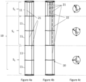
- Figure 4c shows an example of such distribution of the actuators along various sections.
- manipulators tendons for example
- each set of three actuators of one section is offset from the set of three actuators of the adjacent section.
- a combined actuation hollow for example compression of a section (by actuating the set at the same time) and/or a bending of various sections to various degrees in various directions.
- the actuators (2) of a section (S) are decoupled from the actuators of the other sections (S) even when the sections are in series, such that the motion imparted to a section is not imparted to upstream sections of the series.
- Figure 4a illustrates a non-limiting example of a "coupled manipulator" in which the actuators, called “tendons” (because they are formed by pulling cables) of each section are actuated along the upstream sections.
- Figure 4b illustrates and an independent manipulator in which, for example by the fact that the tendons of each section is enclosed within a guide, such as Bowden cables.
- a guide such as Bowden cables.
- the sections can comprise one or more hollow flexible units (11) and their number may vary along the longitudinal axis of the manipulator.
- said actuators (2) of a section (S) comprise a cable (21) extending from the distal end of said section (S) to the proximal end of said structure (10) wherein a motor (20) enables to pull on the cable (21), so as to actuate said section (S).
- the cable can be connected to a pulley or string wheel at the proximal end of the manipulator, wherein a motor is driving the rotation to exert a tension on the cables and impart motions to the manipulator, in a manner similar to a tendon in the human body.
- actuations are possible for those of skills in the art who will still appreciate the efficiency and low cost of such tendons.
- the cable (21) of the actuators (2) of a section (S) is arranged within a guiding tube (22) which extends from the proximal end of this section (S) to the proximal end of the structure (10), such that an upstream section (S) is not imparted by the motion of this section (S).
- a guiding tube (22) which extends from the proximal end of this section (S) to the proximal end of the structure (10), such that an upstream section (S) is not imparted by the motion of this section (S).
- the cable can be similar to Bowden cables, but the same feature of decoupling between sections applies to other types of actuators, (such as for example electromagnetic or electrostatic actuators).
- said guiding tube (22) of a section (S) is configured to slide relative to an upstream section (S) along sliding guides (23) enabling that the motion of the upstream section does not impart the downstream section (S).
- sliding guides 23) can also be used in the case of other types of actuators than the cables (Bowden cables in particular) and they may be form by guiding clips on any section in which the actuators of the downstream sections can slide in order to impart motion of these sections without any disturbance from the motion of the upstream sections. This sliding of the actuator may imply the retraction of the actuator up to the proximal end of the manipulator, for example at the level of the motor.
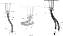
- Figure 5 shows an example of such arrangement wherein the housing tubes (22) of the cables (21) form loops at the level of the motor and these loops can increase in size when the manipulator is actuated toward said motor.
- FIG 6b An example of such movement is shown in figure 6b.
- Figures 6a, 6b and 6c shows illustrative and non-limiting examples of motions of the manipulator according to some embodiments of the present invention, as tested in some experiments.
- Figure 6a shows the open-loop precision of the manipulator
- Figure 6b shows the large workspace of the manipulator
- Figure 6a shows the compliance of the manipulator, which can safely and efficiently interact with a human in performing tasks.
- At least the distal end of the manipulator (1) comprises a distal section having at least one gripping actuator (24) imparting a contraction of the diameter of the most distal hollow flexible unit (11) for enabling the grasping of objects in the environment of the manipulator (1).
- Figures 5 , 6a and 6c show examples of the use of such gripping end.
- the gripping end comprises a peripheral tendon encircling a diameter close to the distal end of the distal section of the manipulator, which is thus contracted by pulling on a dedicated Bowden cable.
- the gripper at the distal end can be of various types and eventually made by a combination of several smaller manipulators arranged according to some embodiments of the present invention (preferably at least three manipulators forming three fingers allowing to grasp objects). It is thus understood by reading the present application, that the present invention provides for various combinations of structures and manipulators.
- a robotic system can indeed comprise several manipulators designed as described herein and combined to form a complex arm able to perform complex tasks. The low cost, the softness of the material used are other advantages of the present invention, in addition to the tunability of the structure to the applications and tasks to be performed.
Landscapes
- Engineering & Computer Science (AREA)
- Robotics (AREA)
- Mechanical Engineering (AREA)
- Manipulator (AREA)
Priority Applications (2)
| Application Number | Priority Date | Filing Date | Title |
|---|---|---|---|
| EP23194124.6A EP4516461A1 (de) | 2023-08-29 | 2023-08-29 | Struktur aus architected material für einen mechatronischen manipulator und mechatronischer manipulator damit |
| PCT/EP2024/073263 WO2025045640A1 (en) | 2023-08-29 | 2024-08-20 | Structure of architectured material for a mechatronic manipulator and mechatronic manipulator using the same |
Applications Claiming Priority (1)
| Application Number | Priority Date | Filing Date | Title |
|---|---|---|---|
| EP23194124.6A EP4516461A1 (de) | 2023-08-29 | 2023-08-29 | Struktur aus architected material für einen mechatronischen manipulator und mechatronischer manipulator damit |
Publications (1)
| Publication Number | Publication Date |
|---|---|
| EP4516461A1 true EP4516461A1 (de) | 2025-03-05 |
Family
ID=87863613
Family Applications (1)
| Application Number | Title | Priority Date | Filing Date |
|---|---|---|---|
| EP23194124.6A Withdrawn EP4516461A1 (de) | 2023-08-29 | 2023-08-29 | Struktur aus architected material für einen mechatronischen manipulator und mechatronischer manipulator damit |
Country Status (2)
| Country | Link |
|---|---|
| EP (1) | EP4516461A1 (de) |
| WO (1) | WO2025045640A1 (de) |
Families Citing this family (1)
| Publication number | Priority date | Publication date | Assignee | Title |
|---|---|---|---|---|
| CN120926181B (zh) * | 2025-10-14 | 2026-02-03 | 华东交通大学 | 一种具有变刚度特性的空间螺旋柔顺机构 |
Citations (5)
| Publication number | Priority date | Publication date | Assignee | Title |
|---|---|---|---|---|
| JPS63260776A (ja) * | 1987-04-17 | 1988-10-27 | 株式会社小松製作所 | 可撓腕ロボツトの制御装置 |
| US20130298759A1 (en) * | 2010-09-30 | 2013-11-14 | Christine Rotinat-Libersa | Integrated mecatronic structure for portable manipulator assembly |
| US20150343649A1 (en) * | 2014-05-28 | 2015-12-03 | Richard Galinson | Tentacle mechanism |
| US20220193932A1 (en) * | 2019-04-11 | 2022-06-23 | Nhk Spring Co., Ltd. | Flexible member |
| WO2022240794A2 (en) * | 2021-05-10 | 2022-11-17 | Board Of Regents, The University Of Texas System | Programmable elastomer robot system and methods |
-
2023
- 2023-08-29 EP EP23194124.6A patent/EP4516461A1/de not_active Withdrawn
-
2024
- 2024-08-20 WO PCT/EP2024/073263 patent/WO2025045640A1/en active Pending
Patent Citations (5)
| Publication number | Priority date | Publication date | Assignee | Title |
|---|---|---|---|---|
| JPS63260776A (ja) * | 1987-04-17 | 1988-10-27 | 株式会社小松製作所 | 可撓腕ロボツトの制御装置 |
| US20130298759A1 (en) * | 2010-09-30 | 2013-11-14 | Christine Rotinat-Libersa | Integrated mecatronic structure for portable manipulator assembly |
| US20150343649A1 (en) * | 2014-05-28 | 2015-12-03 | Richard Galinson | Tentacle mechanism |
| US20220193932A1 (en) * | 2019-04-11 | 2022-06-23 | Nhk Spring Co., Ltd. | Flexible member |
| WO2022240794A2 (en) * | 2021-05-10 | 2022-11-17 | Board Of Regents, The University Of Texas System | Programmable elastomer robot system and methods |
Also Published As
| Publication number | Publication date |
|---|---|
| WO2025045640A1 (en) | 2025-03-06 |
Similar Documents
| Publication | Publication Date | Title |
|---|---|---|
| Thomas et al. | Surgical applications of compliant mechanisms: A review | |
| Qi et al. | A novel continuum manipulator design using serially connected double-layer planar springs | |
| Merlet | Optimal design for the micro parallel robot MIPS | |
| Seibold et al. | Prototype of instrument for minimally invasive surgery with 6-axis force sensing capability | |
| Arata et al. | A new hand exoskeleton device for rehabilitation using a three-layered sliding spring mechanism | |
| Grebenstein et al. | Antagonistically driven finger design for the anthropomorphic DLR hand arm system | |
| Simone et al. | A soft five-fingered hand actuated by shape memory alloy wires: design, manufacturing, and evaluation | |
| Choi et al. | Design of a spring backbone micro endoscope | |
| US20130298759A1 (en) | Integrated mecatronic structure for portable manipulator assembly | |
| Maeno et al. | Miniature five-fingered robot hand driven by shape memory alloy actuators | |
| US12318156B2 (en) | Extensible continuum manipulator | |
| Qi et al. | A novel continuum-style robot with multilayer compliant modules | |
| Faudzi et al. | Soft manipulator using thin McKibben actuator | |
| EP4516461A1 (de) | Struktur aus architected material für einen mechatronischen manipulator und mechatronischer manipulator damit | |
| Chang et al. | Design of a novel tremor suppression device using a linear delta manipulator for micromanipulation | |
| Gafford et al. | Toward medical devices with integrated mechanisms, sensors, and actuators via printed-circuit MEMS | |
| Mustaza et al. | Stiffness control for soft surgical manipulators | |
| Sun et al. | Cruciate-ligament-inspired compliant joints: Application to 3D-printed continuum surgical robots | |
| Chen et al. | Soft robotic joints with anisotropic stiffness by multiobjective topology optimization | |
| Nanayakkara | Handbook on soft robotics | |
| Kaplanoglu et al. | Design and PID Control of Tendon-Driven Continuum Robot for Finger Rehabilitation | |
| Esser et al. | Encoding desired deformation profiles in endoscope-like soft robots | |
| Deashapriya et al. | Biomimetic flexible robot arm design and kinematic analysis of a novel flexible robot arm | |
| Zoppi et al. | Design of a microrobotic wrist for needle laparoscopic surgery | |
| Bachta et al. | The cardiolock project: Design of an active stabilizer for cardiac surgery |
Legal Events
| Date | Code | Title | Description |
|---|---|---|---|
| PUAI | Public reference made under article 153(3) epc to a published international application that has entered the european phase |
Free format text: ORIGINAL CODE: 0009012 |
|
| STAA | Information on the status of an ep patent application or granted ep patent |
Free format text: STATUS: THE APPLICATION HAS BEEN PUBLISHED |
|
| AK | Designated contracting states |
Kind code of ref document: A1 Designated state(s): AL AT BE BG CH CY CZ DE DK EE ES FI FR GB GR HR HU IE IS IT LI LT LU LV MC ME MK MT NL NO PL PT RO RS SE SI SK SM TR |
|
| STAA | Information on the status of an ep patent application or granted ep patent |
Free format text: STATUS: THE APPLICATION IS DEEMED TO BE WITHDRAWN |
|
| 18D | Application deemed to be withdrawn |
Effective date: 20250906 |