EP4516459A2 - Hydraulisches werkzeug mit anzeigeleuchte - Google Patents
Hydraulisches werkzeug mit anzeigeleuchte Download PDFInfo
- Publication number
- EP4516459A2 EP4516459A2 EP25152966.5A EP25152966A EP4516459A2 EP 4516459 A2 EP4516459 A2 EP 4516459A2 EP 25152966 A EP25152966 A EP 25152966A EP 4516459 A2 EP4516459 A2 EP 4516459A2
- Authority
- EP
- European Patent Office
- Prior art keywords
- head
- work piece
- hydraulic tool
- light
- predetermined criterion
- Prior art date
- Legal status (The legal status is an assumption and is not a legal conclusion. Google has not performed a legal analysis and makes no representation as to the accuracy of the status listed.)
- Pending
Links
Images








Classifications
-
- B—PERFORMING OPERATIONS; TRANSPORTING
- B25—HAND TOOLS; PORTABLE POWER-DRIVEN TOOLS; MANIPULATORS
- B25B—TOOLS OR BENCH DEVICES NOT OTHERWISE PROVIDED FOR, FOR FASTENING, CONNECTING, DISENGAGING, OR HOLDING
- B25B27/00—Hand tools, specially adapted for fitting together or separating parts or objects whether or not involving some deformation, not otherwise provided for
- B25B27/02—Hand tools, specially adapted for fitting together or separating parts or objects whether or not involving some deformation, not otherwise provided for for connecting objects by press fit or detaching same
- B25B27/10—Hand tools, specially adapted for fitting together or separating parts or objects whether or not involving some deformation, not otherwise provided for for connecting objects by press fit or detaching same inserting fittings into hoses
-
- B—PERFORMING OPERATIONS; TRANSPORTING
- B25—HAND TOOLS; PORTABLE POWER-DRIVEN TOOLS; MANIPULATORS
- B25F—COMBINATION OR MULTI-PURPOSE TOOLS NOT OTHERWISE PROVIDED FOR; DETAILS OR COMPONENTS OF PORTABLE POWER-DRIVEN TOOLS NOT PARTICULARLY RELATED TO THE OPERATIONS PERFORMED AND NOT OTHERWISE PROVIDED FOR
- B25F3/00—Associations of tools for different working operations with one portable power-drive means; Adapters therefor
-
- B—PERFORMING OPERATIONS; TRANSPORTING
- B25—HAND TOOLS; PORTABLE POWER-DRIVEN TOOLS; MANIPULATORS
- B25F—COMBINATION OR MULTI-PURPOSE TOOLS NOT OTHERWISE PROVIDED FOR; DETAILS OR COMPONENTS OF PORTABLE POWER-DRIVEN TOOLS NOT PARTICULARLY RELATED TO THE OPERATIONS PERFORMED AND NOT OTHERWISE PROVIDED FOR
- B25F5/00—Details or components of portable power-driven tools not particularly related to the operations performed and not otherwise provided for
- B25F5/005—Hydraulic driving means
-
- B—PERFORMING OPERATIONS; TRANSPORTING
- B25—HAND TOOLS; PORTABLE POWER-DRIVEN TOOLS; MANIPULATORS
- B25F—COMBINATION OR MULTI-PURPOSE TOOLS NOT OTHERWISE PROVIDED FOR; DETAILS OR COMPONENTS OF PORTABLE POWER-DRIVEN TOOLS NOT PARTICULARLY RELATED TO THE OPERATIONS PERFORMED AND NOT OTHERWISE PROVIDED FOR
- B25F5/00—Details or components of portable power-driven tools not particularly related to the operations performed and not otherwise provided for
- B25F5/02—Construction of casings, bodies or handles
Definitions
- the present disclosure relates generally to power tools. More particularly, the present disclosure relates to a hydraulic power tool.
- a hydraulic tool can be used to crimp, shear, or cut a work piece, among other examples.
- a hydraulic pump is typically utilized for actuating the tool.
- the force exerted by the pump can be used for closing jaws of the tool to perform a crimping, cutting, or shearing action on the work piece at a desired location.
- deviations from acceptable tolerance ranges for some crimping, shearing, or cutting actions can be hard to detect by visual inspection.
- work site conditions such as the work piece being suspended high above the ground can add difficulty. Therefore, there is a need for a tool with improved user feedback regarding whether a proper cut, shear, or crimp has been performed on a work piece.
- One aspect of the disclosure provides a hydraulic tool that includes a head at a first end of the hydraulic tool, wherein the head is configured to apply a mechanical force to a work piece; a body comprising a first surface; a back portion comprising: a second surface at a second end of the hydraulic tool that is opposite the first end; a third surface that is between the first surface and the second surface, wherein the third surface is inclined with respect to the first surface and the second surface; an indicator light; and a window positioned on the third surface, wherein the window covers the indicator light; and a grip that extends from the body away from the first surface.
- Another aspect of the disclosure provides a method of operating a hydraulic tool, the method including: positioning a work piece within a head; activating a first actuator of the hydraulic tool, thereby causing the head to close upon the work piece; making a determination that a cutting, crimping, or shearing operation that satisfies a predetermined criterion has been performed on the work piece by the head; and causing an indicator light to emit a light that corresponds to the determination.
- Yet another aspect of the disclosure provides a method of operating a hydraulic tool, the method including: positioning a work piece within a head; activating a first actuator of the hydraulic tool, thereby causing the head to close upon the work piece; making a determination that a cutting, crimping, or shearing operation that satisfies a predetermined criterion has not been performed on the work piece by the head; and causing an indicator light to emit a light that corresponds to the determination.
- Hydraulic crimpers and cutters are types of hydraulic power tools for performing crimping and cutting work on a work piece. Hydraulic tools often include a hydraulic pump for pressurizing hydraulic fluid and transferring the fluid to a cylinder in the power tool.
- the cylinder includes a piston that can extend toward a cutting head of the power tool.
- the piston exerts a force on the cutting head, which may typically include opposed jaws with certain cutting features depending on the particular configuration of the power tool.
- the force exerted by the piston may be used for closing the jaws to perform cutting on a work piece, such as a wire, at a targeted cutting location.
- Certain hydraulic cutting tools include a cutting tool head with jaws that pivot at a pivot point.
- Each of the jaws can include a cutting surface and a respective ear or extension.
- a portion of the cutting surface can be integral with or mounted to the ear, and a pivot pin can extend through each ear to form the pivot point.
- the cutting surfaces adjacent to the ear can pass by each other.
- the overlap of the cutting surfaces can prevent the jaws from fully cutting the work piece.
- the jaws may jam or bind before the work piece is fully cut.
- a cutting motion can cause jaws to flex or be pushed laterally away from the work piece.
- a cutter is effective when the cutting tool can make a full cut on a work piece and avoid binding. Effective cutters also reduce or eliminate undesired flex and force on the jaws and blades during a cutting action.
- a cutting tool configured to provide a full, controllable cut while limiting the force that urges jaws of the cutting tool laterally away from a work piece during a cutting action may be useful.
- a hydraulic tool with improved user feedback regarding whether a proper cut, shear, crimp, or other operation has been performed on a work piece.
- a user reaches above the user's head to put the tool in position to operate on the work piece.
- the user holds the hydraulic tool well below the user's eyes ( e.g., at waist level) to put the tool in position to operate on the work piece.
- a hydraulic tool can provide a feedback mechanism that is convenient in both situations.
- the hydraulic tool can include an indicator light that indicates whether the hydraulic tool has successfully or unsuccessfully operated on the work piece. The indicator light is positioned such that it is convenient for the user to view whether the tool is raised above the user's head or at waist level, for example.
- the hydraulic tool 100 also includes a back portion 110 that includes a second surface 112 at a second end 114 of the hydraulic tool 100 that is opposite the first end 104.
- the back portion 110 also includes a third surface 116 that is between the first surface 108 and the second surface 112.
- the third surface 116 is inclined with respect to the first surface 108 and the second surface 112 and defines a plane that is skewed relative to the longitudinal axis 124 (e.g., plane is non-parallel to the longitudinal axis 124). In some embodiments, the plane defined by the third surface 116 is not perpendicular to the axis 124.
- the second surface 112 is perpendicular to the longitudinal axis 124.
- the third surface 116 includes a first portion 126 that abuts the second surface 112 and a second portion 128 that abuts the first surface 108.
- a first edge 115 is formed where the first portion 126 abuts the second surface 112 (see, for example, FIG. 2 ).
- a second edge 117 is formed where the second portion 128 abuts the first surface 108 (see, for example, FIG. 2 ).
- Each of the first and second edges 115, 117 can be configured as rounded exterior, obtuse corners.
- the hydraulic tool 100 also includes an indicator light 118 and a window 120 positioned on the third surface 116.
- the window 120 e.g., a snap on plastic window
- the indicator light 118 e.g., a multi-color light emitting diode (LED) array, a discrete LED, or a light bulb.
- the window 120 is disposed proximate to the first edge 115.
- the hydraulic tool 100 includes a grip 122 that extends from the body 106 away from the first surface 108.
- the grip 122 extends generally away from the body 106 perpendicularly to the longitudinal axis 124.
- the grip 122 takes a form of a pistol grip, but other examples are possible.
- the grip 122 includes a first actuator 130 (e.g., a trigger) that, when activated, causes the head 102 to close ( e.g., upon the work piece).
- the grip 122 includes a second actuator 132 that, when activated, causes the head 102 to open ( e.g., away from the work piece).
- the positions of the first actuator 130 and the second actuator 132 can be reversed.
- the first and second actuators 130, 132 can be disposed along the grip 122 at an overlapping position.
- the hydraulic tool 100 is configured ( e.g., via a control system) to make a first determination that a cutting, crimping, or shearing operation (or another type of operation) that satisfies a predetermined criterion has been performed on the work piece by the head 102 and configured to cause the indicator light 118 to emit a first light that corresponds to the first determination.
- the indicator light 118 emitting a green light could indicate that the operation performed by the head 102 on the work piece satisfies the predetermined criterion.
- predetermined criteria for evaluating an operation performed by the hydraulic tool 100 are discussed in more detail below.
- the hydraulic tool 100 is also configured to make a second determination that a cutting, crimping, or shearing operation that satisfies a predetermined criterion has not ( e.g., yet) been performed on the work piece by the head and configured to cause the indicator light to emit a second light that corresponds to the second determination.
- the indicator light 118 emitting a red light could indicate that the operation performed by the head 102 on the work piece does not ( e.g., yet) satisfy the predetermined criterion.
- predetermined criteria for evaluating an operation performed by the hydraulic tool 100 are discussed in more detail below.
- FIG. 2 is a close up view of the hydraulic tool from the back and left. That is, FIG. 2 is a close up view of the back portion 110.
- the first portion 126 is separated from the second portion 128 by a boundary 129 (e.g., a seam).
- the boundary 129 bisects the window 120 along a longitudinal axis of the window 120.
- the longitudinal axis of the window 120 is formed below the longitudinal axis 124 and extends perpendicular to the longitudinal axis 124.
- the window 120 is elongated in a direction substantially parallel to the boundary 129 that separates the first portion 126 from the second portion 128.
- the window 120 is rounded such that it conforms to the first portion 126 and the second portion 128 so that the window 120 extends into each of the first portion 126 and the second portion 128.
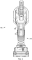
- FIG. 3 is a front end view of the hydraulic tool 100.
- Each of the first and second actuators 130, 132 extend laterally across the grip 122.
- the first actuator 130 is separated from the second actuator 132 by a portion of the grip 122.
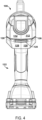
- FIG. 4 is a back end view of the hydraulic tool 100 including the window 120.
- the window 120 extends between a first end 131 and a second end 133 across a perpendicular bisector 134.
- the perpendicular bisector 134 perpendicularly intersections the longitudinal axis 124.
- the longitudinal sides of the window 120 form a curve between the first end 131 and the second end 133 so that the first end 131 and the second end 133 are disposed closer to the longitudinal axis 124 than the portion of the window proximate to the perpendicular bisector 134.
- FIGS. 5-8 illustrate additional views of the hydraulic tool 100 according to embodiments of the invention.
- FIG. 5 is a right side view of the hydraulic tool 100
- FIG. 6 is a left side view of the hydraulic tool 100
- FIG. 7 is a top end view of the hydraulic tool 100
- FIG. 8 is a bottom end view of the hydraulic tool 100.
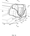
- FIGS. 9-16 illustrate the hydraulic tool 100 according to another embodiment of the invention.
- another example window 120 defines a shape that is different from the window 120 shown in FIGS. 1-8 .
- the window 120 is elongated in a direction that is substantially perpendicular to the boundary 129 that separates the first portion 126 from the second portion 128. As such, the window 120 is rounded such that it conforms to the second surface 112, the first portion 126, and the second portion 128 so that the window 120 extends into each of the first portion 126 and the second portion 128.
- FIGS. 11-16 illustrate additional view of the hydraulic tool 100 according to embodiments of the invention.
- FIG. 11 is a front end view of the hydraulic tool 100 shown in FIGS. 9 and 10
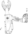
- FIG. 12 is a back end view of the hydraulic tool 100 shown in FIGS. 9-11
- FIG. 13 is a right side view of the hydraulic tool 100 shown in FIGS. 9-12
- FIG. 14 is a left side view of the hydraulic tool 100 shown in FIGS. 9-13
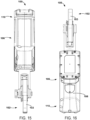
- FIG. 15 is a top end view of the hydraulic tool 100 shown in FIGS. 9-14
- FIG. 16 is a bottom end view of the hydraulic tool 100 shown in FIGS. 9-15 .
- FIGS. 17-19 illustrate the hydraulic tool 100 according to another embodiment of the invention.
- the hydraulic tool 100 includes an attachment loop 121.
- the attachment loop 121 can be used in a variety of hydraulic tools, including the embodiments of the hydraulic tool 100 shown in each of FIGS. 1-8 and FIG. 9-16 .
- FIGS. 17 and 19 illustrate the hydraulic tool 100 with the attachment loop 121 in an extended position and FIG. 18 illustrates the hydraulic tool 100 with the attachment loops 121 in an upright position.
- the attachment loop 121 is attached to the back portion 110.
- the adjustable loop 121 In the retracted position as shown, for example, in FIGS. 1-16 , the adjustable loop 121 is between the head 102 and the second surface 112. In the extended position shown in FIG. 17 , the adjustable loop 121 extends beyond the second surface 112. In the upright position shown in FIG. 18 , the adjustable loop 121 is between the head 102 and the second surface 112 (e.g., as projected onto the longitudinal axis of the hydraulic tool 100). In some embodiments, the adjustable loop 121 is can be used for hanging the hydraulic tool 100 on a hook or a belt loop, for example.
- FIG. 20 is a block diagram of a method 200 of operating a hydraulic tool, such as the hydraulic tool 100 (e.g., any embodiment of the hydraulic tool 100 described herein).
- the method 200 will be described below with reference to the hydraulic tool 100.
- the method 200 includes positioning the work piece within the head 102. For example, a user could place a work piece between the jaws 103.
- the method 200 includes activating the first actuator 130 of the hydraulic tool 100, thereby causing the head 102 ( e.g., the jaws 103) to close upon the work piece.
- the method 200 includes making a determination that a cutting, crimping, or shearing operation that satisfies a predetermined criterion has been performed on the work piece by the head 102.
- making the determination can include a control system of the hydraulic tool 100 determining that a pressure that has been applied by the head 102 upon the work piece exceeds a threshold pressure (for example, the pressure threshold can be between approximately 5,000 psi and approximately 10,000 psi, or, for example, approximately 7,200 psi).
- making the determination can include the control system determining that a distance 210 (see FIG. 1 ) between jaws 103 of the head 102 is less than a threshold distance.
- Such threshold distance can correspond to a completion of an action performed on a work piece.
- an approximately zero inch distance i.e., the jaws are touching
- a particular non-zero distance can correspond to a completed crimp of the work piece.
- the method 200 includes causing the indicator light 118 to emit a light (e.g., a green light) that corresponds to the determination.
- FIG. 21 is a block diagram of a method 300 of operating a hydraulic tool, such as the hydraulic tool 100.
- the method 300 will be described below with reference to the hydraulic tool 100.
- the method 300 includes positioning the work piece within the head 102. For example, a user could place a work piece between the jaws 103.
- the method 300 includes activating the first actuator 130 of the hydraulic tool 100, thereby causing the head 102 ( e.g., the jaws 103) to close upon the work piece.
- the method 300 includes making a determination that a cutting, crimping, or shearing operation that satisfies a predetermined criterion has not ( e.g., yet) been performed on the work piece by the head 102.
- making the determination can include a control system of the hydraulic tool 100 determining that a pressure that has been applied by the head 102 upon the work piece has not exceeded a threshold pressure (for example, the pressure threshold can be between approximately 5,000 psi and approximately 10,000, or, for example, approximately 7,200 psi).
- making the determination can include the control system determining that a distance 210 (see FIG.
- making the determination can include the control system determining that the first actuator 130 has been activated for at least a threshold duration.
- the method 300 includes causing the indicator light 118 to emit a light (e.g., a red light) that corresponds to the determination.
- the invention may relate to one or more of the following aspects.
Landscapes
- Engineering & Computer Science (AREA)
- Mechanical Engineering (AREA)
- Manufacturing Of Electrical Connectors (AREA)
- Shearing Machines (AREA)
- Machine Tool Sensing Apparatuses (AREA)
- Measuring Fluid Pressure (AREA)
Applications Claiming Priority (3)
| Application Number | Priority Date | Filing Date | Title |
|---|---|---|---|
| US202063012506P | 2020-04-20 | 2020-04-20 | |
| EP21724898.8A EP4139091B1 (de) | 2020-04-20 | 2021-04-20 | Hydraulisches werkzeug mit anzeigeleuchte |
| PCT/US2021/028211 WO2021216588A2 (en) | 2020-04-20 | 2021-04-20 | Hydraulic tool with indicator light |
Related Parent Applications (2)
| Application Number | Title | Priority Date | Filing Date |
|---|---|---|---|
| EP21724898.8A Division EP4139091B1 (de) | 2020-04-20 | 2021-04-20 | Hydraulisches werkzeug mit anzeigeleuchte |
| EP21724898.8A Division-Into EP4139091B1 (de) | 2020-04-20 | 2021-04-20 | Hydraulisches werkzeug mit anzeigeleuchte |
Publications (2)
| Publication Number | Publication Date |
|---|---|
| EP4516459A2 true EP4516459A2 (de) | 2025-03-05 |
| EP4516459A3 EP4516459A3 (de) | 2025-11-26 |
Family
ID=75888221
Family Applications (2)
| Application Number | Title | Priority Date | Filing Date |
|---|---|---|---|
| EP25152966.5A Pending EP4516459A3 (de) | 2020-04-20 | 2021-04-20 | Hydraulisches werkzeug mit anzeigeleuchte |
| EP21724898.8A Active EP4139091B1 (de) | 2020-04-20 | 2021-04-20 | Hydraulisches werkzeug mit anzeigeleuchte |
Family Applications After (1)
| Application Number | Title | Priority Date | Filing Date |
|---|---|---|---|
| EP21724898.8A Active EP4139091B1 (de) | 2020-04-20 | 2021-04-20 | Hydraulisches werkzeug mit anzeigeleuchte |
Country Status (4)
| Country | Link |
|---|---|
| US (3) | US11999043B2 (de) |
| EP (2) | EP4516459A3 (de) |
| CN (2) | CN222726595U (de) |
| WO (1) | WO2021216588A2 (de) |
Families Citing this family (4)
| Publication number | Priority date | Publication date | Assignee | Title |
|---|---|---|---|---|
| US11597065B2 (en) * | 2019-09-24 | 2023-03-07 | Ilsco, Llc | Pressure measuring device for crimping tool |
| USD1012650S1 (en) * | 2020-12-15 | 2024-01-30 | Ridge Tool Company | Pressing tool |
| USD1042068S1 (en) * | 2021-05-19 | 2024-09-17 | Gustav Klauke Gmbh | Hydraulic press tool |
| EP4559629A1 (de) * | 2023-11-21 | 2025-05-28 | Nanjing Chervon Industry Co., Ltd. | Handwerkzeugmaschine und zubehöraufnahme |
Family Cites Families (19)
| Publication number | Priority date | Publication date | Assignee | Title |
|---|---|---|---|---|
| US5727417A (en) * | 1995-09-22 | 1998-03-17 | Greenlee Textron Inc. | Portable battery powered crimper |
| EP0941813B1 (de) | 1998-03-10 | 2003-10-29 | Ridge Tool Ag | Presswerkzeug und Pressverfahren zum Verpressen von Fittings |
| DE10000868C2 (de) * | 2000-01-12 | 2002-09-19 | Franz Viegener Ii Gmbh & Co Kg | Presswerkzeug und Verfahren zum Eichen eines Presswerkzeuges |
| JP2003211374A (ja) | 2002-01-21 | 2003-07-29 | Hitachi Koki Co Ltd | 電動工具 |
| US7306052B2 (en) | 2004-10-05 | 2007-12-11 | Illinois Tool Works Inc. | Multi-position utility hook assembly for tool |
| EP2022607B1 (de) | 2007-07-26 | 2011-03-09 | Makita Corporation | Hakenstruktur für ein elektrisches Werkzeug |
| JP5577216B2 (ja) | 2009-12-10 | 2014-08-20 | 株式会社マキタ | 電動工具用フック及び電動工具用フックを取り付けた電動工具 |
| JP5525358B2 (ja) * | 2010-07-16 | 2014-06-18 | 株式会社マキタ | バッテリパックを電源とする電動工具及びそのアダプタ |
| JP5555594B2 (ja) | 2010-10-07 | 2014-07-23 | 株式会社マキタ | 電動工具用吊り下げ具及び電動工具用吊り下げ具を装着した電動工具 |
| US9457461B2 (en) | 2013-08-06 | 2016-10-04 | Robert Bosch Tool Corporation | Dual axis hook assembly for a power tool |
| US9434056B2 (en) * | 2013-12-12 | 2016-09-06 | Ingersoll-Rand Company | Impact tools with pressure verification and/or adjustment |
| DE102014206271B4 (de) | 2014-04-02 | 2024-02-22 | Robert Bosch Gmbh | Handwerkzeugmaschine, Verfahren zum Betreiben einer Handwerkzeugmaschine |
| DE102015218447B4 (de) | 2014-12-16 | 2025-01-23 | Robert Bosch Gmbh | Akkupack für eine Handwerkzeugmaschine mit Leuchtelement |
| EP3307453B1 (de) * | 2015-06-15 | 2022-08-03 | Milwaukee Electric Tool Corporation | Hydraulisches crimpwerkzeug |
| US11108205B2 (en) | 2016-09-22 | 2021-08-31 | Airlane Technologies—Sarl | Dieless crimping tool |
| US10899027B2 (en) * | 2017-05-15 | 2021-01-26 | Hubbell Inorporated | Portable in-line hydraulic tool |
| WO2019152439A1 (en) * | 2018-01-30 | 2019-08-08 | Milwaukee Electric Tool Corporation | Power tool |
| EP3774145A4 (de) * | 2018-04-10 | 2022-04-13 | Hubbell Incorporated | Tragbares inline-schneidwerkzeug mit stabilisator |
| WO2020069531A1 (en) * | 2018-09-28 | 2020-04-02 | Hubbell Incorporated | Power tool with crimp localization |
-
2021
- 2021-04-20 EP EP25152966.5A patent/EP4516459A3/de active Pending
- 2021-04-20 EP EP21724898.8A patent/EP4139091B1/de active Active
- 2021-04-20 CN CN202322713390.4U patent/CN222726595U/zh active Active
- 2021-04-20 CN CN202190000354.XU patent/CN219902016U/zh active Active
- 2021-04-20 WO PCT/US2021/028211 patent/WO2021216588A2/en not_active Ceased
- 2021-04-20 US US17/235,540 patent/US11999043B2/en active Active
-
2024
- 2024-05-15 US US18/665,097 patent/US12384011B2/en active Active
-
2025
- 2025-07-22 US US19/276,801 patent/US20250345917A1/en active Pending
Also Published As
| Publication number | Publication date |
|---|---|
| EP4516459A3 (de) | 2025-11-26 |
| US20250345917A1 (en) | 2025-11-13 |
| CN222726595U (zh) | 2025-04-08 |
| CN219902016U (zh) | 2023-10-27 |
| WO2021216588A2 (en) | 2021-10-28 |
| US12384011B2 (en) | 2025-08-12 |
| EP4139091B1 (de) | 2025-02-26 |
| WO2021216588A3 (en) | 2021-11-25 |
| US11999043B2 (en) | 2024-06-04 |
| EP4139091A2 (de) | 2023-03-01 |
| US20210323136A1 (en) | 2021-10-21 |
| US20240300083A1 (en) | 2024-09-12 |
Similar Documents
| Publication | Publication Date | Title |
|---|---|---|
| US11999043B2 (en) | Hydraulic tool with indicator light | |
| US11597070B2 (en) | Hydraulic power tool | |
| CN114025680B (zh) | 用于机动化外科器械的马达控制调整的机构 | |
| CN114080191B (zh) | 用于更新马达组件参数的具有射频识别标签的外科系统 | |
| CN114025683B (zh) | 用于适当砧座附接外科缝合头部组件的机构 | |
| US20250073873A1 (en) | Hydraulic power tool | |
| EP2313236B1 (de) | Werkzeugkopf-einheiten für pressvorrichtungen | |
| EP3213880A1 (de) | Hydraulische pumpe für ein hydrodynamisches kompressionswerkzeug | |
| EP2653113B1 (de) | Lineare chirurgische klammergerät | |
| CN108213559B (zh) | 用于压缩或切割工具的工作头和相关液动压缩或切割工具 | |
| EP3241503A1 (de) | Klammermagazin und medizinischer anastomat mit verwendung davon | |
| CN105583430B (zh) | 手持式工具机装置 | |
| WO2018002134A3 (en) | Surgical stapler, anvil for a surgical stapler, and a method of stapling tissue | |
| EP2156730A2 (de) | Schneidewerkzeug | |
| EP1943962A3 (de) | Verbesserter gebogener Endeffektor für chirurgische Klammergeräte | |
| EP2540459A1 (de) | Schneidewerkzeug | |
| EP2474272A3 (de) | Chirurgische Klammervorrichtung | |
| US11826839B2 (en) | Armored cable cutter with cutting blade retention | |
| EP3794358B1 (de) | System zum erreichen von spitzen, d. h. zur untersuchung der spannung in elektrischen kabeln | |
| CN107928733B (zh) | 钉仓组件及外科手术器械 | |
| KR101657423B1 (ko) | 파지력의 조절이 가능한 공작기계의 툴 로딩용 클램핑 장치 | |
| US20140001225A1 (en) | Stapler | |
| CN108125697B (zh) | 外科手术器械 | |
| CA2390262A1 (en) | Cutting and crimping device | |
| CN107553586A (zh) | 一种纸张打孔器的动力装置 |
Legal Events
| Date | Code | Title | Description |
|---|---|---|---|
| PUAI | Public reference made under article 153(3) epc to a published international application that has entered the european phase |
Free format text: ORIGINAL CODE: 0009012 |
|
| STAA | Information on the status of an ep patent application or granted ep patent |
Free format text: STATUS: THE APPLICATION HAS BEEN PUBLISHED |
|
| AC | Divisional application: reference to earlier application |
Ref document number: 4139091 Country of ref document: EP Kind code of ref document: P |
|
| AK | Designated contracting states |
Kind code of ref document: A2 Designated state(s): AL AT BE BG CH CY CZ DE DK EE ES FI FR GB GR HR HU IE IS IT LI LT LU LV MC MK MT NL NO PL PT RO RS SE SI SK SM TR |
|
| RIC1 | Information provided on ipc code assigned before grant |
Ipc: B25F 5/02 20060101AFI20250804BHEP Ipc: B25B 27/10 20060101ALI20250804BHEP Ipc: B25F 5/00 20060101ALI20250804BHEP |
|
| PUAL | Search report despatched |
Free format text: ORIGINAL CODE: 0009013 |
|
| AK | Designated contracting states |
Kind code of ref document: A3 Designated state(s): AL AT BE BG CH CY CZ DE DK EE ES FI FR GB GR HR HU IE IS IT LI LT LU LV MC MK MT NL NO PL PT RO RS SE SI SK SM TR |
|
| RIC1 | Information provided on ipc code assigned before grant |
Ipc: B25F 5/02 20060101AFI20251023BHEP Ipc: B25B 27/10 20060101ALI20251023BHEP Ipc: B25F 5/00 20060101ALI20251023BHEP |
|
| STAA | Information on the status of an ep patent application or granted ep patent |
Free format text: STATUS: REQUEST FOR EXAMINATION WAS MADE |
|
| 17P | Request for examination filed |
Effective date: 20260526 |