EP4516366A1 - Elektroschrank mit feuerlöscher - Google Patents
Elektroschrank mit feuerlöscher Download PDFInfo
- Publication number
- EP4516366A1 EP4516366A1 EP24197788.3A EP24197788A EP4516366A1 EP 4516366 A1 EP4516366 A1 EP 4516366A1 EP 24197788 A EP24197788 A EP 24197788A EP 4516366 A1 EP4516366 A1 EP 4516366A1
- Authority
- EP
- European Patent Office
- Prior art keywords
- cabinet
- fire
- extinguishing material
- fire extinguishing
- sensor
- Prior art date
- Legal status (The legal status is an assumption and is not a legal conclusion. Google has not performed a legal analysis and makes no representation as to the accuracy of the status listed.)
- Pending
Links
Images




Classifications
-
- A—HUMAN NECESSITIES
- A62—LIFE-SAVING; FIRE-FIGHTING
- A62C—FIRE-FIGHTING
- A62C37/00—Control of fire-fighting equipment
- A62C37/36—Control of fire-fighting equipment an actuating signal being generated by a sensor separate from an outlet device
- A62C37/38—Control of fire-fighting equipment an actuating signal being generated by a sensor separate from an outlet device by both sensor and actuator, e.g. valve, being in the danger zone
- A62C37/40—Control of fire-fighting equipment an actuating signal being generated by a sensor separate from an outlet device by both sensor and actuator, e.g. valve, being in the danger zone with electric connection between sensor and actuator
-
- A—HUMAN NECESSITIES
- A62—LIFE-SAVING; FIRE-FIGHTING
- A62C—FIRE-FIGHTING
- A62C3/00—Fire prevention, containment or extinguishing specially adapted for particular objects or places
- A62C3/16—Fire prevention, containment or extinguishing specially adapted for particular objects or places in electrical installations, e.g. cableways
-
- A—HUMAN NECESSITIES
- A62—LIFE-SAVING; FIRE-FIGHTING
- A62C—FIRE-FIGHTING
- A62C37/00—Control of fire-fighting equipment
- A62C37/04—Control of fire-fighting equipment with electrically-controlled release
-
- A—HUMAN NECESSITIES
- A62—LIFE-SAVING; FIRE-FIGHTING
- A62C—FIRE-FIGHTING
- A62C37/00—Control of fire-fighting equipment
- A62C37/36—Control of fire-fighting equipment an actuating signal being generated by a sensor separate from an outlet device
Definitions
- the present disclosure relates generally to electronic equipment cabinets and more specifically relates to electronic equipment cabinets, such as computer equipment cabinets, having fire extinguishing capabilities.
- an electronic equipment cabinet can include one or more mounting rails for supporting electronic equipment, such as computing equipment, within the cabinet, at least one fire sensor, and at least one fire extinguisher.
- the fire sensor(s) can be configured to detect fire within the cabinet and/or outside the cabinet.
- the fire sensor(s) can include an internal fire sensor configured to detect fire within the cabinet and/or an external fire sensor configured to detect fire outside the cabinet.
- the at least one fire sensor can include a plurality of temperature sensors located within the cabinet.
- the temperature sensors can detect a fire within the cabinet and/or a location of the fire within the cabinet.
- the at least one fire extinguisher can direct fire extinguishing material toward the location of the fire within the cabinet.
- the at least one fire extinguisher can include a plurality of nozzles. In at least one example, each nozzle can direct fire extinguishing material toward a different location within the cabinet.
- a controller can monitor the temperature sensors and open one or more of the nozzles configured to direct fire extinguishing material toward the location of the fire within the cabinet.
- the at least one fire extinguisher can include at least one nozzle configured to direct fire extinguishing material toward different locations within the cabinet.
- the nozzle can be articulated to direct the fire extinguishing material toward the location of the fire within the cabinet.
- a controller can monitor the temperature sensors and articulate, orient, or otherwise adapt the at least one nozzle to direct fire extinguishing material toward the location of the fire within the cabinet.
- the at least one fire extinguisher can direct fire extinguishing material throughout the cabinet, essentially engulfing the cabinet's interior with the fire extinguishing material, rather than directing the fire extinguishing material to a specific location within the cabinet.
- the fire extinguishing material can be a dry powder, a non-conductive liquid, fire extinguishing pods, fire extinguishing gas, another fire extinguishing material, or any combination thereof.
- the at least one fire sensor can detect a direction of a fire external to the cabinet.
- the at least one fire sensor can include a temperature sensor configured to detect an air temperature of the air entering the cabinet.
- the at least one fire extinguisher can include at least one nozzle configured to direct fire extinguishing material away from the cabinet. In at least one example, the at least one fire extinguisher can include at least one nozzle configured to direct fire extinguishing material encircling the cabinet.
- the at least one fire extinguisher can include a plurality of nozzles. In at least one example, each nozzle can direct fire extinguishing material in a different direction. In at least one example, a controller can monitor the at least one fire sensor and open one or more of the nozzles configured to direct fire extinguishing material in the direction of the fire external to the cabinet.
- the at least one fire extinguisher can include a dispenser configured to eject fire extinguishing pods outward from the cabinet.
- the dispenser can eject the fire extinguishing pods encircling the cabinet.
- the at least one fire sensor can detect a direction of a fire external to the cabinet.
- the dispenser can eject the fire extinguishing pods in the direction of the fire external to the cabinet.
- a solar shield can be mounted upon the cabinet.
- the solar shield can reduce the solar induced heat within the cabinet.
- the solar shield can house one or more fire sensor(s) and/or one or more fire extinguisher(s).
- the at least one fire extinguisher can include an inclined surface configured to direct fire extinguishing material toward a direction of a fire external to the cabinet. In at least one example, the at least one fire extinguisher can include a stopper configured to release the fire extinguishing material upon detection of the fire external to the cabinet. In at least one example, the at least one fire extinguisher can include a plunger configured to direct fire extinguishing material toward a direction of a fire external to the cabinet.
- the at least one fire extinguisher can include a tank configured to store fire extinguishing material and/or a conduit surrounding the cabinet.
- the conduit can direct the fire extinguishing material toward a direction of a fire external to the cabinet upon detection of the fire external to the cabinet.
- the cabinet can include a cover configured to cover at least a portion of the at least one fire extinguisher. In at least one example, the cover can uncover the portion of the at least one fire extinguisher upon detection of a fire external to the cabinet.
- Couple can include any method or device for securing, binding, bonding, fastening, attaching, joining, inserting therein, forming thereon or therein, communicating, or otherwise associating, for example, mechanically, magnetically, electrically, chemically, operably, directly or indirectly with intermediate elements, one or more pieces of members together and can further include without limitation integrally forming one functional member with another in a unity fashion.
- the coupling can occur in any direction, including rotationally.
- all parts and components of the disclosure that are capable of being physically embodied inherently include imaginary and real characteristics regardless of whether such characteristics are expressly described herein, including but not limited to characteristics such as axes, ends, inner and outer surfaces, interior spaces, tops, bottoms, sides, boundaries, dimensions (e.g., height, length, width, thickness), mass, weight, volume and density, among others.
- each block in a flowchart may represent a module, segment, or portion of code, which can include one or more executable instructions for implementing the specified logical function(s).
- the function(s) noted in the block(s) might occur out of the order depicted in the figures.
- blocks shown in succession may, in fact, be executed substantially concurrently.
- each block of flowchart illustration can be implemented by special purpose hardware-based systems that perform the specified functions or acts, or combinations of special purpose hardware and computer instructions.
- an electronic equipment cabinet can include one or more mounting rails for supporting electronic equipment, such as computing equipment, within the cabinet, at least one fire sensor for sensing a fire in or about the cabinet, and at least one fire extinguisher for supporting extinguishment of a fire in or about the cabinet.
- the fire sensor(s) can be adapted for detecting fire within the cabinet and/or outside the cabinet, which can include comprising internal and/or external fire sensor(s).
- the fire extinguisher(s) can be adapted for extinguishing or helping extinguish a fire within the cabinet and/or outside the cabinet, which can include comprising internal and/or external fire extinguisher(s).
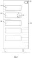
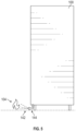
- FIG. 1 is a sectional elevation view of one of many examples of an electronic equipment cabinet according to the disclosure.
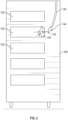
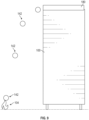
- FIG. 2 is another sectional elevation view of one of many examples of an electronic equipment cabinet according to the disclosure.
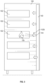
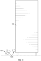
- FIG. 3 is a sectional elevation view of another one of many examples of an electronic equipment cabinet according to the disclosure.
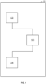
- FIG. 4 is a block diagram of an electronic equipment cabinet system according to the disclosure.
- FIG. 5 is an elevation view of still another one of many examples of an electronic equipment cabinet according to the disclosure.
- FIG. 6 is an elevation view of another one of many examples of an electronic equipment cabinet according to the disclosure.
- FIG. 7 is an elevation view of another one of many examples of an electronic equipment cabinet according to the disclosure.
- FIG. 8 is another elevation view of one of many examples of an electronic equipment cabinet according to the disclosure.
- FIG. 1 is a sectional elevation view of one of many examples of an electronic equipment cabinet according to the disclosure.
- FIG. 2 is another sectional elevation view of one of many examples of an electronic equipment cabinet according to the disclosure.
- FIG. 9 is an elevation view of still another one of many examples of an electronic equipment cabinet according to the disclosure.
- FIG. 10 is an elevation view of another one of many examples of an electronic equipment cabinet according to the disclosure.
- FIG. 11 is an elevation view of still another one of many examples of an electronic equipment cabinet according to the disclosure.
- FIG. 12 is a partial close-up view of a fire extinguishing sub-system of the electronic equipment cabinet of FIG. 11 .
- FIG. 13 is an elevation view of still another one of many examples of an electronic equipment cabinet according to the disclosure.
- FIG. 14 is a partial close-up view of a fire extinguishing sub-system of the electronic equipment cabinet of FIG. 13 .
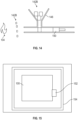
- FIG. 15 is a plan view of still another one of many examples of an electronic equipment cabinet according to the disclosure.
- FIG. 16 is a plan view of still another one of many examples of an electronic equipment cabinet according to the disclosure.
- FIG. 17 is a partial close-up view of a fire extinguishing sub-system of the electronic equipment cabinet of FIG. 16 .
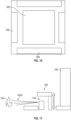
- FIGS. 1-17 are described in conjunction with one another, at least because different features shown in different ones of FIGS. 1-17 can be combined with one another and/or omitted in one or more examples.
- an electronic equipment cabinet 100 can include one or more mounting rails for supporting electronic equipment 102 within the cabinet 100, at least one fire sensor 120, and at least one fire extinguisher 140.
- the electronic equipment 102 can include computing equipment, such as central processing units (CPUs). Graphical processing units (GPUs), servers, data storage devices, network devices, uninterruptible power supplies (UPSs), or any combination thereof.
- CPUs central processing units
- GPUs Graphical processing units
- servers data storage devices
- network devices network devices
- UPSs uninterruptible power supplies
- the fire sensor(s) 120 can be configured to detect fire 104 within the cabinet 100 and/or outside the cabinet 100.
- the fire sensor(s) 120 can include an internal fire sensor configured to detect fire 104 within the cabinet 100 and/or an external fire sensor configured to detect fire 104 outside the cabinet 100.
- the fire extinguisher(s) 140 can be configured to extinguish fire 104 within the cabinet 100 and/or outside the cabinet 100.
- the fire extinguisher(s) 140 can include an internal fire extinguisher configured to extinguish fire 104 within the cabinet 100 and/or an external fire extinguisher configured to extinguish fire 104 outside the cabinet 100.
- the at least one fire sensor 120 can include one or more temperature sensors, one or more smoke detectors, one or more infrared sensors, or any combination thereof, located within or otherwise coupled to the cabinet 100.
- the fire sensor(s) 120 can be or include an ionization detector, a photoelectric detector, a combination ionization/photoelectric detector, a heat detector, or any combination thereof.
- the fire sensor(s) 120 can detect a fire 104 within the cabinet 100 and/or a location of the fire 104 within the cabinet 100.
- the at least one fire extinguisher 140 can direct fire extinguishing material 142 toward the location of the fire 104 within the cabinet 100.
- the at least one fire extinguisher 140 can include a plurality of nozzles 144.
- each nozzle can direct fire extinguishing material 142 toward a different location within the cabinet 100.
- a controller 160 can monitor the fire sensor(s) 120 and open one or more of the nozzles 144 configured to direct fire extinguishing material 142 toward the location of the fire 104 within the cabinet 100.
- the controller 160 can monitor the fire sensor(s) 120, determine the location of the fire 104 within the cabinet 100, using the fire sensor(s) 120, determine which nozzles are configured to direct fire extinguishing material 142 toward the location of the fire 104 within the cabinet 100, and open one or more of the nozzles 144 configured to direct fire extinguishing material 142 toward the location of the fire 104 within the cabinet 100. In at least one example, the controller 160 can leave closed and/or confirm closure of one or more nozzles 144 configured to direct fire extinguishing material 142 toward a location(s) other than the location of the fire 104 within the cabinet 100.
- the at least one fire extinguisher 140 can include at least one nozzle configured to direct fire extinguishing material 142 toward different locations within the cabinet 100.
- the nozzle 144 can be articulated to direct the fire extinguishing material 142 toward the location of the fire 104 within the cabinet 100.
- a controller 160 can monitor the fire sensor(s) 120 and articulate, orient, or otherwise adapt the at least one nozzle 144 to direct fire extinguishing material 142 toward the location of the fire 104 within the cabinet 100.
- the controller 160 can monitor the fire sensor(s) 120, determine the location of the fire 104 within the cabinet 100, using the fire sensor(s) 120, and articulate, orient, or otherwise adapt the at least one nozzle 144 to direct fire extinguishing material 142 toward the location of the fire 104 within the cabinet 100.
- the at least one fire extinguisher 140 can direct fire extinguishing material 142 throughout the cabinet 100, essentially engulfing the cabinet's 100 interior with the fire extinguishing material 142, rather than directing the fire extinguishing material 142 to a specific location within the cabinet 100.
- the fire extinguishing material 142 can be or include a sprayable fire extinguishing material 142A (such as a dry powder, a non-conductive liquid, fire extinguishing gas, or any combination thereof), a pod-based fire extinguishing material 142B, or any combination thereof.
- the fire extinguishing material 142 can be or include a fire retardant material, in whole or in part.
- the at least one fire sensor 120 can detect a direction of a fire 104 external to the cabinet 100.
- the at least one fire sensor 120 can include one or more temperature sensors, one or more smoke detectors, one or more infrared sensors, or any combination thereof, configured to detect an air temperature of the air entering the cabinet 100, and can be located inside and/or outside the cabinet 100.
- the at least one fire sensor 120 can include one or more temperature sensors, one or more smoke detectors, one or more infrared sensors, or any combination thereof, whether mounted within the cabinet 100 or external thereto, in whole or in part.
- a smoke detector can be an ionizing-type smoke detector, which can include an amount of radioactive material between two electrically charged plates that ionizes the air and causes current to flow between the plates. When smoke enters between the plates, it can disrupt the flow of ions, thus reducing the flow of current and activating the smoke detector.
- a smoke detector, or another type of smoke detector can be used in conjunction with one or more temperature sensors, one or more infrared sensors, or any combination thereof, such as to reduce the chances of a false positive reading regarding the presence of a fire.
- the at least one fire extinguisher 140 can include at least one nozzle configured to direct fire extinguishing material 142 away from the cabinet 100. In at least one example, the at least one fire extinguisher 140 can include at least one nozzle configured to direct fire extinguishing material 142 encircling the cabinet 100. In at least one example, the at least one fire extinguisher 140 can include one or more nozzle(s) configured to direct fire extinguishing material 142 all around the cabinet 100, thereby extinguishing any fire near the cabinet 100 regardless of the direction of the fire 104.
- the at least one fire extinguisher 140 can include a plurality of nozzles. In at least one example, each nozzle 144 can direct fire extinguishing material 142 in a different direction from the cabinet 100. In at least one example, a controller 160 can monitor the at least one fire sensor 120 and open one or more of the nozzles 144 configured to direct fire extinguishing material 142 in the direction of the fire 104 external to the cabinet 100.
- the controller 160 can monitor the fire sensor(s) 120, determine the location of the fire 104 external to the cabinet 100, using the fire sensor(s) 120, determine which nozzles 144 are configured to direct fire extinguishing material 142 toward the direction of the fire 104 external to the cabinet 100, and open one or more of the nozzles 144 configured to direct fire extinguishing material 142 toward the direction of the fire 104 external to the cabinet 100. In at least one example, the controller 160 can leave closed those nozzles 144 not configured to direct fire extinguishing material 142 toward the direction of the fire 104 external to the cabinet 100.
- the at least one fire extinguisher 140 can include a dispenser configured to eject fire extinguishing material 142, such as fire extinguishing pods 142B, outward from the cabinet 100.
- the dispenser 140 can eject the fire extinguishing pods 142B all around, or otherwise encircling, the cabinet 142.
- the at least one fire sensor can detect a direction of a fire external to the cabinet.
- the dispenser 140 can eject the fire extinguishing pods 142B all around the cabinet 100, thereby extinguishing any fire near the cabinet 100 regardless of the direction of the fire 104.
- the dispenser 140 can eject the fire extinguishing pods 142B in the direction of the fire 104 external to the cabinet 100.
- a solar shield 180 can be mounted upon the cabinet 100. In at least one example, the solar shield 180 can reduce the solar induced heat within the cabinet 100. In at least one example, the solar shield 180 can house one or more fire sensor(s) 120, one or more fire extinguisher(s) 140, one or more controllers 160, or any combination thereof.
- the at least one fire extinguisher, or dispenser, 140 can include an inclined surface 146, such as an inclined tray or funnel, configured to direct fire extinguishing material 142 toward a direction of a fire 104 external to the cabinet 100.
- fire extinguishing pods 142B can be or include balls of fire extinguishing material(s) and can be loaded into or onto the funnel or tray 146.
- the at least one fire extinguisher 140 can include one or more stoppers, or gates, 148 configured to release the fire extinguishing material upon detection of the fire external to the cabinet.
- one or more of the stoppers, or gates, 148 can be opened by the controller 160 upon the fire sensor(s) 120 detecting a fire 104.
- the controller 160 can monitor the fire sensor(s) 120, determine the location of the fire 104 external to the cabinet 100, using the fire sensor(s) 120, determine which stoppers, or gates, 148 are configured to direct fire extinguishing material 142 toward the direction of the fire 104 external to the cabinet 100, open one or more of the stoppers, or gates, 148 configured to direct fire extinguishing material 142 toward the direction of the fire 104 external to the cabinet 100, or any combination thereof.
- the at least one fire extinguisher 140 can include a plunger 150 configured to direct fire extinguishing material 142 toward a direction of a fire 104 external to the cabinet 100.
- the plunger 150 can force sprayable fire extinguishing material 142A through a nozzle 144, thereby spraying the fire extinguishing material 142A toward the fire 104.
- the at least one fire extinguisher 140 can include a tank 152 configured to store fire extinguishing material 142 and/or a conduit 154 surrounding the cabinet 100.
- the tank 152 can store the fire extinguishing material 142A in liquid or gaseous form.
- the tank 152 can store the fire extinguishing material 142A in a pressurized state or rely on gravity feed of the fire extinguishing material 142A.
- the conduit 154 can direct the fire extinguishing material 142A toward a direction of a fire 104 external to the cabinet 100 upon detection of the fire 104 external to the cabinet 100.
- the conduit 154 can include one or more nozzles 144 and the controller 160 can monitor the fire sensor(s) 120, determine the location of the fire 104 external to the cabinet 100, using the fire sensor(s) 120, determine which nozzles 144 are configured to direct fire extinguishing material 142A toward the direction of the fire 104 external to the cabinet 100, open one or more of the nozzles 144 configured to direct fire extinguishing material 142A toward the direction of the fire 104 external to the cabinet 100, or any combination thereof.
- the conduit 154 can be temperature sensitive, such that the fire 104 external to the cabinet 100 can melt a portion of the conduit 154 thereby releasing the fire extinguishing material 142A toward the direction of the fire 104 external to the cabinet 100.
- the conduit 154 can include temperature sensitive nozzles 144, such that the fire 104 external to the cabinet 100 can melt a portion of the nozzles 144 thereby releasing the fire extinguishing material 142A toward the direction of the fire 104 external to the cabinet 100.
- the cabinet 100 can include one or more covers 156 configured to cover at least a portion of the at least one fire extinguisher 140. In at least one example, the cover 156 can uncover the portion of the at least one fire extinguisher 140 upon detection of a fire 104 external to the cabinet 100.
- the controller 160 can monitor the fire sensor(s) 120, determine the location of the fire 104 external to the cabinet 100, using the fire sensor(s) 120, determine which cover(s) 156 cover nozzle(s) 144 configured to direct fire extinguishing material 142 toward the direction of the fire 104 external to the cabinet 100, raise or otherwise open the appropriate cover(s) 156, thereby triggering one or more of the nozzles 144 configured to direct fire extinguishing material 142 toward the direction of the fire 104 external to the cabinet 100, or any combination thereof.
- an electronic equipment cabinet can include one or more mounting rails for supporting electronic equipment, such as computing equipment, within the cabinet, at least one fire sensor, and at least one fire extinguisher.
- the fire sensor(s) can be configured to detect fire within the cabinet and/or outside the cabinet.
- the fire sensor(s) can include an internal fire sensor configured to detect fire within the cabinet and/or an external fire sensor configured to detect fire outside the cabinet.
- the at least one fire sensor can include a plurality of temperature sensors located within the cabinet.
- the temperature sensors can detect a fire within the cabinet and/or a location of the fire within the cabinet.
- the at least one fire extinguisher can direct fire extinguishing material toward the location of the fire within the cabinet.
- the at least one fire extinguisher can include a plurality of nozzles. In at least one example, each nozzle can direct fire extinguishing material toward a different location within the cabinet.
- a controller can monitor the temperature sensors and open one or more of the nozzles configured to direct fire extinguishing material toward the location of the fire within the cabinet.
- the at least one fire extinguisher can include at least one nozzle configured to direct fire extinguishing material toward different locations within the cabinet.
- the nozzle can be articulated to direct the fire extinguishing material toward the location of the fire within the cabinet.
- a controller can monitor the temperature sensors and articulate, orient, or otherwise adapt the at least one nozzle to direct fire extinguishing material toward the location of the fire within the cabinet.
- the at least one fire extinguisher can direct fire extinguishing material throughout the cabinet, essentially engulfing the cabinet's interior with the fire extinguishing material, rather than directing the fire extinguishing material to a specific location within the cabinet.
- the fire extinguishing material can be a dry powder, a non-conductive liquid, fire extinguishing pods, fire extinguishing gas, another fire extinguishing material, or any combination thereof.
- the at least one fire sensor can detect a direction of a fire external to the cabinet.
- the at least one fire sensor can include a temperature sensor configured to detect an air temperature of the air entering the cabinet.
- the at least one fire extinguisher can include at least one nozzle configured to direct fire extinguishing material away from the cabinet. In at least one example, the at least one fire extinguisher can include at least one nozzle configured to direct fire extinguishing material encircling the cabinet.
- the at least one fire extinguisher can include a plurality of nozzles. In at least one example, each nozzle can direct fire extinguishing material in a different direction. In at least one example, a controller can monitor the at least one fire sensor and open one or more of the nozzles configured to direct fire extinguishing material in the direction of the fire external to the cabinet.
- the at least one fire extinguisher can include a dispenser configured to eject fire extinguishing pods outward from the cabinet.
- the dispenser can eject the fire extinguishing pods encircling the cabinet.
- the at least one fire sensor can detect a direction of a fire external to the cabinet.
- the dispenser can eject the fire extinguishing pods in the direction of the fire external to the cabinet.
- a solar shield can be mounted upon the cabinet.
- the solar shield can reduce the solar induced heat within the cabinet.
- the solar shield can house one or more fire sensor(s) and/or one or more fire extinguisher(s).
- the at least one fire extinguisher can include a tank configured to store fire extinguishing material and/or a conduit surrounding the cabinet.
- the conduit can direct the fire extinguishing material toward a direction of a fire external to the cabinet upon detection of the fire external to the cabinet.
- the cabinet can include a cover configured to cover at least a portion of the at least one fire extinguisher. In at least one example, the cover can uncover the portion of the at least one fire extinguisher upon detection of a fire external to the cabinet.
- the devices, systems and methods can be implemented for numerous different types and sizes in numerous different industries.
- the various methods and examples of the devices, systems and methods can be included in combination with each other to produce variations of the disclosed methods and examples. Discussion of singular elements can include plural elements and vice versa.
- the order of steps can occur in a variety of sequences unless otherwise specifically limited.
- the various steps described herein can be combined with other steps, interlineated with the stated steps, and/or split into multiple steps.
- elements have been described functionally and can be embodied as separate components or can be combined into components having multiple functions.
Landscapes
- Health & Medical Sciences (AREA)
- Public Health (AREA)
- Business, Economics & Management (AREA)
- Emergency Management (AREA)
- Fire Alarms (AREA)
Applications Claiming Priority (1)
| Application Number | Priority Date | Filing Date | Title |
|---|---|---|---|
| IN202321059237 | 2023-09-04 |
Publications (1)
| Publication Number | Publication Date |
|---|---|
| EP4516366A1 true EP4516366A1 (de) | 2025-03-05 |
Family
ID=92633808
Family Applications (1)
| Application Number | Title | Priority Date | Filing Date |
|---|---|---|---|
| EP24197788.3A Pending EP4516366A1 (de) | 2023-09-04 | 2024-09-02 | Elektroschrank mit feuerlöscher |
Country Status (2)
| Country | Link |
|---|---|
| US (1) | US20250073513A1 (de) |
| EP (1) | EP4516366A1 (de) |
Citations (4)
| Publication number | Priority date | Publication date | Assignee | Title |
|---|---|---|---|---|
| US20130025888A1 (en) * | 2011-07-26 | 2013-01-31 | Firetrace Usa, Llc | Methods and apparatus for hot aisle/cold aisle data center fire suppression |
| CN109586179A (zh) * | 2019-01-22 | 2019-04-05 | 合肥智鼎电控自动化科技有限公司 | 一种自动灭火的智能电气柜 |
| CN111905303A (zh) * | 2020-06-28 | 2020-11-10 | 郑州云启工业设备技术有限公司 | 一种用于大数据计算机的火灾灾害安全防护方法 |
| CN112333948A (zh) * | 2020-11-06 | 2021-02-05 | 广东电网有限责任公司东莞供电局 | 一种阻燃型分格式自动化电气控制柜 |
-
2024
- 2024-09-02 EP EP24197788.3A patent/EP4516366A1/de active Pending
- 2024-09-04 US US18/823,680 patent/US20250073513A1/en active Pending
Patent Citations (4)
| Publication number | Priority date | Publication date | Assignee | Title |
|---|---|---|---|---|
| US20130025888A1 (en) * | 2011-07-26 | 2013-01-31 | Firetrace Usa, Llc | Methods and apparatus for hot aisle/cold aisle data center fire suppression |
| CN109586179A (zh) * | 2019-01-22 | 2019-04-05 | 合肥智鼎电控自动化科技有限公司 | 一种自动灭火的智能电气柜 |
| CN111905303A (zh) * | 2020-06-28 | 2020-11-10 | 郑州云启工业设备技术有限公司 | 一种用于大数据计算机的火灾灾害安全防护方法 |
| CN112333948A (zh) * | 2020-11-06 | 2021-02-05 | 广东电网有限责任公司东莞供电局 | 一种阻燃型分格式自动化电气控制柜 |
Also Published As
| Publication number | Publication date |
|---|---|
| US20250073513A1 (en) | 2025-03-06 |
Similar Documents
| Publication | Publication Date | Title |
|---|---|---|
| KR101998279B1 (ko) | 에너지 저장 시스템의 소화 장치 | |
| EP4002543B1 (de) | Batteriepack mit löscheinheit | |
| US20220407176A1 (en) | Fire mitigation system for energy storage systems | |
| KR102123685B1 (ko) | 가스감지식 ess 소화장치 | |
| KR101547869B1 (ko) | Emp 방호용 랙 | |
| CN110235272B (zh) | 电池托盘盖、带盖电池托盘以及电池的制造方法 | |
| US10892469B2 (en) | Safety compliant battery cell ejection for packaged battery cells | |
| KR101775793B1 (ko) | 전기설비함의 방열공 자동닫힘장치 | |
| AU2012286748A1 (en) | Methods and apparatus for hot aisle/cold aisle data center fire suppression | |
| US12537260B2 (en) | Energy storage unit with active ventilation system and associated method | |
| US10105563B2 (en) | Fire extinguishing device and method thereof | |
| EP4516366A1 (de) | Elektroschrank mit feuerlöscher | |
| US20160157572A1 (en) | Capture apparatus for portable electronic devices | |
| KR20200138356A (ko) | 화재 진압 기능이 있는 보관 리셉터클 | |
| CN108631179A (zh) | 一种安全系数高的系统集成控制柜 | |
| KR20260013465A (ko) | 배터리 캐비닛 | |
| CN117791014A (zh) | 一种高安全性集装箱式工商业储能系统 | |
| WO2020160765A1 (en) | Unit to test and/or charge battery cells or battery modules for electrical vehicles | |
| CN208470425U (zh) | 一种多级减震运输防护箱 | |
| KR20170138828A (ko) | 배전함용 co2 카트리지 자동 소화기 | |
| KR101418779B1 (ko) | 집중공조 서버룸 | |
| CN208882459U (zh) | 一种多级减震安全运输防护装置 | |
| US20250192577A1 (en) | Locker cabinet for storing and charging rechargeable batteries | |
| KR20120003995U (ko) | 소화장치를 구비한 천정재 | |
| CN107158635A (zh) | 一种智能消防灭火系统 |
Legal Events
| Date | Code | Title | Description |
|---|---|---|---|
| PUAI | Public reference made under article 153(3) epc to a published international application that has entered the european phase |
Free format text: ORIGINAL CODE: 0009012 |
|
| STAA | Information on the status of an ep patent application or granted ep patent |
Free format text: STATUS: THE APPLICATION HAS BEEN PUBLISHED |
|
| AK | Designated contracting states |
Kind code of ref document: A1 Designated state(s): AL AT BE BG CH CY CZ DE DK EE ES FI FR GB GR HR HU IE IS IT LI LT LU LV MC ME MK MT NL NO PL PT RO RS SE SI SK SM TR |
|
| STAA | Information on the status of an ep patent application or granted ep patent |
Free format text: STATUS: REQUEST FOR EXAMINATION WAS MADE |
|
| 17P | Request for examination filed |
Effective date: 20250902 |