EP4516264A1 - Freisetzungssystem für interventionellen herzklappenstent - Google Patents
Freisetzungssystem für interventionellen herzklappenstent Download PDFInfo
- Publication number
- EP4516264A1 EP4516264A1 EP23795664.4A EP23795664A EP4516264A1 EP 4516264 A1 EP4516264 A1 EP 4516264A1 EP 23795664 A EP23795664 A EP 23795664A EP 4516264 A1 EP4516264 A1 EP 4516264A1
- Authority
- EP
- European Patent Office
- Prior art keywords
- sleeve
- axial
- heart valve
- tube
- stroke
- Prior art date
- Legal status (The legal status is an assumption and is not a legal conclusion. Google has not performed a legal analysis and makes no representation as to the accuracy of the status listed.)
- Pending
Links
Images


Classifications
-
- A—HUMAN NECESSITIES
- A61—MEDICAL OR VETERINARY SCIENCE; HYGIENE
- A61F—FILTERS IMPLANTABLE INTO BLOOD VESSELS; PROSTHESES; DEVICES PROVIDING PATENCY TO, OR PREVENTING COLLAPSING OF, TUBULAR STRUCTURES OF THE BODY, e.g. STENTS; ORTHOPAEDIC, NURSING OR CONTRACEPTIVE DEVICES; FOMENTATION; TREATMENT OR PROTECTION OF EYES OR EARS; BANDAGES, DRESSINGS OR ABSORBENT PADS; FIRST-AID KITS
- A61F2/00—Filters implantable into blood vessels; Prostheses, i.e. artificial substitutes or replacements for parts of the body; Appliances for connecting them with the body; Devices providing patency to, or preventing collapsing of, tubular structures of the body, e.g. stents
- A61F2/02—Prostheses implantable into the body
- A61F2/24—Heart valves ; Vascular valves, e.g. venous valves; Heart implants, e.g. passive devices for improving the function of the native valve or the heart muscle; Transmyocardial revascularisation [TMR] devices; Valves implantable in the body
- A61F2/2427—Devices for manipulating or deploying heart valves during implantation
- A61F2/2436—Deployment by retracting a sheath
-
- A—HUMAN NECESSITIES
- A61—MEDICAL OR VETERINARY SCIENCE; HYGIENE
- A61F—FILTERS IMPLANTABLE INTO BLOOD VESSELS; PROSTHESES; DEVICES PROVIDING PATENCY TO, OR PREVENTING COLLAPSING OF, TUBULAR STRUCTURES OF THE BODY, e.g. STENTS; ORTHOPAEDIC, NURSING OR CONTRACEPTIVE DEVICES; FOMENTATION; TREATMENT OR PROTECTION OF EYES OR EARS; BANDAGES, DRESSINGS OR ABSORBENT PADS; FIRST-AID KITS
- A61F2/00—Filters implantable into blood vessels; Prostheses, i.e. artificial substitutes or replacements for parts of the body; Appliances for connecting them with the body; Devices providing patency to, or preventing collapsing of, tubular structures of the body, e.g. stents
- A61F2/02—Prostheses implantable into the body
- A61F2/24—Heart valves ; Vascular valves, e.g. venous valves; Heart implants, e.g. passive devices for improving the function of the native valve or the heart muscle; Transmyocardial revascularisation [TMR] devices; Valves implantable in the body
- A61F2/2412—Heart valves ; Vascular valves, e.g. venous valves; Heart implants, e.g. passive devices for improving the function of the native valve or the heart muscle; Transmyocardial revascularisation [TMR] devices; Valves implantable in the body with soft flexible valve members, e.g. tissue valves shaped like natural valves
- A61F2/2418—Scaffolds therefor, e.g. support stents
-
- A—HUMAN NECESSITIES
- A61—MEDICAL OR VETERINARY SCIENCE; HYGIENE
- A61F—FILTERS IMPLANTABLE INTO BLOOD VESSELS; PROSTHESES; DEVICES PROVIDING PATENCY TO, OR PREVENTING COLLAPSING OF, TUBULAR STRUCTURES OF THE BODY, e.g. STENTS; ORTHOPAEDIC, NURSING OR CONTRACEPTIVE DEVICES; FOMENTATION; TREATMENT OR PROTECTION OF EYES OR EARS; BANDAGES, DRESSINGS OR ABSORBENT PADS; FIRST-AID KITS
- A61F2/00—Filters implantable into blood vessels; Prostheses, i.e. artificial substitutes or replacements for parts of the body; Appliances for connecting them with the body; Devices providing patency to, or preventing collapsing of, tubular structures of the body, e.g. stents
- A61F2/02—Prostheses implantable into the body
- A61F2/24—Heart valves ; Vascular valves, e.g. venous valves; Heart implants, e.g. passive devices for improving the function of the native valve or the heart muscle; Transmyocardial revascularisation [TMR] devices; Valves implantable in the body
- A61F2/2427—Devices for manipulating or deploying heart valves during implantation
- A61F2/2439—Expansion controlled by filaments
-
- A—HUMAN NECESSITIES
- A61—MEDICAL OR VETERINARY SCIENCE; HYGIENE
- A61F—FILTERS IMPLANTABLE INTO BLOOD VESSELS; PROSTHESES; DEVICES PROVIDING PATENCY TO, OR PREVENTING COLLAPSING OF, TUBULAR STRUCTURES OF THE BODY, e.g. STENTS; ORTHOPAEDIC, NURSING OR CONTRACEPTIVE DEVICES; FOMENTATION; TREATMENT OR PROTECTION OF EYES OR EARS; BANDAGES, DRESSINGS OR ABSORBENT PADS; FIRST-AID KITS
- A61F2/00—Filters implantable into blood vessels; Prostheses, i.e. artificial substitutes or replacements for parts of the body; Appliances for connecting them with the body; Devices providing patency to, or preventing collapsing of, tubular structures of the body, e.g. stents
- A61F2/95—Instruments specially adapted for placement or removal of stents or stent-grafts
- A61F2/962—Instruments specially adapted for placement or removal of stents or stent-grafts having an outer sleeve
- A61F2/966—Instruments specially adapted for placement or removal of stents or stent-grafts having an outer sleeve with relative longitudinal movement between outer sleeve and prosthesis, e.g. using a push rod
- A61F2002/9665—Instruments specially adapted for placement or removal of stents or stent-grafts having an outer sleeve with relative longitudinal movement between outer sleeve and prosthesis, e.g. using a push rod with additional retaining means
Definitions
- the present application relates to the technical field of interventional heart valve surgery related equipment, and in particular, to a delivery system for an interventional heart valve stent.
- transcatheter valve implantation/repair has gradually matured and been widely used, especially transcatheter aortic valve implantation (TAVR/TAVI), which has sufficient evidence-based evidence and greatly reduced trauma, has been recommended by European and American guidelines for treatment of heart valve diseases, and is a milestone in the field of interventional therapy for heart valve diseases.
- TVR/TAVI transcatheter aortic valve implantation
- artificial biological valves used in the TAVI mainly include the following two types: balloon-expandable Edwards Sapien (Edwards Corporation) and self-expanding CoreValve (Medtronic Inc.).
- the TAVI technology has made remarkable progress internationally and has been initially applied in China, with equally broad prospects.
- the domestic market of heart valve devices is highly monopolized by foreign brands, and foreign-funded companies such as EdwardsLifesciences, Medtronic, LivaNova (acquired by Solin), St. Jude (acquired by Abbott) and On-X occupy about 85% of the market share.
- an artificial valve stent can be delivered to the aortic valve and opened to complete implantation of the artificial valve and restore a valve function. There are still many problems affecting accurate release of the artificial valve stent during mounting of the delivery system and the artificial valve stent.
- the present application provides a delivery device for an interventional heart valve stent to satisfy accommodation and release of a heart valve stent.
- a delivery system for an interventional heart valve stent includes:
- the delivery system for an interventional heart valve stent is detachably connected to two ends of the heart valve stent through the stent securing assembly.
- the heart valve stent is enabled to move in or out of the capsule chamber or the accommodating cavity through an axial movement of the support tube along the inner core, thus achieving a bidirectional detachable connection method.
- a release position of the heart valve stent is more accurate, thereby avoiding unnecessary adjustment work.
- the present application may further make the following improvement.
- the stent securing assembly further includes a securing member, a securing block, and a limiting member;
- the guide member includes a connecting portion and a plurality of guide arms, the connecting portion is fixedly connected to an outer wall of the support tube, and the plurality of guide arms extend towards a distal end and elastically expand outwards.
- a distal end of the guide arm includes a transition portion, the transition portion is bent towards a side adjacent to an axis of the support tube relative to the guide arm.
- the capsule chamber includes a chamber body and a barrier opening portion, the chamber body is of a straight cylindrical structure, the barrier opening portion is of in a straight cylindrical shape without an external force and is capable of being expanded into a bell-mouth shape under an external force, and an inner side of the guide arm is capable of elastically pressing the barrier opening portion.
- the barrier opening portion is provided with a plurality of axial notches, the plurality of axial notches are evenly distributed around a circumferential direction of the capsule chamber, and a portion between adjacent axial notches form a barrier strip.
- a side surface of the chamber body is provided with a plurality of curved notches with a same length, the plurality of curved notches are distributed along an axial direction of the chamber body, adjacent curved notches are staggered, and portions between gaps between two ends of curved notches are connected to form a connecting rib that is spiral along the axial direction.
- the delivery system for an interventional heart valve stent further includes a control handle and two bending adjustment handles
- the control handle is connected to a proximal end of the support tube and is capable of driving the support tube to move axially
- the control handle includes a first stroke assembly configured to control an axial movement distance of the support tube
- the two bending adjustment handles are provided at a proximal end of the inner sheath tube and a proximal end of the outer sheath tube, respectively, corresponding distal ends of the inner sheath tube and the outer sheath tube are bent in a same plane or different planes through a traction wire
- the bending adjustment handles each includes a second stroke assembly configured to control a bending curvature of the corresponding inner sheath tube or the outer sheath tube.
- control handle is arranged along an axial direction of the support tube, the two bending adjustment handles are sequentially arranged on a side of the control handle adjacent to a distal end of the support tube, the bending adjustment handle configured to adjust the inner sheath tube is arranged closer to the control handle, the bending adjustment handle includes an axial portion and a branch portion, the axial portion is arranged along the axial direction of the support tube, the proximal ends of the inner sheath tube and the outer sheath tube are fixed to the axial portions of the corresponding bending adjustment handles, the branch portion forms an acute angle with the axial portion, and the second stroke assembly is arranged on the branch portion.
- control handle includes a handle main body sleeve, a control sleeve, and a control sliding block
- the first stroke assembly includes a first stroke sleeve and a first stroke indicating member
- the handle main body sleeve is provided with an axial control slideway
- an inner side of the control sleeve drives the control sliding block to slide along the axial control slideway through threaded fit
- the support tube is fixed to a distal end of the handle main body sleeve
- the support tube extends into the distal end of the handle main body sleeve and is fixed to the control sliding block
- the first stroke sleeve is fixedly sleeved on an outer side of the control sleeve
- the first stroke sleeve is provided with a first stroke slideway arranged along an axial direction thereof
- the outer side of the control sleeve drives the first stroke indicating member to slide along the first stroke slideway through threaded fit.
- control handle further includes a dismounting member detachably mounted at a proximal end of the handle main body sleeve and connected to a proximal end of the limiting member, and when the heart valve stent is located in the capsule chamber, the limiting member is pulled by the dismounting member, so that a distal end of the limiting member releases a connection and limitation between a proximal end of the heart valve stent and the support arm.
- the axial portion includes an axial sleeve, a hemostatic valve, and a proximal fixing cover
- the axial sleeve is provided with an axial through hole
- the proximal ends of the inner sheath tube and the outer sheath tube are inserted from a distal end of corresponding axial sleeve and are fixed
- the axial sleeve is provided with a lateral line hole corresponding to the branch portion
- the hemostatic valve is arranged at the axial sleeve adjacent to a proximal end thereof and is provided with an elastically contractible hemostatic channel
- the proximal fixing cover is fixed to the proximal end of the axial sleeve and is provided with a pipeline through hole.
- the hemostatic valve includes at least one valve plate set, each valve plate set includes a valve plate sleeve and a first valve plate, a second valve plate, and a third valve plate that are arranged coaxially in sequence from a proximal end to a distal end, a first hole is formed in a middle portion of the first valve plate, and non-penetrating notches are formed on two sides of the first valve plate, the non-penetrating notches on the two sides are staggered, a middle portion of the second valve plate protrudes to the distal end and is provide with a second hole at a central position thereof, an annular step is formed on a side of the second valve plate adjacent to the third valve plate, the third valve plate includes an elastic cylinder and two elastic flaps, the elastic flaps are connected to an inner wall of the elastic cylinder, distal ends of the elastic flaps form a flap opening that is openable, the distal ends of the elastic flaps and the inner wall of the elastic cylinder are provided with elastic support ribs
- the branch portion includes a branch main body, a bending adjustment sliding block, and a bending adjustment sleeve
- the second stroke assembly includes a second stroke sleeve and a second stroke indicating member
- the branch main body includes an axial fixing tube and a guide tube that are in communication with each other
- the axial fixing tube is coaxially fixed to an outer side of the axial sleeve
- the guide tube is arranged corresponding to the lateral line hole
- the guide tube extends towards the proximal end and forms a predetermined acute angle with the axial fixing tube
- an interior of the guide tube is provided with a bending adjustment guide slideway along an axial direction thereof
- a proximal end of the traction wire is fixed to the bending adjustment sliding block
- an inner side of the bending adjustment sleeve drives the bending adjustment sliding block to slide along the bending adjustment guide slideway through threaded fit
- the second stroke sleeve is fixedly sleeved on an outer side
- An embodiment of the present application provides a delivery system for an interventional heart valve stent, which is mainly configured to deliver the heart valve stent to a patient's heart from outside a body, and includes a delivery tube assembly and a stent securing assembly.
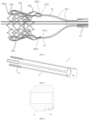
- the delivery tube assembly serves as a basic component of the delivery system, which, as shown in FIG. 1 , includes an inner core 11, a support tube 12, an inner sheath tube 13, and an outer sheath tube 14 that are sequentially and movably sleeved from inside to outside. Two ends of the inner core 11 extend out of two ends of the support tube 12, respectively. A distal end of the inner sheath tube 13 is provided with an accommodating cavity.
- a proximal end referred to is an end of the delivery system closer to a user in use, and the distal end is an end closer to a patient.
- the stent securing assembly is capable of being detachably connected to two ends of a heart valve stent 200 (see FIG. 2 ), so as to position the heart valve stent at a certain part of the stent securing assembly, generally a distal part.
- the stent securing assembly includes a capsule chamber 23, a distal end of the inner core 11 extends into the capsule chamber 23 from an opening of a proximal end of the capsule chamber 23 and is fixedly connected to the capsule chamber 23, and the support tube 12 is capable of driving the heart valve stent 200 to move axially to enable the heart valve stent 200 to move in and out of the capsule chamber 23 or from the accommodating cavity.
- An inner tube (not shown) is provided between the support tube 12 and the inner sheath tube 13, with a main function of supporting so that the support tube 12 moves in the inner tube.
- the distal end of the capsule chamber 23 is provided with a TIP head.
- the TIP head forms a pigtail shape in a natural state.
- the stent securing assembly further includes a limiting member 21, a securing member 22, and a securing block 24.
- the securing member 22 includes a support arm 221.
- the support arm 221 is connected to the support tube 12 and extends towards a distal end, and is configured to be detachably connected to a proximal end of the heart valve stent 200.
- the securing block 24 is connected to a distal end of the support tube 12 and is configured to be detachably connected to a distal end of the heart valve stent 200.
- the limiting member 21 has an elongated strip structure.
- the limiting member 21 axially extends through the support tube 12 and can extend out of the two ends of the support tube 12.
- a distal end of the limiting member 21 is configured to connect and limit the proximal end of the heart valve stent 200 and the support arm 221, so as to prevent the proximal end of the heart valve stent 200 and the support arm 221 from being separated from each other.
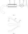
- FIG. 2 is a schematic view of a heart valve stent 200, which includes a stent body 201.
- the stent body 201 generally has an elastically compressible mesh structure, and has a first release member 202 at a proximal end thereof and a second release member 203 at a distal end thereof.
- an end portion of the support arm 221 has a limiting ring 2211.
- the first release member has a coil 2021 that can extend through the limiting ring 2211 from outside to inside.
- a distal end of the limiting member 21 can extend to an interior of the coil 2021 to clamp a connection between the coil 2021 and the limiting ring 2211, thereby preventing the coil 2021 and the limiting ring 2211 from separating from each other.
- the securing member 22 has a plurality of support arms 221.
- the number of the first release member 202 is equal to the number of the support arms 221.
- the distal end of the limiting member 21 can extend through a plurality of coils 2021 in sequence.
- the number of the support arms 22 and the number of the second release member are both three.
- the distal end of the limiting member 21 extends through the three coils 2021 in sequence.
- the number of the support arm 221 and the number of the first release members 202 are both three, the number of the limiting members 21 is also three, the distal ends of the three limiting members 21 extend through the three coils 2021 in one-to-one correspondence.
- the proximal end of the stent body 201 needs to be released, the three limiting members 21 are pulled out from the three coils, respectively, the three first release members 202 are released at the same time, which ensures the quick and smooth release of the bracket body 201.
- the securing block 24 is provided with a limiting groove 24a.
- the first release member 203 has a T-shaped portion 2031 adapted to the limiting groove 24a.
- the limiting groove 24a may be an opening groove arranged along a radial direction of the stent body 201.
- the T-shaped portion 2031 is directly engaged in a notch of the opening groove from an outer portion of the securing block 24, and a stable connection between the limiting groove 24a and the T-shaped portion 2031 is ensured through the pressure of an inner wall of the accommodating cavity or the capsule chamber.
- the inner wall of the accommodating cavity or the capsule chamber 23 no longer covers an opening of the limiting groove 24a, and under the action of the self-expansion tension, the T-shaped portion 2031 opens outwards along with the stent body 201 and is separated from the limiting groove 24a.
- the limiting groove 24a may alternatively be a slot arranged along an axial direction, and an opening of the slot is arranged towards the proximal end.
- the T-shaped portion is inserted into the slot from an end face of the proximal end of the securing block, and the T-shaped portion is stably inserted into the slot by the pressure of the inner wall of the accommodating cavity or the capsule chamber and the tendency of the T-shaped portion to extend towards the distal end,
- the proximal end of the stent body 201 has a tendency to stretch under the self-expansion tension, so that the T-shaped portion is pulled out of the slot and separated from the limiting groove.
- the former solution is preferred in the present application.
- the above detachable connection scheme may alternatively be that the securing block 24 is provided with a limiting protrusion.
- the first release member is provided with an annular portion detachably connected to the limiting protrusion.
- the detachable connection between the securing block 24 and the first release member 203 is achieved through sleeving between the annular portion and the limiting protrusion, which will not be described in detail herein.
- a diameter of an opening of the capsule chamber 23 is capable of being radially expanded.
- the support tube 12 is provided with a guide member 121 adjacent to the distal end thereof, and the guide member 121 can guide the capsule chamber 23 to move into the outer sheath tube.
- the capsule chamber 23 After the artificial valve is released, during retraction, if the capsule chamber 23 is not retracted into the outer sheath tube 14, since the capsule chamber 23 is generally made of stainless steel, which is hard, only the capsule chamber 23 made of hard material can withstand the tension of the artificial valve. However, when retracting, the capsule chamber 23 easily scratches a blood vessel wall in a curved blood vessel. After the artificial valve is released at the heart valve of a human body by using the delivery device of the present application, there is a certain distance between the capsule chamber 23 and the outer sheath tube 14, with a certain curvature. After relative movement, an opening of the capsule chamber 23 and an opening of the outer sheath tube 14 are easily misaligned, so that the capsule chamber 23 cannot enter the outer sheath tube 14.
- the capsule chamber 23 is harder than the outer sheath tube 14, it is easy to scratch a blood vessel wall when encountering a curved blood vessel during retraction.
- the opening of the capsule chamber 23 is in a shape of a bell-mouth, the risk of scratching the blood vessel wall is greater. Therefore, it is necessary to retract the capsule chamber 23 into the outer sheath tube 14.
- the guide member 121 is provided on the support tube 22 to form a guide for the capsule chamber 23 to be retracted into the outer sheath tube 14, so as to ensure smooth retraction of the capsule chamber 23, thereby ensuring that a surgery can proceed smoothly during the release and after the release and ensuring efficiency and stability of the surgery.
- the guide member 121 includes a connecting portion 1211 and a plurality of guide arms 1212.
- the connecting portion 1211 is fixedly connected to an outer wall of the support tube 22.
- the plurality of guide arms 1212 extend towards the distal end and elastically expand outwards.
- the connecting portion 1211 is an annular structure fixed to an outer wall of the support tube 22, and is connected to six guide arms 1212 that are circumferentially evenly arranged.
- the six guide arms 1212 form a tapered structure with a large opening at the distal end and a small opening at the proximal end on an outer side of the support tube 22.
- An inner side of the guide arm 1212 can elastically compress the opening of the capsule chamber 23 and then wrap the capsule chamber 23 in a shape of a bell-mouth.
- the tapered shape formed by the guide arms 1212 can guide the outer sheath tube 14 to retract the capsule chamber 23, which facilitates retraction of the capsule chamber 23 after the artificial valve is loaded.
- a distal end of the guide arm 1212 includes a transition portion 1213.
- the transition portion 1213 is bent toward a side adjacent to an axis of the support tube 30 relative to the guide arm 1212.
- the transition portion 1213 is configured to warp a barrier opening portion 52 more easily and retract the barrier opening portion 52 into the outer sheath tube 14.
- the transition portion 1213 allows the guide member 121 to expand outwards in a smaller size, thereby reducing a risk of scratching heart tissue.
- An outer diameter of the barrier opening portion 232 ranges from 5 mm to 9 mm, which can meet smooth insertion of the artificial valve without affecting an in vivo operation during release.
- the barrier opening portion 232 is provided with a plurality of axial notches 232a, the plurality of axial notches 232a are evenly distributed around a circumferential direction of the capsule chamber 23. A portion between the adjacent axial notches 232a form a barrier strip 2321.
- the barrier strip 2321 make it easy for an open end of the capsule chamber 23 to become a bell-mouth state during the release of the stent.
- the barrier opening portion 232 is further provided with a first strip hole 232b and a second strip hole 232c.
- the first strip hole 232b is arranged corresponding to the barrier strip 2321.
- a length of the first strip hole 232b is greater than a depth of the axial notch 232a.
- the second strip hole 232c is located between two adjacent first strip holes 232b, and the second bar-shaped holes 232b and the axial notches 232a are spaced apart in the axial direction.
- all the curved notches 231a have a same length, adjacent curved notches 231a are staggered, and the connecting rib 2311 is spiral along the axial direction. Compared with a linear shape, the spiral shape of connecting rib 2311 can realize universal bending of the chamber body 231.
- the chamber body 231 is provided with the curved notch 231a, and the artificial valve needs to expand along the radial direction during the release, which is perpendicular to a direction of the curved notch 231a. Therefore, during release and movement of the artificial valve, resistance may increase due to existence of the curved notch 231a. Therefore, in some more preferred embodiments of the present application, an inner side wall of the chamber body 231 is provided with a first film protective layer to reduce resistance of the inner side wall of the chamber body 231 to the artificial valve. Outer sides of the chamber body 231 and the barrier opening portion 232 are covered with a second film protective layer. The first film protective layer and the second film protective layer are elastic films. Under elastic restoring forces of the first film protective layer and the second film protective layer, the barrier opening portion 232 is retracted from the bell-mouth shape and may even become a straight cylindrical shape.
- the barrier opening portion 232 may be made of memory alloy, such as nickel-titanium alloy, so that the barrier opening portion 232 can be retracted from the bell-mouth shape, or even become a straight cylindrical shape.
- the above two embodiments in which retraction can be performed further limit the barrier opening portion 232, so that the barrier opening portion 232 can automatically retract after expansion, in order to be more convenient and safer to be retracted into the outer sheath tube 14.
- the size of the barrier opening portion 232 varies after the artificial valve is released, that is, in order to make the system more stable, an opened size of the guide member 121 has to accommodate a maximum size of the barrier opening portion 232.
- the larger the guide member 121 is opened the easier it is to scratch the heart tissue. Therefore, if the barrier opening portion 232 can be retracted under its own restoring force after expansion, the size of the guide member can be reduced, and it can also be more conveniently and safely received into the outer sheath tube 14.
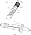
- the delivery system further includes a control handle 30 and two bending adjustment handles 40.
- control handle 30 is connected to the proximal end of the support tube 12 and can drive the support tube 12 to move axially, thereby driving the capsule chamber 23 to move.
- the control handle 30 includes a first stroke assembly 34 configured to control an axial movement distance of the support tube 11.
- the control handle 30 is arranged along the axial direction of the inner core 11.
- the control handle 30 includes a handle main body sleeve 31, a control sleeve 32, and a control sliding block 33.
- the first stroke assembly 34 includes a first stroke sleeve 341 and a first stroke indicating member 342.
- the handle main body sleeve 31 is provided with an axial control slideway.
- An inner side of the control sleeve 32 drives the control sliding block 33 to slide along the axial control slideway through threaded fit.
- the handle main body sleeve 31 is of a cylindrical structure
- the control sleeve 32 is sleeved on the outer side surface of the handle main body sleeve 31 and can rotate coaxially outside the handle main body sleeve 31.
- the inner side of the control sleeve 32 has internal threads. Both sides of the axial control slideway are provided with guide grooves.
- the control sliding block 33 is axially mounted on the axial control slideway and an outer side thereof protrudes from the guide groove to fit with the internal threads of the control sleeve 32 When the control sleeve 32 rotates, the control sliding block 33 is driven to slide axially.
- the first stroke sleeve 341 is coaxially and fixedly sleeved on the outer side of the control sleeve 32
- the first stroke sleeve 341 is provided with a first stroke slideway.
- the outer side of the control sleeve 32 has external threads.
- the first stroke indicating member 342 fits with the external threads of the control sleeve 32. When the control sleeve 32 rotates, the first stroke indicating member 342 slides on the first stroke slideway.
- the specifications of the threads on two sides of the control sleeve 32 are set to be the same or preset as prescribed.
- a stroke scale configured to indicate a moving distance is provided on the first stroke slideway, so that a sliding distance of the control sliding block 23 can be known through a sliding distance of the first stroke indicating member 342 on the first stroke slideway, thereby accurately controlling the axial movement distance of the support tube 12.
- thread driving adjustment accuracy thereof is high, stopping and locking at any time throughout the process can be realized, and the release process of the valve stent can be accurately monitored to reduce difficulty of release of the stent.
- the control handle 30 further includes a dismounting member 35 detachably mounted at a proximal end of the handle main body sleeve 31 and connected to a proximal end of the limiting member 21.
- a dismounting member 35 detachably mounted at a proximal end of the handle main body sleeve 31 and connected to a proximal end of the limiting member 21.
- the two bending adjustment handles 40 are provided at a proximal end of the inner sheath tube 13 and a proximal end of the outer sheath tube 14, respectively. Corresponding distal ends of the inner sheath tube 13 and the outer sheath tube 14 are bent in the same plane or different planes through a traction wire 50.
- the bending adjustment handles 40 each includes a second stroke assembly 47 configured to control a bending curvature of corresponding inner sheath tube 13 or the outer sheath tube 14.
- a sheath is generally required to extend through an aortic arch after entering through a femoral artery, and the blood vessel here has a large bending angle and bends in the three-dimensional direction, which has high requirements for delivery of the heart valve stent. If only one bending sheath that may be bent in one plane is used, when entering the aortic arch, the sheath first bends in one plane and then bends to another plane through friction and guidance with the blood vascular wall. This manner also allows entry to the heart.
- the bending degree of the sheath can be directly fed back to the stroke control curvature, so that how much curvature the sheath needs to continue to bend can also be accurately performed through the stroke control. Therefore, in summary, when the sheath enters the aortic arch that has a large bending angle and bends in the three-dimensional direction, the double-layer bending adjustment and stroke control are very necessary, so that the sheath can quickly reach the heart through the aortic arch and the time is saved.
- the two bending adjustment handles 40 are sequentially arranged on a side of the control handle 30 adjacent to a distal end of an inner tube 10, and the bending adjustment handle 40 configured to adjust the inner sheath tube 13 is arranged closer to the control handle 20, so that the inner sheath tube 13 and the outer sheath tube 14 are bent, respectively.
- the bending adjustment handle 40 includes an axial portion a and a branch portion b, the axial portion a is arranged along an axial direction of the inner tube 10, the proximal ends of the inner sheath tube 13 and the outer sheath tube 14 are fixed to the axial portions of the corresponding bending adjustment handles 40, and the branch portion b forms an acute angle with the axial portion a.
- the axial portion a and the branch portion b form a certain angle, which effectively shortens an overall length of the delivery system.
- the second stroke assembly is arranged on the branch portion b.
- the bending of the branch portion b and the bending of the corresponding sheath belong to the same bending arc, so as to have an effect of guiding the bending.
- a linear stroke is transformed into bending curvature more smoothly, there will be no large bending action within a stroke, thereby the stability of the device.
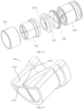
- the axial portion a includes an axial sleeve 41, a hemostatic valve 42 and a proximal fixing cover 43.
- the axial sleeve 41 is provided with an axial through hole.
- the proximal ends of the inner sheath tube 13 and the outer sheath tube 14 are inserted from the distal end of the corresponding axial sleeve 41 and are locked.
- the axial sleeve 41 is provided with a lateral line hole 411 corresponding to the branch portion b.
- the hemostatic valve 42 is arranged at the axial sleeve 41 adjacent to a proximal end thereof and is provided with an elastically contractible hemostatic channel.
- the proximal fixing cover 43 is fixed to the proximal end of the axial sleeve 41 and is provided with a pipeline through hole.
- the hemostatic valve 42 is mainly configured to prevent blood from leaking through the sheath under blood pressure when the sheath enters the blood vessel.
- the hemostatic valve 42 includes at least one valve plate set 420.
- the hemostatic valve 42 includes two valve plate sets 420 arranged in the axial direction.
- the valve plate set 420 includes a valve plate sleeve 421 and a first valve plate 422, a second valve plate 423, and a third valve plate 424 that are coaxially s arranged in sequence from the proximal end to the distal end.
- a first hole is formed in a middle portion of the first valve plate 422.
- Non-penetrating notches are formed on two sides of the first valve plate 422, and the non-penetrating notches on the two sides are staggered.
- cross grooves are formed on two sides of the first valve plate 422, the two cross grooves are staggered by 45 degrees, and the middle portion of the first valve plate 422 can be effectively axially raised towards the two sides.
- the middle portion of the second valve plate 423 protrudes to the distal end and is provided with a second hole at a central position thereof.
- An annular step 4231 is formed on a side of the second valve plate 423 adjacent to the third valve plate 424.
- the third valve plate 424 includes an elastic cylinder 4241 and two elastic flaps 4242.
- the elastic flaps 4242 are connected to an inner wall of the elastic cylinder 4241, Distal ends of the two elastic flaps 4242 form a flap opening that can be opened and closed.
- the distal ends of the elastic flaps 4242 and the inner wall of the elastic cylinder 4241 are provided with elastic support ribs 4243 configured to elastically close the flap opening.
- the annular step 4231 is embedded in a proximal opening of the elastic cylinder 4241.
- the valve plate sleeve 421 is a cylindrical member.
- the elastic cylinder 4241 is partially or wholly embedded in the valve plate sleeve 421.
- the first hole, the second hole and the flap opening form the hemostatic channel.
- the branch portion b includes a branch main body 44, a bending adjustment sliding block 45, and a bending adjustment sleeve 46.
- the second stroke assembly 47 includes a second stroke sleeve 471 and a second stroke indicating member 472.
- the branch main body 44 includes an axial fixing tube 441 and a guide tube 442 that are in communication with each other.
- the axial fixing tube 441 is coaxially fixed to an outer side of the axial sleeve 41.
- the guide tube 442 is arranged corresponding to the lateral line hole.
- the guide tube 442 extends towards the proximal end and forms a predetermined acute angle with the axial fixing tube 441An interior of the guide tube 442 is provided with a bending adjustment guide slideway along an axial direction thereof.
- a proximal end of the traction wire 50 is fixed to the bending adjustment sliding block 45.
- the principle of bending adjustment is that the bending adjustment sliding block 45 is driven by the bending adjustment sleeve 46 to move in a straight line and then the proximal end of the traction wire is moved to pull the distal end of the corresponding inner sheath tube 13 or outer sheath tube 14 to bend.
- connection between the bending adjustment sliding block 45 and the bending adjustment sleeve 46 is similar to that between the control sleeve 32 and the control sliding block 33. That is, an inner side of the bending adjustment sleeve 46 drives the bending adjustment sliding block 45 to slide along the bending adjustment guide slideway through threaded fit.
- the second stroke sleeve 471 is fixedly sleeved on the outer side of the bending adjustment sleeve 46.
- the second stroke sleeve 471 is provided with a second stroke slideway.
- the outer side of the bending adjustment sleeve 46 drives the second stroke indicating member 472 to slide along the second stroke slideway through threaded fit.
- the second stroke indicating member 472 may make judgment according to an observed movement distance or a movement thread distance, or a specific stroke scale may be provided on a surface of the second stroke sleeve 471 for judgment, so as to adjust a proximal motion distance of the traction wire, thereby achieving accurate control of bending curvature of the inner sheath tube 13 or the outer sheath tube 14.
- the support tube 12 is driven by the control handle 30 to move axially.
- the two bending adjustment handles 40 drive the distal ends of the inner sheath tube 13 and the outer sheath tube 14 to bend through the corresponding traction wire 50.
- the control handle 20 is provided with the first stroke assembly 24 to accurately control the axial movement distance of the support tube 11, and the bending adjustment handle 40 is provided with the second stroke assembly 47 to control bending curvature of the sheath, thereby bettering controlling bending and release of the artificial valve.
Landscapes
- Health & Medical Sciences (AREA)
- Cardiology (AREA)
- Oral & Maxillofacial Surgery (AREA)
- Transplantation (AREA)
- Engineering & Computer Science (AREA)
- Biomedical Technology (AREA)
- Heart & Thoracic Surgery (AREA)
- Vascular Medicine (AREA)
- Life Sciences & Earth Sciences (AREA)
- Animal Behavior & Ethology (AREA)
- General Health & Medical Sciences (AREA)
- Public Health (AREA)
- Veterinary Medicine (AREA)
- Prostheses (AREA)
Applications Claiming Priority (5)
| Application Number | Priority Date | Filing Date | Title |
|---|---|---|---|
| CN202210474024.5A CN116407363B (zh) | 2022-04-29 | 2022-04-29 | 一种介入式心脏瓣膜支架的输送装置及输送系统 |
| CN202210896187.2A CN117045396A (zh) | 2022-07-27 | 2022-07-27 | 一种用于经导管主动脉瓣置换的双层调弯鞘 |
| CN202310358575.XA CN117045397B (zh) | 2023-03-31 | 2023-03-31 | 一种可变径胶囊腔的主动脉瓣膜输送系统 |
| CN202310500068.5A CN116616957A (zh) | 2023-04-26 | 2023-04-26 | 一种主动脉瓣膜输送系统 |
| PCT/CN2023/091868 WO2023208232A1 (zh) | 2022-04-29 | 2023-04-28 | 一种介入式心脏瓣膜支架的输送系统 |
Publications (2)
| Publication Number | Publication Date |
|---|---|
| EP4516264A1 true EP4516264A1 (de) | 2025-03-05 |
| EP4516264A4 EP4516264A4 (de) | 2025-08-13 |
Family
ID=88517923
Family Applications (1)
| Application Number | Title | Priority Date | Filing Date |
|---|---|---|---|
| EP23795664.4A Pending EP4516264A4 (de) | 2022-04-29 | 2023-04-28 | Freisetzungssystem für interventionellen herzklappenstent |
Country Status (3)
| Country | Link |
|---|---|
| EP (1) | EP4516264A4 (de) |
| JP (1) | JP2025514441A (de) |
| WO (1) | WO2023208232A1 (de) |
Families Citing this family (2)
| Publication number | Priority date | Publication date | Assignee | Title |
|---|---|---|---|---|
| CN118285965A (zh) * | 2024-04-26 | 2024-07-05 | 金仕生物科技(常熟)有限公司 | 瓣膜输送系统 |
| CN119279731A (zh) * | 2024-12-11 | 2025-01-10 | 科瑞迈吉(北京)医疗科技有限公司 | 植入物捕获取出装置 |
Family Cites Families (11)
| Publication number | Priority date | Publication date | Assignee | Title |
|---|---|---|---|---|
| US8568472B2 (en) * | 2006-09-08 | 2013-10-29 | Edwards Lifesciences Corporation | Integrated heart valve delivery system |
| US8652202B2 (en) * | 2008-08-22 | 2014-02-18 | Edwards Lifesciences Corporation | Prosthetic heart valve and delivery apparatus |
| US8475523B2 (en) * | 2010-02-17 | 2013-07-02 | Medtronic, Inc. | Distal tip assembly for a heart valve delivery catheter |
| US10856978B2 (en) * | 2010-05-20 | 2020-12-08 | Jenavalve Technology, Inc. | Catheter system |
| US9414915B2 (en) * | 2010-09-24 | 2016-08-16 | Symetis Sa | Stent valve, delivery apparatus and method therefor |
| CN108601645B (zh) * | 2015-12-15 | 2021-02-26 | 内奥瓦斯克迪亚拉公司 | 经中隔递送系统 |
| US10786651B2 (en) * | 2017-03-07 | 2020-09-29 | Talon Medical, LLC | Steerable guide catheter |
| US10433961B2 (en) * | 2017-04-18 | 2019-10-08 | Twelve, Inc. | Delivery systems with tethers for prosthetic heart valve devices and associated methods |
| CN111714252B (zh) * | 2020-07-17 | 2025-05-16 | 上海翰凌医疗器械有限公司 | 一种瓣膜输送装置 |
| JP2023540505A (ja) * | 2020-09-03 | 2023-09-25 | インキュービー8・メディカル・テクノロジーズ・リミテッド・ライアビリティ・カンパニー | 人工心臓弁のためのデリバリーシステムおよび方法 |
| CN113796987B (zh) * | 2020-10-12 | 2025-04-08 | 宁波健世科技股份有限公司 | 一种可缓冲释放植入器械的输送系统 |
-
2023
- 2023-04-28 EP EP23795664.4A patent/EP4516264A4/de active Pending
- 2023-04-28 WO PCT/CN2023/091868 patent/WO2023208232A1/zh not_active Ceased
- 2023-04-28 JP JP2024564528A patent/JP2025514441A/ja active Pending
Also Published As
| Publication number | Publication date |
|---|---|
| WO2023208232A1 (zh) | 2023-11-02 |
| EP4516264A4 (de) | 2025-08-13 |
| JP2025514441A (ja) | 2025-05-02 |
Similar Documents
| Publication | Publication Date | Title |
|---|---|---|
| US11712337B2 (en) | Delivery systems and methods of implantation for prosthetic heart valves | |
| US10828158B2 (en) | Catheter shaft construction for TAVR delivery systems | |
| EP4516264A1 (de) | Freisetzungssystem für interventionellen herzklappenstent | |
| US20210361425A1 (en) | Delivery Systems And Methods Of Implantation For Prosthetic Heart Valves | |
| US10603166B2 (en) | Delivery device having a curved shaft and a straightening member for transcatheter aortic valve implantation | |
| US8740976B2 (en) | Transcatheter prosthetic heart valve delivery system with flush report | |
| EP3603575B1 (de) | Transkatheterherzklappenprothesenfreisetzungssystem mit gesteuerter expansion einer herzklappenprothese | |
| KR20200038312A (ko) | 능동 도입기 외장 시스템 | |
| EP3590470A1 (de) | Transkatheterfreisetzungssystem für kontrollierte expansion und kontraktion einer herzklappenprothese | |
| EP4147741A1 (de) | Steuergriff, biegesteuerungslinie und implantateinführungsvorrichtung | |
| EP4410242A1 (de) | Verankerungsvorrichtungen für künstliche herzklappe und künstliches herzklappensystem | |
| US20250000651A1 (en) | Cardiac Valve Loading Devices and Systems | |
| CN117481871A (zh) | 一种人工瓣膜输送装置及系统 | |
| CN216754729U (zh) | 经股瓣膜修复用输送器的输送系统 | |
| CN115363826A (zh) | 一种人工瓣膜输送装置及系统 | |
| CN216257640U (zh) | 一种植入假体输送系统上的可控释放装置 | |
| CN116407363A (zh) | 一种介入式心脏瓣膜支架的输送装置及输送系统 | |
| EP4017379B1 (de) | Ankermit anpassbarer länge | |
| CN221451453U (zh) | 一种导丝跨瓣器及导丝跨瓣组件 | |
| WO2025118705A1 (zh) | 一种人工瓣膜输送装置及系统 | |
| CN117045397B (zh) | 一种可变径胶囊腔的主动脉瓣膜输送系统 | |
| CN218045225U (zh) | 一种锚钉装置和锚钉输送器 | |
| EP4134048B1 (de) | Ladewerkzeug und system für implantat | |
| CN202069719U (zh) | 一种经心尖植入瓣膜的瓣膜输送系统 | |
| CN216570345U (zh) | 一种瓣膜修复系统 |
Legal Events
| Date | Code | Title | Description |
|---|---|---|---|
| STAA | Information on the status of an ep patent application or granted ep patent |
Free format text: STATUS: THE INTERNATIONAL PUBLICATION HAS BEEN MADE |
|
| PUAI | Public reference made under article 153(3) epc to a published international application that has entered the european phase |
Free format text: ORIGINAL CODE: 0009012 |
|
| STAA | Information on the status of an ep patent application or granted ep patent |
Free format text: STATUS: REQUEST FOR EXAMINATION WAS MADE |
|
| 17P | Request for examination filed |
Effective date: 20241126 |
|
| AK | Designated contracting states |
Kind code of ref document: A1 Designated state(s): AL AT BE BG CH CY CZ DE DK EE ES FI FR GB GR HR HU IE IS IT LI LT LU LV MC ME MK MT NL NO PL PT RO RS SE SI SK SM TR |
|
| DAV | Request for validation of the european patent (deleted) | ||
| DAX | Request for extension of the european patent (deleted) | ||
| A4 | Supplementary search report drawn up and despatched |
Effective date: 20250714 |
|
| RIC1 | Information provided on ipc code assigned before grant |
Ipc: A61F 2/24 20060101AFI20250708BHEP |