EP4516254A1 - Verfahren zur gestaltung einer patientenindividuellen führung sowie programm und server dafür - Google Patents
Verfahren zur gestaltung einer patientenindividuellen führung sowie programm und server dafür Download PDFInfo
- Publication number
- EP4516254A1 EP4516254A1 EP24793961.4A EP24793961A EP4516254A1 EP 4516254 A1 EP4516254 A1 EP 4516254A1 EP 24793961 A EP24793961 A EP 24793961A EP 4516254 A1 EP4516254 A1 EP 4516254A1
- Authority
- EP
- European Patent Office
- Prior art keywords
- base plate
- center pin
- guidance
- operator
- patient
- Prior art date
- Legal status (The legal status is an assumption and is not a legal conclusion. Google has not performed a legal analysis and makes no representation as to the accuracy of the status listed.)
- Pending
Links
Images


Classifications
-
- A—HUMAN NECESSITIES
- A61—MEDICAL OR VETERINARY SCIENCE; HYGIENE
- A61B—DIAGNOSIS; SURGERY; IDENTIFICATION
- A61B34/00—Computer-aided surgery; Manipulators or robots specially adapted for use in surgery
- A61B34/10—Computer-aided planning, simulation or modelling of surgical operations
-
- A—HUMAN NECESSITIES
- A61—MEDICAL OR VETERINARY SCIENCE; HYGIENE
- A61B—DIAGNOSIS; SURGERY; IDENTIFICATION
- A61B17/00—Surgical instruments, devices or methods
- A61B17/16—Instruments for performing osteoclasis; Drills or chisels for bones; Trepans
- A61B17/17—Guides or aligning means for drills, mills, pins or wires
- A61B17/1739—Guides or aligning means for drills, mills, pins or wires specially adapted for particular parts of the body
- A61B17/1778—Guides or aligning means for drills, mills, pins or wires specially adapted for particular parts of the body for the shoulder
-
- G—PHYSICS
- G06—COMPUTING OR CALCULATING; COUNTING
- G06F—ELECTRIC DIGITAL DATA PROCESSING
- G06F30/00—Computer-aided design [CAD]
- G06F30/20—Design optimisation, verification or simulation
-
- A—HUMAN NECESSITIES
- A61—MEDICAL OR VETERINARY SCIENCE; HYGIENE
- A61B—DIAGNOSIS; SURGERY; IDENTIFICATION
- A61B17/00—Surgical instruments, devices or methods
- A61B17/56—Surgical instruments or methods for treatment of bones or joints; Devices specially adapted therefor
- A61B17/58—Surgical instruments or methods for treatment of bones or joints; Devices specially adapted therefor for osteosynthesis, e.g. bone plates, screws or setting implements
- A61B17/68—Internal fixation devices, including fasteners and spinal fixators, even if a part thereof projects from the skin
- A61B17/84—Fasteners therefor or fasteners being internal fixation devices
- A61B17/846—Nails or pins, i.e. anchors without movable parts, holding by friction only, with or without structured surface
-
- A—HUMAN NECESSITIES
- A61—MEDICAL OR VETERINARY SCIENCE; HYGIENE
- A61B—DIAGNOSIS; SURGERY; IDENTIFICATION
- A61B17/00—Surgical instruments, devices or methods
- A61B17/56—Surgical instruments or methods for treatment of bones or joints; Devices specially adapted therefor
- A61B2017/568—Surgical instruments or methods for treatment of bones or joints; Devices specially adapted therefor produced with shape and dimensions specific for an individual patient
-
- A—HUMAN NECESSITIES
- A61—MEDICAL OR VETERINARY SCIENCE; HYGIENE
- A61B—DIAGNOSIS; SURGERY; IDENTIFICATION
- A61B34/00—Computer-aided surgery; Manipulators or robots specially adapted for use in surgery
- A61B34/10—Computer-aided planning, simulation or modelling of surgical operations
- A61B2034/101—Computer-aided simulation of surgical operations
- A61B2034/102—Modelling of surgical devices, implants or prosthesis
-
- A—HUMAN NECESSITIES
- A61—MEDICAL OR VETERINARY SCIENCE; HYGIENE
- A61B—DIAGNOSIS; SURGERY; IDENTIFICATION
- A61B34/00—Computer-aided surgery; Manipulators or robots specially adapted for use in surgery
- A61B34/10—Computer-aided planning, simulation or modelling of surgical operations
- A61B2034/101—Computer-aided simulation of surgical operations
- A61B2034/105—Modelling of the patient, e.g. for ligaments or bones
-
- A—HUMAN NECESSITIES
- A61—MEDICAL OR VETERINARY SCIENCE; HYGIENE
- A61B—DIAGNOSIS; SURGERY; IDENTIFICATION
- A61B34/00—Computer-aided surgery; Manipulators or robots specially adapted for use in surgery
- A61B34/10—Computer-aided planning, simulation or modelling of surgical operations
- A61B2034/107—Visualisation of planned trajectories or target regions
-
- A—HUMAN NECESSITIES
- A61—MEDICAL OR VETERINARY SCIENCE; HYGIENE
- A61F—FILTERS IMPLANTABLE INTO BLOOD VESSELS; PROSTHESES; DEVICES PROVIDING PATENCY TO, OR PREVENTING COLLAPSING OF, TUBULAR STRUCTURES OF THE BODY, e.g. STENTS; ORTHOPAEDIC, NURSING OR CONTRACEPTIVE DEVICES; FOMENTATION; TREATMENT OR PROTECTION OF EYES OR EARS; BANDAGES, DRESSINGS OR ABSORBENT PADS; FIRST-AID KITS
- A61F2/00—Filters implantable into blood vessels; Prostheses, i.e. artificial substitutes or replacements for parts of the body; Appliances for connecting them with the body; Devices providing patency to, or preventing collapsing of, tubular structures of the body, e.g. stents
- A61F2/02—Prostheses implantable into the body
- A61F2/30—Joints
- A61F2/40—Joints for shoulders
- A61F2/4081—Glenoid components, e.g. cups
Definitions
- the displaying of the screen in which the base plate is installed according to the position and direction of the center pin determined by the operator may include: displaying at least one base plate on a screen; and displaying a base plate selected by the operator among the at least one base plate to be overlaid on the first skeleton image plane in alignment with the center point.
- a server for designing a guidance specific to a patient including: a memory and a processor, wherein the processor is configured to, in connection with the memory, specify a first skeletal image plane in which a base plate is to be installed on a skeleton of a patient in which an affected area is located; display a normal vector N of the first skeletal image plane together with the skeleton of the patient in three dimensions (3D); provide an operator with an intersection of the normal vector and the first skeletal image plane such that the operator arbitrarily moves the intersection or rotates the normal vector based on the intersection to determine a direction of a center pin; install the base plate according to a position (a center point) and the direction of the center pin determined by the operator; and calculate a rotation angle and depth of peripheral screws to be installed on the base plate.
- the processor is configured to, in connection with the memory, specify a first skeletal image plane in which a base plate is to be installed on a skeleton of a patient in which an affected area is located; display a normal vector N of the first
- the processor may be configured to receive, from the operator, an input to move the center point in an arbitrary direction or an input to change a rotation angle of the center pin.
- the processor may be configured to further receive an input from the user other than the operator.
- the method disclosed herein is implement to provide a guidance that may allow a patient-specific fixation angle to be calculated such that an implant is correctly installed in a patient-specific position in an artificial joint replacement surgery, thereby reducing risks in an actual replacement surgery.
- the method disclosed herein is implement to design a guidance that may be intuitively identified in a glenoid, thereby controlling errors occurring due to environmental differences between a virtual three-dimensional space and a real space.
- the term “comprises” or “includes” and/or “comprising” or “including” means that one or more other components may not be further excluded unless context dictates otherwise.
- the term “part” or “module” refers to a unit for processing at least one function or operation that may be implemented in hardware, software, or a combination thereof.
- the expression, "at least one of a, b, and c,” should be understood as including only a, only b, only c, both a and b, both a and c, both b and c, or all of a, b, and c.
- transmitting or “sending” a signal, messages, or information to a component indicates the final destination of the signal, message, or information and does not mean a direct destination. The same is true for the "reception” of a signal or information.
- that two or more pieces of data or information are "related” means that if one data (or information) is obtained, at least a portion of the other data (or information) may be obtained based thereon.
- a first element could be termed a second element or a third element without departing from the scope of the present invention.
- FIG. 1 is a flowchart for describing a design method according to an embodiment.
- the method shown in FIG. 1 may be performed by an electronic apparatus 100 described with reference to FIG. 8 .
- the method of designing a guidance is described as being divided into a plurality of operations, but at least some of the operations may be performed in a reverse order, performed in combination with other operations, omitted, further divided into a larger number of sub-operations, or combined into a smaller of operations.
- some operations described herein may be added.
- a method of designing a guidance specific to a patient includes displaying, with respect to a skeleton of a patient to be subject to an artificial joint replacement, a three-dimensional (3D) view of a skeletal area of the patient in which an implant is to be installed (S10).
- the "patient's skeleton” may be specified as the glenoid around the scapula.
- an area around the scapula is described as a specific embodiment of the patient's skeleton, but the disclosure is not limited thereto.
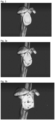
- FIG. 2 shows a first skeletal image in 3D.
- FIG. 2 shows a screen showing the glenoid facing forward, but the screen may be adjusted in all directions, forward, backward, leftward, and rightward directions, at 360 degrees, allowing the patient's skeletal area to be viewed.
- the user designates a plurality of reference points for positioning a base plate arbitrarily by the user or automatically by a program (S20). Referring to FIG. 3A , the user may arbitrarily designate four points p1 to p4 on the outermost edge of the glenoid plane.
- the program may calculate the position and direction of a center pin CP (S30 in FIG. 1 and FIG. 3B ).
- the position of the center pin CP corresponds to a crossing point of a straight line p 1 , p 3 connecting P1 and P3 and a straight line p 2 , p 4 connecting P2 and P4, and the direction of the center pin CP is a normal vector N of a plane obtained by p 1 , p 3 and p 2 , p 4 .
- the normal vector is indicated by a red thick solid line.
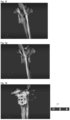
- FIGS. 3C and 3D show the normal vector N of the center pin CP on a 3D screen, and the user may visually check whether the center pin of the scapula according to the embodiment is most deeply inserted into the scapula. That is, FIG. 3C is a screen showing the side and rear aspect of the scapula as seen from the back of the human body, and it can be visually confirmed that the normal vector N of the center pin CP is not directed toward a deep position of the scapula. Therefore, when the center pin is positioned in the direction of the normal vector N, the center pin is not securely fixed, so there is a need to reposition the corresponding direction. That is, referring to FIG.
- FIGS. 3E and 3F are user-customized screens showing adjustment of direction of the center pin CP with respect to the normal vector N according to an embodiment.
- FIGS. 3E and 3F show rotation of the center pin CP in some direction from the normal vector N, moving the center pin CP toward the main axis of the scapula.
- FIG. 3E is a screen in which the center pin CP from FIG. 3D is rotated about the x-axis direction, and thus is aligned in parallel with the most protruding part of the main axis of the scapula.
- FIG. 3F is a screen showing that the center pin CP rotated about the x-axis direction in FIG. 3E is rotated about the y-axis direction, and thus moved onto the main axis of the scapula.
- the user may set a desired position moved relative to the center point of the center pin CP, which corresponds to the crossing point of the straight line p 1 , p 3 connecting P1 and P3 and the straight line p 2 , p 4 connecting P2 and P4, in each axis direction as a center point.
- the user may check the 3D skeleton area displayed on the screen, visually confirm a position which is deep enough for the center pin CP to be most securely inserted, and select and determine the rotation angle of the center pin CP for each axis or the moving distance of the center pin CP.
- the program may not only allow the user to arbitrarily adjust the direction and angle of the center pin CP, but also automatically move the center pin CP to the position in which the center pin CP may be most securely inserted in the scapula. Therefore, in FIG. 3G , it can be visually confirmed that the center pin CP is rotated to some degree about the x and y axes from the initial direction of the normal vector N and thus moved toward the deepest part of the scapula.
- the program displays a base plate selection screen 500 on one side of the screen such that the user may select a base plate to be used.
- the base plate selection screen 500 may display a plurality of base plate shapes stored in the program.
- FIG. 3I is a 3D screen showing screws including first to fourth screws sc1 to sc4 to fix the base plate BP, which is viewed from the side and rear aspect of the shoulder joint.
- FIG. 3J is a 3D screen after the angles of the plurality of screws to be used in the base plate are calculated.
- a peripheral screw setting display unit 510 at the lower right side shows modified x and y axis rotation angles and depths of the first to fourth screws sc1 to sc4.
- Operation 1 a ray L is emitted from each point p1 to p4 of the first to fourth screws in the direction of the normal vector N, to find a triangle crossing the ray L.
- n tj denotes a normal vector of a triangle t j
- n tj t L1j ⁇ t L2j (outer product)
- Operation 1-2 when N ⁇ n tj (inner product) ⁇ 0, an intersection p x of a plane containing the triangle t j and the ray L is calculated.
- p x p i + n tj ⁇ p j1 ⁇ p i / n tj ⁇ p y ⁇ p i * p y ⁇ p i
- Operation 1-3 when the intersection p x having the same sign in Equation 2 to Equation 4, the distance d between P i and P x , which is a crossing point P x with the ray L, is calculated.
- Operation 2 with respect to P i (P 1 to P 4 ), the ray L is rotated about the x-axis from -15° to +15° in 1°increments, and for each rotation of 1°about the x-axis, the ray L is rotated about the Y-axis from -15° to +15° in 1° increments, and operations 1-1 to 1-3 are repeated for each rotation angle (r x , r y ).
- the rotation angle and depth of each peripheral screw for the maximum depth (d) value may be determined as max ⁇ d:r x ,r y ⁇ .
- FIG. 4 describes a method of generating a guidance bridge of the center pin CP according to an embodiment after calculating the angle of the peripheral screw in a peripheral screw screen portion of FIG. 3 .
- a screen of the position and angle of the center pin CP is displayed (S60). That is, as shown in FIG. 4A, it is possible to show the position in which the center pin CP is placed in the glenoid. In this case, the position and angle of the center pin CP are determined as described above with reference to FIGS. 2 and 3 , and thus details thereof is omitted in the following description.
- a reference point for a center pin guidance is designated arbitrarily by a user or in an automatic manner, and the designated reference point is displayed (S70). Specifically, a case in which the user arbitrarily designates a reference point RF of a center pin guidance may be shown in FIG. 5B .
- a center pin guidance bridge is displayed such that center pin guidance bridge is installed at the reference point (S80).
- S80 reference point
- the user may partially adjust the positions of the reference points with respect to the center pin guidance bridge installed at the position of the designated reference points RF1 to RF3.
- the user may arbitrarily adjust the center pin guidance bridge (S90).
- FIG. 5D it can be seen that the position of the first reference point RF1 may be rotated counterclockwise on the glenoid to a "first reference point RF1'" Therefore, in FIG. 5E , the final center pin guidance bridge is shown as a 3D shape, and the program according to an embodiment displays a 3D shape of the final center pin guidance CPG as shown in FIG. 5F (S100).
- the user visually adjusts the transparency of the guidance, the center pin, the peripheral screws, the scapula, and the like for the user to easily select and display the 3D image of each individual component.
- FIG. 7A is a screen showing a base plate BP placed on a glenoid according to an embodiment.
- FIG. 7B is a screen showing a peripheral screw guidance (a peripheral guidance) that facilitates installation of peripheral screws on the base plate BP according to an embodiment.
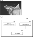
- the electronic apparatus 100 may include an input/output interface 101, a memory 103, and a processor 105.
- the electronic apparatus 100 may be connected to an external server or database through a transceiver or communication interface, and exchange data.
- the processor 105 may, in connection with the memory 103, specify a skeletal image on which a base plate is to be installed, determine the position and direction of a center point CP of the base plate, visually display the determined position and direction in 3D dimensions for the user to arbitrarily adjust the determined position and direction, store information about the angle adjusted by the user to generate a center point guidance, calculate the angles of peripheral screws according to the determined position and direction of the center point, and generate a peripheral screw guidance at the calculated peripheral screw angles and display the peripheral screw guidance separately or to be overlaid on the skeletal image.
- the electronic apparatus 100 shown in FIG. 8 includes only components related to the disclosed embodiment. Accordingly, those skilled in the art may understand that other general-purpose components may be included in addition to the components shown in FIG. 8 .
- the system for providing a collaborative service may further include a plurality of operator apparatuses or user apparatuses similar to the electronic apparatus 100 shown in FIG. 8 , as well as the server. Therefore, according to an embodiment, the system for providing a collaborative service may further include a network for supporting information transmission and reception between at least a part of the operator apparatuses or user apparatuses for a collaborative service between users and operators.
- the embodiments may be represented by functional block configurations and various processing operations. These functional blocks may be implemented with any number of hardware and/or software configurations that perform particular functions. For example, the embodiments may adopt integrated circuit configurations such as memory, processing, logic, look-up tables, etc., which may perform various functions by control of one or more microprocessors or by other control devices. Similar to the way in which components may be implemented in software programming or software components, the present embodiments may be implemented in a variety of ways, including C, C ++, Java, an assembler, python, and the like. Functional aspects may be implemented with algorithms running on one or more processors. In addition, the present embodiment may employ conventional techniques for electronic environment setting, signal processing, and/or data processing. Terms such as “mechanism”, “element”, “means”, “configuration” may be used broadly and are not limited to mechanical and physical configurations. The term may include the meaning of a series of routines of software in conjunction with a processor or the like.
Landscapes
- Engineering & Computer Science (AREA)
- Health & Medical Sciences (AREA)
- Life Sciences & Earth Sciences (AREA)
- Surgery (AREA)
- Theoretical Computer Science (AREA)
- Physics & Mathematics (AREA)
- Animal Behavior & Ethology (AREA)
- Veterinary Medicine (AREA)
- Biomedical Technology (AREA)
- Heart & Thoracic Surgery (AREA)
- Medical Informatics (AREA)
- Molecular Biology (AREA)
- Nuclear Medicine, Radiotherapy & Molecular Imaging (AREA)
- General Health & Medical Sciences (AREA)
- Public Health (AREA)
- Robotics (AREA)
- Computer Hardware Design (AREA)
- Evolutionary Computation (AREA)
- Geometry (AREA)
- General Engineering & Computer Science (AREA)
- General Physics & Mathematics (AREA)
- Orthopedic Medicine & Surgery (AREA)
- Oral & Maxillofacial Surgery (AREA)
- Dentistry (AREA)
- Processing Or Creating Images (AREA)
Applications Claiming Priority (2)
| Application Number | Priority Date | Filing Date | Title |
|---|---|---|---|
| KR1020230090210A KR102624485B1 (ko) | 2023-07-12 | 2023-07-12 | 환자 맞춤형 가이던스를 설계하는 방법, 이를 위한 프로그램 및 서버 |
| PCT/KR2024/009757 WO2025014250A1 (ko) | 2023-07-12 | 2024-07-09 | 환자 맞춤형 가이던스를 설계하는 방법, 이를 위한 프로그램 및 서버 |
Publications (2)
| Publication Number | Publication Date |
|---|---|
| EP4516254A1 true EP4516254A1 (de) | 2025-03-05 |
| EP4516254A4 EP4516254A4 (de) | 2026-03-11 |
Family
ID=89542781
Family Applications (1)
| Application Number | Title | Priority Date | Filing Date |
|---|---|---|---|
| EP24793961.4A Pending EP4516254A4 (de) | 2023-07-12 | 2024-07-09 | Verfahren zum entwurf einer patientenspezifischen führung sowie programm und server dafür |
Country Status (4)
| Country | Link |
|---|---|
| US (1) | US12070275B1 (de) |
| EP (1) | EP4516254A4 (de) |
| KR (1) | KR102624485B1 (de) |
| WO (1) | WO2025014250A1 (de) |
Families Citing this family (1)
| Publication number | Priority date | Publication date | Assignee | Title |
|---|---|---|---|---|
| KR102624485B1 (ko) * | 2023-07-12 | 2024-01-15 | (주)시안솔루션 | 환자 맞춤형 가이던스를 설계하는 방법, 이를 위한 프로그램 및 서버 |
Family Cites Families (8)
| Publication number | Priority date | Publication date | Assignee | Title |
|---|---|---|---|---|
| KR20110087220A (ko) | 2010-01-25 | 2011-08-02 | 주식회사 나노엔텍 | 의료서비스 제공서버 및 의료서비스 제공방법 |
| CN103702630A (zh) * | 2011-06-03 | 2014-04-02 | 史密夫和内修有限公司 | 包括患者匹配的特征的假体引导件 |
| US10543100B2 (en) * | 2012-03-28 | 2020-01-28 | Zimmer, Inc. | Glenoid implant surgery using patient specific instrumentation |
| US11166733B2 (en) * | 2017-07-11 | 2021-11-09 | Howmedica Osteonics Corp. | Guides and instruments for improving accuracy of glenoid implant placement |
| KR101981055B1 (ko) * | 2017-08-31 | 2019-05-23 | 주식회사 코렌텍 | 환자 맞춤형 수술기기 제조 시스템 및 그 방법 |
| WO2019245848A1 (en) * | 2018-06-19 | 2019-12-26 | Tornier, Inc. | Mixed-reality surgical system with physical markers for registration of virtual models |
| KR20200117118A (ko) | 2019-04-03 | 2020-10-14 | 주식회사 알파이브코리아 | 최적화된 의료 서비스 제공 방법 및 의료 서비스 제공 시스템 |
| KR102624485B1 (ko) * | 2023-07-12 | 2024-01-15 | (주)시안솔루션 | 환자 맞춤형 가이던스를 설계하는 방법, 이를 위한 프로그램 및 서버 |
-
2023
- 2023-07-12 KR KR1020230090210A patent/KR102624485B1/ko active Active
-
2024
- 2024-01-18 US US18/416,546 patent/US12070275B1/en active Active
- 2024-07-09 EP EP24793961.4A patent/EP4516254A4/de active Pending
- 2024-07-09 WO PCT/KR2024/009757 patent/WO2025014250A1/ko active Pending
Also Published As
| Publication number | Publication date |
|---|---|
| WO2025014250A1 (ko) | 2025-01-16 |
| KR102624485B1 (ko) | 2024-01-15 |
| US12070275B1 (en) | 2024-08-27 |
| EP4516254A4 (de) | 2026-03-11 |
Similar Documents
| Publication | Publication Date | Title |
|---|---|---|
| US20240164839A1 (en) | Orthopedic Fixation Control And Manipulation | |
| US10881433B2 (en) | Software for use with deformity correction | |
| EP2421461B1 (de) | System zur beurteilung der relativen position eines implantats und eines knochens einer kreatur | |
| EP4003205B1 (de) | Positionierung einer kamera zum teilen der perspektive einer operationsstelle | |
| AU2021267483B2 (en) | Mixed reality-based screw trajectory guidance | |
| JP5054372B2 (ja) | 人工関節置換術支援装置およびそれを用いた人工関節置換術支援システム | |
| EP4516254A1 (de) | Verfahren zur gestaltung einer patientenindividuellen führung sowie programm und server dafür | |
| EP4125672B1 (de) | Gelenkerkennung für orthopädische fixierung | |
| AU2020245028B2 (en) | Orthopedic fixation control and visualization | |
| US11648035B2 (en) | Orthopedic fixation strut swapping | |
| US20240197401A1 (en) | Method for designing patient-specific implant and guidance, program and apparatus therefor | |
| US20250017655A1 (en) | Method of designing patient-specific implant and guidance, and program and apparatus therefor |
Legal Events
| Date | Code | Title | Description |
|---|---|---|---|
| STAA | Information on the status of an ep patent application or granted ep patent |
Free format text: STATUS: UNKNOWN |
|
| STAA | Information on the status of an ep patent application or granted ep patent |
Free format text: STATUS: THE INTERNATIONAL PUBLICATION HAS BEEN MADE |
|
| PUAI | Public reference made under article 153(3) epc to a published international application that has entered the european phase |
Free format text: ORIGINAL CODE: 0009012 |
|
| STAA | Information on the status of an ep patent application or granted ep patent |
Free format text: STATUS: REQUEST FOR EXAMINATION WAS MADE |
|
| 17P | Request for examination filed |
Effective date: 20241029 |
|
| AK | Designated contracting states |
Kind code of ref document: A1 Designated state(s): AL AT BE BG CH CY CZ DE DK EE ES FI FR GB GR HR HU IE IS IT LI LT LU LV MC ME MK MT NL NO PL PT RO RS SE SI SK SM TR |
|
| A4 | Supplementary search report drawn up and despatched |
Effective date: 20260205 |
|
| RIC1 | Information provided on ipc code assigned before grant |
Ipc: A61B 34/10 20160101AFI20260130BHEP Ipc: G06F 30/20 20200101ALI20260130BHEP Ipc: A61F 2/40 20060101ALI20260130BHEP |