EP4516088A1 - Greenhouse air humidity and/or temperature control - Google Patents
Greenhouse air humidity and/or temperature control Download PDFInfo
- Publication number
- EP4516088A1 EP4516088A1 EP24185125.2A EP24185125A EP4516088A1 EP 4516088 A1 EP4516088 A1 EP 4516088A1 EP 24185125 A EP24185125 A EP 24185125A EP 4516088 A1 EP4516088 A1 EP 4516088A1
- Authority
- EP
- European Patent Office
- Prior art keywords
- heat exchanger
- greenhouse
- air flow
- heat
- flow path
- Prior art date
- Legal status (The legal status is an assumption and is not a legal conclusion. Google has not performed a legal analysis and makes no representation as to the accuracy of the status listed.)
- Pending
Links
Images

Classifications
-
- B—PERFORMING OPERATIONS; TRANSPORTING
- B01—PHYSICAL OR CHEMICAL PROCESSES OR APPARATUS IN GENERAL
- B01D—SEPARATION
- B01D53/00—Separation of gases or vapours; Recovering vapours of volatile solvents from gases; Chemical or biological purification of waste gases, e.g. engine exhaust gases, smoke, fumes, flue gases, aerosols
- B01D53/30—Controlling by gas-analysis apparatus
-
- A—HUMAN NECESSITIES
- A01—AGRICULTURE; FORESTRY; ANIMAL HUSBANDRY; HUNTING; TRAPPING; FISHING
- A01G—HORTICULTURE; CULTIVATION OF VEGETABLES, FLOWERS, RICE, FRUIT, VINES, HOPS OR SEAWEED; FORESTRY; WATERING
- A01G9/00—Cultivation in receptacles, forcing-frames or greenhouses; Edging for beds, lawn or the like
- A01G9/24—Devices or systems for heating, ventilating, regulating temperature, illuminating, or watering, in greenhouses, forcing-frames, or the like
-
- A—HUMAN NECESSITIES
- A01—AGRICULTURE; FORESTRY; ANIMAL HUSBANDRY; HUNTING; TRAPPING; FISHING
- A01G—HORTICULTURE; CULTIVATION OF VEGETABLES, FLOWERS, RICE, FRUIT, VINES, HOPS OR SEAWEED; FORESTRY; WATERING
- A01G9/00—Cultivation in receptacles, forcing-frames or greenhouses; Edging for beds, lawn or the like
- A01G9/24—Devices or systems for heating, ventilating, regulating temperature, illuminating, or watering, in greenhouses, forcing-frames, or the like
- A01G9/246—Air-conditioning systems
-
- B—PERFORMING OPERATIONS; TRANSPORTING
- B01—PHYSICAL OR CHEMICAL PROCESSES OR APPARATUS IN GENERAL
- B01D—SEPARATION
- B01D53/00—Separation of gases or vapours; Recovering vapours of volatile solvents from gases; Chemical or biological purification of waste gases, e.g. engine exhaust gases, smoke, fumes, flue gases, aerosols
- B01D53/26—Drying gases or vapours
- B01D53/261—Drying gases or vapours by adsorption
-
- B—PERFORMING OPERATIONS; TRANSPORTING
- B01—PHYSICAL OR CHEMICAL PROCESSES OR APPARATUS IN GENERAL
- B01D—SEPARATION
- B01D53/00—Separation of gases or vapours; Recovering vapours of volatile solvents from gases; Chemical or biological purification of waste gases, e.g. engine exhaust gases, smoke, fumes, flue gases, aerosols
- B01D53/26—Drying gases or vapours
- B01D53/265—Drying gases or vapours by refrigeration (condensation)
-
- F—MECHANICAL ENGINEERING; LIGHTING; HEATING; WEAPONS; BLASTING
- F24—HEATING; RANGES; VENTILATING
- F24F—AIR-CONDITIONING; AIR-HUMIDIFICATION; VENTILATION; USE OF AIR CURRENTS FOR SCREENING
- F24F11/00—Control or safety arrangements
- F24F11/70—Control systems characterised by their outputs; Constructional details thereof
- F24F11/80—Control systems characterised by their outputs; Constructional details thereof for controlling the temperature of the supplied air
- F24F11/81—Control systems characterised by their outputs; Constructional details thereof for controlling the temperature of the supplied air by controlling the air supply to heat-exchangers or bypass channels
-
- F—MECHANICAL ENGINEERING; LIGHTING; HEATING; WEAPONS; BLASTING
- F24—HEATING; RANGES; VENTILATING
- F24F—AIR-CONDITIONING; AIR-HUMIDIFICATION; VENTILATION; USE OF AIR CURRENTS FOR SCREENING
- F24F12/00—Use of energy recovery systems in air conditioning, ventilation or screening
- F24F12/001—Use of energy recovery systems in air conditioning, ventilation or screening with heat-exchange between supplied and exhausted air
- F24F12/006—Use of energy recovery systems in air conditioning, ventilation or screening with heat-exchange between supplied and exhausted air using an air-to-air heat exchanger
-
- F—MECHANICAL ENGINEERING; LIGHTING; HEATING; WEAPONS; BLASTING
- F24—HEATING; RANGES; VENTILATING
- F24F—AIR-CONDITIONING; AIR-HUMIDIFICATION; VENTILATION; USE OF AIR CURRENTS FOR SCREENING
- F24F3/00—Air-conditioning systems in which conditioned primary air is supplied from one or more central stations to distributing units in the rooms or spaces where it may receive secondary treatment; Apparatus specially designed for such systems
- F24F3/12—Air-conditioning systems in which conditioned primary air is supplied from one or more central stations to distributing units in the rooms or spaces where it may receive secondary treatment; Apparatus specially designed for such systems characterised by the treatment of the air otherwise than by heating and cooling
- F24F3/14—Air-conditioning systems in which conditioned primary air is supplied from one or more central stations to distributing units in the rooms or spaces where it may receive secondary treatment; Apparatus specially designed for such systems characterised by the treatment of the air otherwise than by heating and cooling by humidification; by dehumidification
- F24F3/1411—Air-conditioning systems in which conditioned primary air is supplied from one or more central stations to distributing units in the rooms or spaces where it may receive secondary treatment; Apparatus specially designed for such systems characterised by the treatment of the air otherwise than by heating and cooling by humidification; by dehumidification by absorbing or adsorbing water, e.g. using an hygroscopic desiccant
-
- F—MECHANICAL ENGINEERING; LIGHTING; HEATING; WEAPONS; BLASTING
- F24—HEATING; RANGES; VENTILATING
- F24F—AIR-CONDITIONING; AIR-HUMIDIFICATION; VENTILATION; USE OF AIR CURRENTS FOR SCREENING
- F24F3/00—Air-conditioning systems in which conditioned primary air is supplied from one or more central stations to distributing units in the rooms or spaces where it may receive secondary treatment; Apparatus specially designed for such systems
- F24F3/12—Air-conditioning systems in which conditioned primary air is supplied from one or more central stations to distributing units in the rooms or spaces where it may receive secondary treatment; Apparatus specially designed for such systems characterised by the treatment of the air otherwise than by heating and cooling
- F24F3/14—Air-conditioning systems in which conditioned primary air is supplied from one or more central stations to distributing units in the rooms or spaces where it may receive secondary treatment; Apparatus specially designed for such systems characterised by the treatment of the air otherwise than by heating and cooling by humidification; by dehumidification
- F24F3/147—Air-conditioning systems in which conditioned primary air is supplied from one or more central stations to distributing units in the rooms or spaces where it may receive secondary treatment; Apparatus specially designed for such systems characterised by the treatment of the air otherwise than by heating and cooling by humidification; by dehumidification with both heat and humidity transfer between supplied and exhausted air
-
- B—PERFORMING OPERATIONS; TRANSPORTING
- B01—PHYSICAL OR CHEMICAL PROCESSES OR APPARATUS IN GENERAL
- B01D—SEPARATION
- B01D2257/00—Components to be removed
- B01D2257/80—Water
-
- B—PERFORMING OPERATIONS; TRANSPORTING
- B01—PHYSICAL OR CHEMICAL PROCESSES OR APPARATUS IN GENERAL
- B01D—SEPARATION
- B01D2258/00—Sources of waste gases
- B01D2258/06—Polluted air
-
- Y—GENERAL TAGGING OF NEW TECHNOLOGICAL DEVELOPMENTS; GENERAL TAGGING OF CROSS-SECTIONAL TECHNOLOGIES SPANNING OVER SEVERAL SECTIONS OF THE IPC; TECHNICAL SUBJECTS COVERED BY FORMER USPC CROSS-REFERENCE ART COLLECTIONS [XRACs] AND DIGESTS
- Y02—TECHNOLOGIES OR APPLICATIONS FOR MITIGATION OR ADAPTATION AGAINST CLIMATE CHANGE
- Y02A—TECHNOLOGIES FOR ADAPTATION TO CLIMATE CHANGE
- Y02A40/00—Adaptation technologies in agriculture, forestry, livestock or agroalimentary production
- Y02A40/10—Adaptation technologies in agriculture, forestry, livestock or agroalimentary production in agriculture
- Y02A40/25—Greenhouse technology, e.g. cooling systems therefor
Definitions
- the invention relates to a method and an arrangement for control of humidity and/or temperature of a greenhouse.
- Removal of excess moisture from a greenhouse is important for prevention of damage such as growth of mold and fungus, prevention of diseases caused by spread of bacteria and viruses, and controlled evaporation of moisture from the leaf surfaces of the plants to optimize their growth.
- Document WO 2017/062476 A1 describes a controlled and closed agricultural system having an enthalpy wheel and cooling coil.
- the cooling coil is positioned within a recirculating air duct, downstream of and in series with the enthalpy wheel.
- the cooling coil circulates a heat transfer fluid to remove additional heat from the recirculating air.
- a dehumidification system includes a desiccant, a primary heat exchanger, a secondary heat exchanger, three fans, and a burner.
- the first fan generates a carbon dioxide airflow through the primary heat exchanger and the secondary heat exchanger.
- the burner generates a flame into one end of the primary heat exchanger.
- the second fan generates an airflow that flows over the secondary heat exchanger, the primary heat exchanger and through a first portion of the desiccant.
- the third fan generates an air flow that flows through a second portion of the desiccant.
- the embodiments of the invention provide the significant advantage of efficient humidity and/or temperature control of a greenhouse.
- the condensation step is performed before the adsorption step. In this way, significant advantages can be obtained in terms of humidity reduction performance and energy savings when compared to systems where the adsorption phase is carried out before the condensation phase.
- the technical effect of the present invention when first performing the condensation step, is that the outside air becomes far more suitable for the subsequent adsorption step. That is, in the initial condensation step, the outside air can be heated to a relatively high temperature and to a low humidity, which is optimal for the subsequent adsorption step thereby resulting into more efficient reduction of humidity while also saving significant amount of energy during the process.
- the advantages of the present invention are especially notable in low temperatures of the outside air, such as in the temperature range -10 C to +10 C but perform also better in other temperature ranges when compared to systems first performing an adsorption phase.
- the important specific of the present invention is thus the behaviour of the outside air in the process. While first performing the condensation phase, the relative humidity of the outside air passing the first heat exchanger can be pressed very low, which provides excellent basis for a subsequent adsorption step and thus for the efficiency of the overall process.
- the embodiments relate to humidity and/or temperature control of a greenhouse. For optimal growth of the plants and prevention of other problems such as growth of mold or bacteria, dehumidification of the greenhouse is necessary.
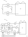
- Figure 1 shows one embodiment of the dehumidification arrangement 100.
- a greenhouse 102 whose interior air is being subject to dehumidification.
- Figure 1 shows that a portion of the interior air of the greenhouse is led to and circulated in a greenhouse air flow path 120 such that the air exhausted from the greenhouse in stage "A” passes via a first heat exchanger 104 to a second heat exchanger in stage "B", and then 106 back to the greenhouse in stage "C".
- Figure 1 shows also a second air flow path 122 that is an ambient air flow part, where ambient air, being air originating exterior of the greenhouse, is first input to the first heat exchanger 104 in stage "a", and the output air from the first heat exchanger 104 is then input to the second heat exchanger in stage "b", and after passing the second heat exchanger 106, returned to the outside air in stage "c".
- the greenhouse air flow path and ambient air flow path are arranged to respective piping having inlets and outlets leading to and out of the piping. The ambient air flow thus takes place wholly outside of the greenhouse in the embodiment of Figure 1 .
- the arrangement has at least three operation modes, which will be discussed in detail later in connection with Figure 2 .
- One of the operation modes is a dehumidification mode, and in the exemplary operation of the arrangement of Figure 1 , the first heat exchanger 104 carries out heat exchanging between the warm interior air of flow path 120, and the colder outside air of the air flow path 122, whereby heat is transferred from the interior air to the exterior air.
- the heat exchanging causes condensation when the warm and cold air come into contact with each other.
- the condensation may take place in a condensation wheel or a fixed type of heat exchanger, for instance.
- the greenhouse air 120 After the greenhouse air 120 has passed the first heat exchanger 104, it is led to the second heat exchanger 106 which is downstream of the first heat exchanger both in the greenhouse air flow path and the ambient air flow path.
- the first and second heat exchangers are thus fluidly connected by piping to each other both in the greenhouse and ambient air flow paths thus allowing the air to flow from the first heat exchanger to the second heat exchanger.
- the ambient air flow is arranged counter-currently to the greenhouse air flow both in the first heat exchanger and the second heat exchanger.
- the greenhouse air is to be heated by the ambient air from the air flow 122.
- the heat exchanging takes place by adsorption and thus the second heat exchanger may be a sorption heat exchanger, such as a sorption wheel rotary heat exchanger.
- the sorption heat exchanger contains sorption material which has strong affinity for water vapour.
- the material is typically a desiccant, which is capable of attracting and holding onto water molecules.
- the desiccant When the sorption heat exchanger is being used, and the desiccant has become loaded with water molecules, it will need to be regenerated by heating the desiccant material. This causes the water release from the material, which is then vented out from the sorption heat exchanger, which can be condensed back to water by cooling.
- the desiccant is then cooled for next cycle of water removal.
- a rotary wheel which has a matrix having a large surface area for interaction between the desiccant material and air passing through the heat exchanger.
- the rotor When the rotor has adsorbed water and is saturated, the rotor moves those sections to regeneration. In the regeneration, there is a separate process to separate the moisture from the desiccant, which can include passing warm or hot air through the rotor, which releases the moisture. Then the rotor may be cooled for the next cycle.
- the wheel rotates cyclically between the adsorption and regeneration zones.
- both heat exchangers 104 and 106 are for removing moisture from the greenhouse air flow path, the former by condensation and the latter by absorption. This provides the advantage of very efficient moisture removal in an energy efficient manner.
- the condensing heat exchanger works efficiently during winter time but during summer time a sorption heat exchanger has a better performance.
- the arrangement may be operated differently during winter time and summer time.
- the winter and summer are here defined by an average outside temperature, which can be + 5 Celsius, for instance. Temperatures above + 5 C may be considered as summer and below + 5 C are considered as winter.
- the parameters (temperature / relative humidity / water content) during winter time in various phases of the flow path 120 are (+18 Celcius (C) / 80 % RH / 10.3 g/kg) in phase A, (+2.6 C / 99 % RH / 4.5 g/kg) in phase B, and finally (9.9 C, 39 % RH and 3 g/kg) in stage C when heat exchanged with outside air of -3 C with relative humidity 85 %. It can thus be seen that the water content is effectively reduced in two stages, in both heat exchangers 104 and also 106. The initial water content 10.3 g/kg goes down to 4.5 g/kg in the heat exchanger 104 and then further down to 3 g/kg in the second heat exchanger 106.
- the parameters of the outside air in the stages a, b and c, respectively are (-3 C) / 85 % RH / 2.3 g/kg) in stage a, (+12.4 C) / 26.5 % RH / 2.3 g/kg) in stage b, and (+5.1 C) / 71.9 % RH / 3.9 g/kg) in stage c.
- the water content in the outside air has thus been increased in the process.
- Figure 2 shows another embodiment of the dehumidification arrangement 100 where the parts sharing the same numbers correspond to those in Figure 1 .
- the embodiment of Figure 2 has filters 110, 112 to filter the interior air flow A and exterior flow "a", respectively.
- the filters are provided to remove any impurities from the air flows.
- the arrangement may also include a fan 114 to increase the volume of the exterior air flow, and/or a fan 116 to affect the flow rate back to the greenhouse 102.
- the embodiment of Figure 2 also comprises a third heat exchanger 108 to increase the temperature of the air being returned to the greenhouse.
- the heat exchanger may receive heat from a further heat source, such as a renewal energy heat source or similar.
- the arrangement comprises a fourth heat exchanger 124 to recover heat from stream "c".
- There may be provided a heat pump 118 which is operationally connected to the third and fourth heat exchangers. The heat pump may extract heat of the flow in the fourth heat exchanger 124 and circulates a fluid between the heat exchangers 108 and 124 to heat up the stream C in the third heat exchanger 108 to a temperature level suitable for the greenhouse, e.g. to 20 C degrees.
- the heat pump 118 is applied for harvesting heat from both third 108 and fourth heat exchangers 124 and store the heat in a heat storage, such as a water tank, for later usage.
- a heat storage such as a water tank
- the arrangement may also comprise a first auxiliary flow path 130 branching from the ambient air flow path 122 upstream of the first heat exchanger 104 and ending downstream of the second 106 or third heat exchanger 108 in the greenhouse air flow path 120.
- a valve 132 for controlling the flow volume in the flow path 130.
- the purpose of the first flow path is to allow a second operation mode "cooling or heat harvest" where the primary intention is, instead of dehumidification, cooling of the air flow, and also securing that the ingoing air to the greenhouse is not too humid.
- the second heat exchanger 106 is stopped or at least substantially stopped, and the ambient air is directed directly to the flow path downstream of the third heat exchanger 108, such as to the outlet of fan 116.
- FIG. 2 shows also a humidifier 133 arranged downstream of the valve to the first auxiliary flow path 130, which humidifier may be used to add moisture to the flow 130 e.g. during very dry summer days.
- the humidifier may comprise mist spray nozzles, for instance, for adding humidity to the air flow.
- the arrangement may also comprise a second auxiliary flow path 134 starting upstream of the second heat exchanger 106 in the ambient flow path 122 and ending downstream of the second heat exchanger 106 in the ambient air flow path 122.
- the flow path 134 is thus arranged to circumvent the second heat exchanger 106.
- the advantage and purpose with the flow path 134 is to alleviate the risk of freezing of and/or defrosting the fourth heat exchanger 124 during very cold winter periods by leading warmer air than what would be normally received from the second heat exchanger 106 in the ambient air flow.
- the arrangement may also comprise a third auxiliary flow path 160 starting downstream of the fourth heat exchanger 124 and ending upstream of the first heat exchanger 104 in the ambient air flow path. There is arranged a third valve 162 for controlling the air flow in the third flow path.
- the purpose of the flow path is to enable use of cold outlet air from the fourth heat exchanger 124 to further improve the dehumidification performance of the first heat exchanger by lowering the temperature in the incoming ambient air flow "a".
- the third heat exchanger 108 can be applied in a cooling mode whereby it is also capable of removing moisture from the greenhouse air flow 120.
- the first, second and third heat exchangers may be capable of removing 6 kg/h, 87 kg/h and 15 kg/h, respectively.
- the first heat exchanger removes most of the water of the greenhouse air.
- the first heat exchanger would remove 174 kg/h, and the second heat exchanger 47 kg/h water out of the greenhouse air.
- HE refers to the respective four heat exchangers 104, 106, 108 and 124, P to the heat pump 118, F1 and F2 to respective fans 116 and 114 and V1 and V2 to respective valves 132 and 136.
- the first operation mode "Dehumidification”, the principal operation mode, refers to dehumidification of the greenhouse, that is, removal of water from the greenhouse air. This operational mode may be triggered by the greenhouse humidity exceeding a predetermined threshold value. In this operation mode, the first and second heat exchangers 104 and 106 are operational (ON) but the third and heat exchanger may take different roles depending on the ambient conditions.
- the third heat exchanger is applied for heating the return air to the greenhouse.
- the heat pump 118 is arranged to convey heat energy from the fourth heat exchanger 124 to the third heat exchanger 108. In this mode, the first auxiliary flow path 130 is not needed and the first valve 132 is closed.
- the temperature in the greenhouse may rise over a predetermined threshold value for the temperature, and cooling of the greenhouse air is needed.
- the pump is arranged to collect heat from both third and fourth heat exchangers 108, 124, and store the excess energy to a heat storage 452, such as a water tank shown in Figure 4 , for instance.
- the second auxiliary flow path 134 may be opened by the valve 136, whereby the warmer air effectively defrosts (Df in the table) the heat exchanger 124.
- the second heat exchanger In the second operation mode "Cooling / Heat harvest", the second heat exchanger is substantially non-operational meaning that it is either fully stopped or operates with very low intensity (e.g. less than 20%) of the nominal power.
- the third and fourth heat exchangers are operated in cooling mode where the pump harvest heat energy to a water storage.
- the first valve 132 is controlled (Cnt in the table) such that the first auxiliary flow path 130 may supply air directly to the input flow to the greenhouse.
- the goal is to keep air movement ongoing in the greenhouse, which is good for the crop development.
- This mode is applicable when the temperature and humidity are on appropriate level but air circulation is still beneficial.
- all the heat exchangers and pump are off and valves are closed (Cl in the table) and only the first fan 116 is in operation.
- Figure 3 shows another embodiment of the arrangement 300.
- the arrangement is very similar to the arrangement of Figure 2 , the only difference being that the greenhouse air flow and the respective equipment are arranged within the greenhouse.
- the ambient air flow path 122 is, to great extent, arranged within the greenhouse 300.
- only the inlet and outlet of the ambient air flow are being connected to the ambient air but all devices, such as filters, valves, heat exchangers and pumps and heat pumps are within the greenhouse.
- Figure 4 illustrates one embodiment of the heat pump structure the way of implementing the various operation modes, such as condensing and heat harvesting.
- the third and fourth heat exchangers 108 and 124 respectively as in the other figures.
- a usual heat pump loop for circulating a refrigerant comprising an evaporator 440, compressor 444 run by a motor M, a condenser 446 and an expander 442.
- the dashed lines in the evaporator 440 and the condenser illustrate heat exchange relations between the refrigerant and ambient fluid flows.
- a pump 448 which circulates a fluid in the fourth heat exchanger 124 for collecting heat energy thereof and consequently evaporating the refrigerant in the evaporator 440.
- the flow which may be water, is thus cooled in the evaporator before taking a new round in the fourth heat exchanger 124.
- a cold fluid flow which may also be water, may be directed for causing condensation when the cold fluid flow and by the compressor 444 heated gaseous refrigerant flow meet.
- the water flow receives thus energy in the condenser and is thereby heated.
- FIG. 4 shows also valves A, B, C and D, a flow pump 450 and heat storage 452, which may be a water tank, for instance.
- the valves C and D are closed and the three-way valves A and B are in such a position that they allow circulation to and from the third heat exchanger 108 but the connections to the external heat storage are closed.
- the heat pump thus circulates the fluid in the fourth heat exchanger 124 where the flow is heated, which energy is used in the evaporator 440 for heating the refrigerant.
- the heat pump gives energy to the fluid flow in the condenser 446, which heat energy is then provided to the third heat exchanger 108 to heat the greenhouse air flow.
- the heat pump is arranged to collect energy from both heat exchangers 108 and 124.
- the valves C and D are opened.
- valve D the cold fluid exiting the evaporator 440 is partly led also the third heat exchanger 108 in addition to be partly led to the fourth heat exchanger as in the other mode.
- valve C the flow heated in the third heat exchanger is utilized in the evaporator 440 in addition to the flow received from the fourth heat exchanger. So in practice, in this operation mode, the flows that circulate in the third and fourth heat exchangers are combined when entering and exiting the evaporator.
- the external flow to the condenser is coming from the external heating system, such as an external heat storage 452.
- the flow from the heat storage will be heated in the condenser by utilizing energy received from the third and fourth heat exchangers 108, 124.
- the arrangement may also comprise additional measurement devices and control logic for implementation of the embodiments.
- the measurement devices may comprise one or more temperature and/or humidity measurement devices in various places of the arrangement.
- the control logic which may be implemented by software, may receive input signals from the measurement devices and perform control actions based on the measurement results as disclosed in the connection of the drawings. Such control actions may include actions such as opening/closing valves, control of the fans and operation of the heat pump related actions.
- a method of dehumidification of greenhouse air wherein circulating greenhouse air in a greenhouse air flow.
- the greenhouse air flow there is provided a step of heat exchanging the greenhouse air against an ambient air flow in a first heat exchanger and also the step of heat exchanging the greenhouse air flow against an ambient air flow in a second heat exchanger wherein the greenhouse air flow and ambient air flow are received from the first heat exchanger.
Landscapes
- Chemical & Material Sciences (AREA)
- Engineering & Computer Science (AREA)
- Analytical Chemistry (AREA)
- Environmental Sciences (AREA)
- Life Sciences & Earth Sciences (AREA)
- Oil, Petroleum & Natural Gas (AREA)
- General Chemical & Material Sciences (AREA)
- General Engineering & Computer Science (AREA)
- Chemical Kinetics & Catalysis (AREA)
- Mechanical Engineering (AREA)
- Combustion & Propulsion (AREA)
- Thermal Sciences (AREA)
- Physics & Mathematics (AREA)
- Greenhouses (AREA)
Abstract
A control arrangement for controlling the temperature and/or humidity conditions of a greenhouse, wherein the arrangement comprises a greenhouse air flow for circulating greenhouse air, and an ambient air flow for circulating air originating exterior to the greenhouse, the arrangement comprising a first heat exchanger (104) for heat exchanging between the greenhouse air flow (A) and the ambient air flow (a), the first heat exchanger being configured to remove moisture from the greenhouse air flow by condensation, the arrangement further comprises a second heat exchanger (106) fluidly connected in series with the first heat exchanger (104) downstream of the first heat exchanger in the greenhouse air flow, the second heat exchanger (106) being further fluidly connected to the ambient air flow downstream of the first heat exchanger (104), wherein the second heat exchanger is provided for performing heat exchanging between the greenhouse air flow (B) and the ambient air flow (b), the second heat exchanger being configured to remove moisture from the greenhouse air flow by adsorption.
Description
- The invention relates to a method and an arrangement for control of humidity and/or temperature of a greenhouse.
- Removal of excess moisture from a greenhouse is important for prevention of damage such as growth of mold and fungus, prevention of diseases caused by spread of bacteria and viruses, and controlled evaporation of moisture from the leaf surfaces of the plants to optimize their growth.
- Document
WO 2017/062476 A1 describes a controlled and closed agricultural system having an enthalpy wheel and cooling coil. The cooling coil is positioned within a recirculating air duct, downstream of and in series with the enthalpy wheel. The cooling coil circulates a heat transfer fluid to remove additional heat from the recirculating air. - Document
US 2019/0364746 A1 discloses a dehumidification system includes a desiccant, a primary heat exchanger, a secondary heat exchanger, three fans, and a burner. The first fan generates a carbon dioxide airflow through the primary heat exchanger and the secondary heat exchanger. The burner generates a flame into one end of the primary heat exchanger. The second fan generates an airflow that flows over the secondary heat exchanger, the primary heat exchanger and through a first portion of the desiccant. The third fan generates an air flow that flows through a second portion of the desiccant. - The prior art fails to provide an efficient way of removing moisture from the greenhouse air, especially in cold environmental conditions. It is thus evident that there is a need for an efficient method and arrangement for humidity and/or temperature control of a greenhouse.
- It is the objective of the invention to provide an effective method and arrangement for control of humidity and/or temperature of a greenhouse. This is achieved with the invention that is the scope of the independent claims. Preferred embodiments have been disclosed in the dependent claims.
- The embodiments of the invention provide the significant advantage of efficient humidity and/or temperature control of a greenhouse.
- In the embodiments of the present invention, the condensation step is performed before the adsorption step. In this way, significant advantages can be obtained in terms of humidity reduction performance and energy savings when compared to systems where the adsorption phase is carried out before the condensation phase.
- The technical effect of the present invention, when first performing the condensation step, is that the outside air becomes far more suitable for the subsequent adsorption step. That is, in the initial condensation step, the outside air can be heated to a relatively high temperature and to a low humidity, which is optimal for the subsequent adsorption step thereby resulting into more efficient reduction of humidity while also saving significant amount of energy during the process. The advantages of the present invention are especially notable in low temperatures of the outside air, such as in the temperature range -10 C to +10 C but perform also better in other temperature ranges when compared to systems first performing an adsorption phase.
- The important specific of the present invention is thus the behaviour of the outside air in the process. While first performing the condensation phase, the relative humidity of the outside air passing the first heat exchanger can be pressed very low, which provides excellent basis for a subsequent adsorption step and thus for the efficiency of the overall process.
- The invention and its preferred embodiments are shown in the accompanying drawings, where
-
Figure 1 shows an embodiment of a humidity and/or temperature control arrangement of a greenhouse; -
Figure 2 shows a more detailed embodiment with respect toFigure 1 ; -
Figure 3 shows another embodiment of the arrangement; and -
Figure 4 shows an embodiment of a heat pump arrangement of the humidity and/or temperature control arrangement. - The embodiments relate to humidity and/or temperature control of a greenhouse. For optimal growth of the plants and prevention of other problems such as growth of mold or bacteria, dehumidification of the greenhouse is necessary.
-
Figure 1 shows one embodiment of thedehumidification arrangement 100. There is provided agreenhouse 102, whose interior air is being subject to dehumidification.Figure 1 shows that a portion of the interior air of the greenhouse is led to and circulated in a greenhouseair flow path 120 such that the air exhausted from the greenhouse in stage "A" passes via afirst heat exchanger 104 to a second heat exchanger in stage "B", and then 106 back to the greenhouse in stage "C".Figure 1 shows also a secondair flow path 122 that is an ambient air flow part, where ambient air, being air originating exterior of the greenhouse, is first input to thefirst heat exchanger 104 in stage "a", and the output air from thefirst heat exchanger 104 is then input to the second heat exchanger in stage "b", and after passing thesecond heat exchanger 106, returned to the outside air in stage "c". The greenhouse air flow path and ambient air flow path are arranged to respective piping having inlets and outlets leading to and out of the piping. The ambient air flow thus takes place wholly outside of the greenhouse in the embodiment ofFigure 1 . - The arrangement has at least three operation modes, which will be discussed in detail later in connection with
Figure 2 . One of the operation modes is a dehumidification mode, and in the exemplary operation of the arrangement ofFigure 1 , thefirst heat exchanger 104 carries out heat exchanging between the warm interior air offlow path 120, and the colder outside air of theair flow path 122, whereby heat is transferred from the interior air to the exterior air. The heat exchanging causes condensation when the warm and cold air come into contact with each other. The condensation may take place in a condensation wheel or a fixed type of heat exchanger, for instance. - After the
greenhouse air 120 has passed thefirst heat exchanger 104, it is led to thesecond heat exchanger 106 which is downstream of the first heat exchanger both in the greenhouse air flow path and the ambient air flow path. The first and second heat exchangers are thus fluidly connected by piping to each other both in the greenhouse and ambient air flow paths thus allowing the air to flow from the first heat exchanger to the second heat exchanger. The ambient air flow is arranged counter-currently to the greenhouse air flow both in the first heat exchanger and the second heat exchanger. - In the
second heat exchanger 106, the greenhouse air is to be heated by the ambient air from theair flow 122. In the second heat exchanger, the heat exchanging takes place by adsorption and thus the second heat exchanger may be a sorption heat exchanger, such as a sorption wheel rotary heat exchanger. Generally, the sorption heat exchanger contains sorption material which has strong affinity for water vapour. The material is typically a desiccant, which is capable of attracting and holding onto water molecules. When the sorption heat exchanger is being used, and the desiccant has become loaded with water molecules, it will need to be regenerated by heating the desiccant material. This causes the water release from the material, which is then vented out from the sorption heat exchanger, which can be condensed back to water by cooling. The desiccant is then cooled for next cycle of water removal. - Specifically, in a rotary wheel sorption heat exchanger, there is provided a rotary wheel which has a matrix having a large surface area for interaction between the desiccant material and air passing through the heat exchanger. When the rotor has adsorbed water and is saturated, the rotor moves those sections to regeneration. In the regeneration, there is a separate process to separate the moisture from the desiccant, which can include passing warm or hot air through the rotor, which releases the moisture. Then the rotor may be cooled for the next cycle. Thus, in a rotary wheel sorption heat exchanger, the wheel rotates cyclically between the adsorption and regeneration zones.
- Thus, in the embodiment of
Figure 1 , bothheat exchangers - Specifically, by providing two types of heat exchangers, condensing and adsorption heat exchangers affecting the greenhouse air flow, operational range of the arrangement can be optimized. In environments, where the ambient conditions have big temperature and/or moisture variations due to day/night or summer/winter, two different types of the heat exchangers ensure energy efficient operation in all conditions. For example, the condensing heat exchanger works efficiently during winter time but during summer time a sorption heat exchanger has a better performance.
- The arrangement may be operated differently during winter time and summer time. The winter and summer are here defined by an average outside temperature, which can be + 5 Celsius, for instance. Temperatures above + 5 C may be considered as summer and below + 5 C are considered as winter.
- As a non-limiting winter time use case example, the parameters (temperature / relative humidity / water content) during winter time in various phases of the
flow path 120 are (+18 Celcius (C) / 80 % RH / 10.3 g/kg) in phase A, (+2.6 C / 99 % RH / 4.5 g/kg) in phase B, and finally (9.9 C, 39 % RH and 3 g/kg) in stage C when heat exchanged with outside air of -3 C with relative humidity 85 %. It can thus be seen that the water content is effectively reduced in two stages, in bothheat exchangers 104 and also 106. The initial water content 10.3 g/kg goes down to 4.5 g/kg in theheat exchanger 104 and then further down to 3 g/kg in thesecond heat exchanger 106. - In the above example, the parameters of the outside air in the stages a, b and c, respectively, are (-3 C) / 85 % RH / 2.3 g/kg) in stage a, (+12.4 C) / 26.5 % RH / 2.3 g/kg) in stage b, and (+5.1 C) / 71.9 % RH / 3.9 g/kg) in stage c. The water content in the outside air has thus been increased in the process.
-
Figure 2 shows another embodiment of thedehumidification arrangement 100 where the parts sharing the same numbers correspond to those inFigure 1 . In addition toFigure 1 , the embodiment ofFigure 2 hasfilters fan 114 to increase the volume of the exterior air flow, and/or afan 116 to affect the flow rate back to thegreenhouse 102. - In addition to devices shown in
Figure 1 , the embodiment ofFigure 2 also comprises athird heat exchanger 108 to increase the temperature of the air being returned to the greenhouse. The heat exchanger may receive heat from a further heat source, such as a renewal energy heat source or similar. In another embodiment, the arrangement comprises afourth heat exchanger 124 to recover heat from stream "c". There may be provided aheat pump 118 which is operationally connected to the third and fourth heat exchangers. The heat pump may extract heat of the flow in thefourth heat exchanger 124 and circulates a fluid between theheat exchangers third heat exchanger 108 to a temperature level suitable for the greenhouse, e.g. to 20 C degrees. - In an embodiment, the
heat pump 118 is applied for harvesting heat from both third 108 andfourth heat exchangers 124 and store the heat in a heat storage, such as a water tank, for later usage. The arrangement of the heat pump is explained more in detail in connection withFigure 4 . - The arrangement may also comprise a first
auxiliary flow path 130 branching from the ambientair flow path 122 upstream of thefirst heat exchanger 104 and ending downstream of the second 106 orthird heat exchanger 108 in the greenhouseair flow path 120. There is provided avalve 132 for controlling the flow volume in theflow path 130. The purpose of the first flow path is to allow a second operation mode "cooling or heat harvest" where the primary intention is, instead of dehumidification, cooling of the air flow, and also securing that the ingoing air to the greenhouse is not too humid. In this second operation mode, thesecond heat exchanger 106 is stopped or at least substantially stopped, and the ambient air is directed directly to the flow path downstream of thethird heat exchanger 108, such as to the outlet offan 116. In this operation mode the third andfourth heat exchangers heat pump 118 such that they are arranged to cool the air flows passing through them.Figure 2 shows also ahumidifier 133 arranged downstream of the valve to the firstauxiliary flow path 130, which humidifier may be used to add moisture to theflow 130 e.g. during very dry summer days. The humidifier may comprise mist spray nozzles, for instance, for adding humidity to the air flow. - The arrangement may also comprise a second
auxiliary flow path 134 starting upstream of thesecond heat exchanger 106 in theambient flow path 122 and ending downstream of thesecond heat exchanger 106 in the ambientair flow path 122. Theflow path 134 is thus arranged to circumvent thesecond heat exchanger 106. There is provided avalve 136 for controlling the flow volume in theflow path 134. The advantage and purpose with theflow path 134 is to alleviate the risk of freezing of and/or defrosting thefourth heat exchanger 124 during very cold winter periods by leading warmer air than what would be normally received from thesecond heat exchanger 106 in the ambient air flow. - The arrangement may also comprise a third
auxiliary flow path 160 starting downstream of thefourth heat exchanger 124 and ending upstream of thefirst heat exchanger 104 in the ambient air flow path. There is arranged athird valve 162 for controlling the air flow in the third flow path. The purpose of the flow path is to enable use of cold outlet air from thefourth heat exchanger 124 to further improve the dehumidification performance of the first heat exchanger by lowering the temperature in the incoming ambient air flow "a". - In some embodiments, e.g. in summer time, the
third heat exchanger 108 can be applied in a cooling mode whereby it is also capable of removing moisture from thegreenhouse air flow 120. In an exemplary case with 30 000 kg/h air flow, the first, second and third heat exchangers may be capable of removing 6 kg/h, 87 kg/h and 15 kg/h, respectively. - In a winter operation mode, when the ambient air is colder than in the summer, the first heat exchanger removes most of the water of the greenhouse air. In the same exemplary case as above with 30 000 kg/h greenhouse air circulation, and -3 C ambient air temperature, the first heat exchanger would remove 174 kg/h, and the second heat exchanger 47 kg/h water out of the greenhouse air.
- There are three operational modes in the arrangement, which are further explained with reference to the following table, where it is explained how different devices are being operated in the various operation modes. In the below table, HE refers to the respective four
heat exchangers heat pump 118, F1 and F2 torespective fans respective valves Mode HE1 HE2 HE3 HE4 P F1 F2 V1 V2 Dehumidif. On On Heat (W) Cool (S) Cool HE4->HE3 (W) HE4+HE3 (S) On On Cl Df Cool/ Heat harvest On Off / slow Cool Cool HE4+HE3 (S) to water storage On On Cnt Cl Ventilation Off Off Off Off Off On Off Cl Cl - The first operation mode "Dehumidification", the principal operation mode, refers to dehumidification of the greenhouse, that is, removal of water from the greenhouse air. This operational mode may be triggered by the greenhouse humidity exceeding a predetermined threshold value. In this operation mode, the first and
second heat exchangers - During winter time (W in the table) or when the greenhouse temperature drops too low, the third heat exchanger is applied for heating the return air to the greenhouse. In one embodiment, the
heat pump 118 is arranged to convey heat energy from thefourth heat exchanger 124 to thethird heat exchanger 108. In this mode, the firstauxiliary flow path 130 is not needed and thefirst valve 132 is closed. - During summer time (S in the table), the temperature in the greenhouse may rise over a predetermined threshold value for the temperature, and cooling of the greenhouse air is needed. Then, the pump is arranged to collect heat from both third and
fourth heat exchangers heat storage 452, such as a water tank shown inFigure 4 , for instance. - In one use case of the dehumidification mode, during winter time if the
fourth heat exchanger 124 is in risk of freezing, the secondauxiliary flow path 134 may be opened by thevalve 136, whereby the warmer air effectively defrosts (Df in the table) theheat exchanger 124. - In the second operation mode "Cooling / Heat harvest", the second heat exchanger is substantially non-operational meaning that it is either fully stopped or operates with very low intensity (e.g. less than 20%) of the nominal power. The third and fourth heat exchangers are operated in cooling mode where the pump harvest heat energy to a water storage. The
first valve 132 is controlled (Cnt in the table) such that the firstauxiliary flow path 130 may supply air directly to the input flow to the greenhouse. - In the third operation mode "Ventilation", the goal is to keep air movement ongoing in the greenhouse, which is good for the crop development. This mode is applicable when the temperature and humidity are on appropriate level but air circulation is still beneficial. In this mode all the heat exchangers and pump are off and valves are closed (Cl in the table) and only the
first fan 116 is in operation. -
Figure 3 shows another embodiment of thearrangement 300. The arrangement is very similar to the arrangement ofFigure 2 , the only difference being that the greenhouse air flow and the respective equipment are arranged within the greenhouse. Also the ambientair flow path 122 is, to great extent, arranged within thegreenhouse 300. In the embodiment shown, only the inlet and outlet of the ambient air flow are being connected to the ambient air but all devices, such as filters, valves, heat exchangers and pumps and heat pumps are within the greenhouse. Some hybrid solutions between the extremes ofFigures 1 and3 are possible where some equipment is within and some outside the greenhouse. -
Figure 4 illustrates one embodiment of the heat pump structure the way of implementing the various operation modes, such as condensing and heat harvesting. - There are shown the third and
fourth heat exchangers evaporator 440,compressor 444 run by a motor M, acondenser 446 and anexpander 442. The dashed lines in theevaporator 440 and the condenser illustrate heat exchange relations between the refrigerant and ambient fluid flows. There is provided apump 448, which circulates a fluid in thefourth heat exchanger 124 for collecting heat energy thereof and consequently evaporating the refrigerant in theevaporator 440. The flow, which may be water, is thus cooled in the evaporator before taking a new round in thefourth heat exchanger 124. - To the
condenser 446, a cold fluid flow, which may also be water, may be directed for causing condensation when the cold fluid flow and by thecompressor 444 heated gaseous refrigerant flow meet. The water flow receives thus energy in the condenser and is thereby heated. -
Figure 4 shows also valves A, B, C and D, aflow pump 450 andheat storage 452, which may be a water tank, for instance. - In the dehumidification operation mode where the greenhouse air flow has been condensed and thus cooled in two
heat exchangers third heat exchanger 108 but the connections to the external heat storage are closed. For collecting energy, the heat pump thus circulates the fluid in thefourth heat exchanger 124 where the flow is heated, which energy is used in theevaporator 440 for heating the refrigerant. For releasing energy, the heat pump gives energy to the fluid flow in thecondenser 446, which heat energy is then provided to thethird heat exchanger 108 to heat the greenhouse air flow. - In the cooling and heat harvesting mode, the heat pump is arranged to collect energy from both
heat exchangers evaporator 440 is partly led also thethird heat exchanger 108 in addition to be partly led to the fourth heat exchanger as in the other mode. By opening valve C, the flow heated in the third heat exchanger is utilized in theevaporator 440 in addition to the flow received from the fourth heat exchanger. So in practice, in this operation mode, the flows that circulate in the third and fourth heat exchangers are combined when entering and exiting the evaporator. - Furthermore, in this operation mode, the external flow to the condenser is coming from the external heating system, such as an
external heat storage 452. Thus, the flow from the heat storage will be heated in the condenser by utilizing energy received from the third andfourth heat exchangers - The arrangement may also comprise additional measurement devices and control logic for implementation of the embodiments. The measurement devices may comprise one or more temperature and/or humidity measurement devices in various places of the arrangement. The control logic, which may be implemented by software, may receive input signals from the measurement devices and perform control actions based on the measurement results as disclosed in the connection of the drawings. Such control actions may include actions such as opening/closing valves, control of the fans and operation of the heat pump related actions.
- In an aspect, there is provided a method of dehumidification of greenhouse air wherein circulating greenhouse air in a greenhouse air flow. In the greenhouse air flow, there is provided a step of heat exchanging the greenhouse air against an ambient air flow in a first heat exchanger and also the step of heat exchanging the greenhouse air flow against an ambient air flow in a second heat exchanger wherein the greenhouse air flow and ambient air flow are received from the first heat exchanger.
- It is clear that when the technology develops the inventive idea can be implemented in various ways. The invention and its embodiments are thus not limited to disclosed embodiments but can vary within the appended claims.
Claims (15)
- A control arrangement for controlling the temperature and/or humidity conditions of a greenhouse, characterized in that the arrangement comprises a greenhouse air flow (120) for circulating greenhouse air, and an ambient air flow (122) for circulating air originating exterior to the greenhouse, the arrangement comprising a first heat exchanger (104) for heat exchanging between the greenhouse air flow and the ambient air flow, the first heat exchanger being configured to remove moisture from the greenhouse air flow (120) by condensation, the arrangement further comprises a second heat exchanger (106) fluidly connected in series with the first heat exchanger (104) downstream of the first heat exchanger in the greenhouse air flow, the second heat exchanger (106) being further fluidly connected to the ambient air flow (122) downstream of the first heat exchanger (104), wherein the second heat exchanger is provided for performing heat exchanging between the greenhouse air flow and the ambient air flow, the second heat exchanger being configured to remove moisture from the greenhouse air flow by adsorption.
- A control arrangement for controlling the temperature and/or humidity conditions of a greenhouse according to any preceding claim, characterized in that the arrangement comprises a third heat exchanger (108) downstream of the second heat exchanger (106), the third heat exchanger being configured to heat the greenhouse air before the air exiting the greenhouse air flow and being returned to the greenhouse interior air.
- A control arrangement for controlling the temperature and/or humidity conditions of a greenhouse according to any preceding claim, characterized in that the arrangement comprises a fourth heat exchanger (124) for extracting heat energy from the ambient air flow downstream of the second heat exchanger (106).
- A control arrangement for controlling the temperature and/or humidity conditions of a greenhouse according to any preceding claim, characterized in that the arrangement comprises a heat pump (118) operationally connected to the third (108) and fourth (124) heat exchangers.
- A control arrangement for controlling the temperature and/or humidity conditions of a greenhouse according to any preceding claim, characterized in that the arrangement comprises a first auxiliary flow path (130) whose start point is arranged upstream of the first heat exchanger (104) in the ambient air flow path (122), and end point of the first auxiliary flow path is arranged downstream of the third heat exchanger in the greenhouse air flow path, and the arrangement comprises a valve (132) for controlling the flow volume in the first auxiliary flow path.
- A control arrangement for controlling the temperature and/or humidity conditions of a greenhouse according to any preceding claim, characterized in that the arrangement comprises a second auxiliary flow path (134) whose start point is arranged upstream of the second heat exchanger (104) in the ambient air flow path (122), and end point is arranged downstream of the second heat exchanger in the ambient air flow path, and the arrangement comprises a valve (136) for controlling the flow volume in the second auxiliary flow path (134).
- A control arrangement for controlling the temperature and/or humidity conditions of a greenhouse according to any preceding claim, characterized in that the arrangement comprising a dehumidification operation mode, in which dehumidification operation mode the first and second heat exchangers are operational in performing the respective heat exchanging and thus removing moisture from the greenhouse air.
- A control arrangement for controlling the temperature and/or humidity conditions of a greenhouse according to any preceding claim, characterized in that in the dehumidification operation mode, when the ambient temperature is below a predetermined temperature threshold thus being representative of a winter time, the heat pump (118) is configured to convey heat energy from the fourth heat exchanger (124) to the third heat exchanger (108) for warming the greenhouse air flow before returning to the greenhouse.
- A control arrangement for controlling the temperature and/or humidity conditions of a greenhouse according to claim 8, characterized in that in the dehumidification operation mode, when the ambient temperature is below a predetermined temperature threshold thus being representative of a winter time, the arrangement is configured to cyclically control the second valve (136) to open to allow air flow in the second auxiliary flow path in order to defrost the fourth heat exchanger (124).
- A control arrangement for controlling the temperature and/or humidity conditions of a greenhouse according to any preceding claim, characterized in that in the dehumidification operation mode, when the ambient temperature is over a predetermined temperature threshold thus being representative of a summer time, the heat pump (118) is configured to harvest heat energy from the third heat exchanger (108) and the fourth heat exchanger (124) thereby cooling the greenhouse air flow path, and the heat pump is configured to store the excess energy to an energy storage (452).
- A control arrangement for controlling the temperature and/or humidity conditions of a greenhouse according to any preceding claim, characterized in that the arrangement comprises a cooling and heat harvesting operation mode, the second heat exchanger (106) is either stopped or operated at less than 20 % power from the nominal power, and the heat pump (118) is configured to harvest heat energy from the third heat exchanger (108) and the fourth heat exchanger (124) thereby cooling the greenhouse air flow path, and the heat pump is configured to store the excess energy to an energy storage (452).
- A control arrangement for controlling the temperature and/or humidity conditions of a greenhouse according to claim 11, characterized in that the arrangement is configured to control the first valve (132) to control and allow air flow via the first auxiliary flow path (130).
- A control arrangement for controlling the temperature and/or humidity conditions of a greenhouse according to any preceding claim, characterized in that the arrangement comprises a ventilation operation mode, wherein the only operational device is a fan (116) arranged downstream of the third heat exchanger in the greenhouse air flow path.
- A control arrangement for controlling the temperature and/or humidity conditions of a greenhouse to any preceding claim, characterized in that the arrangement comprises a third auxiliary flow path (160) whose start point is arranged downstream of the fourth heat exchanger (124) in the ambient air flow path (122), and end point is arranged upstream of the first heat exchanger in the ambient airflow path, and the arrangement comprises a valve (136) for controlling the flow volume in the third auxiliary flow path (160).
- A method of dehumidification of greenhouse air wherein circulating greenhouse air in a greenhouse air flow path, characterized in that in the greenhouse air flow path (120):heat exchanging, the greenhouse air against an ambient air flow (122) in a first heat exchanger (104) wherein the first heat exchanger removes moisture from the greenhouse air flow by condensing;heat exchanging the greenhouse air flow (120) against an ambient air flow (122) in a second heat exchanger (106) wherein the greenhouse air flow and ambient air flow are received from the first heat exchanger wherein the second heat exchanger removes moisture from the greenhouse air flow by adsorption; andreturning the greenhouse air flow to the greenhouse.
Applications Claiming Priority (1)
| Application Number | Priority Date | Filing Date | Title |
|---|---|---|---|
| FI20237147A FI131691B1 (en) | 2023-08-29 | 2023-08-29 | GREENHOUSE AIR HUMIDITY AND/OR TEMPERATURE CONTROL |
Publications (1)
| Publication Number | Publication Date |
|---|---|
| EP4516088A1 true EP4516088A1 (en) | 2025-03-05 |
Family
ID=91738769
Family Applications (1)
| Application Number | Title | Priority Date | Filing Date |
|---|---|---|---|
| EP24185125.2A Pending EP4516088A1 (en) | 2023-08-29 | 2024-06-27 | Greenhouse air humidity and/or temperature control |
Country Status (4)
| Country | Link |
|---|---|
| US (1) | US12589353B2 (en) |
| EP (1) | EP4516088A1 (en) |
| CA (1) | CA3251141A1 (en) |
| FI (1) | FI131691B1 (en) |
Citations (4)
| Publication number | Priority date | Publication date | Assignee | Title |
|---|---|---|---|---|
| JP4423499B2 (en) * | 2004-02-17 | 2010-03-03 | 宮崎県 | Absorption type dehumidification air conditioning system |
| WO2017062476A1 (en) | 2015-10-08 | 2017-04-13 | Harvest Air, LLC | Contained growing space and environmental control system |
| US20180177140A1 (en) * | 2016-12-22 | 2018-06-28 | James GALLANT | Controlled environment greenhouse |
| US20190364746A1 (en) | 2018-05-30 | 2019-12-05 | Therma-Stor LLC | Greenhouse Desiccant Dehumidifier and Carbon Dioxide Generator |
Family Cites Families (29)
| Publication number | Priority date | Publication date | Assignee | Title |
|---|---|---|---|---|
| US4093435A (en) * | 1973-11-23 | 1978-06-06 | Wing Industries Inc. | Total heat energy exchangers |
| JPS5470940A (en) * | 1977-11-10 | 1979-06-07 | Yoshitane Kurimoto | Greenhouse apparatus |
| US4567939A (en) * | 1984-02-02 | 1986-02-04 | Dumbeck Robert F | Computer controlled air conditioning systems |
| US5579647A (en) * | 1993-01-08 | 1996-12-03 | Engelhard/Icc | Desiccant assisted dehumidification and cooling system |
| US5650221A (en) * | 1995-07-06 | 1997-07-22 | Laroche Industries, Inc. | High strength, low pressure drop sensible and latent heat exchange wheel |
| US6446385B1 (en) * | 2001-06-12 | 2002-09-10 | William C. Crutcher | Greenhouse system with co-generation power supply, heating and exhaust gas fertilization |
| US6751964B2 (en) * | 2002-06-28 | 2004-06-22 | John C. Fischer | Desiccant-based dehumidification system and method |
| US7228657B2 (en) * | 2003-07-10 | 2007-06-12 | Controlled Environments Limited | Climate control for a greenhouse |
| WO2005041633A2 (en) * | 2003-10-31 | 2005-05-12 | Cornell Research Foundation, Inc. | Systems and methods for providing optimal light-co2 combinations for plant production |
| US9730397B2 (en) * | 2006-06-29 | 2017-08-15 | Houweling Nurseries Oxnard, Inc. | Greenhouse and forced greenhouse climate control system and method |
| NL1032450C2 (en) * | 2006-09-06 | 2008-03-07 | Uptime Technology B V | Device and method for cooling a space in a data center with the aid of recirculation air. |
| KR100795101B1 (en) * | 2006-10-09 | 2008-01-17 | 한국과학기술연구원 | Dehumidifier and air conditioning system and system having same |
| US7886986B2 (en) * | 2006-11-08 | 2011-02-15 | Semco Inc. | Building, ventilation system, and recovery device control |
| WO2008082405A1 (en) * | 2006-12-29 | 2008-07-10 | Carrier Corporation | System and method for controlling temperature and humidity of a controlled space |
| JP4720772B2 (en) * | 2007-04-06 | 2011-07-13 | トヨタ自動車株式会社 | Dehumidifying / humidifying device for vehicles |
| US20100242507A1 (en) * | 2009-03-24 | 2010-09-30 | Milton Meckler | Dynamic outside air management system and method |
| US20110041395A1 (en) * | 2009-08-20 | 2011-02-24 | BioSynEnergy LLC | Integrated Agriculture and Aquaculture Production System |
| NL2003671C2 (en) * | 2009-10-19 | 2011-04-20 | Level Holding Bv | CLIMATE MANAGEMENT DEVICE FOR CASES. |
| US8790451B1 (en) * | 2010-09-17 | 2014-07-29 | Pvt Solar, Inc. | Method and system for integrated home cooling utilizing solar power |
| EP3339756B1 (en) * | 2010-12-22 | 2019-11-06 | Mitsubishi Electric Corporation | Air-conditioning system and humidity control device |
| US9513065B2 (en) * | 2011-11-01 | 2016-12-06 | Ruskin Company | Energy recovery ventilation control system |
| US9976822B2 (en) * | 2012-03-22 | 2018-05-22 | Nortek Air Solutions Canada, Inc. | System and method for conditioning air in an enclosed structure |
| US20140235157A1 (en) * | 2013-02-15 | 2014-08-21 | Venmar Ces, Inc. | Dedicated outdoor air system with pre-heating and method for same |
| US9109808B2 (en) * | 2013-03-13 | 2015-08-18 | Venmar Ces, Inc. | Variable desiccant control energy exchange system and method |
| WO2015054303A1 (en) * | 2013-10-08 | 2015-04-16 | Johnson Controls Technology Company | Systems and methods for air conditioning a building using an energy recovery wheel |
| US9161498B1 (en) * | 2014-04-04 | 2015-10-20 | Greenhouse Hvac Llc | Climate control system and method for a greenhouse |
| US9216405B1 (en) * | 2014-06-26 | 2015-12-22 | Kraton Polymers U.S. Llc | Rotary enthalpy exchange wheel having sulfonated block copolymer |
| WO2020060402A1 (en) * | 2018-09-20 | 2020-03-26 | B. Van Den Berg Holding B.V. | A greenhouse having a climate control system, climate control system and method of operating the greenhouse |
| CN113175704B (en) * | 2021-04-13 | 2022-06-28 | 上海交通大学 | Greenhouse heat and humidity regulation and control and energy-saving and water-saving device and method |
-
2023
- 2023-08-29 FI FI20237147A patent/FI131691B1/en active
-
2024
- 2024-06-27 EP EP24185125.2A patent/EP4516088A1/en active Pending
- 2024-07-30 CA CA3251141A patent/CA3251141A1/en active Pending
- 2024-08-08 US US18/798,651 patent/US12589353B2/en active Active
Patent Citations (4)
| Publication number | Priority date | Publication date | Assignee | Title |
|---|---|---|---|---|
| JP4423499B2 (en) * | 2004-02-17 | 2010-03-03 | 宮崎県 | Absorption type dehumidification air conditioning system |
| WO2017062476A1 (en) | 2015-10-08 | 2017-04-13 | Harvest Air, LLC | Contained growing space and environmental control system |
| US20180177140A1 (en) * | 2016-12-22 | 2018-06-28 | James GALLANT | Controlled environment greenhouse |
| US20190364746A1 (en) | 2018-05-30 | 2019-12-05 | Therma-Stor LLC | Greenhouse Desiccant Dehumidifier and Carbon Dioxide Generator |
Also Published As
| Publication number | Publication date |
|---|---|
| FI131691B1 (en) | 2025-09-23 |
| US12589353B2 (en) | 2026-03-31 |
| CA3251141A1 (en) | 2025-06-05 |
| FI20237147A1 (en) | 2025-03-01 |
| US20250073637A1 (en) | 2025-03-06 |
Similar Documents
| Publication | Publication Date | Title |
|---|---|---|
| KR101542334B1 (en) | Dehumidification system | |
| CN204665595U (en) | Tandem heat-recycling air treatment device | |
| CN204665596U (en) | Direct-expansion type heat-recycling air treatment device | |
| JP4582243B2 (en) | Dehumidification system | |
| CN107677010B (en) | Air conditioning system without dew point control and control method | |
| KR20110000211A (en) | Dry Room Desiccant Dehumidification System Using Array and Control Method | |
| CN110173776B (en) | A kind of fresh air treatment device with pre-cooling rotor for humidity control | |
| CN103292392A (en) | Multistage rotary-wheel dehumidification device with auxiliary heat rejection and application method thereof | |
| CN113446764A (en) | Independent temperature and humidity control system for plant cabin in severe cold region | |
| JP2006308241A (en) | Heat pump type air conditioner | |
| CN115930314A (en) | Combined cascade heat pump synergistic type rotary dehumidifier with step condensation regeneration | |
| CN110763005B (en) | Heat pump type double-fluid dehumidification heating dryer and drying chamber | |
| KR100643079B1 (en) | Energy-saving air conditioner using heat pump | |
| CN107270456B (en) | An energy-saving integrated cooling, heating, and dehumidification device | |
| CN106369722B (en) | A dual-mode solution humidity control fresh air air conditioning unit and air humidity control method | |
| US20210148587A1 (en) | Dehumidifiier cascade system and process | |
| CN223005070U (en) | Dehumidification system | |
| US12589353B2 (en) | Greenhouse air humidity and/or temperature control | |
| CN221944362U (en) | An integrated fresh air type low temperature regeneration rotary dehumidifier unit | |
| CN101457956A (en) | Fresh air processing method for air conditioning plant and system thereof | |
| ES2230422T3 (en) | PROCEDURE AND SYSTEM FOR INTERNAL AIR TREATMENT. | |
| CN217653993U (en) | Wet film air conditioning equipment | |
| CN216769635U (en) | Fresh air conditioning unit | |
| JP3743581B2 (en) | Heat pump and operation method thereof | |
| JP2014126255A (en) | Humidity controller and dehumidification system using humidity controller |
Legal Events
| Date | Code | Title | Description |
|---|---|---|---|
| PUAI | Public reference made under article 153(3) epc to a published international application that has entered the european phase |
Free format text: ORIGINAL CODE: 0009012 |
|
| STAA | Information on the status of an ep patent application or granted ep patent |
Free format text: STATUS: THE APPLICATION HAS BEEN PUBLISHED |
|
| AK | Designated contracting states |
Kind code of ref document: A1 Designated state(s): AL AT BE BG CH CY CZ DE DK EE ES FI FR GB GR HR HU IE IS IT LI LT LU LV MC ME MK MT NL NO PL PT RO RS SE SI SK SM TR |
|
| STAA | Information on the status of an ep patent application or granted ep patent |
Free format text: STATUS: REQUEST FOR EXAMINATION WAS MADE |
|
| 17P | Request for examination filed |
Effective date: 20250822 |