EP4513896A2 - Lautsprecher - Google Patents
Lautsprecher Download PDFInfo
- Publication number
- EP4513896A2 EP4513896A2 EP25151587.0A EP25151587A EP4513896A2 EP 4513896 A2 EP4513896 A2 EP 4513896A2 EP 25151587 A EP25151587 A EP 25151587A EP 4513896 A2 EP4513896 A2 EP 4513896A2
- Authority
- EP
- European Patent Office
- Prior art keywords
- diaphragm
- surround
- loudspeaker assembly
- cone
- range
- Prior art date
- Legal status (The legal status is an assumption and is not a legal conclusion. Google has not performed a legal analysis and makes no representation as to the accuracy of the status listed.)
- Pending
Links
Images





Classifications
-
- H—ELECTRICITY
- H04—ELECTRIC COMMUNICATION TECHNIQUE
- H04R—LOUDSPEAKERS, MICROPHONES, GRAMOPHONE PICK-UPS OR LIKE ACOUSTIC ELECTROMECHANICAL TRANSDUCERS; ELECTRIC HEARING AIDS; PUBLIC ADDRESS SYSTEMS
- H04R7/00—Diaphragms for electromechanical transducers; Cones
- H04R7/02—Diaphragms for electromechanical transducers; Cones characterised by the construction
- H04R7/12—Non-planar diaphragms or cones
-
- H—ELECTRICITY
- H04—ELECTRIC COMMUNICATION TECHNIQUE
- H04R—LOUDSPEAKERS, MICROPHONES, GRAMOPHONE PICK-UPS OR LIKE ACOUSTIC ELECTROMECHANICAL TRANSDUCERS; ELECTRIC HEARING AIDS; PUBLIC ADDRESS SYSTEMS
- H04R7/00—Diaphragms for electromechanical transducers; Cones
- H04R7/16—Mounting or tensioning of diaphragms or cones
- H04R7/18—Mounting or tensioning of diaphragms or cones at the periphery
-
- H—ELECTRICITY
- H04—ELECTRIC COMMUNICATION TECHNIQUE
- H04R—LOUDSPEAKERS, MICROPHONES, GRAMOPHONE PICK-UPS OR LIKE ACOUSTIC ELECTROMECHANICAL TRANSDUCERS; ELECTRIC HEARING AIDS; PUBLIC ADDRESS SYSTEMS
- H04R2307/00—Details of diaphragms or cones for electromechanical transducers, their suspension or their manufacture covered by H04R7/00 or H04R31/003, not provided for in any of its subgroups
- H04R2307/025—Diaphragms comprising polymeric materials
-
- H—ELECTRICITY
- H04—ELECTRIC COMMUNICATION TECHNIQUE
- H04R—LOUDSPEAKERS, MICROPHONES, GRAMOPHONE PICK-UPS OR LIKE ACOUSTIC ELECTROMECHANICAL TRANSDUCERS; ELECTRIC HEARING AIDS; PUBLIC ADDRESS SYSTEMS
- H04R2307/00—Details of diaphragms or cones for electromechanical transducers, their suspension or their manufacture covered by H04R7/00 or H04R31/003, not provided for in any of its subgroups
- H04R2307/029—Diaphragms comprising fibres
-
- H—ELECTRICITY
- H04—ELECTRIC COMMUNICATION TECHNIQUE
- H04R—LOUDSPEAKERS, MICROPHONES, GRAMOPHONE PICK-UPS OR LIKE ACOUSTIC ELECTROMECHANICAL TRANSDUCERS; ELECTRIC HEARING AIDS; PUBLIC ADDRESS SYSTEMS
- H04R2307/00—Details of diaphragms or cones for electromechanical transducers, their suspension or their manufacture covered by H04R7/00 or H04R31/003, not provided for in any of its subgroups
- H04R2307/204—Material aspects of the outer suspension of loudspeaker diaphragms
-
- H—ELECTRICITY
- H04—ELECTRIC COMMUNICATION TECHNIQUE
- H04R—LOUDSPEAKERS, MICROPHONES, GRAMOPHONE PICK-UPS OR LIKE ACOUSTIC ELECTROMECHANICAL TRANSDUCERS; ELECTRIC HEARING AIDS; PUBLIC ADDRESS SYSTEMS
- H04R2307/00—Details of diaphragms or cones for electromechanical transducers, their suspension or their manufacture covered by H04R7/00 or H04R31/003, not provided for in any of its subgroups
- H04R2307/207—Shape aspects of the outer suspension of loudspeaker diaphragms
-
- H—ELECTRICITY
- H04—ELECTRIC COMMUNICATION TECHNIQUE
- H04R—LOUDSPEAKERS, MICROPHONES, GRAMOPHONE PICK-UPS OR LIKE ACOUSTIC ELECTROMECHANICAL TRANSDUCERS; ELECTRIC HEARING AIDS; PUBLIC ADDRESS SYSTEMS
- H04R2499/00—Aspects covered by H04R or H04S not otherwise provided for in their subgroups
- H04R2499/10—General applications
- H04R2499/13—Acoustic transducers and sound field adaptation in vehicles
-
- H—ELECTRICITY
- H04—ELECTRIC COMMUNICATION TECHNIQUE
- H04R—LOUDSPEAKERS, MICROPHONES, GRAMOPHONE PICK-UPS OR LIKE ACOUSTIC ELECTROMECHANICAL TRANSDUCERS; ELECTRIC HEARING AIDS; PUBLIC ADDRESS SYSTEMS
- H04R31/00—Apparatus or processes specially adapted for the manufacture of transducers or diaphragms therefor
- H04R31/003—Apparatus or processes specially adapted for the manufacture of transducers or diaphragms therefor for diaphragms or their outer suspension
Definitions
- the present invention is generally related to the field of external sound generating devices for a vehicle.
- it is related to an acoustic vehicle warning system for outputting an acoustic warning signal.
- An Acoustic Vehicle Alerting System is designed to emit vehicle warning sounds and alert pedestrians to the presence of electric drive vehicles.
- HEVs hybrid
- PHEVs plug-in hybrid
- BEVs full battery electric vehicles
- a horn intended for producing a warning signal is installed in every vehicle.
- Horn signals have a typical sound that is automatically recognized by people as a horn.
- Worldwide people have grown accustomed to how vehicle horns sound, in spite of tonal differences that may be observed between horn sound signals.
- US8217767 B2 discloses a vehicular horn device that can be used as a dynamic speaker so as to generate a false engine sound.
- the shortage of a low-pitched sound in a parametric speaker device is complemented with a false engine sound which the vehicular horn device generates.
- a sound tone of the false engine sound which the pedestrian hears changes, enabling the pedestrian to easily notice the approach or presence of the vehicle.
- US10406976 B2 relates to a vehicle comprising a multi-purpose automotive sound device for alerting pedestrians.
- the sound device operates as a horn in a first mode in response to an external input (e.g. from the driver) and as a speaker or other sound generating device in a second mode in response to the vehicle moving in reverse or moving forwards at a speed satisfying a given threshold.
- FR2983025 presents a system to generate external sound for use in electric motor vehicles.
- a hybrid transducer controlled by a common interface that assures distribution of power between a piezo-electric transducer and a magnetic transducer according to a required function, e.g. alarm function and sound warning function.
- a diaphragm in the form of a cone, made from a rigid material, connected to a surround, made from a compliant/flexible material, that allows for the cone to easily move axially.
- the cone is provided with a central hole for connection to the voice coil former (it is thus an open cone). This hole is closed by gluing a rigid dust cap above the voice coil former onto the cone.
- the effective acoustic radiating equivalent piston surface area of a membrane is small as the displacement decreases radially from maximum in the center, prescribed by the voice coil, down to zero at the clamped edge (see Figure 1(b) )
- the modal behavior of the clamped membrane is not ideal either as a multitude of resonances occur already at low and medium frequencies in the rated frequency range of the loudspeaker.
- state of the art cone loudspeakers may use a cone material with a Young's modulus in the range of 2 to 10 GPa.
- the connection between the cone and the frame is carried out by means of a compliant member, the surround.
- Surrounds are typically made from rubber, with a Young's modulus in the range of 2 to 10 MPa.
- the surround is approximately 1000 times more compliant than the cone. This allows for large excursions or movements of the stiff cone.
- the cone may move from its relaxed position 2 to 10 mm (that is, its position is the relaxed position ⁇ 2 to ⁇ 10 mm); in some cases it may be up to ⁇ 20 mm for automotive loudspeakers for effective radiation of low frequencies.
- This glue area typically expands over a radial distance of 3 to 4mm for a strong and durable connection.
- the specific mass of the membrane is often more than doubled, as the specific mass of the cone, the specific mass of the surround and the glue amount add up.
- this additional annular mass loading is a relatively large penalty and decreases the loudspeaker's electroacoustic conversion efficiency.
- the surround is substantially more compliant than the loudspeaker cone, the outside boundary condition of the cone can be regarded "free” as opposed to "hinged” or “clamped”. This results in a low cone break-up, especially considering the aforementioned additional mass in the overlapping area at the outside of the cone and the moving part of the surround.
- the first cone break-up is characterized by a dip in the frequency response decreasing the efficiency and subsequent rugged frequency response which leads to part-to-part variation and colored sound.
- the normal loudspeaker size for the AVAS application is about 50 to 170 mm in diameter.
- the free air resonance frequency of such loudspeakers is typically in the range of 50 to 150Hz.
- a cavity behind the loudspeaker membrane increases the resonance frequency but this increase is dependent on the pressure, temperature and humidity of the enclosed air. For a loudspeaker intended for the use on the outside of a vehicle these factors must not be neglected.
- otherwise sealed loudspeaker boxes are equipped with a slow reacting valve that allows for ambient pressure equalization by means of air exchange between the inside and outside of the box.
- the axial voice coil rest position in the air-gap is not as well defined as one might assume based on experience from classic in-cabin automotive loudspeakers or even home audio loudspeakers.
- Axial offset of the voice coil relative to the airgap center decreases the efficiency and generates distortion.
- a broadband loudspeaker with a smooth frequency response in the rated frequency range of 350Hz to 3.5kHz, a relatively low moving mass, a front surface capable of withstanding the elements and low axial compliance suspension.
- the present inventors have found that, by carefully controlling the material and shape of the parts of the loudspeaker, a desirable performance can be obtained.
- the legally required, combined, A-weighted SPL (sound pressure level) of a vehicle alerting system in the 1/3 rd octave frequency bands 2khz, 2.5kHz and 3.15kHz must be no less than 105dB measured under anechoic conditions in 2m distance on the principle axis of the device. See, for example, Regulation No 28 of the Economic Commission for Europe of the United Nations (UN/ECE) - "Uniform provisions concerning the approval of audible warning devices and of motor vehicles with regard to their audible signals.”
- High SPL in this region is a necessary but not sufficient condition to also recognize the sound as being that of a car horn.
- Traditional high-quality car horns come in pairs: Each of the two horns is equipped with a hammer knocking on a metal disk leaving it to resonate. The hammer or the disc itself is moved by means of electromagnetism in a fixed manner since the frequency of the hammer or disc movements is defined by an electromechanical interruption process. Direct current from the vehicle battery, e.g. 12V battery, is fed into a coil. The hammer moves towards the disc or vice versa. By moving forward, the contact with the battery is interrupted and after hitting the disc the contact is restored and the cycle starts again.
- vehicle battery e.g. 12V battery
- the resonating disc radiates sound into a cavity which is open to a horn throat.
- the well-known impedance matching of the horn to the surrounding air leads to high efficiency and gain increase of the harmonics of the resonating disc.
- Both the fundamental and the overtones of the two horns are tuned differently interleaving the spectra and resulting in an overall broad band output spectrum (see Figure 2 ).
- a loudspeaker designed for use as a car-hom playing a horn-like sound from a sound library is required to output sound at high sound pressure levels.
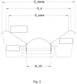
- the longest dimension of the surround and diaphragm unit in a direction perpendicular to the movement axis is D_clamp and is in the range 50 to 200 mm.
- a Young's modulus of the material of the diaphragm and the surround is in the range 2 to 15 GPa, or even 8 to 15 GPa.
- the thickness of the material of the diaphragm and the surround is in the range 0.03 to 1 mm, for example 0.03 to 0.6 mm.
- Such a loudspeaker assembly configuration allows for piston-like movement of the diaphragm and desirable sound output.
- the present invention provides loudspeakers with a relatively large axial stiffness and relatively low moving mass. This can lead to them having a high resonance frequency.
- Typical values for embodiments in which D_clamp is in the range of 100mm to 150mm are within the octave of 400Hz to 800Hz.
- the resonance frequency may be tuned to the frequency range where the fundamentals of the horns lie (typically 400 to 600Hz), decreasing the real power at the speaker in this range due to the impedance peak around resonance.
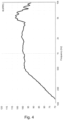
- the output at lower frequencies such as the 315Hz 1/3rd octave band is still substantial due to the high loudspeaker sensitivity (see Figure 4 ).
- a loudspeaker assembly for use outdoors is intended to refer to a loudspeaker assembly suitable for use (preferably configured for use) with at least part of the loudspeaker assembly exposed to the open air, i.e. not inside a shelter, vehicle or building; for example, on the outside of a vehicle.
- the frame may be in the form of a box which is acoustically sealed except for the loudspeaker or diaphragm covering one side of it.
- the thickness of the material of the diaphragm and surround may suitably be in the range 0.03 to 0.6 mm, preferably 0.05 to 0.3 mm, and more preferably in the range 0.1 to 0.2 mm.
- the thickness of the material corresponds to its smallest dimension, which may be broadly in the direction parallel to the movement axis (dependent on shape).
- the Young's modulus of the material of the diaphragm and surround is also found to be a relevant factor in optimising piston-like movement, in combination with the other factors considered here.
- the Young's modulus of the material of the diaphragm and surround may suitably be in the range 2 to 15 GPa, preferably in the range 8 to 15 GPa and more preferably in the range 10 to 12 GPa.
- the Young's modulus may vary depending on the direction of measurement. Accordingly in some embodiments that material has the Young's modulus mentioned above in at least one direction; and in some embodiments in all directions.
- the Young's modulus and tensile strength of the diaphragm material for a loudspeaker of the present invention may for example be determined by measurements according to ISO 527-1 from cut samples of the rectangular size 30mm x 5.3mm of the manufactured diaphragm. A first sample cut with warp and weft aligning with the cut direction and a second sample cut with warp and weft at 45° relative to the cut direction.
- the Young's modulus of the first cut sample where warp and weft are parallel to the edges of the rectangular sample is preferably in the range of 2 GPa to 15 GPa, more preferably in the range of 3 GPa to 10 GPa, more preferably in the range of 3 Gpa to 8 GPa.
- the ultimate tensile strength is suitably in the range of 75 MPa to 300 MPa, preferably in the range 100 MPa to 250MPa, more preferably in the range of 175 MPa to 225 Mpa.
- the elongation at break for any sample is suitably no more than 40% strain, preferably no more than 20% strain, more preferably no more than 10% strain.
- the most suitable materials are thermally stable with a substantially flat DSC curve over a temperature range of -40 °C to 300 °C. Ideally there shall be no condition change indicating melting, crystallization or glass transition.
- the Storage Modulus E' of any sample of a suitable material is suitably substantially stable over a temperature range from -40°C to 100 °C.
- the Storage Modulus is suitably in the range of 2 GPa to 10 GPa, preferably in the range of 4 GPa to 6 GPa.
- the Loss Modulus E" at room temperature is suitably no more than 1 GPa, preferably no more than 500 MPa, more preferably no more than 200 MPa.
- Suitable materials for the diaphragm and surround include materials comprising a single layer woven fabric of orthogonal, woven fibers such as glass fiber, carbon fiber or poly-paraphenylene terephthalamide (Kevlar) and a matrix or coating of thermoset resin such as epoxy or phenolic resin.
- a single layer woven fabric of orthogonal, woven fibers such as glass fiber, carbon fiber or poly-paraphenylene terephthalamide (Kevlar) and a matrix or coating of thermoset resin such as epoxy or phenolic resin.
- the weaving pattern is preferably a canvas or twill, and may suitably use the same thread count for the warp and the weft. That thread count may be, for example, 20-100 threads per inch (tpi), and preferably is 30-60 tpi.
- the material of the diaphragm and surround may suitably have a specific mass in the range 50g/m 2 to 500g/m 2 , and it may preferably be in the range 100g/m 2 to 300g/m 2 . Moreover, it may suitably have a bulk density in the range 1.2g/cm 3 to 1.8g/cm 3 , and preferably 1.4g/cm 3 to 1.6g/cm 3 .
- the diaphragm and surround are made of a single piece of material (that is, are unitary), there may be some manufacturing variation in properties of that material across the diaphragm and surround.
- the material has a substantially uniform or homogenous thickness and Young's modulus.
- the diaphragm may have a dished shape.
- the diaphragm may include a cone-shaped portion which is substantially in the shape of an open cone and has a cone opening angle in the range 60° to 160°. As an open cone, this means what would be the 'tip' of the cone is missing. Accordingly the cone opening angle is measured as the angle between the side walls of the cone-shaped portion. Preferably the cone opening angle is in the range 90° to 130°. It will be recognised that preferably those side walls of the cone-shaped portion are straight/flat; that is, that the cone angle does not vary in the radial direction.
- the cone-shaped portion may have a longest dimension in a direction perpendicular to the movement axis D_cone in the range 40mm to 180mm.
- the diaphragm may have a shaped portion which is adapted to engage the voice coil.
- a shoulder or indentation in the conical portion, at a position corresponding to where the voice coil will engage the diaphragm (in general terms, at D_VC).
- This shoulder or indentation may be annular, or another shape to match the voice coil (or at least the shape of the part of the voice coil that will engage the diaphragm). This allows for easier positioning of the voice coil, and easier adhesion/bonding/connection of it to the diaphragm as the shoulder/indentation acts as a siting or guiding portion.
- the diaphragm may further comprise a dust cap portion on the front face of the diaphragm covering the tip of the open cone of the cone-shaped portion.
- the dust cap is in such cases made from the same material as the surround and diaphragm, and is generally unitary with them, i.e. formed from the same single piece of material (and thus subject to the above mentioned preferences and features of that material).
- the corrugation may preferably have a curved cross section (in a section parallel to the movement axis), in particular a curve that is a section of a circle, and be tangentially connected to the radially adjacent feature, for example here the diaphragm. That is, the connection of the corrugation to the diaphragm is at a point where the wall of the diaphragm (such as the side wall of the cone shaped portion discussed above) is in a direction tangential to the theoretical circle of which the curved corrugation is a section. This affords a smooth transition between the corrugation and the diaphragm.
- the membrane movement can be regarded as being fundamentally that of a piston up to the diameter D_d and S_d according to (https://www.klippel.de/fileadmin/klippel/Files/Know How/Application Notes/AN 32 Effective Radiation_ Area.pdf). From the diameter D_d the loudspeaker parameter S_d is calculated. The ratio of D_d over D_clamp is no less than 0.8.
- corrugations are present.
- Each may independently be convex or concave with respect to the forward direction.
- the corrugations alternate between convex and concave.
- the loudspeaker assembly for example the diaphragm, surround, and driver, may be configured such that the extent of movement of the diaphragm along the movement axis, when the loudspeaker assembly is in use, is small.
- the maximum displacement of the diaphragm (one extremity of movement to the other) may be at most 2 mm. This may be, for example, the resting position of the diaphragm ⁇ at most 1mm, more preferably ⁇ at most 0.5mm.
- the surround may in some embodiments include a mounting portion at the perimeter of the surround, wherein the surround is attached onto the frame via the mounting portion.
- the mounting portion may be a flat annular portion around the perimeter of the surround. Generally it is formed as a unitary part of the surround. It may be attached to the frame by means such as an adhesive, or physically/mechanically held in place by, for example, a fixing member placed to sandwich the mounting portion between the fixing member and the frame.
- the break-up region is well understood in the art; it occurs where the primarily piston-like movement of the diaphragm breaks up.
- radial modal behaviour has a strong influence on the radiated sound pressure level as the areas of increased or decreased motion are not uniform in size. This leads to a dip and subsequent peaks in the frequency response - this is the break-up.
- the radial modal behaviour is determined by the material and shape but also the boundary condition.
- D_clamp, D_VC, D_cone and D_d each correspond to a diameter of the relevant circle.
- the loudspeaker assembly may further comprise a grille positioned in front of the front face of the diaphragm, with a rear face of the grille facing in the rearwards direction toward the front face of the diaphragm, and with a front face of the grille facing in the forwards direction; wherein the grille is configured to permit sound produced by the front face of the diaphragm to pass through the grille when the loudspeaker is in use, and to inhibit the ingress of water incident on the front face of the grille from entering into a space enclosed between the rear face of the grille and the front face of the diaphragm.
- the loudspeaker assembly may preferably be configured for use in a road vehicle with the front face of the grille exposed to an outdoor environment. It may form part of an Acoustic Vehicle Alerting System (AVAS), or an Audible Warning Device (horn).
- AVAS Acoustic Vehicle Alerting System
- horn Audible Warning Device
- the invention includes the combination of the aspects and preferred features described except where such a combination is clearly impermissible or expressly avoided.
- Figure 1 schematically illustrates the overarching concept of the present invention.
- Figure 1(b) shows a simple membrane formed from a homogenous material (solid line) which moves when actuated to the dotted line position. The membrane bends, changing shape and affecting its response. These are disadvantageous speaker behaviours.
- FIG. 1(a) shows the speaker motion enabled by the present invention.
- a loudspeaker assembly 1 is schematically illustrated.
- the part corresponding to the homogenous membrane is the broadly conical (open cone)-shaped diaphragm 3, which is bounded by a surround 7 and has a dust cap 9 integrally formed at its centre.
- the dust cap stops dust, particles and other matter from getting into the voice coil former and entering the voice coil region.
- the diaphragm and dust cap When actuated by the drive unit 2, which includes a voice coil 8, the diaphragm and dust cap move to the dotted line position, together and in phase: this is piston-like movement as described herein.
- the surround is part of a suspension 6, which broadly links the diaphragm 3 to a frame (not illustrated in Figure 1(a) ; later the numeral 14 is used).
- the piston-like movement occurs in a movement axis 4, with actuation of the voice coil and hence the diaphragm 3 moving it in what is herein referred to as a forwards direction, indicated by the arrow 5.
- a forwards direction indicated by the arrow 5.
- the axis 4 and direction 5 are merely indicative of the primary motion.
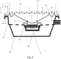
- the mounting portion 15 may be, for example, stuck to a ledge or platform part of the frame 14 by an adhesive. Alternatively it may be secured between the ledge/platform part 18 and a lid 19 of the unit. Such a mechanical clamping may be used in combination with an adhesive to fix the mounting portion 15 and hence the surround 7.
- Such a suspension arrangement can provide further flexibility to the surround 7; this may mean that different material properties can be exploited.
- the drive system 2 illustrated for this embodiment utilises a disc magnet 24. It is mounted to the frame 14; in this instance, the frame 14 is itself mounted to a rear part 25 forming a cabinet (as is the spider 20).
- the rear part 25 can be attached to the frame by any means, such as an adhesive or mechanical bonding such as screw fixtures.
- FIG. 9 A third example embodiment is illustrated in Figure 9 .
- the drive system here is comparable to that of Figure 8 , with a disc magnet 24 mounted within the frame 14 (no rear part 25 is present in this embodiment). This is fixed to the rear wall of the frame 14; no spider is present in this embodiment.
- the dust cap 9 is much as illustrated and explained for Figure 7 ; a similar notch 17 is present to seat the voice coil 8.
- the material of the diaphragm, surround and dust cap in this embodiment is epoxy coated glass fiber with a thickness of 0.15 mm.
- Figure 4 shows an example frequency response from a loudspeaker assembly of the present invention having a 0.15 mm thick material forming the diaphragm, surround and dust cap, made from glass fiber and epoxy resin, at 2V on axis in infinite baffle, without a grille. It can be seen that despite the high resonance frequency of speakers of the present invention, the output at lower frequencies such as the 315Hz 1/3rd octave band is still substantial (approximately 87 dB) due to the high loudspeaker sensitivity.
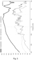
- Figure 5 shows an example frequency response and 2 nd and 3 rd order distortion components from a loudspeaker assembly of the present invention having a 0.15 mm thick material forming the diaphragm, surround and dust cap, made from glass fiber and epoxy resin, at 8.5V on axis in infinite baffle, with a grille. These Figures show that even at 8.5V the harmonic distortion remains moderate for low frequencies.
- Figure 6 shows an example frequency response from a loudspeaker assembly of the present invention with a 0.08mm thick material forming the diaphragm, surround and dust cap, made from Kevlar dipped in phenolic resin, at 2V on axis in infinite baffle, without a grille.
- the frequency response is substantially smooth within the decade ranging from 500Hz to 5kHz.
Landscapes
- Engineering & Computer Science (AREA)
- Multimedia (AREA)
- Physics & Mathematics (AREA)
- Acoustics & Sound (AREA)
- Signal Processing (AREA)
- Audible-Bandwidth Dynamoelectric Transducers Other Than Pickups (AREA)
- Diaphragms For Electromechanical Transducers (AREA)
- Fittings On The Vehicle Exterior For Carrying Loads, And Devices For Holding Or Mounting Articles (AREA)
- Obtaining Desirable Characteristics In Audible-Bandwidth Transducers (AREA)
- Details Of Audible-Bandwidth Transducers (AREA)
Applications Claiming Priority (3)
| Application Number | Priority Date | Filing Date | Title |
|---|---|---|---|
| GBGB2108015.5A GB202108015D0 (en) | 2021-06-04 | 2021-06-04 | Speaker |
| EP22734488.4A EP4349032B1 (de) | 2021-06-04 | 2022-06-01 | Lautsprecher |
| PCT/EP2022/064971 WO2022253924A1 (en) | 2021-06-04 | 2022-06-01 | Speaker |
Related Parent Applications (2)
| Application Number | Title | Priority Date | Filing Date |
|---|---|---|---|
| EP22734488.4A Division EP4349032B1 (de) | 2021-06-04 | 2022-06-01 | Lautsprecher |
| EP22734488.4A Division-Into EP4349032B1 (de) | 2021-06-04 | 2022-06-01 | Lautsprecher |
Publications (2)
| Publication Number | Publication Date |
|---|---|
| EP4513896A2 true EP4513896A2 (de) | 2025-02-26 |
| EP4513896A3 EP4513896A3 (de) | 2025-06-04 |
Family
ID=76838740
Family Applications (2)
| Application Number | Title | Priority Date | Filing Date |
|---|---|---|---|
| EP25151587.0A Pending EP4513896A3 (de) | 2021-06-04 | 2022-06-01 | Lautsprecher |
| EP22734488.4A Active EP4349032B1 (de) | 2021-06-04 | 2022-06-01 | Lautsprecher |
Family Applications After (1)
| Application Number | Title | Priority Date | Filing Date |
|---|---|---|---|
| EP22734488.4A Active EP4349032B1 (de) | 2021-06-04 | 2022-06-01 | Lautsprecher |
Country Status (5)
| Country | Link |
|---|---|
| US (3) | US12452599B2 (de) |
| EP (2) | EP4513896A3 (de) |
| CN (2) | CN120264202A (de) |
| GB (1) | GB202108015D0 (de) |
| WO (1) | WO2022253924A1 (de) |
Families Citing this family (6)
| Publication number | Priority date | Publication date | Assignee | Title |
|---|---|---|---|---|
| EP4473527A1 (de) | 2022-12-02 | 2024-12-11 | PSS Belgium NV | Hornvorrichtungen und zugehörige verfahren |
| CN218750537U (zh) * | 2022-12-02 | 2023-03-28 | 苏州上声电子股份有限公司 | 一种汽车行人警示装置 |
| CN221306102U (zh) * | 2023-12-01 | 2024-07-09 | 苏州上声电子股份有限公司 | 一种发声装置及汽车行人警示器 |
| GB202410750D0 (en) | 2024-07-23 | 2024-09-04 | Pss Belgium Nv | Loudspeaker assembly |
| GB202415168D0 (en) | 2024-10-15 | 2024-11-27 | Pss Belgium Nv | Vehicle and horn apparatus for vehicle |
| GB202415167D0 (en) * | 2024-10-15 | 2024-11-27 | Pss Belgium Nv | Vehicle and forn apparatus for vehicle |
Citations (4)
| Publication number | Priority date | Publication date | Assignee | Title |
|---|---|---|---|---|
| US8217767B2 (en) | 2010-06-09 | 2012-07-10 | Denso Corporation | Vehicle presence notification apparatus |
| FR2983025A1 (fr) | 2011-11-23 | 2013-05-24 | Peugeot Citroen Automobiles Sa | Systeme de generation de son exterieur pour vehicules automobiles |
| US10406976B2 (en) | 2018-01-31 | 2019-09-10 | Ford Global Technologies, Llc | Multi-purpose automotive sound device |
| US20200070719A1 (en) | 2017-03-15 | 2020-03-05 | Audi Ag | Acoustic Vehicle Warning System for a Motor Vehicle Having an Integrated Function for Outputting Acoustic Warning Signals |
Family Cites Families (31)
| Publication number | Priority date | Publication date | Assignee | Title |
|---|---|---|---|---|
| BE482081A (de) | 1945-11-08 | |||
| AT274080B (de) | 1967-07-05 | 1969-09-10 | Philips Nv | Schallwandler mit einer Schaumstoffmembran |
| US3862376A (en) | 1973-01-19 | 1975-01-21 | Stanley F White | Cone construction for loudspeaker |
| GB1491080A (en) | 1975-03-15 | 1977-11-09 | B & W Loudspeakers | Loudspeakers |
| US4312118A (en) | 1980-03-28 | 1982-01-26 | Cts Corporation | Method for producing speaker construction |
| JPH0634560B2 (ja) | 1989-12-07 | 1994-05-02 | オンキヨー株式会社 | スピーカ用ドーム状部材の製造方法 |
| JPH06165289A (ja) * | 1992-11-27 | 1994-06-10 | Matsushita Electric Ind Co Ltd | スピーカ用振動板及びその製造方法 |
| GB2315185A (en) | 1996-07-09 | 1998-01-21 | B & W Loudspeakers | Diaphragm surrounds for loudspeaker drive units |
| JP4864193B2 (ja) | 2000-07-19 | 2012-02-01 | オンキヨー株式会社 | スピーカー用部材およびその製造方法 |
| JP4557412B2 (ja) | 2000-11-20 | 2010-10-06 | パナソニック株式会社 | スピーカ |
| JP4447818B2 (ja) | 2002-01-25 | 2010-04-07 | オンキヨー株式会社 | スピーカー用振動板 |
| FR2859864B1 (fr) | 2003-09-15 | 2005-12-30 | Cabasse Acoustic Ct | Haut-parleur et enceinte acoustique correspondante |
| JP4795712B2 (ja) | 2005-04-21 | 2011-10-19 | パイオニア株式会社 | スピーカー装置用振動系部品及びその製造方法 |
| MX2009000055A (es) | 2006-07-12 | 2009-01-23 | Anders Sagren | Conjunto de diafragma de alta frecuencia y bobina de voz. |
| JP4855213B2 (ja) | 2006-10-24 | 2012-01-18 | アルパイン株式会社 | スピーカ |
| WO2010023759A1 (ja) | 2008-08-29 | 2010-03-04 | パイオニア株式会社 | スピーカ装置 |
| JP5254119B2 (ja) * | 2009-04-21 | 2013-08-07 | オンキヨー株式会社 | スピーカー |
| EP2271137A1 (de) | 2009-07-03 | 2011-01-05 | DR. KURT MÜLLER GmbH & Co. KG | Lautsprechermembran und Verfahren zur Herstellung einer Lautsprechermembran |
| US9014412B2 (en) | 2010-07-09 | 2015-04-21 | Aperion Audio, Inc. | Loudspeaker that is axially stabilized out of the diaphragm suspension plane |
| JP2012153303A (ja) | 2011-01-27 | 2012-08-16 | Denso Corp | 車両接近通報装置 |
| JP2013198069A (ja) | 2012-03-22 | 2013-09-30 | Yamaha Corp | 電気音響変換装置の振動板、およびその製造方法 |
| JP2013201484A (ja) * | 2012-03-23 | 2013-10-03 | Yamaha Corp | スピーカ用振動板 |
| JP6244540B2 (ja) | 2013-05-09 | 2017-12-13 | パナソニックIpマネジメント株式会社 | スピーカシステムと、これを用いた移動体装置 |
| CN103686547A (zh) | 2013-12-09 | 2014-03-26 | 歌尔声学股份有限公司 | 一种扬声器振膜及其制造方法 |
| CN109565623B (zh) | 2016-09-01 | 2021-05-11 | 松下知识产权经营株式会社 | 扬声器装置和搭载有该扬声器装置的移动体装置 |
| CN109691131A (zh) | 2016-09-13 | 2019-04-26 | 松下知识产权经营株式会社 | 扬声器用振动板及其制造方法以及使用了该扬声器用振动板的扬声器 |
| JP6275297B1 (ja) | 2017-01-31 | 2018-02-07 | アルパイン株式会社 | 音響装置 |
| CN208585167U (zh) | 2018-08-08 | 2019-03-08 | 苏州上声电子股份有限公司 | 一种带网罩的行人警示器 |
| JP7181046B2 (ja) | 2018-10-17 | 2022-11-30 | フォスター電機株式会社 | 電気音響変換器用振動板 |
| GB201907610D0 (en) | 2019-05-29 | 2019-07-10 | Pss Belgium Nv | Loudspeaker |
| CN114762362A (zh) | 2019-11-15 | 2022-07-15 | 株式会社可乐丽 | 音响振动板及其制造方法以及音响设备 |
-
2021
- 2021-06-04 GB GBGB2108015.5A patent/GB202108015D0/en not_active Ceased
-
2022
- 2022-06-01 CN CN202510394929.5A patent/CN120264202A/zh active Pending
- 2022-06-01 WO PCT/EP2022/064971 patent/WO2022253924A1/en not_active Ceased
- 2022-06-01 EP EP25151587.0A patent/EP4513896A3/de active Pending
- 2022-06-01 US US18/566,866 patent/US12452599B2/en active Active
- 2022-06-01 EP EP22734488.4A patent/EP4349032B1/de active Active
- 2022-06-01 CN CN202280039459.5A patent/CN117413533A/zh active Pending
-
2024
- 2024-07-12 US US18/771,637 patent/US12452600B2/en active Active
-
2025
- 2025-08-22 US US19/307,902 patent/US20250373983A1/en active Pending
Patent Citations (4)
| Publication number | Priority date | Publication date | Assignee | Title |
|---|---|---|---|---|
| US8217767B2 (en) | 2010-06-09 | 2012-07-10 | Denso Corporation | Vehicle presence notification apparatus |
| FR2983025A1 (fr) | 2011-11-23 | 2013-05-24 | Peugeot Citroen Automobiles Sa | Systeme de generation de son exterieur pour vehicules automobiles |
| US20200070719A1 (en) | 2017-03-15 | 2020-03-05 | Audi Ag | Acoustic Vehicle Warning System for a Motor Vehicle Having an Integrated Function for Outputting Acoustic Warning Signals |
| US10406976B2 (en) | 2018-01-31 | 2019-09-10 | Ford Global Technologies, Llc | Multi-purpose automotive sound device |
Also Published As
| Publication number | Publication date |
|---|---|
| US20240373168A1 (en) | 2024-11-07 |
| US20250373983A1 (en) | 2025-12-04 |
| US12452599B2 (en) | 2025-10-21 |
| CN120264202A (zh) | 2025-07-04 |
| WO2022253924A1 (en) | 2022-12-08 |
| EP4513896A3 (de) | 2025-06-04 |
| GB202108015D0 (en) | 2021-07-21 |
| US12452600B2 (en) | 2025-10-21 |
| EP4349032B1 (de) | 2025-02-19 |
| EP4349032A1 (de) | 2024-04-10 |
| CN117413533A (zh) | 2024-01-16 |
| US20240276151A1 (en) | 2024-08-15 |
Similar Documents
| Publication | Publication Date | Title |
|---|---|---|
| EP4349032B1 (de) | Lautsprecher | |
| AU2008352372B2 (en) | Nested compound loudspeaker drive unit | |
| US20030081800A1 (en) | Flat panel sound radiator with supported exciter and compliant surround | |
| US10623840B2 (en) | Loudspeaker acoustic diversity aperture frame | |
| US12395786B2 (en) | Loudspeaker | |
| CN120303730A (zh) | 喇叭装置及相关方法 | |
| US12574686B2 (en) | Loudspeaker assembly | |
| WO2025113631A1 (zh) | 发声装置及车辆行人警示器 | |
| KR100490787B1 (ko) | 차량용 스피커 | |
| US7570774B2 (en) | Speaker having improved sound-radiating function to both directions | |
| US4427846A (en) | Moving coil loudspeakers | |
| US12200420B2 (en) | Microphone assembly, filter for microphone, process for assembly and manufacturing microphone and filter for microphone, and method for filtering microphone | |
| KR200337835Y1 (ko) | 소형 스피커 유닛용 진동판 | |
| JP3245074B2 (ja) | ダブルドーム振動板及びそれを用いたスピーカー | |
| GB2516936A (en) | Loudspeaker driver | |
| CN223666479U (zh) | 一种扬声器 | |
| US20260134861A1 (en) | Horn apparatuses and associated methods | |
| WO2026082417A1 (en) | Vehicle and horn apparatus for vehicle | |
| WO2026082418A1 (en) | Vehicle and horn apparatus for vehicle | |
| GB2070389A (en) | Electroacoustic transducer | |
| JP2005322987A (ja) | 複合型スピーカ装置 | |
| HK40005218A (en) | Loudspeaker | |
| JP2000041297A (ja) | スピーカ装置 | |
| US20100177920A1 (en) | A micro-speaker | |
| CA2177400A1 (en) | Thin full range speaker system |
Legal Events
| Date | Code | Title | Description |
|---|---|---|---|
| PUAI | Public reference made under article 153(3) epc to a published international application that has entered the european phase |
Free format text: ORIGINAL CODE: 0009012 |
|
| STAA | Information on the status of an ep patent application or granted ep patent |
Free format text: STATUS: THE APPLICATION HAS BEEN PUBLISHED |
|
| AC | Divisional application: reference to earlier application |
Ref document number: 4349032 Country of ref document: EP Kind code of ref document: P |
|
| AK | Designated contracting states |
Kind code of ref document: A2 Designated state(s): AL AT BE BG CH CY CZ DE DK EE ES FI FR GB GR HR HU IE IS IT LI LT LU LV MC MK MT NL NO PL PT RO RS SE SI SK SM TR |
|
| REG | Reference to a national code |
Ref country code: DE Ref legal event code: R079 Free format text: PREVIOUS MAIN CLASS: H04R0007180000 Ipc: H04R0007120000 |
|
| PUAL | Search report despatched |
Free format text: ORIGINAL CODE: 0009013 |
|
| AK | Designated contracting states |
Kind code of ref document: A3 Designated state(s): AL AT BE BG CH CY CZ DE DK EE ES FI FR GB GR HR HU IE IS IT LI LT LU LV MC MK MT NL NO PL PT RO RS SE SI SK SM TR |
|
| RIC1 | Information provided on ipc code assigned before grant |
Ipc: H04R 7/18 20060101ALI20250425BHEP Ipc: H04R 7/12 20060101AFI20250425BHEP |
|
| STAA | Information on the status of an ep patent application or granted ep patent |
Free format text: STATUS: REQUEST FOR EXAMINATION WAS MADE |
|
| 17P | Request for examination filed |
Effective date: 20250721 |