EP4513630A1 - Kühlmodul und batterietrennvorrichtung damit - Google Patents
Kühlmodul und batterietrennvorrichtung damit Download PDFInfo
- Publication number
- EP4513630A1 EP4513630A1 EP23792034.3A EP23792034A EP4513630A1 EP 4513630 A1 EP4513630 A1 EP 4513630A1 EP 23792034 A EP23792034 A EP 23792034A EP 4513630 A1 EP4513630 A1 EP 4513630A1
- Authority
- EP
- European Patent Office
- Prior art keywords
- heat dissipation
- pipe
- heat
- coupling portion
- cooling module
- Prior art date
- Legal status (The legal status is an assumption and is not a legal conclusion. Google has not performed a legal analysis and makes no representation as to the accuracy of the status listed.)
- Pending
Links
Images


Classifications
-
- H—ELECTRICITY
- H01—ELECTRIC ELEMENTS
- H01M—PROCESSES OR MEANS, e.g. BATTERIES, FOR THE DIRECT CONVERSION OF CHEMICAL ENERGY INTO ELECTRICAL ENERGY
- H01M10/00—Secondary cells; Manufacture thereof
- H01M10/60—Heating or cooling; Temperature control
- H01M10/66—Heat-exchange relationships between the cells and other systems, e.g. central heating systems or fuel cells
- H01M10/667—Heat-exchange relationships between the cells and other systems, e.g. central heating systems or fuel cells the system being an electronic component, e.g. a CPU, an inverter or a capacitor
-
- B—PERFORMING OPERATIONS; TRANSPORTING
- B60—VEHICLES IN GENERAL
- B60L—PROPULSION OF ELECTRICALLY-PROPELLED VEHICLES; SUPPLYING ELECTRIC POWER FOR AUXILIARY EQUIPMENT OF ELECTRICALLY-PROPELLED VEHICLES; ELECTRODYNAMIC BRAKE SYSTEMS FOR VEHICLES IN GENERAL; MAGNETIC SUSPENSION OR LEVITATION FOR VEHICLES; MONITORING OPERATING VARIABLES OF ELECTRICALLY-PROPELLED VEHICLES; ELECTRIC SAFETY DEVICES FOR ELECTRICALLY-PROPELLED VEHICLES
- B60L53/00—Methods of charging batteries, specially adapted for electric vehicles; Charging stations or on-board charging equipment therefor; Exchange of energy storage elements in electric vehicles
- B60L53/30—Constructional details of charging stations
- B60L53/302—Cooling of charging equipment
-
- H—ELECTRICITY
- H01—ELECTRIC ELEMENTS
- H01M—PROCESSES OR MEANS, e.g. BATTERIES, FOR THE DIRECT CONVERSION OF CHEMICAL ENERGY INTO ELECTRICAL ENERGY
- H01M10/00—Secondary cells; Manufacture thereof
- H01M10/60—Heating or cooling; Temperature control
- H01M10/61—Types of temperature control
- H01M10/613—Cooling or keeping cold
-
- H—ELECTRICITY
- H01—ELECTRIC ELEMENTS
- H01M—PROCESSES OR MEANS, e.g. BATTERIES, FOR THE DIRECT CONVERSION OF CHEMICAL ENERGY INTO ELECTRICAL ENERGY
- H01M10/00—Secondary cells; Manufacture thereof
- H01M10/60—Heating or cooling; Temperature control
- H01M10/62—Heating or cooling; Temperature control specially adapted for specific applications
- H01M10/625—Vehicles
-
- H—ELECTRICITY
- H01—ELECTRIC ELEMENTS
- H01M—PROCESSES OR MEANS, e.g. BATTERIES, FOR THE DIRECT CONVERSION OF CHEMICAL ENERGY INTO ELECTRICAL ENERGY
- H01M10/00—Secondary cells; Manufacture thereof
- H01M10/60—Heating or cooling; Temperature control
- H01M10/65—Means for temperature control structurally associated with the cells
- H01M10/651—Means for temperature control structurally associated with the cells characterised by parameters specified by a numeric value or mathematical formula, e.g. ratios, sizes or concentrations
-
- H—ELECTRICITY
- H01—ELECTRIC ELEMENTS
- H01M—PROCESSES OR MEANS, e.g. BATTERIES, FOR THE DIRECT CONVERSION OF CHEMICAL ENERGY INTO ELECTRICAL ENERGY
- H01M10/00—Secondary cells; Manufacture thereof
- H01M10/60—Heating or cooling; Temperature control
- H01M10/65—Means for temperature control structurally associated with the cells
- H01M10/653—Means for temperature control structurally associated with the cells characterised by electrically insulating or thermally conductive materials
-
- H—ELECTRICITY
- H01—ELECTRIC ELEMENTS
- H01M—PROCESSES OR MEANS, e.g. BATTERIES, FOR THE DIRECT CONVERSION OF CHEMICAL ENERGY INTO ELECTRICAL ENERGY
- H01M10/00—Secondary cells; Manufacture thereof
- H01M10/60—Heating or cooling; Temperature control
- H01M10/65—Means for temperature control structurally associated with the cells
- H01M10/655—Solid structures for heat exchange or heat conduction
- H01M10/6551—Surfaces specially adapted for heat dissipation or radiation, e.g. fins or coatings
-
- H—ELECTRICITY
- H01—ELECTRIC ELEMENTS
- H01M—PROCESSES OR MEANS, e.g. BATTERIES, FOR THE DIRECT CONVERSION OF CHEMICAL ENERGY INTO ELECTRICAL ENERGY
- H01M10/00—Secondary cells; Manufacture thereof
- H01M10/60—Heating or cooling; Temperature control
- H01M10/65—Means for temperature control structurally associated with the cells
- H01M10/655—Solid structures for heat exchange or heat conduction
- H01M10/6553—Terminals or leads
-
- H—ELECTRICITY
- H01—ELECTRIC ELEMENTS
- H01M—PROCESSES OR MEANS, e.g. BATTERIES, FOR THE DIRECT CONVERSION OF CHEMICAL ENERGY INTO ELECTRICAL ENERGY
- H01M10/00—Secondary cells; Manufacture thereof
- H01M10/60—Heating or cooling; Temperature control
- H01M10/65—Means for temperature control structurally associated with the cells
- H01M10/655—Solid structures for heat exchange or heat conduction
- H01M10/6556—Solid parts with flow channel passages or pipes for heat exchange
-
- H—ELECTRICITY
- H01—ELECTRIC ELEMENTS
- H01M—PROCESSES OR MEANS, e.g. BATTERIES, FOR THE DIRECT CONVERSION OF CHEMICAL ENERGY INTO ELECTRICAL ENERGY
- H01M10/00—Secondary cells; Manufacture thereof
- H01M10/60—Heating or cooling; Temperature control
- H01M10/65—Means for temperature control structurally associated with the cells
- H01M10/656—Means for temperature control structurally associated with the cells characterised by the type of heat-exchange fluid
- H01M10/6567—Liquids
-
- H—ELECTRICITY
- H01—ELECTRIC ELEMENTS
- H01M—PROCESSES OR MEANS, e.g. BATTERIES, FOR THE DIRECT CONVERSION OF CHEMICAL ENERGY INTO ELECTRICAL ENERGY
- H01M50/00—Constructional details or processes of manufacture of the non-active parts of electrochemical cells other than fuel cells, e.g. hybrid cells
- H01M50/50—Current conducting connections for cells or batteries
- H01M50/502—Interconnectors for connecting terminals of adjacent batteries; Interconnectors for connecting cells outside a battery casing
- H01M50/507—Interconnectors for connecting terminals of adjacent batteries; Interconnectors for connecting cells outside a battery casing comprising an arrangement of two or more busbars within a container structure, e.g. busbar modules
-
- H—ELECTRICITY
- H01—ELECTRIC ELEMENTS
- H01M—PROCESSES OR MEANS, e.g. BATTERIES, FOR THE DIRECT CONVERSION OF CHEMICAL ENERGY INTO ELECTRICAL ENERGY
- H01M50/00—Constructional details or processes of manufacture of the non-active parts of electrochemical cells other than fuel cells, e.g. hybrid cells
- H01M50/50—Current conducting connections for cells or batteries
- H01M50/572—Means for preventing undesired use or discharge
- H01M50/574—Devices or arrangements for the interruption of current
-
- F—MECHANICAL ENGINEERING; LIGHTING; HEATING; WEAPONS; BLASTING
- F28—HEAT EXCHANGE IN GENERAL
- F28F—DETAILS OF HEAT-EXCHANGE AND HEAT-TRANSFER APPARATUS, OF GENERAL APPLICATION
- F28F3/00—Plate-like or laminated elements; Assemblies of plate-like or laminated elements
- F28F3/02—Elements or assemblies thereof with means for increasing heat-transfer area, e.g. with fins, with recesses, with corrugations
- F28F3/04—Elements or assemblies thereof with means for increasing heat-transfer area, e.g. with fins, with recesses, with corrugations the means being integral with the element
- F28F3/048—Elements or assemblies thereof with means for increasing heat-transfer area, e.g. with fins, with recesses, with corrugations the means being integral with the element in the form of ribs integral with the element or local variations in thickness of the element, e.g. grooves, microchannels
-
- H—ELECTRICITY
- H01—ELECTRIC ELEMENTS
- H01M—PROCESSES OR MEANS, e.g. BATTERIES, FOR THE DIRECT CONVERSION OF CHEMICAL ENERGY INTO ELECTRICAL ENERGY
- H01M2220/00—Batteries for particular applications
- H01M2220/20—Batteries in motive systems, e.g. vehicle, ship, plane
-
- Y—GENERAL TAGGING OF NEW TECHNOLOGICAL DEVELOPMENTS; GENERAL TAGGING OF CROSS-SECTIONAL TECHNOLOGIES SPANNING OVER SEVERAL SECTIONS OF THE IPC; TECHNICAL SUBJECTS COVERED BY FORMER USPC CROSS-REFERENCE ART COLLECTIONS [XRACs] AND DIGESTS
- Y02—TECHNOLOGIES OR APPLICATIONS FOR MITIGATION OR ADAPTATION AGAINST CLIMATE CHANGE
- Y02E—REDUCTION OF GREENHOUSE GAS [GHG] EMISSIONS, RELATED TO ENERGY GENERATION, TRANSMISSION OR DISTRIBUTION
- Y02E60/00—Enabling technologies; Technologies with a potential or indirect contribution to GHG emissions mitigation
- Y02E60/10—Energy storage using batteries
Definitions
- the present disclosure relates to a cooling module and a battery disconnect device including the same, and more particularly, to a cooling module and a battery disconnect device with a structure that is simply assembled and has improved cooling efficiency.
- EVs, HEVs, HVs, etc. as described above are essentially equipped with batteries which supply electricity to drive the vehicles.
- a battery disconnect unit BDU
- the battery As a vehicle and a battery that drives the vehicle continue to operate, high heat is generated in a battery disconnect unit (BDU), which is densely packed with the battery and devices for opening and closing the battery and loads, for example, switches, etc. If the generated high heat is left as it is, there is a possibility that the battery, the BDU, or various components disposed in the vehicle may be damaged.
- BDU battery disconnect unit
- Widely used methods for cooling batteries may be classified into air cooling and water cooling.
- an amount of heat generated from a battery is not excessive, so sufficient cooling efficiency can be expected merely by air cooling.
- EVs, HEVs, HVs, etc. having batteries that emit high heat generally adopt water cooling because it is difficult to cool such batteries sufficiently with air cooling alone.
- Korean Patent Registration No. 10-1971884 discloses a cooling pad and an electric vehicle using the same. Specifically, the patent document discloses a cooling pad capable of cooling an external heat source by receiving refrigerant from a cooling system of an electric vehicle, and an electric vehicle using the same.
- Korean Patent Application Publication No. 10-2012-0129076 discloses a cooling system for an electric vehicle. Specifically, a cooling system for an electric vehicle is disclosed to achieve miniaturization and weight reduction of a cooling module package by simplifying a cooling passage through improvement of disposition between devices.
- Another aspect of the present disclosure is to provide a cooling module with a structure that is capable of stably ensuring electrical insulation from electrical devices coupled thereto, and a battery disconnect device including the same.
- Still another aspect of the present disclosure is to provide a cooling module with a structure that is capable of improving manufacturing efficiency, and a battery disconnect device including the same.
- Another aspect of the present disclosure is to provide a cooling module with a structure that is capable of suppressing loss of cooling medium, and a battery disconnect device including the same.
- Another aspect of the present disclosure is to provide a cooling module with a structure that is applicable to electrical devices of various sizes, and a battery disconnect device including the same.
- a cooling module that includes: a heat dissipation part that is coupled to an external busbar and receives heat from the busbar; and a pipe part that is coupled to the heat dissipation part and in which a heat transfer medium receiving the heat flows, wherein the heat dissipation part includes: a heat dissipation body that extends in one direction; a pipe coupling portion that extends along the one direction inside the heat dissipation body, and has each end portion in the one direction open such that the pipe part is coupled therethrough; and a busbar coupling portion that is located adjacent to the pipe coupling portion and to which the busbar is coupled.
- the cooling module in which the heat dissipation part is made of thermal conductive plastic or thermal conductive rubber.
- the cooling module in which the heat dissipation part is formed of a material having thermal conductivity of 0.5 W/mK or more.
- the cooling module in which the heat dissipation part is formed of a material having thermal conductivity of 2.0 W/mK or more.
- the cooling module in which the heat dissipation part and the pipe part are manufactured by insert-molding.
- the cooling module in which the heat dissipation part comprises a fin member that is located on one side of the heat dissipation body to be opposite to the busbar coupling portion, and protrudes externally to increase a surface area.
- the cooling module in which the fin member is provided in plurality, and the plurality of fin members are disposed to be spaced apart from one another in the one direction.
- the cooling module in which the pipe part is formed such that a shape of a cross-section of each end portion in an extending direction thereof is different from a shape of a cross-section of a portion between the end portions, and the end portions are exposed to outside of the heat dissipation body while the portion between the end portions is accommodated in the pipe coupling portion.
- the cooling module in which the shape of the cross-section of each end portion of the pipe part is circular, and the shape of the cross-section of the portion between the end portions is formed in a plate shape with a thickness smaller than a diameter of the cross-section of each end portion.
- the cooling module that further includes a heat transfer part that is coupled to each of the heat dissipation part and the pipe part and is configured to exchange heat with the heat dissipation part and the pipe part, and in which the heat dissipation part includes a transfer coupling portion that extends along the one direction inside the heat dissipation body, is located between the busbar coupling portion and the pipe coupling portion, and accommodates the heat transfer part.
- the cooling module in which the heat transfer part includes: a transfer body that extends along the one direction and is in contact with the heat dissipation body to exchange heat; and a pipe accommodating portion that is recessed in one surface of the transfer body and extends along the one direction to accommodate the pipe part, and the pipe part is in contact with a surface, surrounding the pipe accommodating portion, of surfaces of the transfer body, so as to exchange heat.
- a cooling module that includes: a heat dissipation part that is coupled to an external busbar and receives heat from the busbar; and a pipe part that is coupled to the heat dissipation part and in which a heat transfer medium receiving the heat flows, wherein the heat dissipation part includes: a heat dissipation body that extends in one direction to surround one side of the pipe part; a pipe coupling portion that is located on one surface of the heat dissipation body, extends along the one direction by a length shorter than the heat dissipation body, and surrounds another side of the pipe part; and a heat dissipation opening that is formed through the pipe coupling portion to form a passage through which the pipe part is exposed to outside.
- a battery disconnect device that includes: a plurality of contactors each of which is electrically connected to an external power source and an external load and that are disposed side by side in one direction; a plurality of busbars that are electrically connected to the plurality of contactors, respectively; a heat dissipation part that is coupled to the plurality of busbars and receives heat from the busbars; and a pipe part that is coupled to the heat dissipation part and in which a heat transfer medium receiving the heat flows, wherein the heat dissipation part includes: a heat dissipation body that extends in the one direction; a pipe coupling portion that extends along the one direction inside the heat dissipation body, and has each end portion in the one direction open such that the pipe part is coupled therethrough; and a plurality of busbar coupling portions that are formed on the heat dissipation body, and located adjacent to the pipe coupling portion, and to which the plurality
- a battery disconnect device in which the external power source is a battery disposed in an electric vehicle.
- the cooling module includes a heat dissipation part made of a thermally conductive plastic material or a thermally conductive rubber material.
- the heat dissipation part is located adjacent to a busbar to receive heat generated from the busbar.
- a pipe part through which a heat transfer medium flows is coupled to the heat dissipation part.
- the pipe part may communicate with outside so that a low-temperature heat transfer medium can be introduced therein.
- the pipe part may communicate with the outside such that high-temperature heat transfer medium that has received generated heat can flow out.
- the heat transfer medium may be water, which has a higher heat capacity than air.
- the cooling module may be configured to cool the configuration of the battery disconnect device by water cooling.
- a heat transfer part that is coupled to the pipe part and exchanges heat may be provided.
- the heat transfer part is made of a material with high thermal conductivity, receives heat generated from the busbar, and transfers the received heat to the pipe part.
- electrical insulation can be stably secured between the cooling module and the battery disconnect device including the same according to an embodiment of the present disclosure and the electrical device.
- manufacturing efficiency of the cooling module and the battery disconnect device including the same according to an embodiment of the present disclosure can be improved.
- the cooling module may include the heat dissipation part and the pipe part. At this time, the volume of the cooling module can be reduced by a volume corresponding to a space occupied by the heat transfer part.
- communication means that one or more members communicate with each other so that a fluid can flow therethrough.
- the communication may be implemented by a member such as a conduit, pipe, or piping.
- electrical connection or current application refers to that one or more members are connected such that current or an electrical signal can be transmitted therebetween.
- the electrical connection may be made in a wired form using a conductor member, or in a wireless form such as Bluetooth, Wi-Fi, or RFID.
- the battery disconnect device 1 may be disposed in any vehicle equipped with a battery (not illustrated), such as an EV, HEV, plug-in hybrid electric Vehicle (PHEV), or HV.
- a battery not illustrated
- PHEV plug-in hybrid electric Vehicle
- the battery disconnect device 1 may be disposed in any power device equipped with a battery, for example, an energy storage system (ESS).
- ESS energy storage system
- the battery disconnect device 1 may be provided in any form that can allow or block an electrical connection between the battery (not illustrated) and a load.
- the battery disconnect device 1 may be disposed as a battery disconnect unit (BDU).
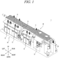
- the battery disconnect device 1 includes a power supply interruption unit 10 and a cooling module 20.
- the cooling module 20 may be coupled to the power supply interruption unit 10 to receive heat generated from the power supply interruption unit 10. Accordingly, each component of the power supply interruption unit 10 can be cooled and overheating of the power supply interruption unit 10 can be suppressed.
- the power supply interruption unit 10 is coupled to the cooling module 20 according to one embodiment of the present disclosure. Although not illustrated, it will be understood that the power supply interruption unit 10 may be coupled to any one of cooling modules 30, 40, and 50 according to respective embodiments to be described later to constitute the battery disconnect device 1.
- the power supply interruption unit 10 includes a busbar 11, a contactor 12, and a fuse 13.
- the busbar 11 is coupled and electrically connected to the contactor 12 such that an external battery and other components disposed in the vehicle are electrically connected to each other.
- the busbar 11 and the contactor 12 may be provided in plurality, and the plurality of busbars 11 and the plurality of contactors 12 may be coupled and electrically connected to each other, respectively.
- portions of the cooling module 20, 30, 40, 50 that are in contact with the plurality of busbars 11 may be formed of an electrically insulating material to suppress arbitrary electrical connection between the plurality of busbars 11.
- the fuse 13 is located adjacent to the plurality of contactors 12.
- the fuse 13 may be coupled and electrically connected to any one or more of the plurality of contactors 12. That is, the busbar 11 and the contactor 12 are each electrically connected to the battery (not illustrated) and other components of the vehicle through the fuse 13.
- the cooling module 20 is coupled to the power supply interruption unit 10 and receives heat (hereinafter, referred to as "generated heat") which has been generated from the battery (not illustrated) and transferred to the power supply interruption unit 10 or heat which has been generated from the power supply interruption unit 10.
- the received heat (generated heat) is discharged to the outside of the battery disconnect device 1 through a heat transfer medium that flows inside the cooling module 20. Accordingly, each component of the power supply interruption unit 10 and the battery (not illustrated) coupled and electrically connected to the power supply interruption unit 10 can be cooled.
- the heat transfer medium may flow inside the cooling module 20.
- the heat transfer medium may be gas or liquid.
- the heat transfer medium may be water.
- the cooling module 20 is configured to cool the power supply interruption unit 10 in a water cooling manner.
- the cooling module 20 may be coupled to the power supply interruption unit 10 in any form capable of receiving generated heat and discharging the same to the outside of the battery disconnect device 1.
- the cooling module 20 is coupled to the power supply interruption unit 10 on the top of the power supply interruption unit 10 while covering the components of the power supply interruption unit 10.
- one side facing the power supply interruption unit 10 namely, a lower portion in the illustrated embodiment may be in contact with the busbars 11.
- the lower portion of the cooling module 20 may be coupled to the busbars 11.
- the lower portion of the cooling module 20 and the busbars 11 may exchange heat by conduction. Accordingly, the generated heat can be effectively transferred from the busbars 11 to the cooling module 20.
- the cooling module 20 includes a heat dissipation part 100, a pipe part 200, and a heat transfer part 300.
- the heat dissipation part 100 is coupled to the busbars 11 and receives heat generated from the busbars 11. Additionally, the heat dissipation part 100 is coupled to the pipe part 200 and transfers the received heat to the pipe part 200 and a heat transfer medium flowing within the pipe part 200.
- the heat dissipation part 100 is coupled to the pipe part 200.
- a space (a pipe coupling portion (or pipe coupling part) 140 to be described later) may be formed inside the heat dissipation part 100, so that the pipe part 200 can be accommodated in communication with the outside.
- the heat dissipation part 100 is coupled to the heat transfer part 300.
- a space (a transfer coupling portion 150 to be described later) may be formed inside the heat dissipation part 100, so that the heat transfer part 300 can be accommodated.
- the heat dissipation part 100 may be formed in a shape corresponding to the shape of the cooling module 20.
- the heat dissipation part 100 has a rectangular pillar shape with a length in the left-to-right direction, a width in the front-to-rear direction, and a thickness in the vertical direction. It will be understood that the shape of the heat dissipation part 100 may change to correspond to the shape of the power supply interruption unit 10.
- the heat dissipation part 100 may be formed of an electrically insulating material.
- the heat dissipation part 100 is coupled to the plurality of busbars 11 and is intended to block random electrical connection between the plurality of busbars 11 coupled thereto.
- the heat dissipation part 100 may be formed of a material with high thermal conductivity. This is because the heat dissipation part 100 is coupled to the plurality of busbars 11 to receive generated heat and transfer it to the pipe part 200.
- the heat dissipation part 100 may be formed of a material having thermal conductivity of 0.5 W/mK or more.
- the heat dissipation part 100 may be formed of a material having thermal conductivity of 2.0 W/mK or more.
- thermo conductivity it is sufficient as long as thermal conductivity can be more improved than that in the case where the heat dissipation part 100 is formed of a typical synthetic resin material.
- the heat dissipation part 100 may be made by mixing a material, which can provide electrical insulating property and thermal conductivity with synthetic resin, such as polyphenylene sulfide (PPS), polycarbonate (PC), polyamide (PA), polybutylene terephthalate (PBT), liquid crystal polymer (LCP), or the like, which has excellent heat resistance.
- synthetic resin such as polyphenylene sulfide (PPS), polycarbonate (PC), polyamide (PA), polybutylene terephthalate (PBT), liquid crystal polymer (LCP), or the like, which has excellent heat resistance.
- the material may include ceramic-based fillers such as boron nitride (BN), aluminum nitride (AIN), silicon carbide (SiC), magnesium oxide (MgO), and aluminum oxide (Al2O3).
- ceramic-based fillers such as boron nitride (BN), aluminum nitride (AIN), silicon carbide (SiC), magnesium oxide (MgO), and aluminum oxide (Al2O3).
- the heat dissipation part 100 may be formed of a thermal conductive plastic or thermal conductive rubber material.
- the heat dissipation part 100, the pipe part 200, and the heat transfer part 300 may be coupled together through a single process.
- the heat dissipation part 100 is formed of a material including synthetic resin
- a material forming the heat dissipation part 100 may be molded to form the cooling module 20.
- the cooling module 20 may be manufactured by insert molding.
- the heat dissipation part 100, the pipe part 200, and the heat transfer part 300 may be coupled in close contact with one another, thereby improving airtightness and heat transfer efficiency.
- the pipe part 200 is kept coupled to the heat dissipation part 100 and the heat transfer part 300, and the heat transfer medium flows only inside the pipe part 200. Therefore, no separate configuration is required to suppress random leakage of the heat transfer medium.
- the heat dissipation part 100 includes a heat dissipation body 110, a fin member 120, a busbar coupling portion130, a pipe coupling portion 140, and a transfer coupling portion 150.
- the cooling module 20 may be manufactured by insert-molding. In the embodiment, no separate configurations are required to couple the pipe part 200 and the heat transfer part 300 to the heat dissipation part 100 and maintain the coupled state.
- components for coupling with other members that is, the busbar coupling portion 130, the pipe coupling portion 140, and the transfer coupling portion 150 are not formed separately but are manufactured together with the heat dissipation body 110 by insert-molding. This can reduce manufacturing cost and time by virtue of the reduction of the components.
- the heat dissipation body 110 defines the body of the heat dissipation part 100. A space is formed inside the heat dissipation body 110 to accommodate the busbars 11, the pipe part 200, and the heat transfer part 300.
- the heat dissipation body 110 extends in an extending direction of the heat dissipation part 100, namely, in the left-to-right direction in the illustrated embodiment.
- the extending direction of the heat dissipation body 110 may be determined to correspond to the extending direction of the pipe part 200 or the heat transfer part 300. Additionally, the extending direction of the heat dissipation body 110 may be determined to correspond to a direction in which the plurality of busbars 11 are disposed side by side to be spaced apart from one another.
- the fin member 120 is disposed on an outer periphery of the heat dissipation body 110.
- the fin member 120 is disposed on the outer periphery of the heat dissipation body 110 and is configured to increase the area of the outer peripheral surface of the heat dissipation body 110. Accordingly, heat transferred to the heat dissipation body 110 can be effectively dissipated to the outside of the heat dissipation body 110 through the fin member 120.
- the fin member 120 may be formed in any shape that can increase the area of the outer peripheral surface of the heat dissipation body 110.
- the fin member 120 is formed in a plate shape that extends in a width direction of the heat dissipation body 110, that is, in the front-to-rear direction, and protrudes upward.
- the fin member 120 may be provided in plurality.
- the plurality of fin members 120 may be spaced apart from one another and disposed side by side along the extending direction of the heat dissipation body 110.
- the plurality of fin members 120 are spaced apart from one another and form portions of the outer periphery of the heat dissipation body 110 along the left-to-right direction.
- the fin members 120 may be disposed at arbitrary positions on the outer periphery of the heat dissipation body 110.
- the fin members 120 are shown as being formed on one side opposite to the power supply interruption unit 10, namely, an upper side of the outer periphery of the heat dissipation body 110.
- the fin members 120 may also be formed on an edge of the heat dissipation body 110, namely, a front or rear edge in the illustrated embodiment.
- the busbar coupling portion 130, the pipe coupling portion 140, and the transfer coupling portion 150 are formed inside the heat dissipation body 110.
- the busbar coupling portion 130 is a space that accommodates the busbar 11.
- the busbar coupling portion 130 is formed inside the heat dissipation body 110, so that the busbar 11 accommodated in the busbar coupling portion 130 can be in contact with the heat dissipation body 110. Due to the contact, generated heat may be transferred from the busbar 11 to the heat dissipation body 110.
- the busbar coupling portion 130 is located on another side, facing the power supply interruption unit 10, of each side of the heat dissipation body 110, namely, on a lower side in the illustrated embodiment.
- the busbar coupling portion 130 is disposed to face the fin member 120 with the pipe coupling portion 140 and the transfer coupling portion 150 interposed therebetween.
- the busbar coupling portion 130 may have a shape corresponding to the shape of the busbar 11.
- the busbar 11 is formed in a rectangular plate shape, and thus the busbar coupling portion 130 may also be formed as a rectangular plate-shaped space with a rectangular cross-section and a thickness in the vertical direction.
- the busbar coupling portion 130 may be provided in plurality.
- the plurality of busbar coupling portions 130 may be spaced apart from one another and disposed side by side along the extending direction of the heat dissipation body 110. Accordingly, the plurality of busbars 11 may be respectively accommodated in the plurality of busbar coupling portions 130, to be physically and electrically spaced apart from one another.
- the plurality of busbar coupling portions 130 may be formed to correspond to the shape of the busbar 11 they each accommodate.
- some of the plurality of busbar coupling portions 130 may be formed through the heat dissipation body 110 along a width direction of the heat dissipation body 110, namely, in the front-to-rear direction in the illustrated embodiment. Some other of the plurality of busbar coupling portions 130 may be recessed in one of surfaces of the heat dissipation body 110 in the width direction, that is, in a front or rear surface in the illustrated embodiment.
- busbar 11 it is sufficient as long as the accommodated busbar 11 is stably supported and can be physically and electrically spaced apart from other busbars 11.
- the pipe coupling portion 140 and the transfer coupling portion 150 are located adjacent to the busbar coupling portion 130.
- the pipe coupling portion 140 is a space in which the pipe part 200 is accommodated.
- the pipe coupling portion 140 is formed inside the heat dissipation body 110.
- the pipe coupling portion 140 may extend in a longitudinal direction of the heat dissipation body 110, namely, in the left-to-right direction in the illustrated embodiment.
- Each end portion in the extending direction of the pipe coupling portion 140 namely, right and left end portions in the illustrated embodiment are open to communicate with the outside.
- Each end portion of the pipe part 200 may be exposed to the outside through the end portion of the pipe coupling portion 140.
- the pipe coupling portion 140 may have any shape capable of accommodating the pipe part 200.
- the pipe coupling portion 140 is formed as a cylindrical space that has a circular cross-section and extends in the left-to-right direction to correspond to the shape of the pipe part 200.
- the pipe coupling portion 140 communicates with a pipe accommodating portion 320 of the heat transfer part 300. Accordingly, a portion of the pipe part 200 is accommodated in the pipe coupling portion 140, and the remaining portion of the pipe part 200 is accommodated in the pipe accommodating portion 320. Accordingly, it can be said that the pipe coupling portion 140 partially accommodates the pipe part 200.
- the pipe coupling portion 140 is located between the busbar coupling portion 130 and the fin member 120. That is, in the illustrated embodiment, the pipe coupling portion 140 is located below the fin member 120 and above the busbar coupling portion 130.
- the transfer coupling portion 150 is a space in which the heat transfer part 300 is accommodated.
- the transfer coupling portion 150 is formed inside the heat dissipation body 110.
- the transfer coupling portion 150 extends in the longitudinal direction of the heat dissipation body 110, namely, in the left-to-right direction in the illustrated embodiment.
- Each end portion in the extending direction of the transfer coupling portion 150 namely, right and left end portions in the illustrated embodiment are open to communicate with the outside.
- a coupling protrusion (not given reference numeral) formed on each end portion of the heat transfer part 300 may be exposed to the outside through the end portion of the transfer coupling portion 150.
- the transfer coupling portion 150 communicates with the pipe coupling portion 140.
- the pipe part 200 portion of which is accommodated in the pipe accommodating portion 320 of the heat transfer part 300, may have another portion accommodated in the pipe coupling portion 140.
- the pipe part 200 may extend long along the direction in which the heat dissipation body 110 or the transfer body 310 extends. In the illustrated embodiment, the pipe part 200 extends long in the left-to-right direction. It will be understood that the extending direction of the pipe part 200 is the same as the extending direction of the profile of the power supply interruption unit 10.
- the pipe body 210 defines the body of the pipe part 200.
- the pipe body 210 may extend long in the extending direction, namely, in the left-to-right direction in the illustrated embodiment. Each end portion of the pipe body 210 in the extending direction may be exposed to the outside of the heat dissipation body 110 and communicate with the outside.
- the pipe body 210 may be formed of a material with high thermal conductivity. This is to quickly receive the generated heat and quickly transfer it to the heat transfer medium flowing in the pipe body.
- the pipe body 210 may be formed of an electrically insulating material. This is to suppress arbitrary electrical connection with the busbar 11, which is accommodated in the heat dissipation body 110 together with the pipe body 210.
- the pipe body 210 may be formed of a material with water resistance. In an embodiment in which the heat transfer medium is water, this is to suppress corrosion of the pipe body 210 by the heat transfer medium.
- the pipe body 210 may be formed of aluminum or a metal alloy material containing aluminum.
- the pipe hollow 220 is formed inside the pipe body 210.
- the pipe hollow 220 is a space through which the heat transfer medium flows.
- the pipe hollow 220 is formed through the inside of the pipe body 210 along the longitudinal direction of the pipe body 210.
- the pipe hollow 220 is formed through the pipe body 210 in the left-to-right direction which is the same as the extending direction of the pipe body 210.
- Each end portion of the pipe hollow 220 namely, right and left end portions in the illustrated embodiment are open.
- the pipe hollow 220 may communicate with the outside through the respective end portions thereof. That is, the heat transfer medium may flow into the pipe hollow 220 through any one of the end portions, and may flow out of the pipe hollow 220 through the other end portion.
- the pipe hollow 220 may have any shape which is open to communicate with the outside and in which the heat transfer medium can flow.
- the pipe hollow 220 has a circular cross-section and extends in the direction in which the pipe body 210 extends, namely, in the left-to-right direction in the illustrated embodiment.
- the cooling module 20 includes the heat transfer part 300.
- the heat transfer part 300 receives heat generated from the battery (not illustrated) or the busbar 11 and transfers the received heat to the pipe part 200 or the heat dissipation part 100. In other words, it can be said that the busbar 11 exchanges heat with the pipe part 200 or the heat dissipation part 100 via the heat transfer part 300.
- the heat transfer part 300 is accommodated in the transfer coupling portion 150 and is coupled to the heat dissipation part 100.
- the heat transfer part 300 accommodated in the transfer coupling portion 150 may be in contact with an inner periphery of the heat dissipation body 110.
- the heat transfer part 300 accommodated in the transfer coupling portion 150 may be surrounded by the inner periphery of the heat dissipation body 110.
- the heat transfer part 300 is coupled to the pipe part 200. Specifically, the inner periphery of the heat transfer part 300 may be in contact with the pipe part 200 accommodated in the pipe accommodating portion 320. Accordingly, the heat transferred to the heat transfer part 300 may be transferred to the pipe part 200 and the heat transfer medium flowing within the pipe part 200.
- heat generated from the busbar 11 can be discharged to the outside through various paths. That is, part of the generated heat may be discharged to the outside through the heat dissipation body 110 and the fin member 120. Another part of the generated heat may be transferred to the heat transfer part 300 through the heat dissipation body 110. The heat transferred to the heat transfer part 300 may partially be transferred to the pipe part 200 and partially to the fin member 120.
- heat generated from the battery (not illustrated) or the busbar 11 can be dissipated simultaneously through various paths, thereby improving the cooling efficiency of the battery disconnect device 1.
- the heat transfer part 300 may be formed of a material with high thermal conductivity. This is to quickly receive and transfer generated heat.
- the heat transfer part 300 may be formed of an electrically insulating material. This is to suppress arbitrary electrical connection to the plurality of busbars 11 disposed adjacently.
- the heat transfer part 300 may be formed of aluminum or a metal alloy material containing aluminum.
- the heat transfer part 300 includes a transfer body 310 and a pipe accommodating portion 320.
- the transfer body 310 defines the body of the heat transfer part 300.
- the heat transfer part 310 may be accommodated in the transfer coupling portion 150 and disposed so that its outer peripheral surface is in contact with the inner peripheral surface of the heat dissipation body 110. Accordingly, heat transfer may be made by conduction between the transfer body 310 and the heat dissipation body 110.
- the transfer body 310 may be formed in a shape corresponding to the shape of the heat dissipation body 110 or the transfer coupling portion 150 formed therein.
- the transfer body 310 is formed to have an extension length in the left-to-right direction longer than an extension length in the front-to-rear direction, and has a thickness in the vertical direction.
- the heat transfer medium flows only in the pipe hollow 220. That is, until the heat transfer medium flows in from the outside of the cooling module 20 and then flows out after heat exchange, the heat transfer medium does not leak or flow to the outside of the pipe part 200.
- the heat dissipation part 100, the pipe part 200, and the heat transfer part 300 may be coupled in close contact by insert-molding. Accordingly, separate members and processes for coupling the heat dissipation part 100, the pipe part 200, and the heat transfer part 300 are not required, which can reduce manufacturing costs and simplify the manufacturing process.
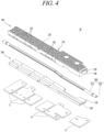
- the cooling module 30 includes a heat dissipation part 100 and a pipe part 200.
- the heat dissipation part 100 is coupled to the busbar 11 and receives heat generated from the busbar 11. Additionally, the heat dissipation part 100 is coupled to the pipe part 200 and transfers the received heat to the pipe part 200 and a heat transfer medium flowing within the pipe part 200.
- the heat dissipation part 100 may be formed in a shape corresponding to the shape of the cooling module 30.
- the heat dissipation part 100 has a rectangular pillar shape with a length in the left-to-right direction, a width in the front-to-rear direction, and a thickness in the vertical direction. It will be understood that the shape of the heat dissipation part 100 may change to correspond to the shape of the power supply interruption unit 10.
- the conditions and properties of the material forming the heat dissipation part 100 according to this embodiment are the same as those of the heat dissipation part 100 disposed in the cooling module 20 according to the previous embodiment. Accordingly, the description of the material of the heat dissipation part 100 will be replaced with the foregoing description.
- any separate component is not required to couple each component of the cooling module 30, that is, the heat dissipation part 100 and the pipe part 200, and maintain the coupled state. This can reduce manufacturing cost and time by virtue of the reduction of the number of components.
- the heat dissipation part 100 and the pipe part 200 may be coupled in close contact with each other, thereby improving airtightness and heat transfer efficiency.
- the pipe part 200 is maintained coupled to the heat dissipation part 100, and the heat transfer medium flows only inside the pipe part 200. Therefore, no separate configuration is required to suppress random leakage of the heat transfer medium.
- cooling module 30 can be disposed in a small battery disconnect device 1, compared to the cooling module 20 according to the previous embodiment.
- the heat dissipation part 100 may include a heat dissipation body 110, a fin member 120, a busbar coupling portion 130, and a pipe coupling portion 140.
- the cooling module 30 may be manufactured by insert-molding. In the embodiment, any separate component is not required to couple the pipe part 200 to the heat dissipation part 100 and maintain the coupled state.
- components that is, the busbar coupling portion 130 and the pipe coupling portion 140 for coupling with other members are not formed separately but are manufactured together with the heat dissipation body 110 by insert-molding. This can reduce manufacturing cost and time by virtue of the reduction of the number of components.
- the illustrated embodiment is in a disassembled state for explanation of the structure, under assumption that the manufacturing of the heat dissipation part 100 by insert-molding and the coupling of the heat dissipation part 100 with the pipe part 200 have been completed.
- the heat dissipation body 110 defines the body of the heat dissipation part 100. A space is formed inside the heat dissipation body 110 to accommodate the busbar 11 and the pipe part 200.
- the heat dissipation body 110 extends in an extending direction of the heat dissipation part 100, namely, in the left-to-right direction in the illustrated embodiment.
- the extending direction of the heat dissipation body 110 may be determined to correspond to the extending direction of the pipe part 200. Additionally, the extending direction of the heat dissipation body 110 may be determined to correspond to a direction in which the plurality of busbars 11 are disposed side by side to be spaced apart from one another.
- the fin member 120 is disposed on an outer periphery of the heat dissipation body 110.
- the fin member 120 is disposed on the outer periphery of the heat dissipation body 110 and is configured to increase the area of the outer peripheral surface of the heat dissipation body 110. Accordingly, heat transferred to the heat dissipation body 110 can be effectively dissipated to the outside of the heat dissipation body 110 through the fin member 120.
- the fin member 120 may be formed in any shape that can increase the area of the outer peripheral surface of the heat dissipation body 110.
- the fin member 120 is formed in a plate shape that extends in a width direction of the heat dissipation body 110, that is, in the front-to-rear direction, and protrudes upward.
- the fin member 120 may be provided in plurality.
- the plurality of fin members 120 may be spaced apart from one another and disposed side by side along the extending direction of the heat dissipation body 110.
- the plurality of fin members 120 are spaced apart from one another and form a portion of the outer periphery of the heat dissipation body 110 along the left-to-right direction.
- the fin members 120 may be disposed at arbitrary positions on the outer periphery of the heat dissipation body 110.
- the fin members 120 are shown as being formed on one side opposite to the power supply interruption unit 10, namely, an upper side of the outer periphery of the heat dissipation body 110.
- the fin members 120 may also be formed on an edge of the heat dissipation body 110, namely, on a front or rear edge in the illustrated embodiment.
- the busbar coupling portion 130 and the pipe coupling portion 140 are formed inside the heat dissipation body 110.
- the busbar coupling portion 130 is a space that accommodates the busbar 11.
- the busbar coupling portion 130 is formed inside the heat dissipation body 110, so that the busbar 11 accommodated in the busbar coupling portion 130 can be in contact with the heat dissipation body 110. Due to the contact, generated heat can be transferred from the busbar 11 to the heat dissipation body 110.
- the busbar coupling portion 130 is located on another side, facing the power supply interruption unit 10, of each side of the heat dissipation body 110, namely, on a lower side in the illustrated embodiment.
- the busbar coupling portion 130 is disposed to face the fin member 120 with the pipe coupling portion 140 interposed therebetween.
- the busbar coupling portion 130 may have a length corresponding to the shape of the busbar 11.
- the busbar 11 is formed in a rectangular plate shape, and thus the busbar coupling portion 130 may also be formed as a rectangular plate-shaped space with a rectangular cross-section and a thickness in the vertical direction.
- the busbar coupling portion 130 may be provided in plurality.
- the plurality of busbar coupling portions 130 may be spaced apart from one another and disposed side by side along the extending direction of the heat dissipation body 110. Accordingly, the plurality of busbars 11 may be respectively accommodated in the plurality of busbar coupling portions 130, to be physically and electrically spaced apart from one another.
- the plurality of busbar coupling portions 130 may be formed to correspond to the shape of the busbars 11 accommodated therein.
- some of the plurality of busbar coupling portions 130 may be formed through the heat dissipation body 110 along a width direction of the heat dissipation body 110, namely, in the front-to-rear direction in the illustrated embodiment. Some other of the plurality of busbar coupling portions 130 may be recessed in one of surfaces of the heat dissipation body 110 in the width direction, that is, in a front or rear surface in the illustrated embodiment.
- the accommodated busbar 11 is stably supported and can be physically and electrically spaced apart from other busbars 11.
- the pipe coupling portion 140 is located adjacent to the busbar coupling portion 130.
- the pipe coupling portion 140 is a space that accommodates the pipe part 200.
- the pipe coupling portion 140 is formed inside the heat dissipation body 110.
- the pipe coupling portion 140 may extend in a longitudinal direction of the heat dissipation body 110, namely, in the left-to-right direction in the illustrated embodiment.
- Each end portion of the pipe coupling portion 140 namely, right and left end portions in the illustrated embodiment are open to communicate with the outside.
- Each end portion of the pipe part 200 may be exposed to the outside through the end portion of the pipe coupling portion 140.
- the pipe coupling portion 140 may have any shape capable of accommodating the pipe part 200.
- the pipe coupling portion 140 is formed as a cylindrical space that has a circular cross-section and extends in the left-to-right direction to correspond to the shape of the pipe part 200.
- the pipe coupling portion 140 is located between the busbar coupling portion 130 and the fin member 120. That is, in the illustrated embodiment, the pipe coupling portion 140 is located below the fin member 120 and above the busbar coupling portion 130.
- the cooling module 30 includes the pipe part 200.
- the pipe part 200 forms a passage through which a heat transfer medium flows, and here, the heat transfer medium receives heat generated from the battery (not illustrated) or the power supply interruption unit 10 and discharges the received heat to the outside.
- the inside of the pipe part 200 communicates with the outside of the battery disconnect device 1, but is blocked from communication with the inside of the battery disconnect device 1.
- the pipe part 200 is coupled to the heat dissipation part 100. Specifically, the pipe part 200 is accommodated in the pipe coupling portion 140 of the heat dissipation part 100. The outer periphery of the pipe part 200 accommodated in the pipe coupling portion 140 may be in contact with the inner periphery of the heat dissipation body 110 which surrounds the pipe coupling portion 140.
- the heat generated from the busbar 11 can be transferred to the pipe part 200 through the heat dissipation body 110.
- the transferred heat may be discharged to the outside of the battery disconnect device 1 through the heat transfer medium flowing inside the pipe part 200.
- the pipe part 200 may extend long along the direction in which the heat dissipation body 110 extends. In the illustrated embodiment, the pipe part 200 extends long in the left-to-right direction. It will be understood that the extending direction of the pipe part 200 is the same as the extending direction of the profile of the power supply interruption unit 10.
- the pipe part 200 includes a pipe body 210 and a pipe hollow 220.
- the pipe body 210 defines the body of the pipe part 200.
- the pipe body 210 may extend long in the extending direction, namely, in the left-to-right direction in the illustrated embodiment. Each end portion of the pipe body 210 in the extending direction may be exposed to the outside of the heat dissipation body 110 and communicate with the outside.
- the pipe body 210 may be formed in any shape capable of forming a passage of the heat transfer medium through the pipe hollow 220 formed therein.
- the pipe body 210 may be formed in a cylindrical shape that has a circular cross-section and extends in the left-to-right direction.
- the pipe body 210 may be formed of a material with high thermal conductivity. This is to quickly receive the generated heat and quickly transfer it to the heat transfer medium flowing in the pipe body.
- the pipe body 210 may be formed of an electrically insulating material. This is to suppress arbitrary electrical connection with the busbar 11, which is accommodated in the heat dissipation body 110 together with the pipe body 210.
- the pipe body 210 may be formed of a material with water resistance. In an embodiment in which the heat transfer medium is water, this is to suppress corrosion due to the heat transfer medium.
- the pipe body 210 may be formed of aluminum or a metal alloy material containing aluminum.
- the pipe hollow 220 is formed inside the pipe body 210.
- the pipe hollow 220 is a space through which the heat transfer medium flows.
- the pipe hollow 220 is formed through the inside of the pipe body 210 along the longitudinal direction of the pipe body 210.
- the pipe hollow 220 is formed through the pipe body 210 in the left-to-right direction which is the same as the extending direction of the pipe body 210.
- Respective end portions of the pipe hollow 220 are open.
- the pipe hollow 220 may communicate with the outside through the respective end portions. That is, the heat transfer medium may flow into the pipe hollow 220 through any one of the end portions, and may flow out of the pipe hollow 220 through the other end portion.
- the pipe hollow 220 may have any shape which is open to communicate with the outside such that the heat transfer medium can flow.
- the pipe hollow 220 has a circular cross-section and extends in the direction in which the pipe body 210 extends, namely, in the left-to-right direction in the illustrated embodiment.
- the cooling module 30 can dissipate heat generated from the battery (not illustrated) or the busbar 11 to the outside through various paths.
- the busbar 11 may be accommodated in the busbar coupling portion 130 of the heat dissipation part 100, and the generated heat may be transferred to the heat dissipation body 110.
- the plurality of fin members 120 are formed on the outer periphery of the heat dissipation body 110 on one side thereof, namely, on an upper outer periphery in the illustrated embodiment. A part of the heat transferred to the portion of the heat dissipation body 110, that is, the portion surrounding the busbar coupling portion 130 may be dissipated to the outside through the plurality of fin members 120.
- the pipe part 200 is accommodated in the pipe coupling portion 140 formed inside the heat dissipation body 110.
- the pipe part 200 is disposed so that its outer periphery is in contact with the inner periphery of the heat dissipation body 110.
- a part of the heat transferred to the pipe part 200 may be dissipated to the outside through the heat transfer medium, or may be dissipated to the outside through the fin members 120 via the heat dissipation body 110 again.
- the heat transfer medium flows only in the pipe hollow 220. That is, until the heat transfer medium flows in from the outside of the cooling module 30 and then flows out after heat exchange, the heat transfer medium does not leak or flow to the outside of the pipe part 200.
- the heat dissipation part 100 and the pipe part 200 may be coupled in close contact by insert-molding. Accordingly, separate members and processes for coupling the heat dissipation part 100 and the pipe part 200 are not required, which can reduce manufacturing costs and simplify the manufacturing process.
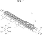
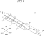
- a cooling module 40 according to still another embodiment of the present disclosure is illustrated.
- the cooling module 40 according to this embodiment has the same functions but has some differences in configuration. Therefore, in the following description, the cooling module 40 according to this embodiment will be described in detail, focusing on the configuration.
- one side namely, a lower side facing the power supply interruption unit 10, of each side of the cooling module 40, may be in contact with the busbar 11 to exchange heat.
- the cooling module 40 according to this embodiment is not provided with a component corresponding to the heat transfer part 300. Accordingly, it will be understood that a discharge path related to the heat transfer part 300 among the discharge paths of the heat generated from the battery (not illustrated) or the busbar 11 is not formed.
- the cooling module 40 has a difference in the shape of the pipe part 200.
- the pipe part 200 may be formed to be partially flat. Accordingly, a contact area between the pipe part 200 and the heat dissipation portion 100 can increase, thereby improving heat exchange efficiency.
- the cooling module 40 includes a heat dissipation part 100 and a pipe part 200.
- the heat dissipation part 100 is coupled to the busbar 11 and receives heat generated from the busbar 11. Additionally, the heat dissipation part 100 is coupled to the pipe part 200 and transfers the received heat to the pipe part 200 and a heat transfer medium flowing within the pipe part 200.
- the heat dissipation part 100 is coupled to the pipe part 200.
- a space (a pipe coupling portion 140 to be described later) may be formed inside the heat dissipation part 100, so that the pipe part 200 can be accommodated in communication with the outside.
- the heat dissipation part 100 may be formed in a shape corresponding to the shape of the cooling module 40.
- the heat dissipation part 100 has a rectangular pillar shape with a length in the left-to-right direction, a width in the front-to-rear direction, and a thickness in the vertical direction. It will be understood that the shape of the heat dissipation part 100 may change to correspond to the shape of the power supply interruption unit 10.
- the conditions and properties of the material forming the heat dissipation part 100 according to this embodiment are the same as those of the heat dissipation part 100 disposed in the cooling modules 20 and 30 according to the previous embodiments. Accordingly, the description of the material of the heat dissipation part 100 will be replaced with the foregoing description.
- the heat dissipation part 100 and the pipe part 200 may be coupled to each other through a single process.
- the heat dissipation part 100 is formed of a material containing synthetic resin
- a material forming the heat dissipation part 100 may be insert-molded to form the cooling module 40.
- the cooling module 40 may be manufactured by insert-molding.
- any separate component is not required to couple each component of the cooling module 40, that is, the heat dissipation part 100 and the pipe part 200, and maintain the coupled state. This can reduce manufacturing cost and time by virtue of the reduction of the number of components.
- the heat dissipation part 100 and the pipe part 200 may be coupled in close contact with each other, thereby improving airtightness and heat transfer efficiency.
- the size of the heat dissipation part 100 can be reduced.
- the pipe part 200 is maintained coupled to the heat dissipation part 100, and the heat transfer medium flows only inside the pipe part 200. Therefore, no separate configuration is required to suppress arbitrary leakage of the heat transfer medium.
- cooling module 40 can be disposed in a small battery disconnect device 1, compared to the cooling module 20 according to the previous embodiment.
- the heat dissipation part 100 may include a heat dissipation body 110, a fin member 120, a busbar coupling portion 130, and a pipe coupling portion 140.
- the cooling module 40 may be manufactured by insert-molding. In the embodiment, any separate component is not required to couple the pipe part 200 to the heat dissipation part 100 and maintain the coupled state.
- components that is, the busbar coupling portion 130 and the pipe coupling portion 140 for coupling with other members are not formed separately but are manufactured together with the heat dissipation body 110 by insert-molding. This can reduce manufacturing cost and time by virtue of the reduction of the number of components.
- the illustrated embodiment is in a disassembled state for explanation of the structure, under assumption that the manufacturing of the heat dissipation part 100 by insert-molding and the coupling of the heat dissipation part 100 with the pipe part 200 have been completed.
- the heat dissipation body 110 defines the body of the heat dissipation part 100. A space is formed inside the heat dissipation body 110 to accommodate the busbar 11 and the pipe part 200.
- the heat dissipation body 110 extends in an extending direction of the heat dissipation part 100, namely, in the left -to-right direction in the illustrated embodiment.
- the extending direction of the heat dissipation body 110 may be determined to correspond to the extending direction of the pipe part 200. Additionally, the extending direction of the heat dissipation body 110 may be determined to correspond to a direction in which the plurality of busbars 11 are disposed side by side to be spaced apart from one another.
- the fin member 120 is disposed on an outer periphery of the heat dissipation body 110.
- the fin member 120 is disposed on the outer periphery of the heat dissipation body 110 and is configured to increase the area of the outer peripheral surface of the heat dissipation body 110. Accordingly, heat transferred to the heat dissipation body 110 can be effectively dissipated to the outside of the heat dissipation body 110 through the fin member 120.
- the fin member 120 may be formed in any shape that can increase the area of the outer peripheral surface of the heat dissipation body 110.
- the fin member 120 is formed in a plate shape that extends in a width direction of the heat dissipation body 110, that is, in the front-to-rear direction, and protrudes upward.
- the fin member 120 may be provided in plurality.
- the plurality of fin members 120 may be spaced apart from one another and disposed side by side along the extending direction of the heat dissipation body 110.
- the plurality of fin members 120 are spaced apart from one another and form a portion of the outer periphery of the heat dissipation body 110 along the left-to-right direction.
- the fin members 120 may be disposed at arbitrary positions on the outer periphery of the heat dissipation body 110.
- the fin members 120 are shown as being formed on one side opposite to the power supply interruption unit 10, namely, an upper side of the outer periphery of the heat dissipation body 110.
- the fin members 120 may also be formed on an edge of the heat dissipation body 110, namely, on a front or rear edge in the illustrated embodiment.
- the busbar coupling portion 130 and the pipe coupling portion 140 are formed inside the heat dissipation body 110.
- the busbar coupling portion 130 is a space that accommodates the busbar 11.
- the busbar coupling portion 130 is formed inside the heat dissipation body 110, so that the busbar 11 accommodated in the busbar coupling portion 130 can be in contact with the heat dissipation body 110. Due to the contact, generated heat may be transferred from the busbar 11 to the heat dissipation body 110.
- the busbar coupling portion 130 is located on another side, facing the power supply interruption unit 10, of each side of the heat dissipation body 110, namely, on a lower side in the illustrated embodiment.
- the busbar coupling portion 130 is disposed to face the fin member 120 with the pipe coupling portion 140 interposed therebetween.
- the busbar coupling portion 130 may have a length corresponding to the shape of the busbar 11.
- the busbar 11 is formed in a rectangular plate shape, and thus the busbar coupling portion 130 may also be formed as a rectangular plate-shaped space with a rectangular cross-section and a thickness in the vertical direction.
- the busbar coupling portion 130 may be provided in plurality.
- the plurality of busbar coupling portions 130 may be spaced apart from one another and disposed side by side along the extending direction of the heat dissipation body 110. Accordingly, the plurality of busbars 11 may be respectively accommodated in the plurality of busbar coupling portions 130, to be physically and electrically spaced apart from one another.
- the plurality of busbar coupling portions 130 may be formed to correspond to the shape of the busbars 11 accommodated therein.
- some of the plurality of busbar coupling portions 130 may be formed through the heat dissipation body 110 along a width direction of the heat dissipation body 110, namely, in the front-to-rear direction in the illustrated embodiment. Some other of the plurality of busbar coupling portions 130 may be recessed in one of surfaces of the heat dissipation body 110 in the width direction, that is, in a front or rear surface in the illustrated embodiment.
- the pipe coupling portion 140 may have any shape capable of accommodating the pipe part 200. As described above, the pipe part 200 disposed in the cooling module 40 according to this embodiment is formed such that a portion of the pipe body 210 is flat.
- the pipe part 200 is coupled to the heat dissipation part 100. Specifically, the pipe part 200 is accommodated in the pipe coupling portion 140 of the heat dissipation part 100. The outer periphery of the pipe part 200 accommodated in the pipe coupling portion 140 may be in contact with the inner periphery of the heat dissipation body 110 which surrounds the pipe coupling portion 140.
- the pipe body 210 may be formed in any shape capable of forming a passage of the heat transfer medium through the pipe hollow 220 formed therein.
- the pipe body 210 extends in the left-to-right direction, such that each end portion in the extending direction has a circular cross-section, and a portion between the end portions has a rectangular cross-section with a width in the front-to-rear direction and a thickness in the vertical direction.
- the pipe body 210 may be formed of a material with water resistance. In an embodiment in which the heat transfer medium is water, this is to suppress corrosion by the heat transfer medium.
- the pipe body 210 may be formed of aluminum or a metal alloy material containing aluminum.
- the pipe hollow 220 is formed inside the pipe body 210.
- the pipe hollow 220 is a space through which the heat transfer medium flows.
- the pipe hollow 220 is formed through the inside of the pipe body 210 along the longitudinal direction of the pipe body 210.
- the pipe hollow 220 is formed through the pipe body 210 in the left-to-right direction which is the same as the extending direction of the pipe body 210.
- Respective end portions of the pipe hollow 220 are open.
- the pipe hollow 220 may communicate with the outside through the respective end portions. That is, the heat transfer medium may flow into the pipe hollow 220 through any one of the end portions, and may flow out of the pipe hollow 220 through the other end portion.
- the busbar 11 may be accommodated in the busbar coupling portion 130 of the heat dissipation part 100, and the generated heat may be transferred to the heat dissipation body 110.
- the plurality of fin members 120 are formed on the outer periphery of the heat dissipation body 110 on one side thereof, namely, on an upper outer periphery in the illustrated embodiment. A part of the heat transferred to the portion of the heat dissipation body 110, that is, the portion surrounding the busbar coupling portion 130 may be dissipated to the outside through the plurality of fin members 120.
- the pipe part 200 is accommodated in the pipe coupling portion 140 formed inside the heat dissipation body 110.
- the pipe part 200 is disposed so that its outer periphery is in contact with the inner periphery of the heat dissipation body 110.
- another part of the heat transferred to the portion of the heat dissipation body 110 can be transferred to the pipe part 200.
- a part of the heat transferred to the pipe part 200 may be dissipated to the outside through the heat transfer medium or may be dissipated to the outside through the fin member 120 via the heat dissipation body 110 again.
- the heat transfer medium flows only in the pipe hollow 220. That is, until the heat transfer medium flows in from the outside of the cooling module 40 and then flows out after heat exchange, the heat transfer medium does not leak or flow to the outside of the pipe part 200.
- the heat dissipation part 100 and the pipe part 200 may be coupled in close contact by insert-molding. Accordingly, separate members and processes for coupling the heat dissipation part 100 and the pipe part 200 are not required, which can reduce manufacturing costs and simplify the manufacturing process.
- the portion where the pipe part 200 is accommodated in the pipe coupling portion 140 is formed in a plate shape, so that the contact area between the pipe body 210 and the heat dissipation body 110 can increase. Accordingly, heat transfer efficiency between the pipe part 200 and the heat dissipation body 110 can be improved.
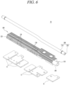
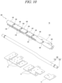
- a cooling module 50 according to still another embodiment of the present disclosure is illustrated.
- the cooling module 50 according to this embodiment has the same functions but has some differences in configuration. Therefore, in the following description, the cooling module 50 according to this embodiment will be described in detail, focusing on the configuration.
- the cooling module 50 may also constitute the battery disconnect device 10 by being coupled to the power supply interruption unit 10, in the same form as the cooling modules 20, 30 and 40 according to the previous embodiments. That is, as illustrated in FIG. 1 , the cooling module 50 may be coupled to the power supply interruption unit 10 while covering the power supply interruption unit 10 from the upper side.
- one side, namely, a lower side facing the power supply interruption unit 10, of each side of the cooling module 50, may be in contact with the busbar 11 to exchange heat.
- the cooling module 50 according to this embodiment is not provided with a component corresponding to the heat transfer part 300. Accordingly, it will be understood that a discharge path related to the heat transfer part 300 among the discharge paths of the heat generated from the battery (not illustrated) or the busbar 11 is not formed.
- the cooling module 50 does not have the fin member 120 on the heat dissipation part 100.
- the shape of the pipe coupling portion 140 disposed on the heat dissipation part 100 is configured differently.
- the cooling module 50 includes a heat dissipation part 100 and a pipe part 200.
- the heat dissipation part 100 is coupled to the busbar 11 and receives heat generated from the busbar 11. Additionally, the heat dissipation part 100 is coupled to the pipe part 200 and transfers the received heat to the pipe part 200 and a heat transfer medium flowing within the pipe part 200.
- the heat dissipation part 100 is coupled to the pipe part 200.
- the pipe coupling portion 140 to be described later may be formed outside the heat dissipation part 100, so that the pipe part 200 can be accommodated in communication with the outside.
- the heat dissipation part 100 may be formed in a shape corresponding to the shape of the cooling module 50.
- the heat dissipation part 100 has a rectangular pillar shape with a length in the left-to-right direction, a width in the front-to-rear direction, and a thickness in the vertical direction. It will be understood that the shape of the heat dissipation part 100 may change to correspond to the shape of the power supply interruption unit 10.
- the conditions and properties of the material forming the heat dissipation part 100 according to this embodiment are the same as those of the heat dissipation part 100 disposed in the cooling modules 20, 30 and 40 according to the previous embodiments. Accordingly, the description of the material of the heat dissipation part 100 will be replaced with the foregoing description.
- the heat dissipation part 100 and the pipe part 200 may be coupled to each other through a single process.
- the heat dissipation part 100 is formed of a material containing synthetic resin
- a material forming the heat dissipation part 100 may be insert-molded to form the cooling module 50.
- the cooling module 50 may be manufactured by insert-molding.
- any separate component is not required to couple each component, that is, the heat dissipation part 100 and the pipe part 200 of the cooling module 50, and maintain the coupled state. This can reduce manufacturing cost and time by virtue of the reduction of the number of components.
- the heat dissipation part 100 and the pipe part 200 may be coupled in close contact with one another, thereby improving airtightness and heat transfer efficiency.
- the size of the heat dissipation part 100 can be reduced.
- the pipe part 200 is maintained coupled to the heat dissipation part 100, and the heat transfer medium flows only inside the pipe part 200. Therefore, no separate configuration is required to suppress arbitrary leakage of the heat transfer medium.
- cooling module 50 can be disposed in a small battery disconnect device 1, compared to the cooling module 20 according to the previous embodiment.
- the heat dissipation part 100 includes a heat dissipation body 110, a busbar coupling portion 130, a pipe coupling portion 140, and a heat dissipation opening 160.
- the cooling module 50 may be manufactured by insert-molding. In the embodiment, any separate component is not required to couple the pipe part 200 to the heat dissipation part 100 and maintain the coupled state.
- components that is, the busbar coupling portion 130, the pipe coupling portion 140, and the heat dissipation opening 160 for coupling with other members are not formed separately but are manufactured together with the heat dissipation body 110 by insert-molding. This can reduce manufacturing cost and time by virtue of the reduction of the number of components.
- the illustrated embodiment is in a disassembled state for explanation of the structure, under assumption that the manufacturing of the heat dissipation part 100 by insert-molding and the coupling of the heat dissipation part 100 with the pipe part 200 have been completed.
- the heat dissipation body 110 defines the body of the heat dissipation part 100. A space is formed inside the heat dissipation body 110 to accommodate the busbar 11 and the pipe part 200.
- the heat dissipation body 110 extends in an extending direction of the heat dissipation part 100, namely, in the left -to-right direction in the illustrated embodiment.
- the extending direction of the heat dissipation body 110 may be determined to correspond to the extending direction of the pipe part 200. Additionally, the extending direction of the heat dissipation body 110 may be determined to correspond to a direction in which the plurality of busbars 11 are disposed side by side to be spaced apart from one another.
- the busbar coupling portion 130 is disposed inside the heat dissipation body 110.
- the busbar coupling portion 130 is a space in which the busbar 11 is accommodated.
- the busbar coupling portion 130 is formed inside the heat dissipation body 110, so that the busbar 11 accommodated in the busbar coupling portion 130 can be in contact with the heat dissipation body 110. Due to the contact, generated heat may be transferred from the busbar 11 to the heat dissipation body 110.
- the busbar coupling portion 130 is located on another side, facing the power supply interruption unit 10, of each side of the heat dissipation body 110, namely, on a lower side in the illustrated embodiment.
- the busbar coupling portion 130 is located opposite to the pipe coupling portion 140.
- the busbar coupling portion 130 may have a length corresponding to the shape of the busbar 11.
- the busbar 11 is formed in a rectangular plate shape, and thus the busbar coupling portion 130 may also be formed as a rectangular plate-shaped space with a rectangular cross-section and a thickness in the vertical direction.
- the busbar coupling portion 130 may be provided in plurality.
- the plurality of busbar coupling portions 130 may be spaced apart from one another and disposed side by side along the extending direction of the heat dissipation body 110. Accordingly, the plurality of busbars 11 may be respectively accommodated in the plurality of busbar coupling portions 130, to be physically and electrically spaced apart from one another.
- the plurality of busbar coupling portions 130 may be formed to correspond to the shape of the busbars 11 accommodated therein.
- some of the plurality of busbar coupling portions 130 may be formed through the heat dissipation body 110 along a width direction of the heat dissipation body 110, namely, in the front-to-rear direction in the illustrated embodiment. Some other of the plurality of busbar coupling portions 130 may be recessed in one of surfaces of the heat dissipation body 110 in the width direction, that is, in the front or rear surface in the illustrated embodiment.
- the accommodated busbar 11 is stably supported and can be physically and electrically spaced apart from other busbars 11.
- the pipe coupling portion 140 is located on one side, which is opposite to the busbar coupling portion 130 among sides of the heat dissipation body 110, namely, on an upper side in the illustrated embodiment.
- the pipe coupling portion 140 accommodates the pipe part 200.
- the pipe coupling portion 140 is formed outside the heat dissipation body 110.
- the pipe coupling portion 140 is located on one side, namely, upper side opposite to the busbar coupling portion 130.
- the pipe coupling portion 140 may extend in a longitudinal direction of the heat dissipation body 110, namely, in the left-to-right direction in the illustrated embodiment. At this time, an extension length of the pipe coupling portion 140 may be shorter than an extension length of the heat dissipation body 110 or the pipe part 200.
- the pipe coupling portion 140 may be formed to partially surround the accommodated pipe part 200.
- the pipe coupling portion 140 may be formed to partially surround a portion, which is not surrounded by the heat dissipation body 110, of each side of the pipe part 200, namely, partially surround upper, front, and rear sides in the illustrated embodiment.
- the pipe coupling portion 140 may have any shape capable of accommodating the pipe part 200. As described above, the pipe part 200 disposed in the cooling module 50 according to this embodiment is formed such that a portion of the pipe body 210 is flat.
- the pipe coupling portion 140 extends in the left-to-right direction to correspond to the shape of the pipe part 200, and each end portion of the pipe coupling portion 140 has a circular cross-section and a portion between the end portions of the pipe coupling portion 140 has a plate-shaped cross section.
- a contact area between the inner periphery of the heat dissipation body 110 surrounding the pipe coupling portion 140 and the pipe body 210 can increase, thereby improving heat exchange efficiency.
- the pipe coupling portion 140 may be provided in plurality.
- the plurality of pipe coupling portions 140 may be spaced apart from one another and disposed side by side along the extending direction of the heat dissipation body 110 or the pipe part 200.
- the plurality of pipe coupling portions 140 may be configured to surround different portions, respectively, along the extending direction of the pipe part 200.
- a distance between a pair of pipe coupling portions 140, which are located on end portions in a disposition direction thereof, may be shorter than an extension length of the pipe part 200. Accordingly, each end portion in the extending direction of the pipe part 200 may be exposed to the outside of the pipe coupling portion 140 and communicate with the outside.
- a space formed by the plurality of pipe coupling portions 140 spaced apart from each other may be defined as the heat dissipation opening 160.
- the heat dissipation opening 160 is an open space in which the pipe part 200 coupled to and accommodated in the pipe coupling portion 140 is exposed to the outside. Heat transferred to the pipe part 200 may be discharged to the outside through the heat dissipation opening 160.
- the heat dissipation opening 160 is defined by a pair of pipe coupling portions 140, which are located adjacent to each other at a spacing therebetween, among the plurality of pipe coupling portions 140.
- the pair of pipe coupling portions 140 adjacent to each other are disposed to face each other with the heat dissipation opening 160 interposed therebetween.
- the heat dissipation opening 160 may be defined in plurality. As described above, the plurality of pipe coupling portions 140 are disposed to be spaced apart from one another along the extending direction of the pipe part 200. Accordingly, the plurality of heat dissipation openings 160 may also be disposed to be spaced apart from one another along the extending direction of the pipe part 200.
- the heat dissipation opening 160 may alternatively be formed by penetrating one surface of the pipe coupling portion 140, namely, an upper surface in the illustrated embodiment. That is, as illustrated in FIGS. 9 and 10 , the heat dissipation opening 160 may be formed through the inside of the one surface of the pipe coupling portion 140 in the thickness direction.
- a path through which heat transferred to the pipe part 200 is dissipated to the outside can increase, so heat dissipation efficiency can be improved.
- a sufficient path through which the transferred heat is dissipated can be secured.
- the cooling module 50 includes the pipe part 200.
- the pipe part 200 forms a passage through which a heat transfer medium flows, and here, the heat transfer medium receives heat generated from the battery (not illustrated) or the power supply interruption unit 10 and dissipates the received heat to the outside.
- the inside of the pipe part 200 communicates with the outside of the battery disconnect device 1, but is blocked from communication with the inside of the battery disconnect device 1.
- the pipe part 200 is coupled to the heat dissipation part 100. Specifically, the pipe part 200 is accommodated in a space formed between the heat dissipation body 110 and the pipe coupling portion 140 of the heat dissipation part 100. The outer periphery of the pipe part 200 accommodated in the pipe coupling portion 140 may be in contact with the inner periphery of the heat dissipation body 110 and the pipe coupling portion 140 surrounding the space.
- the heat generated from the busbar 11 can be transferred to the pipe part 200 through the heat dissipation body 110.
- the transferred heat may be dissipated to the outside of the battery disconnect device 1 through the heat transfer medium flowing inside the pipe part 200.
- the plurality of pipe coupling portions 140 are disposed to be spaced apart from one another along the extending direction of the pipe part 200.
- the space formed between the adjacent pipe coupling portions 140 is defined as the heat dissipation opening 160.
- the heat dissipation opening 160 may also be formed through the inside of the pipe coupling portion 140.
- the pipe part 200 coupled to the pipe coupling portion 140 may be exposed to the outside through the plurality of heat dissipation openings 160.
- heat transferred to the pipe part 200 can be dissipated to the outside through the plurality of heat dissipation openings 160.
- the pipe part 200 may extend long along the direction in which the heat dissipation body 110 extends. In the illustrated embodiment, the pipe part 200 extends long in the left-to-right direction. It will be understood that the extending direction of the pipe part 200 is the same as the extending direction of the profile of the power supply interruption unit 10.
- the pipe part 200 includes a pipe body 210 and a pipe hollow 220.
- the pipe body 210 defines the body of the pipe part 200.
- the pipe body 210 may extend long in the extending direction, namely, in the left-to-right direction in the illustrated embodiment. Each end portion of the pipe body 210 in the extending direction may be exposed to the outside of the heat dissipation body 110 and communicate with the outside.
- the pipe body 210 may be formed in any shape capable of forming a passage for the heat transfer medium through the pipe hollow 220 formed therein.
- the pipe body 210 extends in the left-to-right direction, such that each end portion in the extending direction has a circular cross-section, and a portion between the end portions has a rectangular cross-section with a width in the front-to-rear direction and a thickness in the vertical direction.
- each end portion of the pipe body 210 is formed to be larger than the cross-sectional area of the portion between the end portions.
- the area of the outer peripheral surface of the portion between the end portions of the pipe body 210 is formed to be larger than the area of the outer peripheral surface of each end portion.
- the contact area between the pipe body 210 and the heat dissipation body 110 or the pipe coupling portion 140 can increase, thereby improving heat exchange efficiency.
- the pipe body 210 may be formed of a material with high thermal conductivity. This is to quickly receive the generated heat and quickly transfer it to the heat transfer medium flowing in the pipe body.
- the pipe body 210 may be formed of an electrically insulating material. This is to suppress arbitrary electrical connection with the busbar 11, which is accommodated in the heat dissipation body 110 together with the pipe body 210.
- the pipe body 210 may be formed of a material with water resistance. In an embodiment in which the heat transfer medium is water, this is to suppress corrosion by the heat transfer medium.
- the pipe body 210 may be formed of aluminum or a metal alloy material containing aluminum.
- the pipe hollow 220 is formed inside the pipe body 210.
- the pipe hollow 220 is a space through which the heat transfer medium flows.
- the pipe hollow 220 is formed through the inside of the pipe body 210 along the longitudinal direction of the pipe body 210.
- the pipe hollow 220 is formed through the pipe body 210 in the left-to-right direction which is the same as the extending direction of the pipe body 210.
- Each end portion of the pipe hollow 220 namely, right and left end portions in the illustrated embodiment are open.
- the pipe hollow 220 may communicate with the outside through the respective end portions. That is, the heat transfer medium may flow into the pipe hollow 220 through any one of the end portions, and may flow out of the pipe hollow 220 through the other end portion.
- the pipe hollow 220 may have any shape which is open to communicate with the outside such that the heat transfer medium can flow.
- the pipe body 220 extends in the left-to-right direction, such that each end portion in the extending direction has a circular cross-section, and a portion between the end portions has a rectangular cross-section with a width in the front-to-rear direction and a thickness in the vertical direction. It will be understood that the shape of the pipe hollow 220 corresponds to the shape of the pipe body 210.
- the cooling module 50 can dissipate heat generated from the battery (not illustrated) or the busbar 11 to the outside through various paths.
- the busbar 11 may be accommodated in the busbar coupling portion 130 of the heat dissipation part 100, and the generated heat may be transferred to the heat dissipation body 110.
- the plurality of heat dissipation openings 160 are formed on the outer periphery of the heat dissipation body 110 on one side thereof, namely, on an upper side in the illustrated embodiment. A part of the heat transferred to the portion of the heat dissipation body 110, that is, the portion surrounding the busbar coupling portion 130 may be dissipated to the outside through the plurality of heat dissipation openings 160.
- the pipe part 200 is accommodated in the pipe coupling portion 140 formed inside the heat dissipation body 110.
- the pipe part 200 is disposed so that its outer periphery is in contact with the inner periphery of the heat dissipation body 110.
- another part of the heat transferred to the portion of the heat dissipation body 110 can be transferred to the pipe part 200.
- a part of the heat transferred to the pipe part 200 may be dissipated to the outside through the heat transfer medium or may be dissipated to the outside through the heat dissipation opening 160 via the heat dissipation body 110 again.
- the heat transfer medium flows only in the pipe hollow 220. That is, until the heat transfer medium flows in from the outside of the cooling module 50 and then flows out after heat exchange, the heat transfer medium does not leak or flow to the outside of the pipe part 200.
- the heat dissipation part 100 and the pipe part 200 may be coupled in close contact by insert-molding. Accordingly, separate members and processes for coupling the heat dissipation part 100 and the pipe part 200 are not required, which can reduce manufacturing costs and simplify the manufacturing process.
- the portion where the pipe part 200 is accommodated in the pipe coupling portion 140 is formed in a plate shape, so that the contact area between the pipe body 210 and the heat dissipation body 110 can increase. Accordingly, heat transfer efficiency between the pipe part 200 and the heat dissipation body 110 can be improved.
Landscapes
- Chemical & Material Sciences (AREA)
- Chemical Kinetics & Catalysis (AREA)
- Electrochemistry (AREA)
- General Chemical & Material Sciences (AREA)
- Engineering & Computer Science (AREA)
- Manufacturing & Machinery (AREA)
- Physics & Mathematics (AREA)
- Algebra (AREA)
- General Physics & Mathematics (AREA)
- Mathematical Analysis (AREA)
- Mathematical Optimization (AREA)
- Pure & Applied Mathematics (AREA)
- Power Engineering (AREA)
- Transportation (AREA)
- Mechanical Engineering (AREA)
- Secondary Cells (AREA)
Applications Claiming Priority (2)
| Application Number | Priority Date | Filing Date | Title |
|---|---|---|---|
| KR1020220047349A KR102795890B1 (ko) | 2022-04-18 | 2022-04-18 | 냉각 모듈 및 이를 포함하는 배터리 차단 장치 |
| PCT/KR2023/003570 WO2023204454A1 (ko) | 2022-04-18 | 2023-03-17 | 냉각 모듈 및 이를 포함하는 배터리 차단 장치 |
Publications (2)
| Publication Number | Publication Date |
|---|---|
| EP4513630A1 true EP4513630A1 (de) | 2025-02-26 |
| EP4513630A4 EP4513630A4 (de) | 2026-03-18 |
Family
ID=88420264
Family Applications (1)
| Application Number | Title | Priority Date | Filing Date |
|---|---|---|---|
| EP23792034.3A Pending EP4513630A4 (de) | 2022-04-18 | 2023-03-17 | Kühlmodul und batterietrennvorrichtung damit |
Country Status (5)
| Country | Link |
|---|---|
| US (1) | US20250226487A1 (de) |
| EP (1) | EP4513630A4 (de) |
| KR (1) | KR102795890B1 (de) |
| CN (1) | CN118575331A (de) |
| WO (1) | WO2023204454A1 (de) |
Families Citing this family (3)
| Publication number | Priority date | Publication date | Assignee | Title |
|---|---|---|---|---|
| CN221961196U (zh) * | 2024-02-27 | 2024-11-05 | 欣旺达动力科技股份有限公司 | 一种电池切断单元以及电池包 |
| CN119833811B (zh) * | 2024-12-18 | 2025-11-04 | 广东恒翼能科技股份有限公司 | 基于液冷散热的可充电电池充放电模组及装置 |
| CN120357083B (zh) * | 2025-06-24 | 2025-10-17 | 宁德时代新能源科技股份有限公司 | 电池装置、用电设备及储能装置 |
Family Cites Families (11)
| Publication number | Priority date | Publication date | Assignee | Title |
|---|---|---|---|---|
| US7952875B2 (en) * | 2009-05-29 | 2011-05-31 | GM Global Technology Operations LLC | Stacked busbar assembly with integrated cooling |
| KR20120129076A (ko) | 2011-05-19 | 2012-11-28 | 한라공조주식회사 | 전기 자동차용 냉각 시스템 |
| JP2014082283A (ja) * | 2012-10-15 | 2014-05-08 | T Rad Co Ltd | ヒートシンク |
| KR20180013460A (ko) * | 2016-07-29 | 2018-02-07 | 박동식 | 배터리 장치 |
| CN110463369B (zh) * | 2017-03-21 | 2021-03-09 | Lg伊诺特有限公司 | 变换器 |
| KR101971884B1 (ko) | 2018-11-14 | 2019-04-25 | (주)그린파워 | 냉각패드 및 이를 이용한 전기자동차 |
| KR102778495B1 (ko) * | 2019-02-25 | 2025-03-10 | 주식회사 아모그린텍 | 전기자동차용 전력반도체 냉각모듈 |
| KR102841611B1 (ko) * | 2019-08-14 | 2025-08-01 | 에스케이온 주식회사 | 배터리 모듈 |
| KR102477196B1 (ko) * | 2019-08-19 | 2022-12-13 | 주식회사 아모그린텍 | 배터리모듈용 냉각부재 및 이를 포함하는 배터리모듈 |
| KR20210127528A (ko) * | 2020-04-14 | 2021-10-22 | 엘지이노텍 주식회사 | 컨버터 모듈 |
| KR102844051B1 (ko) * | 2020-04-17 | 2025-08-11 | 엘지이노텍 주식회사 | 방열판 및 이를 포함하는 컨버터 |
-
2022
- 2022-04-18 KR KR1020220047349A patent/KR102795890B1/ko active Active
-
2023
- 2023-03-17 WO PCT/KR2023/003570 patent/WO2023204454A1/ko not_active Ceased
- 2023-03-17 CN CN202380017697.0A patent/CN118575331A/zh active Pending
- 2023-03-17 US US18/849,091 patent/US20250226487A1/en active Pending
- 2023-03-17 EP EP23792034.3A patent/EP4513630A4/de active Pending
Also Published As
| Publication number | Publication date |
|---|---|
| EP4513630A4 (de) | 2026-03-18 |
| US20250226487A1 (en) | 2025-07-10 |
| CN118575331A (zh) | 2024-08-30 |
| KR102795890B1 (ko) | 2025-04-14 |
| KR20230148529A (ko) | 2023-10-25 |
| WO2023204454A1 (ko) | 2023-10-26 |
Similar Documents
| Publication | Publication Date | Title |
|---|---|---|
| EP4513630A1 (de) | Kühlmodul und batterietrennvorrichtung damit | |
| KR102780571B1 (ko) | 절연 및 방열 성능이 우수한 버스바 및 이를 구비한 배터리 모듈 | |
| US12119585B2 (en) | Electrical connector assembly with modular cooling features | |
| US9748619B2 (en) | Onboard battery for vehicle | |
| JP5431486B2 (ja) | 冷却効率を改良したバッテリーモジュールアセンブリー | |
| CN102473978B (zh) | 具有改善的冷却效率的电池模块 | |
| EP2866296B1 (de) | Zellenmodulbaugruppe | |
| KR101572328B1 (ko) | 전기 에너지 저장 장치 | |
| US10044079B2 (en) | High voltage battery | |
| US20140154541A1 (en) | Assembled battery | |
| US20110189526A1 (en) | Energy storage unit | |
| CN102870273B (zh) | 电源装置 | |
| JP2010262842A (ja) | 電池パック | |
| US20250096363A1 (en) | Battery Pack | |
| JP5285489B2 (ja) | 組電池装置 | |
| US20250141014A1 (en) | Lithium battery pack for wheelchair and medical auxiliary driving equipment | |
| CN110087936A (zh) | 用于将电缆与机动车的电气装置电连接的连接元件和连接设备 | |
| CN203351709U (zh) | 电池模块、电能储存器和机动车辆 | |
| EP3534454B1 (de) | Integriertes batteriekühlsystem | |
| EP4287360B1 (de) | Batteriemodul, batteriepack mit dem batteriemodul und fahrzeug mit dem batteriepack | |
| KR102924601B1 (ko) | 냉각 모듈 및 이를 포함하는 배터리 차단 장치 | |
| KR102924599B1 (ko) | 배터리 차단 장치 | |
| CN217444495U (zh) | 液冷电池断路单元及电池包 | |
| CN221652096U (zh) | 高压配电盒和电池包 | |
| CN222483636U (zh) | 一种电池包断路单元、电池包及车辆 |
Legal Events
| Date | Code | Title | Description |
|---|---|---|---|
| STAA | Information on the status of an ep patent application or granted ep patent |
Free format text: STATUS: THE INTERNATIONAL PUBLICATION HAS BEEN MADE |
|
| PUAI | Public reference made under article 153(3) epc to a published international application that has entered the european phase |
Free format text: ORIGINAL CODE: 0009012 |
|
| STAA | Information on the status of an ep patent application or granted ep patent |
Free format text: STATUS: REQUEST FOR EXAMINATION WAS MADE |
|
| 17P | Request for examination filed |
Effective date: 20240919 |
|
| AK | Designated contracting states |
Kind code of ref document: A1 Designated state(s): AL AT BE BG CH CY CZ DE DK EE ES FI FR GB GR HR HU IE IS IT LI LT LU LV MC ME MK MT NL NO PL PT RO RS SE SI SK SM TR |
|
| DAV | Request for validation of the european patent (deleted) | ||
| DAX | Request for extension of the european patent (deleted) | ||
| A4 | Supplementary search report drawn up and despatched |
Effective date: 20260213 |
|
| RIC1 | Information provided on ipc code assigned before grant |
Ipc: H01M 10/6553 20140101AFI20260209BHEP Ipc: H01M 10/667 20140101ALI20260209BHEP Ipc: H01M 10/6556 20140101ALI20260209BHEP Ipc: H01M 10/653 20140101ALI20260209BHEP Ipc: H01M 10/651 20140101ALI20260209BHEP Ipc: H01M 10/6551 20140101ALI20260209BHEP Ipc: H01M 10/613 20140101ALI20260209BHEP Ipc: H01M 10/625 20140101ALI20260209BHEP Ipc: H01M 50/502 20210101ALI20260209BHEP Ipc: H01M 50/574 20210101ALI20260209BHEP |