EP4513103A1 - Heat pump system and method for operating heat pump system - Google Patents
Heat pump system and method for operating heat pump system Download PDFInfo
- Publication number
- EP4513103A1 EP4513103A1 EP23193311.0A EP23193311A EP4513103A1 EP 4513103 A1 EP4513103 A1 EP 4513103A1 EP 23193311 A EP23193311 A EP 23193311A EP 4513103 A1 EP4513103 A1 EP 4513103A1
- Authority
- EP
- European Patent Office
- Prior art keywords
- heat medium
- bypass passage
- heat exchanger
- medium circuit
- connection portion
- Prior art date
- Legal status (The legal status is an assumption and is not a legal conclusion. Google has not performed a legal analysis and makes no representation as to the accuracy of the status listed.)
- Pending
Links
Images


Classifications
-
- F—MECHANICAL ENGINEERING; LIGHTING; HEATING; WEAPONS; BLASTING
- F24—HEATING; RANGES; VENTILATING
- F24D—DOMESTIC- OR SPACE-HEATING SYSTEMS, e.g. CENTRAL HEATING SYSTEMS; DOMESTIC HOT-WATER SUPPLY SYSTEMS; ELEMENTS OR COMPONENTS THEREFOR
- F24D19/00—Details
- F24D19/08—Arrangements for drainage, venting or aerating
- F24D19/082—Arrangements for drainage, venting or aerating for water heating systems
- F24D19/083—Venting arrangements
-
- F—MECHANICAL ENGINEERING; LIGHTING; HEATING; WEAPONS; BLASTING
- F24—HEATING; RANGES; VENTILATING
- F24D—DOMESTIC- OR SPACE-HEATING SYSTEMS, e.g. CENTRAL HEATING SYSTEMS; DOMESTIC HOT-WATER SUPPLY SYSTEMS; ELEMENTS OR COMPONENTS THEREFOR
- F24D19/00—Details
- F24D19/10—Arrangement or mounting of control or safety devices
- F24D19/1006—Arrangement or mounting of control or safety devices for water heating systems
- F24D19/1009—Arrangement or mounting of control or safety devices for water heating systems for central heating
- F24D19/1015—Arrangement or mounting of control or safety devices for water heating systems for central heating using a valve or valves
-
- F—MECHANICAL ENGINEERING; LIGHTING; HEATING; WEAPONS; BLASTING
- F24—HEATING; RANGES; VENTILATING
- F24H—FLUID HEATERS, e.g. WATER OR AIR HEATERS, HAVING HEAT-GENERATING MEANS, e.g. HEAT PUMPS, IN GENERAL
- F24H15/00—Control of fluid heaters
- F24H15/10—Control of fluid heaters characterised by the purpose of the control
- F24H15/12—Preventing or detecting fluid leakage
-
- F—MECHANICAL ENGINEERING; LIGHTING; HEATING; WEAPONS; BLASTING
- F24—HEATING; RANGES; VENTILATING
- F24H—FLUID HEATERS, e.g. WATER OR AIR HEATERS, HAVING HEAT-GENERATING MEANS, e.g. HEAT PUMPS, IN GENERAL
- F24H15/00—Control of fluid heaters
- F24H15/30—Control of fluid heaters characterised by control outputs; characterised by the components to be controlled
- F24H15/305—Control of valves
-
- F—MECHANICAL ENGINEERING; LIGHTING; HEATING; WEAPONS; BLASTING
- F24—HEATING; RANGES; VENTILATING
- F24D—DOMESTIC- OR SPACE-HEATING SYSTEMS, e.g. CENTRAL HEATING SYSTEMS; DOMESTIC HOT-WATER SUPPLY SYSTEMS; ELEMENTS OR COMPONENTS THEREFOR
- F24D2200/00—Heat sources or energy sources
- F24D2200/12—Heat pump
-
- F—MECHANICAL ENGINEERING; LIGHTING; HEATING; WEAPONS; BLASTING
- F24—HEATING; RANGES; VENTILATING
- F24F—AIR-CONDITIONING; AIR-HUMIDIFICATION; VENTILATION; USE OF AIR CURRENTS FOR SCREENING
- F24F11/00—Control or safety arrangements
- F24F11/30—Control or safety arrangements for purposes related to the operation of the system, e.g. for safety or monitoring
- F24F11/32—Responding to malfunctions or emergencies
- F24F11/36—Responding to malfunctions or emergencies to leakage of heat-exchange fluid
-
- F—MECHANICAL ENGINEERING; LIGHTING; HEATING; WEAPONS; BLASTING
- F24—HEATING; RANGES; VENTILATING
- F24F—AIR-CONDITIONING; AIR-HUMIDIFICATION; VENTILATION; USE OF AIR CURRENTS FOR SCREENING
- F24F11/00—Control or safety arrangements
- F24F11/70—Control systems characterised by their outputs; Constructional details thereof
- F24F11/80—Control systems characterised by their outputs; Constructional details thereof for controlling the temperature of the supplied air
- F24F11/83—Control systems characterised by their outputs; Constructional details thereof for controlling the temperature of the supplied air by controlling the supply of heat-exchange fluids to heat-exchangers
- F24F11/84—Control systems characterised by their outputs; Constructional details thereof for controlling the temperature of the supplied air by controlling the supply of heat-exchange fluids to heat-exchangers using valves
Definitions
- the present invention relates to a heat pump system. More in particular, the present invention relates to such heat pump system which can permit safe operation of the system. The present invention also relates to a method for operating such heat pump system.
- JP6575813 describes heat pump hot water supply device.
- the device permits to detect occurrence of water leakage by monitoring a change in temperature detected by a temperature detection means provided in a circulating heating circuit from a condensation heat exchanger to an upper part of a hot water tank.
- the device disclosed in JP '813 is limited to the detection of water leakages. In order to make a heat pump system truly safe, other types of leakages with much more immediate and severe consequences must be taken into consideration.
- WO2013038577A1 describes an indirect air conditioning system comprising a refrigerant circuit and a water circuit in thermal communication with one another by means of a heat exchanger.
- the system disclosed in WO '577 relies on valve regulation as a means to prevent ingress of refrigerant into any indoor units.
- WO '577 does not disclose any method or device capable of continuing operation of the system in a safe mode upon detection of a refrigerant leak. This not only puts a user in danger, it may also further compromise the system, for example, by failing to prevent an outdoor heat exchanger from frosting over and getting damaged in the process.
- the present invention aims to resolve at least some of the problems and disadvantages mentioned above.
- the aim of the invention is to provide a method and system which eliminate those disadvantages.
- the present invention aims to resolve at least some of the problems and disadvantages mentioned above.
- the invention thereto aims to provide a method and system which can not only detect refrigerant leakages on the load-side of the circuit but can also permit safe operation of the system while safely purging the load-side of the system of any leaked refrigerant.
- the present invention and embodiments thereof serve to provide a solution to one or more of above-mentioned disadvantages.
- the present invention relates to heat pump system according to claim 1.
- the heat pump system according to claim 1 comprises:
- the controller When the controller detects refrigerant leakage in the heat medium circuit, the controller is configured to cause the heat medium to flow in the at least one bypass passage. In this way the heat medium does not flow to the load-side heat exchanger or the intermediate heat exchanger is separated from the heat medium circuit to form an isolated section of the heat medium circuit. This stops the passage of any further refrigerant into the heat medium circuit, or into the load-side heat exchanger. Since any leaked refrigerant is detected very early, any refrigerant that has leaked into the heat medium circuit will be in very low amounts and will not result in sufficient concentrations to cause poisoning nor explosions if leaked out of any load-side heat exchanger on the load-side of the heat medium circuit.
- the bypass passage comprises a first bypass passage connecting to the heat medium circuit at an upstream first connection portion upstream from the load-side heat exchanger and at a downstream first connection portion downstream from the load-side heat exchanger, a first valve located at or near to the upstream first connection portion and a second valve located at or near to the downstream first connection portion.
- the controller is configured to, when the controller detects the refrigerant leakage in the heat medium circuit, control the first valve and the second valve so that the heat medium circulates through the first bypass passage and the heat medium circuit side of the intermediate heat exchanger and does not flow to the load-side heat exchanger.
- the first valve and the second valve may be two-way valves, the first valve being located downstream of the upstream first connection portion (but upstream of the load-side heat exchanger), the second valve being placed upstream of the downstream first connection portions (but downstream of the load-side heat exchanger).
- the proximity of the first and second two-way valves to the upstream and downstream first connection portion respectively can be loosely applied, as their function is to shut down flow respectively to and from said upstream and downstream first connection portions.
- the first and second two-way valves will be positioned proximate to the upstream and downstream first connection portions for practical reasons, this is not strictly required for their functionality.
- a first intermediate valve is located on the first bypass passage, which is preferably a two-way valve, and may or may not be a solenoid valve. More preferably, either the first or second valves is a three-way valve, between the upstream and the downstream first connection portion. In this way, the placement of a first intermediate valve onto the first bypass passage is advantageously made unnecessary, thus simplifying the construction and control of the system. Most preferably, the first and second valves are both three-way valves. In this way, the construction and control of the system is made advantageously simple while still allowing the flow of heat medium to the load-side of the heat medium circuit to be diverted to the first bypass passage.
- the use of the first bypass passage effectively prevents the circulation of refrigerant contaminated heat medium from flowing to the load-side of the heat medium circuit, while allowing most of the system to keep working. This is particularly advantageous during cold weather, during which, any outdoor unit of the system is at risk if defrosting is not, at least periodically, carried out.
- the heat of the compressed refrigerant and/or any heat transmitted back to the refrigerant by the heat medium can be used to defrost any outdoor unit of the system, thereby preventing the system from being damaged by exposure to low temperatures.
- upstream first connection portion is to be understood as the point or zone of connection between the heat medium circuit and the first bypass passage disposed between the intermediate heat exchanger and the load-side heat exchanger, located upstream of the load-side heat exchanger of the heat medium circuit.
- downstream first connection portion is to be understood as the point or zone of connection between the heat medium circuit and the first bypass passage disposed between the intermediate heat exchanger and the load-side heat exchanger, located downstream of the load-side heat exchanger of the heat medium circuit.
- the pump is located on the heat medium circuit, wherein the pump is connected to the heat medium circuit upstream of the upstream first connection portion. This allows for an efficient displacement of the heat medium towards and through the load-side heat exchanger, permitting a more efficient heat transfer with an indoor space provided with said heat exchanger.
- the pump is located on the heat medium circuit, wherein the pump is connected to the heat medium circuit downstream of the downstream first connection portion.
- the pump is advantageously located after the load heat exchanger. This permits reduce the temperature of the heat medium received by the pump as a significant amount of heat is dissipated indoors by the load heat exchanger. By reducing the temperature of the fluid passing through the pump, the useful life of the pump is advantageously extended.
- the system is provided with two pumps, a first pump is connected to the heat medium circuit and upstream of the upstream first connection portion and upstream of the first bypass passage, wherein a second pump is connected to the heat medium circuit downstream from the first bypass passage.
- the first pump ensures a more efficient heat transfer to an indoor space provided with the load-side heat exchanger, while the second pump compensates for any pressure drop caused by the passage of the heat medium through the load-side heat exchanger.
- the bypass passage comprises a second bypass passage bridging an upper second connection portion and a downstream second connection portion, a third valve located at or near to the upstream second connection portion and a fourth valve located at or near to the downstream second connection portion, and wherein the controller is configured to, when the controller detects the refrigerant leakage in the heat medium circuit, control the third valve and the fourth valve so that the heat medium circulates through the second bypass passage and the load-side heat exchanger and does not flow to the heat medium circuit side of the intermediate heat exchanger.
- the third valve and the fourth valve may be two-way valves, the third valve being located upstream of the upstream second connection portion, the fourth valve being located downstream of the downstream second connection portion.
- a second intermediate valve is located on the second bypass passage between the upstream and the downstream second connection portion, which is preferably a two-way valve, and may or may not be a solenoid valve. More preferably, either the third or fourth valve is a three-way valve.
- the placement of the second intermediate valve onto the second bypass passage is advantageously made unnecessary, thus simplifying the construction and control of the system.
- the third and fourth valves are both three-way valves.
- the construction and control of the system is made advantageously simple while still allowing the flow of heat medium to the load-side of the heat medium circuit to be diverted to the second bypass passage.
- the use of the second bypass passage effectively prevents the circulation of refrigerant contaminated heat medium from flowing further into the heat medium circuit, while allowing most of the heat medium circuit to keep working.
- the circuit formed by the second bypass passage and the heat medium circuit downstream of the upstream second connection portion advantageously prevents any refrigerant from reaching the any part of the heat medium circuit beyond the second bypass.
- the heat medium circuit includes , a gas release valve or an overpressure valve, which, in the unlikely event that any refrigerant reaches past the second bypass, advantageously allow said refrigerant to leave the heat medium circuit.
- upstream second connection portion is to be understood as the point or zone of connection between the heat medium circuit and the second bypass passage disposed between the intermediate heat exchanger and the load-side heat exchanger, located upstream of the load-side heat exchanger of the heat medium circuit.
- downstream second connection portion is to be understood as the point or zone of connection between the heat medium circuit and the second bypass passage disposed between the intermediate heat exchanger and the load-side heat exchanger, located downstream of the load-side heat exchanger of the heat medium circuit.
- the pump is located on the heat medium circuit upstream from the load-side heat exchanger, wherein the pump is connected to the heat medium circuit downstream of the upstream second connection portion. In this way, the pump is placed before the load-side heat exchanger. This allows for an efficient displacement of the heat medium towards and through the load-side heat exchanger, permitting a more efficient heat transfer with an indoor space provided with said heat exchanger.
- the pump is located on the heat medium circuit downstream from the load-side heat exchanger, wherein the pump is connected to the heat medium circuit, preferably upstream of the downstream second connection portion.
- the pump is connected to the heat medium circuit, preferably upstream of the downstream second connection portion.
- At least one of said first, second, third and fourth valves for controlling heat medium flow is a three-way valve, wherein these three-way valves are located on the first connection portions and the second connection portions.
- These valves simplify the construction of the system by requiring a lower number of valves with fewer ways.
- These valves are typically globe valves, therefore requiring an actuator to exert less force to switch them between states, making these valves particularly robust and long lasting.
- the first, second, third and fourth valves for controlling heat medium flow are all three-way valves. In this way, the system and its control are advantageously simplified. This embodiment is particularly useful in situations where a constant flow of the heat medium is desired.
- the first, second, third and fourth valves for controlling heat medium flow are all two-way valves.
- Such a system is highly efficient and is advantageously suitable where variable heat medium flows are desirable.
- This system has also a very high potential to be less expensive while being also easier to repair.
- the first bypass passage comprises a domestic hot water tank.
- the domestic hot water tank can draw heat from the heat medium when said heat medium is allowed to pass through the first bypass passage. In this way, the domestic hot water tank can safely provide hot water, even is some refrigerant leakage is detected in the heat medium circuit.
- the first bypass passage comprises a coil shaped section located inside the domestic hot water tank.
- the load-side heat exchanger is in fluid connection with the domestic hot water tank by means of piping, which piping comprises a pump configured to draw water from the domestic hot water tank, pump said water through said heat exchanger and back to said domestic hot water tank.
- the heat medium circuit can still heat up the water in the domestic hot water tank, while the water of said domestic hot water tank can still be safely used as heat medium in the load-side heat exchanger. This is possible even if refrigerant has leaked into the heat medium circuit since the heat medium circuit and the water in the domestic hot water tank are only thermally connected, not fluidly connected.
- the heat medium circuit comprises a backup heater downstream from any pump downstream of the upstream second connection portion and upstream of the upstream first connection portion, said backup heater configured for heating the heat medium passing through said backup heater.
- the heat pump system comprises at least two power supply modules, wherein, one power supply module is supplies electrical power to the refrigerant circuit only. Most preferably, loss of electrical power to the refrigerant circuit automatically causes the second bypass passage to open. In this way, maintenance work can be safely carried out on the intermediate heat exchanger while, the backup heater ensures heating of the load-side heat exchanger.
- the heat medium circuit comprises a gas-liquid separator between an outlet of the intermediate heat exchanger and the first and second bypass passages.
- the gas-liquid separator is preferably equipped with a pressure release valve.
- the gas-liquid separator advantageously allows any refrigerant leaked into the heat medium circuit to further expand, further increasing the difference between the heat medium density and the refrigerant density. This causes the refrigerant to accumulate above the surface of the heat medium, making the evacuation of said refrigerant easier, while advantageously reducing or even eliminating any refrigerant in the heat medium before said heat medium flows downstream.
- the heat pump system further comprises:
- the gas-liquid separator is provided in the outdoor unit, and the first and second bypass passages are provided in heat medium circuit in the indoor unit.
- the system is advantageously provided in separable units, making installation, maintenance and substitution advantageously easy.
- the heat medium circuit comprises a sensor capable of detecting refrigerant in the heat medium circuit, the sensor being configured to send a signal with information related to the presence of refrigerant in the heat medium circuit to the controller, the controller being configured to send a control signal to each of at least two valves, at least one of said valves on each side of the bypass passage, the control signal having information related to an aperture/ and/or position of each of said valves to cause the heat medium to flow in the bypass passage.
- the heat medium bypasses the load-side heat exchanger.
- any leaked refrigerant reaching an upstream connection portion (which connects the bypass passage to the heat medium circuit upstream from the load-side heat exchanger) along with the heat medium is advantageously prevented from entering the load-side heat exchanger and from being released into any indoor room.
- the heat medium can still safely heat up the contents of the domestic hot water tank, the inside of which domestic hot water tank is preferably in fluid connection with the load-side heat exchanger via piping equipped with a pump. In this way, the hot water inside of the domestic hot water tank can still be used to heat up the load-side heat exchanger.
- the sensor used to detect the presence of refrigerant inside the heat medium circuit may be an acoustic sensor configured to detect the presence of gas bubbles inside the piping.
- the sensor may also be a pressure sensor disposed to the piping and/or the expansion device and/or the gas-liquid separator.
- the overpressure valve is a controllable overpressure valve
- any sensor capable of detecting refrigerant in the heat medium circuit is configured to send a signal to the controllable overpressure valves placed at least on the liquid gas separator and/or the expansion device. Said signal comprising information related to the opening of any said overpressure valves. This advantageously permits automating purging of the heat medium circuit in the event of refrigerant leakage into the heat medium circuit.
- the present invention is also reached by a method of operating the heat pump, preferably the heat pump of according to claim 1, the method being according to claim 15.
- the method for operating a heat pump system having a refrigerant circuit and a heat medium circuit in connection with an intermediate heat exchanger comprising the steps of:
- a bypass passage is provided branching the heat medium circuit to connect an output and input end of the heat medium circuit side of the intermediate heat exchanger with respect to the intermediate heat exchanger, wherein the controller is configured to send a control signal to each of at least two valves, at least one of said valves on an inlet and outlet side of the bypass passage, the control signal having information related to an aperture and/or position for each of said valves, to cause the heat medium to flow from the intermediate heat exchanger in the bypass passage.
- the bypass passage comprises a first bypass passage, and opening of the first bypass passage causes the passage of heat medium to the load-side heat exchanger to stop.
- the use of the fist bypass passage effectively prevents the circulation of refrigerant contaminated heat medium from flowing to the load-side of the heat medium circuit, while allowing most of the system to keep working. This is particularly advantageous during cold weather, during which, any outdoor unit of the system is at risk if defrosting is not, at least periodically, carried out.
- the heat of the compressed refrigerant and/or any heat transmitted back to the refrigerant by the heat medium can be used to defrost any outdoor unit of the system, thereby preventing the system from being damaged by exposure to low temperatures.
- the bypass passage comprises a second bypass passage, and opening of the second bypass passage causes the passage of heat medium to the intermediate heat exchanger to stop.
- the present invention concerns a heat pump system having an outdoor unit and an indoor unit sharing a heat medium circuit equipped with at least one bypass passage.
- Said at least one bypass passage is configured to open if refrigerant is detected in the heat medium circuit.
- a first bypass passage is laid between the any element on the load-side of the heat medium circuit, in particular, load-side heat exchangers. This permits, avoiding the contamination of indoor rooms with refrigerant, while still allowing the system to be used to heat a domestic hot water tank disposed to the first bypass.
- a second bypass passage is also foreseen in the heat medium pipes connecting the indoor and outdoor units, the second bypass passage being configured to provide a fluid connection between said pipes. Said second bypass advantageously allows the system to keep providing heat medium to the load-side heat exchanger, a backup heater providing for the heating of the heat medium.
- a compartment refers to one or more than one compartment.
- the value to which the modifier "about” refers is itself also specifically disclosed.
- the terms "one or more” or “at least one”, such as one or more or at least one member(s) of a group of members, is clear per se, by means of further exemplification, the term encompasses inter alia a reference to any one of said members, or to any two or more of said members, such as, e.g., any ⁇ 3, ⁇ 4, ⁇ 5, ⁇ 6 or ⁇ 7 etc. of said members, and up to all said members.
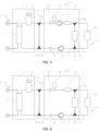
- FIG. 1 schematically shows a first embodiment of the system (1).
- the heat pump system (1) is shown comprising an outdoor unit (3) and an indoor unit (2).
- the heat pump system (2) comprises a refrigerant circuit and a heat medium circuit.
- the refrigerant circuit comprises a compressor (not shown), a refrigerant-side heat exchanger (not shown), an expansion valve (not shown) and a refrigerant circuit side of an intermediate heat exchanger (6) located downstream from the compressor.
- the heat medium circuit comprises a heat medium circuit side of the intermediate heat exchanger (6), a gas-liquid separator (21), a first pump (7) and a load-side heat exchanger (20).
- This first pump (7) ensures a more efficient heat transfer to the indoor space provided with the load-side heat exchanger (20).
- the outdoor unit (3) comprises at least part of a refrigerant circuit (5), and intermediate heat exchanger (6) and a gas-liquid separator (21) equipped with an overpressure valve (22) and a gas-air vent (27).
- the overpressure valve (22) is also called a pressure release valve.
- the gas-air vent (27) is also called a gas release valve.
- the refrigerant circuit (5) is shown passing through one side of the intermediate heat exchanger (6), the second side of said heat exchanger being in fluid contact with a heat medium circuit (4).
- the gas-liquid separator (21) is shown in fluid connection with the outlet of the intermediate heat exchanger (6) and a first of two pipes connecting the outdoor unit (3) with the indoor unit (2).
- the indoor unit (2) is only traversed by the heat medium circuit (4), which heat medium circuit (4) includes a 2-phase sensor (23) capable of detection refrigerant bubbles inside the heat medium circuit (4), an expansion device (24) placed upstream of the inlet side of a first pump (7).
- the 2-phase sensor (23) corresponds to a sensor capable of detecting refrigerant in the heat medium circuit in the claims.
- the 2-phase sensor (23) may be, for example but not limited to, an ultrasonic flow-meter or vortex type flow sensor.
- Ultrasonic flow-meter can be used to measure the flow of the heat medium within the pipes. If gas is present in the heat medium, it can alter the flow characteristics, causing disruptions or changes in the ultrasonic signal.
- Vortex flow sensor also can be used to measure the flow of the heat medium within the pipes. If gas is present in the heat medium, it can alter the flow characteristics, causing disruptions or changes in the vortex frequency. By analyzing these disturbances, it may be possible to detect the presence of gas bubbles within the heat medium.
- These sensors can use various methods such as optical, acoustic, or conductive principles to identify the bubbles.
- the 2-phase sensor (23) is configured to send a signal with information related to the presence of refrigerant in the heat medium circuit to a controller (not shown).
- the controller is configured to send a control signal to each of at least two valves, details of which will be explained later.
- the controller may comprise one or more processing units or modules (e.g. a central processing unit (CPU) such as a microprocessor, or a suitably programmed field programmable gate array (FPGA) or application-specific integrated circuit (ASIC)). Additionally, or alternatively, the controller may be provided with any memory sections necessary to perform its function of controlling operation of the heat pump system. Such memory sections may be provided as part of (comprised in) the controller (e.g. integrally formed or provided on the same chip) or provided separately, but electrically connected to the controller. By way of example, the memory sections may comprise both volatile and non-volatile memory resources, including, for example, a working memory (e.g. a random access memory). In addition, the memory sections may include an instruction store (e.g.
- a ROM in the form of an electrically-erasable programmable read-only memory (EEPROM) or flash memory) storing a computer program comprising computer-readable instructions which, when executed by the controller, cause the controller to perform various functions described herein.
- the controller has instructions, causing it to send a signal to the valves, said signal having information related to an aperture and/or position of for each of said valves.
- the controller is connected to the sensor capable of detecting presence of refrigerant in the heat medium circuit (but if present, also to other sensors, such as the pressure sensor, and any other sensors).
- the controller is furthermore configured for controlling other components of the system, such as the backup heater, the pump(s), etc. This allows the heat pump system to continue (partial) operation even when a refrigerant leak is detected, for instance still allowing hot water to be supplied.
- the outlet side of said first pump (7) is in fluid connection with a backup heater (25) before reaching an upstream first connection portion (11) bifurcating into a first bypass passage (9) on one side and a load-side heat exchanger (20) on the other side.
- a first bypass passage (9) is shown passing through a domestic hot water tank (19) before reaching a downstream first connection portion (12), where also the outlet side of the load-side heat exchanger (20) converges, making sure that the domestic hot water can still be heated with the heat medium in which refrigerant is present, without risking the refrigerant reaching the load-side heat exchanger.
- the piping of the heat medium circuit (4) reaches a pressure sensor (26) before a downstream second connection portion (14) which bifurcates into a second pipe connecting the indoor unit (2) with the outdoor unit (3) on one side, and a second bypass passage (10).
- Said second bypass passage (10) is in fluid connection with an upstream second connection portion (13) reaching a first pipe connecting the indoor unit (2) with the outdoor unit (3), and allows the reverse of the first bypass passage, namely to isolate the heat medium side of the intermediate heat exchanger, from the rest of the heat medium circuit (thus allowing a flow of the heat medium over the load-side heat exchanger and the second bypass passage), thereby allowing partial operability of the heat pump system for the user.
- the second bypass passage (10) may be connected to the first pipe and the second pipe connecting the outdoor unit (3) to the indoor unit (2) outside the outdoor unit and the indoor unit.
- the second bypass passage (10) is shown including a second intermediate two-way valve (33), which valve is closed under normal operation of the system (1). Opening of said second intermediate (two-way) valve (33) is accompanied by the closing of a third two-way valve (31) on the first pipe connecting the indoor unit (2) and the outdoor unit (3), and a fourth two-way valve (32) on the second pipe connecting between said units.
- the third two-way valve (31) corresponds to a third valve in the claim.
- the fourth two-way valve (32) corresponds to a fourth valve in the claim.
- the second intermediate (two-way) valve (33) is arranged in the second bypass passage (10), but it is also possible to have a configuration without a second intermediate (two-way) valve. In this way, a second bypassed circuit is created between the load-side heat exchanger (20) and the second bypass passage (10), said second bypassed circuit is defined by the second bypass loop (35).
- the controller when the controller detects refrigerant leakage into the heat medium circuit during heating operation using a load-side heat exchanger, the controller is configured to close the third two-way valve (31) and the fourth two-way valve (32), open the second intermediate (two-way) valve (33), and operate the pump (7) and backup heater (25). By executing such control, heating operation using the load-side heat exchanger (20) can be continued even when a refrigerant leakage into the heat medium circuit is detected.
- FIG. 2 schematically shows a second embodiment of the system (1).
- the shown system (1) differs from that of the FIG. 1 in that the flow of heat medium through the first and second bypass passages (9, 10) is controlled via six two-way valves (28-33).
- the first two-way valve (28) is located between the upstream first connection portion (11) and the inlet of the load-side heat exchanger (20), the second two-way valve (29) is located between the outlet side of the load-side heat exchanger (20) and the downstream first connection portion (12).
- the first two-way valve (28) corresponds to a first valve in the claim.
- a first intermediate (two-way) valve (30) is located on the first bypass passage (9), upstream of the domestic hot water tank (19).
- the first bypassed circuit is created by opening the first intermediate (two-way) valve (30) and the closing of the first and second two-way valves (28, 29).
- the controller detects refrigerant leakage into the heat medium circuit during defrost operation in the refrigerant-side heat exchanger, the controller is configured to close the first two-way valve (28) and the second two-way valve (29), open the first intermediate (two-way) valve (30), and operate the pump (7) and backup heater (25).
- a third two-way valve (31) is shown located between the outlet of the gas-liquid separator (21) and the upstream second connection portion (13), and the fourth two-way valve (32) is shown located between the downstream second connection portion (14) and the intermediate heat exchanger (6).
- the second bypassed circuit is created by the opening of the second intermediate (two-way) valve (33) on the second bypass passage (10) while closing the third and fourth two-way valves (31, 32).
- the second bypass passage (10), the third two-way valve (31) and the fourth two-way valve (32) are provided in the heat medium circuit in the outdoor unit (3).
- the control of the 3rd two-way valve (31), the 4th two-way valve (32), and the second intermediate (two-way) valve (33) when the controller detects refrigerant leakage into the heat medium circuit during heating operation using a load-side heat exchanger is the same as the first embodiment, so the explanation is omitted.
- FIG. 3 schematically shows a third embodiment of the system (1).
- the system (1) shown in this figure differs from that of FIG. 2 in that the second bypass passage (10) is shown located inside the indoor unit (2).
- FIG. 4 schematically shows a fourth embodiment of the system (1).
- Figure 4 shows the heat-pump system (1) wherein the passage of heat medium through the bypass passages (9, 10) is controlled by means of four three-way valves (15-18).
- the first three-way valve (15) is located on the upstream first connection portion (11), and the second first three-way valve (16) is located on the downstream first connection portion (12).
- the first three-way valve (15) corresponds to a first valve in the claim.
- the second three-way valve (16) corresponds to a second valve in the claim.
- the first bypassed circuit is created when the first and second three-way valves (15-16) redirect the heat medium flow from the load-side heat exchanger (20) towards the first bypass passage (9), and instead a smaller circuit between the first bypass passage (10) and the heat medium side of the intermediate heat exchanger (6) is created.
- the controller detects refrigerant leakage into the heat medium circuit during defrost operation in the refrigerant-side heat exchanger, the controller is configured to switch the first and second three-way valves (15,16) so as to allow the heat medium to the first bypass passage (9), and operate the pump (7) and backup heater (25). By executing such control, defrost operation using the backup heater (25) can be continued even when a refrigerant leakage into the heat medium circuit is detected.
- the third three-way valve (17) is located on the upstream second connection portion (13), and the fourth three-way valve (18) is located on the downstream second connection portion (14).
- the third three-way valve (17) corresponds to a third valve in the claim.
- the fourth three-way valve (18) corresponds to a fourth valve in the claim.
- the second bypassed circuit is created when the third and fourth three-way valves (17, 18) change their position in order to stop the flow of heat medium from the heat medium side of the intermediate heat exchanger (6) towards the rest of the heat medium circuit (4), and instead a smaller circuit between the second bypass passage (10) and the load-side heat exchanger (20) is created.
- the controller when the controller detects refrigerant leakage into the heat medium circuit during heating operation using a load-side heat exchanger, the controller is configured to switch the third and fourth three-way valves (17,18) so as to allow the heat medium to the second bypass passage (10), and operate the pump (7) and backup heater (25). By executing such control, heating operation using the load-side heat exchanger (20) can be continued even when a refrigerant leakage into the heat medium circuit is detected.
- the second bypass passage (10) is connected to the first pipe and the second pipe connecting the outdoor unit (3) to the indoor unit (2) outside the outdoor unit and the indoor unit.
- the first bypass passage (9) and second bypass passage (10) may be provided in the heat medium circuit in the indoor unit (2).
- the first bypass passage (9) may be provided in the heat medium circuit in the indoor unit (2) and the second bypass passage (10) may be provided in the heat medium circuit in the outdoor unit (3).
- FIG. 5 schematically shows a fifth embodiment of the system (1).
- the figure shows a system (1) differing from that of FIG. 4 in that it includes a second pump (8) located between the downstream first connection portion (12) and the downstream second connection portion (14). Furthermore, the second pump (8) is located between the downstream first connection portion (12) and pressure sensor (26).
- the placement of the second pump (8) is also applicable to any of the embodiments disclosed in figures 1-4 without any prejudice to the function of said embodiments of the system.
- the addition of a second pump (8) to any of the aforementioned embodiments advantageously permits compensate any pressure losses occurring in the first bypass branch (9) or load-side heat exchanger (20).
- the controller when the controller detects refrigerant leakage into the heat medium circuit during defrost operation in the refrigerant-side heat exchanger, the controller is configured to switch the first and second three-way valves (15,16) so as to allow the heat medium to the first bypass passage (9), and operate the pump (7) and/or pump (8), and backup heater (25). By executing such control, defrost operation using the backup heater (25) can be continued even when a refrigerant leakage into the heat medium circuit is detected.
- the controller when the controller detects refrigerant leakage into the heat medium circuit during heating operation using a load-side heat exchanger, the controller is configured to switch the third and fourth three-way valves (17,18) so as to allow the heat medium to the second bypass passage (10), and operate the pump (7) and/or pump (8), and backup heater (25).
- the controller By executing such control, heating operation using the load-side heat exchanger (20) can be continued even when a refrigerant leakage into the heat medium circuit is detected.
- FIG. 6 schematically shows a sixth embodiment of the system (1).
- the figure shows the system (1) equipped with only the second pump (8).
- This embodiment of the system (1) advantageously exposes the second pump (8) to heat medium at a much lower temperature, thereby reducing deterioration of the pump (8) and increasing the lifespan of the pump (8), and potentially, the system (1).
- This embodiment is also advantageous, for example, when the heat medium is required to be at a higher temperature that would otherwise damage a pump placed upstream of the load-side heat exchangers (20).
- the controller when the controller detects refrigerant leakage into the heat medium circuit during defrost operation in the refrigerant-side heat exchanger, the controller is configured to switch the first and second three-way valves (15,16) so as to allow the heat medium to the first bypass passage (9), and operate the pump (8), and backup heater (25). By executing such control, defrost operation using the backup heater (25) can be continued even when a refrigerant leakage into the heat medium circuit is detected.
- the controller when the controller detects refrigerant leakage into the heat medium circuit during heating operation using a load-side heat exchanger, the controller is configured to switch the third and fourth three-way valves (17,18) so as to allow the heat medium to the second bypass passage (10), and operate the pump (8), and backup heater (25). By executing such control, heating operation using the load-side heat exchanger (20) can be continued even when a refrigerant leakage into the heat medium circuit is detected.
Landscapes
- Engineering & Computer Science (AREA)
- Physics & Mathematics (AREA)
- Thermal Sciences (AREA)
- Chemical & Material Sciences (AREA)
- Combustion & Propulsion (AREA)
- Mechanical Engineering (AREA)
- General Engineering & Computer Science (AREA)
- Compression-Type Refrigeration Machines With Reversible Cycles (AREA)
Abstract
The present invention concerns a heat pump system having an outdoor unit and an indoor unit sharing a heat medium circuit equipped with at least one bypass passage. Said at least one bypass passage is configured to open if refrigerant is detected in the heat medium circuit. A first bypass passage is laid between the any element on the load-side of the heat medium circuit, in particular, load-side heat exchangers. This permits, avoiding the contamination of indoor rooms with refrigerant, while still allowing the system to be used to heat a domestic hot water tank disposed to the first bypass. A second bypass passage is also foreseen in the heat medium pipes connecting the indoor and outdoor units, the second bypass passage being configured to provide a fluid connection between said pipes. Said second bypass advantageously allows the system to keep providing heat medium to the load-side heat exchanger, a backup heater providing for the heating of the heat medium.
Description
- The present invention relates to a heat pump system. More in particular, the present invention relates to such heat pump system which can permit safe operation of the system. The present invention also relates to a method for operating such heat pump system.
-
JP6575813 -
WO2013038577A1 describes an indirect air conditioning system comprising a refrigerant circuit and a water circuit in thermal communication with one another by means of a heat exchanger. The system disclosed in WO '577 relies on valve regulation as a means to prevent ingress of refrigerant into any indoor units. However, WO '577 does not disclose any method or device capable of continuing operation of the system in a safe mode upon detection of a refrigerant leak. This not only puts a user in danger, it may also further compromise the system, for example, by failing to prevent an outdoor heat exchanger from frosting over and getting damaged in the process. - The present invention aims to resolve at least some of the problems and disadvantages mentioned above. The aim of the invention is to provide a method and system which eliminate those disadvantages.
- The present invention aims to resolve at least some of the problems and disadvantages mentioned above.
- The invention thereto aims to provide a method and system which can not only detect refrigerant leakages on the load-side of the circuit but can also permit safe operation of the system while safely purging the load-side of the system of any leaked refrigerant.
- The present invention and embodiments thereof serve to provide a solution to one or more of above-mentioned disadvantages. To this end, the present invention relates to heat pump system according to
claim 1. - The heat pump system according to
claim 1 comprises: - a refrigerant circuit comprising a compressor, the refrigerant side of an intermediate heat exchanger, an expansion device and a refrigerant-side heat exchanger;
- a heat medium circuit comprising a heat medium circuit side of the intermediate heat exchanger, a pump and a load-side heat exchanger and at least one bypass passage branching the heat medium circuit to connect an output and input ends of the heat medium circuit side of the intermediate heat exchanger, and
- a controller;
- When the controller detects refrigerant leakage in the heat medium circuit, the controller is configured to cause the heat medium to flow in the at least one bypass passage. In this way the heat medium does not flow to the load-side heat exchanger or the intermediate heat exchanger is separated from the heat medium circuit to form an isolated section of the heat medium circuit. This stops the passage of any further refrigerant into the heat medium circuit, or into the load-side heat exchanger. Since any leaked refrigerant is detected very early, any refrigerant that has leaked into the heat medium circuit will be in very low amounts and will not result in sufficient concentrations to cause poisoning nor explosions if leaked out of any load-side heat exchanger on the load-side of the heat medium circuit.
- In an embodiment, the bypass passage comprises a first bypass passage connecting to the heat medium circuit at an upstream first connection portion upstream from the load-side heat exchanger and at a downstream first connection portion downstream from the load-side heat exchanger, a first valve located at or near to the upstream first connection portion and a second valve located at or near to the downstream first connection portion. The controller is configured to, when the controller detects the refrigerant leakage in the heat medium circuit, control the first valve and the second valve so that the heat medium circulates through the first bypass passage and the heat medium circuit side of the intermediate heat exchanger and does not flow to the load-side heat exchanger. The first valve and the second valve may be two-way valves, the first valve being located downstream of the upstream first connection portion (but upstream of the load-side heat exchanger), the second valve being placed upstream of the downstream first connection portions (but downstream of the load-side heat exchanger). In this light, it should be noted that the proximity of the first and second two-way valves to the upstream and downstream first connection portion respectively can be loosely applied, as their function is to shut down flow respectively to and from said upstream and downstream first connection portions. As such, while typically, the first and second two-way valves will be positioned proximate to the upstream and downstream first connection portions for practical reasons, this is not strictly required for their functionality. Preferably, a first intermediate valve is located on the first bypass passage, which is preferably a two-way valve, and may or may not be a solenoid valve. More preferably, either the first or second valves is a three-way valve, between the upstream and the downstream first connection portion. In this way, the placement of a first intermediate valve onto the first bypass passage is advantageously made unnecessary, thus simplifying the construction and control of the system. Most preferably, the first and second valves are both three-way valves. In this way, the construction and control of the system is made advantageously simple while still allowing the flow of heat medium to the load-side of the heat medium circuit to be diverted to the first bypass passage. The use of the first bypass passage effectively prevents the circulation of refrigerant contaminated heat medium from flowing to the load-side of the heat medium circuit, while allowing most of the system to keep working. This is particularly advantageous during cold weather, during which, any outdoor unit of the system is at risk if defrosting is not, at least periodically, carried out. By allowing the compressor to still run, the heat of the compressed refrigerant and/or any heat transmitted back to the refrigerant by the heat medium can be used to defrost any outdoor unit of the system, thereby preventing the system from being damaged by exposure to low temperatures.
- In this context, "upstream first connection portion" is to be understood as the point or zone of connection between the heat medium circuit and the first bypass passage disposed between the intermediate heat exchanger and the load-side heat exchanger, located upstream of the load-side heat exchanger of the heat medium circuit. In this context, "downstream first connection portion" is to be understood as the point or zone of connection between the heat medium circuit and the first bypass passage disposed between the intermediate heat exchanger and the load-side heat exchanger, located downstream of the load-side heat exchanger of the heat medium circuit.
- In an embodiment, the pump is located on the heat medium circuit, wherein the pump is connected to the heat medium circuit upstream of the upstream first connection portion. This allows for an efficient displacement of the heat medium towards and through the load-side heat exchanger, permitting a more efficient heat transfer with an indoor space provided with said heat exchanger.
- In an embodiment, the pump is located on the heat medium circuit, wherein the pump is connected to the heat medium circuit downstream of the downstream first connection portion. In this way, the pump is advantageously located after the load heat exchanger. This permits reduce the temperature of the heat medium received by the pump as a significant amount of heat is dissipated indoors by the load heat exchanger. By reducing the temperature of the fluid passing through the pump, the useful life of the pump is advantageously extended.
- In a further embodiment, the system is provided with two pumps, a first pump is connected to the heat medium circuit and upstream of the upstream first connection portion and upstream of the first bypass passage, wherein a second pump is connected to the heat medium circuit downstream from the first bypass passage. In this way, the first pump ensures a more efficient heat transfer to an indoor space provided with the load-side heat exchanger, while the second pump compensates for any pressure drop caused by the passage of the heat medium through the load-side heat exchanger.
- In an embodiment, the bypass passage comprises a second bypass passage bridging an upper second connection portion and a downstream second connection portion, a third valve located at or near to the upstream second connection portion and a fourth valve located at or near to the downstream second connection portion, and wherein the controller is configured to, when the controller detects the refrigerant leakage in the heat medium circuit, control the third valve and the fourth valve so that the heat medium circulates through the second bypass passage and the load-side heat exchanger and does not flow to the heat medium circuit side of the intermediate heat exchanger. The third valve and the fourth valve may be two-way valves, the third valve being located upstream of the upstream second connection portion, the fourth valve being located downstream of the downstream second connection portion. In this light, it should be noted that the proximity of the third and fourth two-way valves to the upstream and downstream second connection portion respectively can be loosely applied, as their function is to shut down flow respectively to and from said upstream and downstream second connection portions. As such, while typically, the third and fourth two-way valves will be positioned proximate to the upstream and downstream second connection portions for practical reasons, this is not strictly required for their functionality. Preferably, a second intermediate valve is located on the second bypass passage between the upstream and the downstream second connection portion, which is preferably a two-way valve, and may or may not be a solenoid valve. More preferably, either the third or fourth valve is a three-way valve. In this way, the placement of the second intermediate valve onto the second bypass passage is advantageously made unnecessary, thus simplifying the construction and control of the system. Most preferably, the third and fourth valves are both three-way valves. In this way, the construction and control of the system is made advantageously simple while still allowing the flow of heat medium to the load-side of the heat medium circuit to be diverted to the second bypass passage. The use of the second bypass passage effectively prevents the circulation of refrigerant contaminated heat medium from flowing further into the heat medium circuit, while allowing most of the heat medium circuit to keep working. The circuit formed by the second bypass passage and the heat medium circuit downstream of the upstream second connection portion advantageously prevents any refrigerant from reaching the any part of the heat medium circuit beyond the second bypass. Since the detection occur at a very early, the amount of refrigerant reaching past the second bypass is advantageously minimal. Preferably, the heat medium circuit includes , a gas release valve or an overpressure valve, which, in the unlikely event that any refrigerant reaches past the second bypass, advantageously allow said refrigerant to leave the heat medium circuit.
- In this context, "upstream second connection portion" is to be understood as the point or zone of connection between the heat medium circuit and the second bypass passage disposed between the intermediate heat exchanger and the load-side heat exchanger, located upstream of the load-side heat exchanger of the heat medium circuit. In this context, "downstream second connection portion" is to be understood as the point or zone of connection between the heat medium circuit and the second bypass passage disposed between the intermediate heat exchanger and the load-side heat exchanger, located downstream of the load-side heat exchanger of the heat medium circuit.
- In an embodiment, the pump is located on the heat medium circuit upstream from the load-side heat exchanger, wherein the pump is connected to the heat medium circuit downstream of the upstream second connection portion. In this way, the pump is placed before the load-side heat exchanger. This allows for an efficient displacement of the heat medium towards and through the load-side heat exchanger, permitting a more efficient heat transfer with an indoor space provided with said heat exchanger.
- In an embodiment, the pump is located on the heat medium circuit downstream from the load-side heat exchanger, wherein the pump is connected to the heat medium circuit, preferably upstream of the downstream second connection portion. In this way, any pressure loss occurring along or beyond the first bypass passage is advantageously compensated for, allowing the heat medium circuit to maintain an optimal flow of heat medium. This ensures an effective heat transfer between said heat medium/and the refrigerant and/or the rooms served by the load-side heat exchangers.
- In an embodiment, at least one of said first, second, third and fourth valves for controlling heat medium flow is a three-way valve, wherein these three-way valves are located on the first connection portions and the second connection portions. These valves simplify the construction of the system by requiring a lower number of valves with fewer ways. These valves are typically globe valves, therefore requiring an actuator to exert less force to switch them between states, making these valves particularly robust and long lasting.
- In an embodiment, at least one of said first, second, third and fourth valves for controlling heat medium flow is a two-way valve, wherein these two-way valves are located near to the first connection portions and the second connection portions, preferably said two-way valves are solenoid valves. This type of valve are particularly suitable for systems running heating and cooling cycles, in particular if these cycles are run at variable flow rates. These valve advantageously permit increasing process efficiencies, and also the lowering of operating costs.
- In an embodiment, the first, second, third and fourth valves for controlling heat medium flow are all three-way valves. In this way, the system and its control are advantageously simplified. This embodiment is particularly useful in situations where a constant flow of the heat medium is desired.
- In an embodiment, the first, second, third and fourth valves for controlling heat medium flow are all two-way valves. Such a system is highly efficient and is advantageously suitable where variable heat medium flows are desirable. This system has also a very high potential to be less expensive while being also easier to repair.
- In an embodiment, the first bypass passage comprises a domestic hot water tank. In this way, the domestic hot water tank can draw heat from the heat medium when said heat medium is allowed to pass through the first bypass passage. In this way, the domestic hot water tank can safely provide hot water, even is some refrigerant leakage is detected in the heat medium circuit.
- By preference, the first bypass passage comprises a coil shaped section located inside the domestic hot water tank. This advantageously permits increasing the area of the first bypass passage exposed to the water inside said domestic water tank, thereby increasing the heat transferred from the heat medium to the water. In an embodiment, the load-side heat exchanger is in fluid connection with the domestic hot water tank by means of piping, which piping comprises a pump configured to draw water from the domestic hot water tank, pump said water through said heat exchanger and back to said domestic hot water tank. In this way, the heat medium circuit can still heat up the water in the domestic hot water tank, while the water of said domestic hot water tank can still be safely used as heat medium in the load-side heat exchanger. This is possible even if refrigerant has leaked into the heat medium circuit since the heat medium circuit and the water in the domestic hot water tank are only thermally connected, not fluidly connected.
- In an embodiment, the heat medium circuit comprises a backup heater downstream from any pump downstream of the upstream second connection portion and upstream of the upstream first connection portion, said backup heater configured for heating the heat medium passing through said backup heater. In this way, it is advantageously possible to still heat the load-side heat exchanger using the heat provided by the backup heater instead of refrigerant to heat up the heat medium. By preference, the heat pump system comprises at least two power supply modules, wherein, one power supply module is supplies electrical power to the refrigerant circuit only. Most preferably, loss of electrical power to the refrigerant circuit automatically causes the second bypass passage to open. In this way, maintenance work can be safely carried out on the intermediate heat exchanger while, the backup heater ensures heating of the load-side heat exchanger.
- In an embodiment, the heat medium circuit comprises a gas-liquid separator between an outlet of the intermediate heat exchanger and the first and second bypass passages. The gas-liquid separator is preferably equipped with a pressure release valve. The gas-liquid separator advantageously allows any refrigerant leaked into the heat medium circuit to further expand, further increasing the difference between the heat medium density and the refrigerant density. This causes the refrigerant to accumulate above the surface of the heat medium, making the evacuation of said refrigerant easier, while advantageously reducing or even eliminating any refrigerant in the heat medium before said heat medium flows downstream.
- In an embodiment, the heat pump system further comprises:
- an outdoor unit provided with the refrigerant circuit comprising the compressor, the intermediate heat exchanger, the expansion device and the refrigerant-side heat exchanger, and
- an indoor unit provided with a part of the heat medium circuit which comprises the pump, the backup heater and the domestic hot water tank,
- and connected to the load-side heat exchanger.
- The gas-liquid separator is provided in the outdoor unit, and the first and second bypass passages are provided in heat medium circuit in the indoor unit. In this way, the system is advantageously provided in separable units, making installation, maintenance and substitution advantageously easy. By providing the gas-liquid separator in the outdoor unit, any refrigerant gas trapped by said gas-liquid separator can be safely vented out.
- In an embodiment, the heat medium circuit comprises a sensor capable of detecting refrigerant in the heat medium circuit, the sensor being configured to send a signal with information related to the presence of refrigerant in the heat medium circuit to the controller, the controller being configured to send a control signal to each of at least two valves, at least one of said valves on each side of the bypass passage, the control signal having information related to an aperture/ and/or position of each of said valves to cause the heat medium to flow in the bypass passage. By preference, by diverting the heat medium to flow to the bypass passage, said heat medium bypasses the load-side heat exchanger. In this way, any leaked refrigerant reaching an upstream connection portion (which connects the bypass passage to the heat medium circuit upstream from the load-side heat exchanger) along with the heat medium is advantageously prevented from entering the load-side heat exchanger and from being released into any indoor room. While passing through the bypass passage, the heat medium can still safely heat up the contents of the domestic hot water tank, the inside of which domestic hot water tank is preferably in fluid connection with the load-side heat exchanger via piping equipped with a pump. In this way, the hot water inside of the domestic hot water tank can still be used to heat up the load-side heat exchanger. The sensor used to detect the presence of refrigerant inside the heat medium circuit may be an acoustic sensor configured to detect the presence of gas bubbles inside the piping. The sensor may also be a pressure sensor disposed to the piping and/or the expansion device and/or the gas-liquid separator. By preference, if the overpressure valve is a controllable overpressure valve, any sensor capable of detecting refrigerant in the heat medium circuit is configured to send a signal to the controllable overpressure valves placed at least on the liquid gas separator and/or the expansion device. Said signal comprising information related to the opening of any said overpressure valves. This advantageously permits automating purging of the heat medium circuit in the event of refrigerant leakage into the heat medium circuit.
- The present invention is also reached by a method of operating the heat pump, preferably the heat pump of according to
claim 1, the method being according toclaim 15. - The method for operating a heat pump system having a refrigerant circuit and a heat medium circuit in connection with an intermediate heat exchanger, the method comprising the steps of:
- detecting refrigerant in the heat medium circuit via a sensor in the heat medium circuit;
- providing information regarding the presence of the refrigerant in the heat medium circuit from the sensor to a controller in a first signal;
- A bypass passage is provided branching the heat medium circuit to connect an output and input end of the heat medium circuit side of the intermediate heat exchanger with respect to the intermediate heat exchanger, wherein the controller is configured to send a control signal to each of at least two valves, at least one of said valves on an inlet and outlet side of the bypass passage, the control signal having information related to an aperture and/or position for each of said valves, to cause the heat medium to flow from the intermediate heat exchanger in the bypass passage.
- In an embodiment, the bypass passage comprises a first bypass passage, and opening of the first bypass passage causes the passage of heat medium to the load-side heat exchanger to stop. The use of the fist bypass passage effectively prevents the circulation of refrigerant contaminated heat medium from flowing to the load-side of the heat medium circuit, while allowing most of the system to keep working. This is particularly advantageous during cold weather, during which, any outdoor unit of the system is at risk if defrosting is not, at least periodically, carried out. By allowing the compressor to still run, the heat of the compressed refrigerant and/or any heat transmitted back to the refrigerant by the heat medium can be used to defrost any outdoor unit of the system, thereby preventing the system from being damaged by exposure to low temperatures.
- In an embodiment, the bypass passage comprises a second bypass passage, and opening of the second bypass passage causes the passage of heat medium to the intermediate heat exchanger to stop.
- By preference, the heat medium circuit comprises a backup heater downstream from the pump and upstream from the bypass passage, and wherein, after opening of the bypass passage, the controller triggers the backup heater to start heating the heat medium passing through said backup heater. In this way, it is advantageously possible to still heat the load-side heat exchanger using the heat provided by the backup heater instead of refrigerant to heat up the heat medium. Most preferably, the backup heater is positioned downstream of the point where the second bypass passage connects to the heat medium circuit upstream of the load-side heat exchanger, said point having been described as the upstream second connection portion previously.
- The following description of the figures of specific embodiments of the invention is merely exemplary in nature and is not intended to limit the present teachings, their application or uses. Throughout the drawings, corresponding reference numerals indicate like or corresponding parts and features.
-
Figure 1 schematically shows a first embodiment of the system (1). -
Figure 2 schematically shows a second embodiment of the system (1). -
Figure 3 schematically shows a third embodiment of the system (1). -
Figure 4 schematically shows a fourth embodiment of the system (1). -
Figure 5 schematically shows a fifth embodiment of the system (1). -
Figure 6 schematically shows a sixth embodiment of the system (1). - The invention is further described by the following non-limiting examples which further illustrate the invention, and are not intended to, nor should they be interpreted to, limit the scope of the invention.
- The present invention concerns a heat pump system having an outdoor unit and an indoor unit sharing a heat medium circuit equipped with at least one bypass passage. Said at least one bypass passage is configured to open if refrigerant is detected in the heat medium circuit. A first bypass passage is laid between the any element on the load-side of the heat medium circuit, in particular, load-side heat exchangers. This permits, avoiding the contamination of indoor rooms with refrigerant, while still allowing the system to be used to heat a domestic hot water tank disposed to the first bypass. A second bypass passage is also foreseen in the heat medium pipes connecting the indoor and outdoor units, the second bypass passage being configured to provide a fluid connection between said pipes. Said second bypass advantageously allows the system to keep providing heat medium to the load-side heat exchanger, a backup heater providing for the heating of the heat medium.
- Unless otherwise defined, all terms used in disclosing the invention, including technical and scientific terms, have the meaning as commonly understood by one of ordinary skill in the art to which this invention belongs. By means of further guidance, term definitions are included to better appreciate the teaching of the present invention.
- As used herein, the following terms have the following meanings:
"A", "an", and "the" as used herein refers to both singular and plural referents unless the context clearly dictates otherwise. By way of example, "a compartment" refers to one or more than one compartment. - "About" as used herein referring to a measurable value such as a parameter, an amount, a temporal duration, and the like, is meant to encompass variations of +/-20% or less, preferably +/-10% or less, more preferably +/-5% or less, even more preferably +/-1% or less, and still more preferably +/-0.1% or less of and from the specified value, in so far such variations are appropriate to perform in the disclosed invention. However, it is to be understood that the value to which the modifier "about" refers is itself also specifically disclosed.
- "Comprise", "comprising", and "comprises" and "comprised of" as used herein are synonymous with "include", "including", "includes" or "contain", "containing", "contains" and are inclusive or open-ended terms that specifies the presence of what follows e.g. component and do not exclude or preclude the presence of additional, non-recited components, features, element, members, steps, known in the art or disclosed therein.
- Furthermore, the terms first, second, third and the like in the description and in the claims, are used for distinguishing between similar elements and not necessarily for describing a sequential or chronological order, unless specified. It is to be understood that the terms so used are interchangeable under appropriate circumstances and that the embodiments of the invention described herein are capable of operation in other sequences than described or illustrated herein.
- The recitation of numerical ranges by endpoints includes all numbers and fractions subsumed within that range, as well as the recited endpoints.
- Whereas the terms "one or more" or "at least one", such as one or more or at least one member(s) of a group of members, is clear per se, by means of further exemplification, the term encompasses inter alia a reference to any one of said members, or to any two or more of said members, such as, e.g., any ≥3, ≥4, ≥5, ≥6 or ≥7 etc. of said members, and up to all said members.
- Unless otherwise defined, all terms used in disclosing the invention, including technical and scientific terms, have the meaning as commonly understood by one of ordinary skill in the art to which this invention belongs. By means of further guidance, definitions for the terms used in the description are included to better appreciate the teaching of the present invention. The terms or definitions used herein are provided solely to aid in the understanding of the invention.
- Reference throughout this specification to "one embodiment" or "an embodiment" means that a particular feature, structure or characteristic described in connection with the embodiment is included in at least one embodiment of the present invention. Thus, appearances of the phrases "in one embodiment" or "in an embodiment" in various places throughout this specification are not necessarily all referring to the same embodiment, but may. Furthermore, the particular features, structures or characteristics may be combined in any suitable manner, as would be apparent to a person skilled in the art from this disclosure, in one or more embodiments. Furthermore, while some embodiments described herein include some but not other features included in other embodiments, combinations of features of different embodiments are meant to be within the scope of the invention, and form different embodiments, as would be understood by those in the art. For example, in the following claims, any of the claimed embodiments can be used in any combination.
- With as a goal illustrating better the properties of the invention the following presents, as an example and limiting in no way other potential applications, a description of a number of preferred embodiments of the heat pump system based on the invention, wherein:
FIG. 1 schematically shows a first embodiment of the system (1). The heat pump system (1) is shown comprising an outdoor unit (3) and an indoor unit (2). The heat pump system (2) comprises a refrigerant circuit and a heat medium circuit. The refrigerant circuit comprises a compressor (not shown), a refrigerant-side heat exchanger (not shown), an expansion valve (not shown) and a refrigerant circuit side of an intermediate heat exchanger (6) located downstream from the compressor. The heat medium circuit comprises a heat medium circuit side of the intermediate heat exchanger (6), a gas-liquid separator (21), a first pump (7) and a load-side heat exchanger (20). This first pump (7) ensures a more efficient heat transfer to the indoor space provided with the load-side heat exchanger (20). The outdoor unit (3) comprises at least part of a refrigerant circuit (5), and intermediate heat exchanger (6) and a gas-liquid separator (21) equipped with an overpressure valve (22) and a gas-air vent (27). The overpressure valve (22) is also called a pressure release valve. The gas-air vent (27) is also called a gas release valve. The refrigerant circuit (5) is shown passing through one side of the intermediate heat exchanger (6), the second side of said heat exchanger being in fluid contact with a heat medium circuit (4). The gas-liquid separator (21) is shown in fluid connection with the outlet of the intermediate heat exchanger (6) and a first of two pipes connecting the outdoor unit (3) with the indoor unit (2). The indoor unit (2) is only traversed by the heat medium circuit (4), which heat medium circuit (4) includes a 2-phase sensor (23) capable of detection refrigerant bubbles inside the heat medium circuit (4), an expansion device (24) placed upstream of the inlet side of a first pump (7). The 2-phase sensor (23) corresponds to a sensor capable of detecting refrigerant in the heat medium circuit in the claims. The 2-phase sensor (23) may be, for example but not limited to, an ultrasonic flow-meter or vortex type flow sensor. Ultrasonic flow-meter can be used to measure the flow of the heat medium within the pipes. If gas is present in the heat medium, it can alter the flow characteristics, causing disruptions or changes in the ultrasonic signal. Vortex flow sensor also can be used to measure the flow of the heat medium within the pipes. If gas is present in the heat medium, it can alter the flow characteristics, causing disruptions or changes in the vortex frequency. By analyzing these disturbances, it may be possible to detect the presence of gas bubbles within the heat medium. These sensors can use various methods such as optical, acoustic, or conductive principles to identify the bubbles. The 2-phase sensor (23) is configured to send a signal with information related to the presence of refrigerant in the heat medium circuit to a controller (not shown). The controller is configured to send a control signal to each of at least two valves, details of which will be explained later. - The controller may comprise one or more processing units or modules (e.g. a central processing unit (CPU) such as a microprocessor, or a suitably programmed field programmable gate array (FPGA) or application-specific integrated circuit (ASIC)). Additionally, or alternatively, the controller may be provided with any memory sections necessary to perform its function of controlling operation of the heat pump system. Such memory sections may be provided as part of (comprised in) the controller (e.g. integrally formed or provided on the same chip) or provided separately, but electrically connected to the controller. By way of example, the memory sections may comprise both volatile and non-volatile memory resources, including, for example, a working memory (e.g. a random access memory). In addition, the memory sections may include an instruction store (e.g. a ROM in the form of an electrically-erasable programmable read-only memory (EEPROM) or flash memory) storing a computer program comprising computer-readable instructions which, when executed by the controller, cause the controller to perform various functions described herein. In an embodiment, the controller has instructions, causing it to send a signal to the valves, said signal having information related to an aperture and/or position of for each of said valves. Furthermore, the controller is connected to the sensor capable of detecting presence of refrigerant in the heat medium circuit (but if present, also to other sensors, such as the pressure sensor, and any other sensors). The controller is furthermore configured for controlling other components of the system, such as the backup heater, the pump(s), etc. This allows the heat pump system to continue (partial) operation even when a refrigerant leak is detected, for instance still allowing hot water to be supplied.
- The outlet side of said first pump (7) is in fluid connection with a backup heater (25) before reaching an upstream first connection portion (11) bifurcating into a first bypass passage (9) on one side and a load-side heat exchanger (20) on the other side. This allows the heat pump system to isolate the load-side heat exchanger from the rest of the heat medium circuit in case of refrigerant presence in the heat medium circuit. The first bypass passage (9) is shown passing through a domestic hot water tank (19) before reaching a downstream first connection portion (12), where also the outlet side of the load-side heat exchanger (20) converges, making sure that the domestic hot water can still be heated with the heat medium in which refrigerant is present, without risking the refrigerant reaching the load-side heat exchanger. From the downstream first connection portion (12), the piping of the heat medium circuit (4) reaches a pressure sensor (26) before a downstream second connection portion (14) which bifurcates into a second pipe connecting the indoor unit (2) with the outdoor unit (3) on one side, and a second bypass passage (10). Said second bypass passage (10) is in fluid connection with an upstream second connection portion (13) reaching a first pipe connecting the indoor unit (2) with the outdoor unit (3), and allows the reverse of the first bypass passage, namely to isolate the heat medium side of the intermediate heat exchanger, from the rest of the heat medium circuit (thus allowing a flow of the heat medium over the load-side heat exchanger and the second bypass passage), thereby allowing partial operability of the heat pump system for the user. The flow of heat medium through the first bypass passage (9) is controlled via a first three-way valve (15) located on the upstream first connection portion (11), which allows the heat medium flow to be diverted from the load-side heat exchanger (20) to said first bypass passage (9). The first three-way valve (15) corresponds to a first valve in the claim. The switching of the first three-way valve (15) towards the first bypass passage (9) causes the closing of a second two-way valve (29) on the outlet side of the load-side heat exchanger (20) and upstream of the downstream first connection portion (12). The second two-way valve (29) corresponds to a second valve in the claim. In this way, a first bypassed circuit is created, wherein the load-side heat exchanger (20) is completely avoided. Said first bypassed circuit is defined by the first bypass loop (34). In the first embodiment, the first bypass passage (9) and second bypass passage (10) are provided in the heat medium circuit in the indoor unit (2). For example, when the controller detects refrigerant leakage into the heat medium circuit during defrost operation in the refrigerant-side heat exchanger, the controller is configured to switch the first three-way valve (15) so as to allow the heat medium to the first bypass passage (9), close the second two-way valve (29), and operate the pump (7) and backup heater (25).
- By executing such control, defrost operation using the backup heater (25) can be continued even when a refrigerant leakage into the heat medium circuit is detected. Also, the second bypass passage (10) may be connected to the first pipe and the second pipe connecting the outdoor unit (3) to the indoor unit (2) outside the outdoor unit and the indoor unit. The second bypass passage (10) is shown including a second intermediate two-way valve (33), which valve is closed under normal operation of the system (1). Opening of said second intermediate (two-way) valve (33) is accompanied by the closing of a third two-way valve (31) on the first pipe connecting the indoor unit (2) and the outdoor unit (3), and a fourth two-way valve (32) on the second pipe connecting between said units. The third two-way valve (31) corresponds to a third valve in the claim. Also, the fourth two-way valve (32) corresponds to a fourth valve in the claim. In this embodiment, it was explained using an example where the second intermediate (two-way) valve (33) is arranged in the second bypass passage (10), but it is also possible to have a configuration without a second intermediate (two-way) valve. In this way, a second bypassed circuit is created between the load-side heat exchanger (20) and the second bypass passage (10), said second bypassed circuit is defined by the second bypass loop (35). For example, when the controller detects refrigerant leakage into the heat medium circuit during heating operation using a load-side heat exchanger, the controller is configured to close the third two-way valve (31) and the fourth two-way valve (32), open the second intermediate (two-way) valve (33), and operate the pump (7) and backup heater (25). By executing such control, heating operation using the load-side heat exchanger (20) can be continued even when a refrigerant leakage into the heat medium circuit is detected.
-
FIG. 2 schematically shows a second embodiment of the system (1). The shown system (1) differs from that of theFIG. 1 in that the flow of heat medium through the first and second bypass passages (9, 10) is controlled via six two-way valves (28-33). The first two-way valve (28) is located between the upstream first connection portion (11) and the inlet of the load-side heat exchanger (20), the second two-way valve (29) is located between the outlet side of the load-side heat exchanger (20) and the downstream first connection portion (12). The first two-way valve (28) corresponds to a first valve in the claim. A first intermediate (two-way) valve (30) is located on the first bypass passage (9), upstream of the domestic hot water tank (19). In this embodiment, it was explained using an example where the first intermediate (two-way) valve (30) is arranged in the first bypass passage (9), but it is also possible to have a configuration without a first intermediate (two-way) valve. The first bypassed circuit is created by opening the first intermediate (two-way) valve (30) and the closing of the first and second two-way valves (28, 29). For example, when the controller detects refrigerant leakage into the heat medium circuit during defrost operation in the refrigerant-side heat exchanger, the controller is configured to close the first two-way valve (28) and the second two-way valve (29), open the first intermediate (two-way) valve (30), and operate the pump (7) and backup heater (25). By executing such control, defrost operation using the backup heater (25) can be continued even when a refrigerant leakage into the heat medium circuit is detected. A third two-way valve (31) is shown located between the outlet of the gas-liquid separator (21) and the upstream second connection portion (13), and the fourth two-way valve (32) is shown located between the downstream second connection portion (14) and the intermediate heat exchanger (6). The second bypassed circuit is created by the opening of the second intermediate (two-way) valve (33) on the second bypass passage (10) while closing the third and fourth two-way valves (31, 32). In the second embodiment, the second bypass passage (10), the third two-way valve (31) and the fourth two-way valve (32) are provided in the heat medium circuit in the outdoor unit (3). The control of the 3rd two-way valve (31), the 4th two-way valve (32), and the second intermediate (two-way) valve (33) when the controller detects refrigerant leakage into the heat medium circuit during heating operation using a load-side heat exchanger is the same as the first embodiment, so the explanation is omitted. -
FIG. 3 schematically shows a third embodiment of the system (1). The system (1) shown in this figure differs from that ofFIG. 2 in that the second bypass passage (10) is shown located inside the indoor unit (2). -
FIG. 4 schematically shows a fourth embodiment of the system (1).Figure 4 shows the heat-pump system (1) wherein the passage of heat medium through the bypass passages (9, 10) is controlled by means of four three-way valves (15-18). The first three-way valve (15) is located on the upstream first connection portion (11), and the second first three-way valve (16) is located on the downstream first connection portion (12). The first three-way valve (15) corresponds to a first valve in the claim. The second three-way valve (16) corresponds to a second valve in the claim. The first bypassed circuit is created when the first and second three-way valves (15-16) redirect the heat medium flow from the load-side heat exchanger (20) towards the first bypass passage (9), and instead a smaller circuit between the first bypass passage (10) and the heat medium side of the intermediate heat exchanger (6) is created. For example, when the controller detects refrigerant leakage into the heat medium circuit during defrost operation in the refrigerant-side heat exchanger, the controller is configured to switch the first and second three-way valves (15,16) so as to allow the heat medium to the first bypass passage (9), and operate the pump (7) and backup heater (25). By executing such control, defrost operation using the backup heater (25) can be continued even when a refrigerant leakage into the heat medium circuit is detected. The third three-way valve (17) is located on the upstream second connection portion (13), and the fourth three-way valve (18) is located on the downstream second connection portion (14). The third three-way valve (17) corresponds to a third valve in the claim. The fourth three-way valve (18) corresponds to a fourth valve in the claim. The second bypassed circuit is created when the third and fourth three-way valves (17, 18) change their position in order to stop the flow of heat medium from the heat medium side of the intermediate heat exchanger (6) towards the rest of the heat medium circuit (4), and instead a smaller circuit between the second bypass passage (10) and the load-side heat exchanger (20) is created. For example, when the controller detects refrigerant leakage into the heat medium circuit during heating operation using a load-side heat exchanger, the controller is configured to switch the third and fourth three-way valves (17,18) so as to allow the heat medium to the second bypass passage (10), and operate the pump (7) and backup heater (25). By executing such control, heating operation using the load-side heat exchanger (20) can be continued even when a refrigerant leakage into the heat medium circuit is detected. In the fourth embodiment, the second bypass passage (10) is connected to the first pipe and the second pipe connecting the outdoor unit (3) to the indoor unit (2) outside the outdoor unit and the indoor unit. Also, the first bypass passage (9) and second bypass passage (10) may be provided in the heat medium circuit in the indoor unit (2). Furthermore, the first bypass passage (9) may be provided in the heat medium circuit in the indoor unit (2) and the second bypass passage (10) may be provided in the heat medium circuit in the outdoor unit (3). -
FIG. 5 schematically shows a fifth embodiment of the system (1). The figure shows a system (1) differing from that ofFIG. 4 in that it includes a second pump (8) located between the downstream first connection portion (12) and the downstream second connection portion (14). Furthermore, the second pump (8) is located between the downstream first connection portion (12) and pressure sensor (26). The placement of the second pump (8) is also applicable to any of the embodiments disclosed infigures 1-4 without any prejudice to the function of said embodiments of the system. On the contrary, the addition of a second pump (8) to any of the aforementioned embodiments, advantageously permits compensate any pressure losses occurring in the first bypass branch (9) or load-side heat exchanger (20). For example, when the controller detects refrigerant leakage into the heat medium circuit during defrost operation in the refrigerant-side heat exchanger, the controller is configured to switch the first and second three-way valves (15,16) so as to allow the heat medium to the first bypass passage (9), and operate the pump (7) and/or pump (8), and backup heater (25). By executing such control, defrost operation using the backup heater (25) can be continued even when a refrigerant leakage into the heat medium circuit is detected. For example, when the controller detects refrigerant leakage into the heat medium circuit during heating operation using a load-side heat exchanger, the controller is configured to switch the third and fourth three-way valves (17,18) so as to allow the heat medium to the second bypass passage (10), and operate the pump (7) and/or pump (8), and backup heater (25). By executing such control, heating operation using the load-side heat exchanger (20) can be continued even when a refrigerant leakage into the heat medium circuit is detected. -
FIG. 6 schematically shows a sixth embodiment of the system (1). The figure shows the system (1) equipped with only the second pump (8).This embodiment of the system (1) advantageously exposes the second pump (8) to heat medium at a much lower temperature, thereby reducing deterioration of the pump (8) and increasing the lifespan of the pump (8), and potentially, the system (1). This embodiment is also advantageous, for example, when the heat medium is required to be at a higher temperature that would otherwise damage a pump placed upstream of the load-side heat exchangers (20). For example, when the controller detects refrigerant leakage into the heat medium circuit during defrost operation in the refrigerant-side heat exchanger, the controller is configured to switch the first and second three-way valves (15,16) so as to allow the heat medium to the first bypass passage (9), and operate the pump (8), and backup heater (25). By executing such control, defrost operation using the backup heater (25) can be continued even when a refrigerant leakage into the heat medium circuit is detected. For example, when the controller detects refrigerant leakage into the heat medium circuit during heating operation using a load-side heat exchanger, the controller is configured to switch the third and fourth three-way valves (17,18) so as to allow the heat medium to the second bypass passage (10), and operate the pump (8), and backup heater (25). By executing such control, heating operation using the load-side heat exchanger (20) can be continued even when a refrigerant leakage into the heat medium circuit is detected. -
- 1
- system
- 2
- indoor unit
- 3
- outdoor unit
- 4
- heat medium circuit
- 5
- refrigerant circuit
- 6
- intermediate heat exchanger
- 7
- first pump
- 8
- second pump
- 9
- first bypass passage
- 10
- second bypass passage
- 11
- upstream first connection portion
- 12
- downstream first connection portion
- 13
- upstream second connection portion
- 14
- downstream second connection portion
- 15
- first three-way valve
- 16
- second three-way valve
- 17
- third three-way valve
- 18
- fourth three-way valve
- 19
- domestic hot water tank
- 20
- load-side heat exchanger
- 21
- gas-liquid separator
- 22
- overpressure valve
- 23
- 2-phase sensor
- 24
- expansion device
- 25
- backup heater
- 26
- pressure sensor
- 27
- gas/air vent
- 28
- first two-way valve
- 29
- second two-way valve
- 30
- first intermediate (two-way) valve
- 31
- third two-way valve
- 32
- fourth two-way valve
- 33
- second intermediate (two-way) valve
- 34
- first bypass loop
- 35
- second bypass loop
- The present invention will be now described in more details, referring to examples that are not limitative.
Claims (17)
- A heat pump system comprising:a refrigerant circuit comprising a compressor, a refrigerant circuit side of an intermediate heat exchanger, an expansion device and a refrigerant-side heat exchanger;a heat medium circuit comprising a heat medium circuit side of the intermediate heat exchanger, a pump and a load-side heat exchanger and at least one bypass passage branching the heat medium circuit to connect an output and input ends of the heat medium circuit side of the intermediate heat exchanger, anda controller;characterized in that, when the controller detects refrigerant leakage in the heat medium circuit, the controller is configured to cause the heat medium to flow in the bypass passage so that the heat medium does not flow to the load-side heat exchanger or the intermediate heat exchanger is separated from the heat medium circuit to form an isolated section of the heat medium circuit.
- The heat pump system according to the previous claim 1, characterized in that, the bypass passage comprises a first bypass passage connecting to the heat medium circuit at an upstream first connection portion upstream from the load-side heat exchanger and at a downstream first connection portion downstream from the load-side heat exchanger, a first valve located at or near to said upstream first connection portion and a second valve located at or near to said downstream first connection portion, and wherein the controller is configured to, when the controller detects the refrigerant leakage in the heat medium circuit, control the first valve and the second valve so that the heat medium circulates through the first bypass passage and the heat medium circuit side of the intermediate heat exchanger, and does not flow to the load-side heat exchanger.
- The heat pump system according to the previous claim 2, characterized in that, a first intermediate valve is located on the first bypass passage, between the upstream and the downstream first connection portion.
- The heat pump system according to any of the previous claims 2 or 3, characterized in that, the pump is located on the heat medium circuit, wherein the pump is connected to the heat medium circuit upstream of the upstream first connection portion.
- The heat pump system according to any of the previous claims 1 to 4, characterized in that, the bypass passage comprises a second bypass passage connecting to the heat medium circuit at an upstream second connection portion upstream from the load-side heat exchanger and at a downstream second connection portion downstream from the load-side heat exchanger, a third valve located at or near to the upstream second connection portion and a fourth valve located at or near to the downstream second connection portion, and wherein the controller is configured to, when the controller detects the refrigerant leakage in the heat medium circuit, control the third valve and the fourth valve so that the heat medium circulates through the second bypass passage and the load-side heat exchanger and does not flow to the heat medium circuit side of the intermediate heat exchanger.
- The heat pump system according to the previous claim 5, characterized in that, a second intermediate valve is located on the second bypass passage, between the upstream and the downstream second connection portion.
- The heat pump system according to any of the previous claims 5 or 6, characterized in that, the pump is located on the heat medium circuit upstream from the load-side heat exchanger, wherein the pump is connected to the heat medium circuit downstream of the upstream second connection portion.
- The heat pump system according to any of the previous claims 5 to 7, characterized in that the bypass passage comprises a first bypass passage connecting to the heat medium circuit at an upstream first connection portion upstream from the load-side heat exchanger and at a downstream first connection portion downstream from the load-side heat exchanger, a first valve located at or near said upstream first connection portion and a second valve located at or near to said downstream first connection portion, and wherein the controller is configured to, when the controller detects the refrigerant leakage in the heat medium circuit, control the first valve and the second valve so that the heat medium circulates through the first bypass passage and the heat medium circuit side of the intermediate heat exchanger, and does not flow to the load-side heat exchanger, and in that at least one of said first, second, third and fourth valves for controlling heat medium flow is a three-way valve, wherein these three-way valves are disposed located at the first connection portions and the second connection portions, preferably wherein the first, second, third and fourth valves for controlling heat medium flow are all three-way valves.
- The heat pump system according to any of the previous claims 5 to 8, characterized in that, the bypass passage comprises a first bypass passage connecting to the heat medium circuit at an upstream first connection portion upstream from the load-side heat exchanger and at a downstream first connection portion downstream from the load-side heat exchanger, a first valve located at or near said upstream first connection portion and a second valve located at or near to said downstream first connection portion, and wherein the controller is configured to, when the controller detects the refrigerant leakage in the heat medium circuit, control the first valve and the second valve so that the heat medium circulates through the first bypass passage and the heat medium circuit side of the intermediate heat exchanger, and does not flow to the load-side heat exchanger, and in that the heat medium circuit comprises a backup heater downstream from any pump downstream of the upstream second connection portion, the backup heater being located upstream of said upstream first connection portion, said backup heater configured for heating the heat medium passing through said backup heater.
- The heat pump system according to any of the previous claims 5 to 9, characterized in that, the bypass passage comprises a first bypass passage connecting to the heat medium circuit at an upstream first connection portion upstream from the load-side heat exchanger and at a downstream first connection portion downstream from the load-side heat exchanger, a first valve located at or near said upstream first connection portion and a second valve located at or near to said downstream first connection portion, and wherein the controller is configured to, when the controller detects the refrigerant leakage in the heat medium circuit, control the first valve and the second valve so that the heat medium circulates through the first bypass passage and the heat medium circuit side of the intermediate heat exchanger, and does not flow to the load-side heat exchanger, and in that the heat medium circuit comprises a gas-liquid separator between an outlet of the intermediate heat exchanger and the first and second bypass passages.
- The heat pump system according to any of the previous claims 5 to 10, characterized in that, the bypass passage comprises a first bypass passage connecting to the heat medium circuit at an upstream first connection portion upstream from the load-side heat exchanger and at a downstream first connection portion downstream from the load-side heat exchanger, a first valve located at or near said upstream first connection portion and a second valve located at or near to said downstream first connection portion, and wherein the controller is configured to, when the controller detects the refrigerant leakage in the heat medium circuit, control the first valve and the second valve so that the heat medium circulates through the first bypass passage and the heat medium circuit side of the intermediate heat exchanger, and does not flow to the load-side heat exchanger, and in that the heat pump system comprises:an outdoor unit provided with the refrigerant circuit comprising the compressor, the intermediate heat exchanger, the expansion device and the refrigerant-side heat exchanger, andan indoor unit provided with a part of the heat medium circuit which comprises the pump, the backup heater and the domestic hot water tank, and connected to the load-side heat exchanger, and wherein,the gas-liquid separator is provided in the outdoor unit, andthe first and second bypass passages are provided in heat medium circuit in the indoor unit.
- The heat pump system according to any of the previous claims 1 to 11, characterized in that the bypass passage comprises a first bypass passage connecting to the heat medium circuit at an upstream first connection portion upstream from the load-side heat exchanger and at a downstream first connection portion downstream from the load-side heat exchanger, a first valve located at or near said upstream first connection portion and a second valve located at or near to said downstream first connection portion, and wherein the controller is configured to, when the controller detects the refrigerant leakage in the heat medium circuit, control the first valve and the second valve so that the heat medium circulates through the first bypass passage and the heat medium circuit side of the intermediate heat exchanger, and does not flow to the load-side heat exchanger, and in that the first bypass passage comprises a domestic hot water tank.
- The heat pump system according to the previous claim 12, characterized in that, the first bypass passage comprises a coil shaped section located inside the domestic hot water tank.
- The heat pump system according to any of the previous claims 1 to 13, wherein the heat medium circuit comprises a sensor capable of detecting refrigerant in the heat medium circuit, the sensor being configured to send a signal with information related to the presence of refrigerant in the heat medium circuit to the controller, the controller being configured to send a control signal to each of at least two valves, at least one of said valves on each side of the bypass passage, the control signal having information related to an aperture/ and/or position of for each of said valves to cause the heat medium to flow in the bypass passage.
- A method for operating a heat pump system having a refrigerant circuit and a heat medium circuit in connection with an intermediate heat exchanger, the method comprising the steps of:detecting refrigerant in the heat medium circuit via a sensor in the heat medium circuit;providing information regarding the presence of the refrigerant in the heat medium circuit from the sensor to a controller in a first signal;characterized in that a bypass passage is provided branching the heat medium circuit to connect an output and input end of a heat medium circuit side of the intermediate heat exchanger with respect to the intermediate heat exchanger, andin that the controller is configured to send a control signal to each of at least two valves, at least one of said valves on an inlet and outlet side of the bypass passage, the control signal having information related to an aperture and/or position for each of said valves, to cause the heat medium to flow from the intermediate heat exchanger in the bypass passage.
- The method according to the previous claim 15, characterized in that, the bypass passage comprises a first bypass passage, and opening of the first bypass passage causes the passage of heat medium to the load-side heat exchanger to stop, and/or in that, the bypass passage comprises a second bypass passage, and opening of the second bypass passage causes the passage of heat medium to the intermediate heat exchanger to stop.
- The method according to any of the previous claims 15 or 16, characterized in that, the heat medium circuit comprises a backup heater downstream from the pump and upstream from the bypass passage, and wherein, after opening of the bypass passage, the controller triggers the backup heater to start heating the heat medium passing through said backup heater.
Priority Applications (1)
| Application Number | Priority Date | Filing Date | Title |
|---|---|---|---|
| EP23193311.0A EP4513103A1 (en) | 2023-08-24 | 2023-08-24 | Heat pump system and method for operating heat pump system |
Applications Claiming Priority (1)
| Application Number | Priority Date | Filing Date | Title |
|---|---|---|---|
| EP23193311.0A EP4513103A1 (en) | 2023-08-24 | 2023-08-24 | Heat pump system and method for operating heat pump system |
Publications (1)
| Publication Number | Publication Date |
|---|---|
| EP4513103A1 true EP4513103A1 (en) | 2025-02-26 |
Family
ID=87801648
Family Applications (1)
| Application Number | Title | Priority Date | Filing Date |
|---|---|---|---|
| EP23193311.0A Pending EP4513103A1 (en) | 2023-08-24 | 2023-08-24 | Heat pump system and method for operating heat pump system |
Country Status (1)
| Country | Link |
|---|---|
| EP (1) | EP4513103A1 (en) |
Citations (5)
| Publication number | Priority date | Publication date | Assignee | Title |
|---|---|---|---|---|
| WO2013038577A1 (en) | 2011-09-13 | 2013-03-21 | 三菱電機株式会社 | Heat pump device and method for controlling heat pump device |
| WO2018154628A1 (en) * | 2017-02-21 | 2018-08-30 | 三菱電機株式会社 | Air conditioning device |
| WO2019003268A1 (en) * | 2017-06-26 | 2019-01-03 | 三菱電機株式会社 | Device utilizing heat pump |
| JP6575813B2 (en) | 2015-10-28 | 2019-09-18 | 株式会社ノーリツ | Heat pump water heater |
| EP4075078A1 (en) * | 2021-04-12 | 2022-10-19 | Panasonic Intellectual Property Management Co., Ltd. | Heat medium circulation system |
-
2023
- 2023-08-24 EP EP23193311.0A patent/EP4513103A1/en active Pending
Patent Citations (5)
| Publication number | Priority date | Publication date | Assignee | Title |
|---|---|---|---|---|
| WO2013038577A1 (en) | 2011-09-13 | 2013-03-21 | 三菱電機株式会社 | Heat pump device and method for controlling heat pump device |
| JP6575813B2 (en) | 2015-10-28 | 2019-09-18 | 株式会社ノーリツ | Heat pump water heater |
| WO2018154628A1 (en) * | 2017-02-21 | 2018-08-30 | 三菱電機株式会社 | Air conditioning device |
| WO2019003268A1 (en) * | 2017-06-26 | 2019-01-03 | 三菱電機株式会社 | Device utilizing heat pump |
| EP4075078A1 (en) * | 2021-04-12 | 2022-10-19 | Panasonic Intellectual Property Management Co., Ltd. | Heat medium circulation system |
Similar Documents
| Publication | Publication Date | Title |
|---|---|---|
| KR900008514B1 (en) | Air conditioner | |
| KR950014469B1 (en) | Air conditioner | |
| EP1298395B1 (en) | Heat pump type hot water supply system | |
| US8302413B2 (en) | Air conditioner | |
| KR0133275B1 (en) | Air conditioner | |
| NO174864B (en) | Heating and / or cooling system | |
| EP1645817A2 (en) | Air conditioner | |
| KR20110079051A (en) | Refrigerant Cycle Interlocking Water Circulation System | |
| US11624538B2 (en) | Refrigeration device provided with a secondary by-pass branch and method of use thereof | |
| KR950014470B1 (en) | Air conditioner | |
| EP2592368A2 (en) | High-pressure control mechanism for air-cooled heat pump | |
| EP3199884B1 (en) | Hot-water supply and heating system | |
| JP5794279B2 (en) | Air conditioner | |
| SE531333C2 (en) | Air conditioning device | |
| KR101450805B1 (en) | High defrosting efficiency heat-pump system | |
| US10935290B2 (en) | Pressure spike prevention in heat pump systems | |
| WO2010131516A1 (en) | Hot-water supply system | |
| JP2013190906A (en) | Automatic vending machine | |
| CN112178976B (en) | Heat exchange unit, heat exchange system and method for determining control valve failure therein | |
| KR102582548B1 (en) | An air conditioning apparatus and control | |
| JP4687326B2 (en) | Air conditioner | |
| KR102688988B1 (en) | An air conditioning apparatus | |
| KR100287859B1 (en) | Heat pump and its operation method | |
| JP4072140B2 (en) | Hot water storage water heater | |
| JP4774858B2 (en) | Air conditioner |
Legal Events
| Date | Code | Title | Description |
|---|---|---|---|
| PUAI | Public reference made under article 153(3) epc to a published international application that has entered the european phase |
Free format text: ORIGINAL CODE: 0009012 |
|
| STAA | Information on the status of an ep patent application or granted ep patent |
Free format text: STATUS: THE APPLICATION HAS BEEN PUBLISHED |
|
| AK | Designated contracting states |
Kind code of ref document: A1 Designated state(s): AL AT BE BG CH CY CZ DE DK EE ES FI FR GB GR HR HU IE IS IT LI LT LU LV MC ME MK MT NL NO PL PT RO RS SE SI SK SM TR |
|
| STAA | Information on the status of an ep patent application or granted ep patent |
Free format text: STATUS: REQUEST FOR EXAMINATION WAS MADE |
|
| 17P | Request for examination filed |
Effective date: 20250408 |