EP4513050A1 - Eddy current-type speed reducer - Google Patents
Eddy current-type speed reducer Download PDFInfo
- Publication number
- EP4513050A1 EP4513050A1 EP22938493.8A EP22938493A EP4513050A1 EP 4513050 A1 EP4513050 A1 EP 4513050A1 EP 22938493 A EP22938493 A EP 22938493A EP 4513050 A1 EP4513050 A1 EP 4513050A1
- Authority
- EP
- European Patent Office
- Prior art keywords
- deceleration device
- device main
- braking
- state
- main bodies
- Prior art date
- Legal status (The legal status is an assumption and is not a legal conclusion. Google has not performed a legal analysis and makes no representation as to the accuracy of the status listed.)
- Pending
Links
Images




Classifications
-
- F—MECHANICAL ENGINEERING; LIGHTING; HEATING; WEAPONS; BLASTING
- F16—ENGINEERING ELEMENTS AND UNITS; GENERAL MEASURES FOR PRODUCING AND MAINTAINING EFFECTIVE FUNCTIONING OF MACHINES OR INSTALLATIONS; THERMAL INSULATION IN GENERAL
- F16D—COUPLINGS FOR TRANSMITTING ROTATION; CLUTCHES; BRAKES
- F16D63/00—Brakes not otherwise provided for; Brakes combining more than one of the types of groups F16D49/00 - F16D61/00
-
- H—ELECTRICITY
- H02—GENERATION; CONVERSION OR DISTRIBUTION OF ELECTRIC POWER
- H02K—DYNAMO-ELECTRIC MACHINES
- H02K49/00—Dynamo-electric clutches; Dynamo-electric brakes
- H02K49/02—Dynamo-electric clutches; Dynamo-electric brakes of the asynchronous induction type
- H02K49/04—Dynamo-electric clutches; Dynamo-electric brakes of the asynchronous induction type of the eddy-current hysteresis type
- H02K49/043—Dynamo-electric clutches; Dynamo-electric brakes of the asynchronous induction type of the eddy-current hysteresis type with a radial airgap
-
- B—PERFORMING OPERATIONS; TRANSPORTING
- B60—VEHICLES IN GENERAL
- B60L—PROPULSION OF ELECTRICALLY-PROPELLED VEHICLES; SUPPLYING ELECTRIC POWER FOR AUXILIARY EQUIPMENT OF ELECTRICALLY-PROPELLED VEHICLES; ELECTRODYNAMIC BRAKE SYSTEMS FOR VEHICLES IN GENERAL; MAGNETIC SUSPENSION OR LEVITATION FOR VEHICLES; MONITORING OPERATING VARIABLES OF ELECTRICALLY-PROPELLED VEHICLES; ELECTRIC SAFETY DEVICES FOR ELECTRICALLY-PROPELLED VEHICLES
- B60L7/00—Electrodynamic brake systems for vehicles in general
- B60L7/28—Eddy-current braking
-
- F—MECHANICAL ENGINEERING; LIGHTING; HEATING; WEAPONS; BLASTING
- F16—ENGINEERING ELEMENTS AND UNITS; GENERAL MEASURES FOR PRODUCING AND MAINTAINING EFFECTIVE FUNCTIONING OF MACHINES OR INSTALLATIONS; THERMAL INSULATION IN GENERAL
- F16D—COUPLINGS FOR TRANSMITTING ROTATION; CLUTCHES; BRAKES
- F16D63/00—Brakes not otherwise provided for; Brakes combining more than one of the types of groups F16D49/00 - F16D61/00
- F16D63/002—Brakes with direct electrical or electro-magnetic actuation
-
- H—ELECTRICITY
- H02—GENERATION; CONVERSION OR DISTRIBUTION OF ELECTRIC POWER
- H02K—DYNAMO-ELECTRIC MACHINES
- H02K49/00—Dynamo-electric clutches; Dynamo-electric brakes
- H02K49/02—Dynamo-electric clutches; Dynamo-electric brakes of the asynchronous induction type
-
- H—ELECTRICITY
- H02—GENERATION; CONVERSION OR DISTRIBUTION OF ELECTRIC POWER
- H02K—DYNAMO-ELECTRIC MACHINES
- H02K7/00—Arrangements for handling mechanical energy structurally associated with dynamo-electric machines, e.g. structural association with mechanical driving motors or auxiliary dynamo-electric machines
- H02K7/10—Structural association with clutches, brakes, gears, pulleys or mechanical starters
- H02K7/104—Structural association with clutches, brakes, gears, pulleys or mechanical starters with eddy-current brakes
-
- H—ELECTRICITY
- H02—GENERATION; CONVERSION OR DISTRIBUTION OF ELECTRIC POWER
- H02K—DYNAMO-ELECTRIC MACHINES
- H02K21/00—Synchronous motors having permanent magnets; Synchronous generators having permanent magnets
- H02K21/02—Details
- H02K21/021—Means for mechanical adjustment of the excitation flux
- H02K21/028—Means for mechanical adjustment of the excitation flux by modifying the magnetic circuit within the field or the armature, e.g. by using shunts, by adjusting the magnets position, by vectorial combination of field or armature sections
-
- H—ELECTRICITY
- H02—GENERATION; CONVERSION OR DISTRIBUTION OF ELECTRIC POWER
- H02K—DYNAMO-ELECTRIC MACHINES
- H02K2213/00—Specific aspects, not otherwise provided for and not covered by codes H02K2201/00 - H02K2211/00
- H02K2213/09—Machines characterised by the presence of elements which are subject to variation, e.g. adjustable bearings, reconfigurable windings, variable pitch ventilators
Definitions
- the present disclosure relates to an eddy current deceleration device.
- Patent Literature 1 discloses an eddy current deceleration device including a braking drum and a rotating yoke body.
- the braking drum is fixed to a propeller shaft of a vehicle, for example.
- the rotating yoke body includes a ring-shaped yoke and a plurality of permanent magnets.
- the plurality of permanent magnets are held on the outer peripheral surface of the yoke.
- a plurality of pole pieces are arranged between the braking drum and the plurality of permanent magnets.
- braking states of the eddy current deceleration device are controlled by a control unit in three steps.
- the control unit switches the deceleration device among a HIGH state in which the largest braking force is exerted, a LOW state in which the braking force is smaller than that in the HIGH state, and an OFF state in which no braking force is exerted.
- the control unit controls a solenoid valve to adjust air supplied to an air cylinder.
- the rotating yoke body is rotated by extension and retraction of the air cylinder by a rotation angle corresponding to the operation.
- the rotating yoke body When the operator sets the HIGH state on the operation unit, the rotating yoke body is positioned such that each of the permanent magnets faces each of the pole pieces in their entire surface. When the operator sets the LOW state on the operation unit, the rotating yoke body is positioned such that only a half of each permanent magnet overlaps the pole piece. When the operator sets the OFF state on the operation unit, the rotating yoke body is positioned such that each permanent magnet spans across adjacent two pole pieces.
- Patent Literature 1 International Application Publication No. WO2011/125542
- the deceleration device main body In order to increase the braking force of the eddy current deceleration device, the deceleration device main body must be made large, for example, for the purpose of increasing the number of magnets or increasing a relative speed (circumferential speed) between the braking drum and the magnet.
- the deceleration device main body cannot be increased in size due to constraints of mounting spaces, and the braking force required for the vehicle may not be satisfied.
- An objective of the present disclosure is to provide an eddy current deceleration device that can be mounted in a vehicle even in a limited space and can satisfy a braking force required for the vehicle.
- An eddy current deceleration device includes two deceleration device main bodies and a control unit.
- the two deceleration device main bodies each include a braking member that has a tubular shape and a magnet.
- the braking member is fixed to a propeller shaft.
- the magnet faces toward the braking member in a radial direction of the braking member.
- the control unit controls braking states of the two deceleration device main bodies.
- the two deceleration device main bodies are arranged in different positions in an axial direction of the propeller shaft.
- An eddy current deceleration device can be mounted in a vehicle even in a limited space and can satisfy a braking force required for the vehicle.
- An eddy current deceleration device includes two deceleration device main bodies and a control unit.
- the two deceleration device main bodies each include a braking member that has a tubular shape and a magnet.
- the braking member is fixed to a propeller shaft.
- the magnet faces toward the braking member in the radial direction of the braking member.
- the control unit controls braking states of the two deceleration device main bodies.
- the two deceleration device main bodies are arranged in different positions in the axial direction of the propeller shaft (first configuration).
- the two deceleration device main bodies are attached to the common propeller shaft. Accordingly, compared to the case in which a single deceleration device main body is attached to a propeller shaft, the braking force against rotation of the propeller shaft can be increased. In this way, a high braking force can be secured for the overall eddy current deceleration device by the plurality of deceleration device main bodies, and therefore, it is not necessary to increase the size of an individual deceleration device main body. Accordingly, the eddy current deceleration device according to the first configuration can be mounted in a vehicle even in a limited space and satisfy the braking force required for the vehicle.
- the control unit may be configured to be able to switch among a first state, a second state, and a third state.
- first state both of the two deceleration device main bodies are in braking states.
- second state one deceleration device main body of the two deceleration device main bodies is in a braking state and the other deceleration device main body is in a non-braking state.
- third state both of the two deceleration device main bodies are in non-braking states (second configuration).
- the control unit switches the eddy current deceleration device among the first state, the second state, and the third state.
- the first state since both of the two deceleration device main bodies are in braking states, the eddy current deceleration device exerts a large braking force.
- the second state since one deceleration device main body is in a braking state and the other deceleration device main body is in a non-braking state, the eddy current deceleration device exerts a relatively small braking force.
- the third state since both of the two deceleration device main bodies are in non-braking states, the eddy current deceleration device exerts no braking force.
- the control unit can place the eddy current deceleration device into the first state in which both of the two deceleration device main bodies are in braking states.
- the control unit can place the eddy current deceleration device into the second state in which only one of the two deceleration device main bodies is in a braking state.
- the control unit can place the eddy current deceleration device into the third state in which both of the two deceleration device main bodies are in non-braking states.
- the control unit may be configured to be able to place the two deceleration device main bodies into braking states alternately and consecutively (third configuration).
- the control unit is configured to be able to place the two deceleration device main bodies into braking states alternately and consecutively.
- the other deceleration device main body can be placed in a non-braking state for cooling.
- the temperature of the braking member and the magnet increases and the braking force of the deceleration device main body decreases over time, while the deceleration device main body, once cooled, can exert a high braking force again. Accordingly, a predetermined braking force can be maintained for a long time by alternating braking states of the two deceleration device main bodies.
- the braking force suitable for such a travel can be exerted for a long time, according to the eddy current deceleration device according to the third configuration.
- FIG. 1 is a schematic diagram illustrating a vehicle 20 on which an eddy current deceleration device 10 according to the embodiment is mounted.
- the deceleration device 10 is used as an auxiliary brake of the vehicle 20.
- FIG. 1 illustrates an example in which the vehicle 20 is a small bus.
- the vehicle 20 may be any other vehicle than a small bus.
- the deceleration device 10 is arranged at the rear of the vehicle 20.
- the deceleration device 10 is attached to a propeller shaft 21 of the vehicle 20.
- the propeller shaft 21 extends in the front-back direction of the vehicle 20.
- the front end portion of the propeller shaft 21 is connected to a shaft of a rear axle 22 through a final drive (not illustrated), for example.
- the rear end portion of the propeller shaft 21 is connected to a power unit 23 including an engine, a crutch, a transmission, and the like, for example.
- the rear end portion of the propeller shaft 21 is connected to an output shaft (not illustrated) of the transmission.
- the propeller shaft 21 rotates around the shaft center thereof along with the output shaft of the transmission.
- the deceleration device 10 includes two deceleration device main bodies 11a and 11b.
- the deceleration device main bodies 11a and 11b are arranged in different positions in the axial direction of the propeller shaft 21.
- one deceleration device main body 11a is arranged adjacent to the rear axle 22.
- the other deceleration device main body 11b is arranged adjacent to the power unit 23.
- the deceleration device main body 11a is arranged in front of the deceleration device main body 11b.
- the deceleration device main bodies 11a and 11b have substantially the same configuration.
- the two deceleration device main bodies 11a and 11b are collectively referred to as a deceleration device main body 11 when it is not particularly necessary to distinguish them from one another.
- FIG. 2 is a longitudinal sectional view of the deceleration device main body 11.
- the longitudinal section refers to a section of the deceleration device main body 11 cut in a plane that includes the shaft center X of the propeller shaft 21 to which the deceleration device main body 11 is attached.
- the direction in which the shaft center X extends is referred to as an axial direction
- the circumferential direction and the radial direction of a circle centered on the shaft center X are referred to simply as a circumferential direction and a radial direction.
- the deceleration device main body 11 includes a braking member (rotor) 111, a case 112, a magnet holding member 113, a plurality of magnets 114, and a plurality of pole pieces 115.
- the braking member 111 rotates around the shaft center X along with the propeller shaft 21.
- the case 112 is fixed to a non-rotating part of the vehicle 20 ( FIG. 1 ) so that the case 112 does not rotate along with the propeller shaft 21.
- the case 112 of one deceleration device main body 11a ( FIG. 1 ) is fixed to, for example, a housing of the rear axle 22 ( FIG. 1 ).
- the case 112 of the other deceleration device main body 11b ( FIG. 1 ) is fixed to, for example, a cover of the transmission of the power unit 23 ( FIG. 1 ).
- the magnet holding member 113 and the plurality of magnets 114 are arranged within the case 112.
- the braking member 111 is made of a conductive material.
- the braking member 111 has a tubular shape.
- the braking member 111 has typically a cylindrical shape with the shaft center X of the propeller shaft 21 as the central axis.
- the braking member 111 is fixed to the propeller shaft 21.
- the braking member 111 is fixed to the propeller shaft 21 via a hub 116, a spoke 117, and the like.
- a plurality of fins 118 are formed on the outer peripheral surface of the braking member 111.
- the case 112 is arranged inside the braking member 111 in the radial direction.
- the case 112 is arranged concentrically with the braking member 111.
- the case 112 is attached to a non-rotating part of the vehicle 20 ( FIG. 1 ) via a support member 119.
- the magnet holding member 113, the plurality of magnets 114, and the plurality of pole pieces 115 are housed in the case 112.
- the magnet holding member 113 is made of a ferromagnetic material.
- the magnet holding member 113 has a tubular shape.
- the magnet holding member 113 has typically a cylindrical shape with the shaft center X of the propeller shaft 21 as the central axis.
- the magnet holding member 113 is arranged substantially concentrically with the braking member 111.
- the magnet holding member 113 is attached to the case 112 via a ring-shaped slide plate (not illustrated) such that the magnet holding member 113 is slidable in the circumferential direction with respect to the case 112.
- a braking state and a non-braking state are switched for the deceleration device main body 11 by rotating the magnet holding member 113 around the propeller shaft 21.
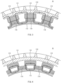
- FIG. 3 and FIG. 4 are partial sectional views (transverse sectional views) of the deceleration device main body 11 cut in a plane that is perpendicular to the shaft center X of the propeller shaft 21.
- the case 112 is omitted.
- FIG. 3 illustrates a braking state (brake on) of the deceleration device main body 11.
- FIG. 4 illustrates a non-braking state (brake off) of the deceleration device main body 11.
- the magnet holding member 113 holds the plurality of magnets 114 on the outer peripheral surface thereof.
- each magnet 114 is a permanent magnet.
- the plurality of permanent magnets 114 are arrayed in the circumferential direction at a predetermined spacing.
- the permanent magnets 114 are each arranged on the outer peripheral surface of the magnet holding member 113 to face toward the braking member 111 in the radial direction.
- each permanent magnet 114 is fixed to the magnet holding member 113 with an adhesive.
- Each permanent magnet 114 has a pair of magnetic poles (N-pole, S-pole).
- the orientation of the magnetic poles of each permanent magnet 114 is along the radial direction and is inverse with respect to the orientations of the magnetic poles of both neighboring permanent magnets 114. That is, each permanent magnet 114 has the N-pole or S-pole inward in the radial direction and has opposite S-pole or N-pole outward in the radial direction.
- Each pole piece 115 is made of a ferromagnetic material.
- the plurality of pole pieces 115 are arranged between the braking member 111 and the permanent magnets 114.
- the plurality of pole pieces 115 are arrayed in the circumferential direction at the same spacing as the permanent magnets 114.
- the permanent magnets 114 are each positioned immediately under the pole piece 115. Accordingly, magnetic fluxes (bold arrows) from each of the permanent magnets 114 pass through the pole piece 115 and reach the braking member 111 that rotates along with the propeller shaft 21 ( FIG. 2 ). This generates eddy currents in an inner circumferential surface of the braking member 111. Due to interaction between the eddy currents and magnetic fields generated by the permanent magnets 114, a braking force is generated in the braking member 111 in the direction opposite to the rotation direction. Furthermore, as the eddy currents are generated, Joule heat is generated in the braking member 111, causing the temperature of the braking member 111 and the permanent magnets 114 to rise.
- the magnet holding member 113 rotates to be positioned such that each permanent magnet 114 spans across adjacent pole pieces 115.
- a magnetic circuit is formed among the magnet holding member 113, the permanent magnets 114, and the pole pieces 115, so that the magnetic fluxes (bold arrows) from the permanent magnets 114 do not reach the braking member 111. Consequently, the braking force on the braking member 111 is cancelled.
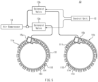
- FIG. 5 is a schematic diagram of components of the deceleration device 10. As illustrated in FIG. 5 , the deceleration device 10 further includes a control unit 12.
- the control unit 12 is a computer and includes a central processing unit (CPU) that executes a program, a memory that stores programs and data, and the like.
- the control unit 12 is formed from an electronic control unit (ECU) mounted on the vehicle 20 ( FIG. 1 ).
- ECU electronice control unit
- the control unit 12 controls braking states of the deceleration device main bodies 11a and 11b. More specifically, the control unit 12 sends electric signals to solenoid valves 13a and 13b connected to the air compressor 14 to control the solenoid valves 13a and 13b to open and close. Compressed air from the air compressor 14 passes through the solenoid valves 13a and 13b and is supplied to air cylinders 15a and 15b connected to the respective magnet holding member 113 of the deceleration device main bodies 11a and 11b. Extension and retraction of the air cylinders 15a and 15b causes the magnet holding member 113 to rotate around the central axis thereof, which allows each of the deceleration device main bodies 11a and 11b to assume either the braking state ( FIG.
- the control unit 12 is configured to be able to switch among the first state, the second state, and the third state.
- first state both of the deceleration device main bodies 11a and 11b are in the braking states ( FIG. 3 ).
- the second state one of the deceleration device main bodies 11a and 11b is in the braking state ( FIG. 3 ), while the other is in the non-braking state ( FIG. 4 ).
- both of the deceleration device main bodies 11a and 11b are in the non-braking states ( FIG. 4 ), in which the deceleration device 10 exerts substantially no braking force.
- the control unit 12 controls the solenoid valve 13a and/or the solenoid valve 13b in response to the operation to perform switching among the first state, the second state, and third state.
- FIG. 6 is a graphical representation illustrating the relationship between the braking torque (braking force) and time in the first state.
- FIG. 7 is a graphical representation illustrating the relationship between the braking torque and time in the second state.
- the deceleration device 10 exerts the largest braking force.
- the deceleration device 10 exerts about a half of the braking force in the first state.
- the control unit 12 is preferably configured to be able to place the two deceleration device main bodies 11a and 11b into the braking states alternately and consecutively. That is, the control unit 12 can control the deceleration device main bodies 11a and 11b such that the second state in which the deceleration device main body 11a is in the braking state alternates with the second state in which the deceleration device main body 11b is in the braking state.
- FIG. 8 is a graphical representation illustrating the relationship between the braking torque and time when the deceleration device main bodies 11a and 11b are alternately placed in the braking state.
- the control unit 12 first actuates the deceleration device main body 11a into the braking state and place the deceleration device main body 11b into the non-braking state, only the deceleration device main body 11a exerts the braking force.
- the temperature of the braking member 111 and the permanent magnets 114 rises over time, and the braking force decreases.
- the control unit 12 switches the deceleration device main body 11a from the braking state to the non-braking state and actuates the deceleration device main body 11b to switch from the non-braking state to the braking state.
- the deceleration device main body 11b which has been in the non-braking state immediately before then, can exert a high braking force because the braking member 111 and the permanent magnets 114 are not hot.
- the deceleration device main body 11a which is now in the non-braking state, eddy currents and the associated Joule heat are not generated in the braking member 111. Accordingly, the braking member 111 is no longer heated and the deceleration device main body 11a is naturally cooled (air cooling).
- the control unit 12 places the deceleration device main body 11b into the non-braking state and actuates the deceleration device main body 11a again into the braking state.
- the deceleration device main body 11a can exert a high braking force again because it is cooled while in the non-braking state.
- the deceleration device main body 11b is now in the non-braking state and naturally cooled (air cooling) because the braking member 111 is no longer heated.
- the control unit 12 can automatically perform control of placing the deceleration device main bodies 11a and 11b into braking states alternately and consecutively ( FIG. 8 ). For example, once the control unit 12 places the deceleration device main body 11a or 11b into the braking state and a predetermined time has passed, the control unit 12 may switch the deceleration device main body that is now in the braking state into the non-braking state and switch the deceleration device main body that is now in the non-braking state into the braking state among the deceleration device main bodies 11a and 11b.
- control unit 12 may detect the temperature of the deceleration device main bodies 11a and 11b with a well-known temperature sensor, and when a detected temperature is at or above a predetermined temperature, switch the deceleration device main body that is now in the braking state into the non-braking state and switch the deceleration device main body that is now in the non-braking state into the braking state among the deceleration device main bodies 11a and 11b. Furthermore, for example, according to a continuous braking time previously set in the control unit 12, the control unit 12 may switch between the braking state and the non-braking state of the deceleration device main bodies 11a and 11b.
- the control unit 12 can determine the alternation between the deceleration device main body 11a and the deceleration device main body 11b depending on the states of the deceleration device main bodies 11a and 11b or conditions previously set (stored) in the control unit 12 itself.
- the two deceleration device main bodies 11a and 11b are attached to the common propeller shaft 21. Accordingly, compared to the case in which a single deceleration device main body is attached to the propeller shaft 21, the braking force against rotation of the propeller shaft 21 and the vehicle 20 can be increased. For example, when both of the deceleration device main bodies 11a and 11b are in the braking states at the same time, it is possible to obtain a braking force about two times that in the case in which only one of the deceleration device main bodies 11a and 11b is placed into the braking state.
- the deceleration device 10 can be mounted in the vehicle 20 even in a limited space and satisfy the braking force required for the vehicle 20.
- the eddy current deceleration device 10 uses the deceleration device main bodies 11a and 11b to increase the braking force. With the deceleration device 10, it is not necessary to significantly alter the deceleration device main bodies 11a and 11b themselves from existing products for the purpose of increasing the braking force. Accordingly, it is possible to reduce time required for the development of the deceleration device main bodies 11a and 11b and rapidly provide the deceleration device 10 in response to a request or the like of consumers.
- the eddy current deceleration device 10 In the eddy current deceleration device 10 according to the embodiment, two-step switching between the braking state (brake on) and the non-braking state (brake off) is carried out for each of the deceleration device main bodies 11a and 11b, as in the conventional eddy current deceleration device. Accordingly, complex control of, for example, a mechanism (such as an air cylinder) for rotating the magnet holding member 113 is not needed. In the meantime, in the embodiment, the two deceleration device main bodies 11a and 11b are used, and therefore, braking forces can be switched in three steps for the overall deceleration device 10.
- a mechanism such as an air cylinder
- the control unit 12 is configured to be able to place the two deceleration device main bodies 11a and 11b into the braking states alternately and consecutively.
- the other of the deceleration device main bodies 11a and 11b can be placed in the non-braking state for cooling (being left to be cooled).
- the deceleration device main bodies 11a and 11b which experience a reduction in the braking force in a continuous braking state due to a temperature rise of the braking member 111 and the permanent magnets 114, can exert a high braking force again by being cooled.
- braking the vehicle 20 can be maintained for a long time by alternating braking states of the two deceleration device main bodies 11a and 11b.
- the deceleration device 10 can continue to exert the braking force suitable for such a travel for a long time.
- the eddy current deceleration device 10 includes the two deceleration device main bodies 11a and 11b. However, when there is a mounting space in the vehicle 20, the deceleration device 10 may include 3 or more deceleration device main bodies. Those deceleration device main bodies are attached to the common propeller shaft 21 in different positions as in the embodiment. The position of each deceleration device main body on the propeller shaft 21 is not particularly limited.
- the control unit 12 is formed from a single electronic control unit (ECU) and the braking states of the deceleration device main bodies 11a and 11b are controlled by a common electronic control unit.
- the control unit 12 may include a plurality of electronic control units. That is, an electronic control unit may be provided for each of the deceleration device main bodies 11a and 11b.
- an electronic control unit may be provided for each of the deceleration device main bodies 11a and 11b.
- a driver operation for the braking states of the deceleration device main bodies 11a and 11b may be complicated. Accordingly, it is preferable that the braking states of the deceleration device main bodies 11a and 11b are controlled by a common electronic control unit as in the embodiment.
- the deceleration device main bodies 11a and 11b each include the plurality of permanent magnets 114. That is, the deceleration device main bodies 11a and 11b are a permanent magnet type deceleration device. However, the deceleration device main bodies 11a and 11b may be an electromagnetic type deceleration device. The deceleration device main bodies 11a and 11b may include an electromagnet in place of the magnet holding member 113, the permanent magnets 114, the pole pieces 115, and the like.
Landscapes
- Engineering & Computer Science (AREA)
- Power Engineering (AREA)
- General Engineering & Computer Science (AREA)
- Mechanical Engineering (AREA)
- Transportation (AREA)
- Dynamo-Electric Clutches, Dynamo-Electric Brakes (AREA)
Abstract
Description
- The present disclosure relates to an eddy current deceleration device.
- Hitherto, eddy current deceleration devices have been used as auxiliary brakes for large vehicles such as trucks and buses. Patent Literature 1 discloses an eddy current deceleration device including a braking drum and a rotating yoke body. The braking drum is fixed to a propeller shaft of a vehicle, for example. The rotating yoke body includes a ring-shaped yoke and a plurality of permanent magnets. The plurality of permanent magnets are held on the outer peripheral surface of the yoke. A plurality of pole pieces are arranged between the braking drum and the plurality of permanent magnets.
- In Patent Literature 1, braking states of the eddy current deceleration device are controlled by a control unit in three steps. In response to operation by an operator on an operation unit, the control unit switches the deceleration device among a HIGH state in which the largest braking force is exerted, a LOW state in which the braking force is smaller than that in the HIGH state, and an OFF state in which no braking force is exerted. More specifically, upon the operation by the operator on the operation unit, the control unit controls a solenoid valve to adjust air supplied to an air cylinder. The rotating yoke body is rotated by extension and retraction of the air cylinder by a rotation angle corresponding to the operation. When the operator sets the HIGH state on the operation unit, the rotating yoke body is positioned such that each of the permanent magnets faces each of the pole pieces in their entire surface. When the operator sets the LOW state on the operation unit, the rotating yoke body is positioned such that only a half of each permanent magnet overlaps the pole piece. When the operator sets the OFF state on the operation unit, the rotating yoke body is positioned such that each permanent magnet spans across adjacent two pole pieces.
- Patent Literature 1: International Application Publication No.
WO2011/125542 - It is necessary for such an eddy current deceleration device to satisfy a braking force required for a vehicle. In order to increase the braking force of the eddy current deceleration device, the deceleration device main body must be made large, for example, for the purpose of increasing the number of magnets or increasing a relative speed (circumferential speed) between the braking drum and the magnet. However, when the eddy current deceleration device is to be mounted, for example, in a vehicle such as a small bus, for which it is difficult to secure a sufficient mounting space, the deceleration device main body cannot be increased in size due to constraints of mounting spaces, and the braking force required for the vehicle may not be satisfied.
- An objective of the present disclosure is to provide an eddy current deceleration device that can be mounted in a vehicle even in a limited space and can satisfy a braking force required for the vehicle.
- An eddy current deceleration device according to the present disclosure includes two deceleration device main bodies and a control unit. The two deceleration device main bodies each include a braking member that has a tubular shape and a magnet. The braking member is fixed to a propeller shaft. The magnet faces toward the braking member in a radial direction of the braking member. The control unit controls braking states of the two deceleration device main bodies. The two deceleration device main bodies are arranged in different positions in an axial direction of the propeller shaft.
- An eddy current deceleration device according to the present disclosure can be mounted in a vehicle even in a limited space and can satisfy a braking force required for the vehicle.
-
- [
FIG. 1] FIG. 1 is a schematic diagram illustrating a vehicle on which an eddy current deceleration device according to an embodiment is mounted. - [
FIG. 2] FIG. 2 is a longitudinal sectional view of a deceleration device main body included in the eddy current deceleration device according to the embodiment. - [
FIG. 3] FIG. 3 is a partial transverse sectional view of the deceleration device main body illustrated inFIG. 2 , illustrating a braking state of the deceleration device main body. - [
FIG. 4] FIG. 4 is a partial transverse sectional view of the deceleration device main body illustrated inFIG. 2 , illustrating a non-braking state of the deceleration device main body. - [
FIG. 5] FIG. 5 is a schematic diagram of components of the eddy current deceleration device according to the embodiment. - [
FIG. 6] FIG. 6 is a graphical representation illustrating the relationship between the braking torque and time in a first state for the eddy current deceleration device according to the embodiment. - [
FIG. 7] FIG. 7 is a graphical representation illustrating the relationship between the braking torque and time in a second state for the eddy current deceleration device according to the embodiment. - [
FIG. 8] FIG. 8 is a graphical representation illustrating the relationship between the braking torque and time when two deceleration device main bodies included in the eddy current deceleration device according to the embodiment are alternately placed in the braking state. - An eddy current deceleration device according to an embodiment includes two deceleration device main bodies and a control unit. The two deceleration device main bodies each include a braking member that has a tubular shape and a magnet. The braking member is fixed to a propeller shaft. The magnet faces toward the braking member in the radial direction of the braking member. The control unit controls braking states of the two deceleration device main bodies. The two deceleration device main bodies are arranged in different positions in the axial direction of the propeller shaft (first configuration).
- In the eddy current deceleration device according to the first configuration, the two deceleration device main bodies are attached to the common propeller shaft. Accordingly, compared to the case in which a single deceleration device main body is attached to a propeller shaft, the braking force against rotation of the propeller shaft can be increased. In this way, a high braking force can be secured for the overall eddy current deceleration device by the plurality of deceleration device main bodies, and therefore, it is not necessary to increase the size of an individual deceleration device main body. Accordingly, the eddy current deceleration device according to the first configuration can be mounted in a vehicle even in a limited space and satisfy the braking force required for the vehicle.
- The control unit may be configured to be able to switch among a first state, a second state, and a third state. In the first state, both of the two deceleration device main bodies are in braking states. In the second state, one deceleration device main body of the two deceleration device main bodies is in a braking state and the other deceleration device main body is in a non-braking state. In the third state, both of the two deceleration device main bodies are in non-braking states (second configuration).
- In the second configuration, the control unit switches the eddy current deceleration device among the first state, the second state, and the third state. In the first state, since both of the two deceleration device main bodies are in braking states, the eddy current deceleration device exerts a large braking force. In the second state, since one deceleration device main body is in a braking state and the other deceleration device main body is in a non-braking state, the eddy current deceleration device exerts a relatively small braking force. In the third state, since both of the two deceleration device main bodies are in non-braking states, the eddy current deceleration device exerts no braking force.
- In the second configuration, for example, choices can be made among the first state, the second state, and the third state depending on the running state of a vehicle. For example, when a vehicle on which the eddy current deceleration device is mounted is travelling on a steep slope downhill and a large braking force is needed, the control unit can place the eddy current deceleration device into the first state in which both of the two deceleration device main bodies are in braking states. In the meantime, for example, when a vehicle on which the eddy current deceleration device is mounted is travelling on a gentle slope downhill and a large braking force is not needed, the control unit can place the eddy current deceleration device into the second state in which only one of the two deceleration device main bodies is in a braking state. When no braking force is needed at all, the control unit can place the eddy current deceleration device into the third state in which both of the two deceleration device main bodies are in non-braking states.
- The control unit may be configured to be able to place the two deceleration device main bodies into braking states alternately and consecutively (third configuration).
- With a deceleration device main body being in a braking state, when the braking member rotates along with the propeller shaft in a magnetic field generated by the magnet, eddy currents are generated in the braking member. At this time, Joule heat is generated in the braking member and the temperature of the braking member rises. Due to radiant heat from the braking member, the temperature of the magnet facing toward the braking member may rise. Once the temperature of the braking member and the magnet rises, the braking force of the deceleration device main body decreases. Nevertheless, in the third configuration, the control unit is configured to be able to place the two deceleration device main bodies into braking states alternately and consecutively. In this case, while one deceleration device main body is in a braking state, the other deceleration device main body can be placed in a non-braking state for cooling. Once the deceleration device main body is in a braking state, the temperature of the braking member and the magnet increases and the braking force of the deceleration device main body decreases over time, while the deceleration device main body, once cooled, can exert a high braking force again. Accordingly, a predetermined braking force can be maintained for a long time by alternating braking states of the two deceleration device main bodies. For example, when a vehicle on which the eddy current deceleration device is mounted travels a long gentle slope downhill, the braking force suitable for such a travel can be exerted for a long time, according to the eddy current deceleration device according to the third configuration.
- Embodiments of the present disclosure will now be described with reference to drawings. In the drawings, the same or equivalent components will be denoted by the same reference numerals, and the description will not be repeated.
-
FIG. 1 is a schematic diagram illustrating avehicle 20 on which an eddycurrent deceleration device 10 according to the embodiment is mounted. For example, thedeceleration device 10 is used as an auxiliary brake of thevehicle 20.FIG. 1 illustrates an example in which thevehicle 20 is a small bus. However, thevehicle 20 may be any other vehicle than a small bus. - In the example illustrated in
FIG. 1 , thedeceleration device 10 is arranged at the rear of thevehicle 20. Thedeceleration device 10 is attached to apropeller shaft 21 of thevehicle 20. Thepropeller shaft 21 extends in the front-back direction of thevehicle 20. The front end portion of thepropeller shaft 21 is connected to a shaft of arear axle 22 through a final drive (not illustrated), for example. The rear end portion of thepropeller shaft 21 is connected to apower unit 23 including an engine, a crutch, a transmission, and the like, for example. For example, the rear end portion of thepropeller shaft 21 is connected to an output shaft (not illustrated) of the transmission. Thepropeller shaft 21 rotates around the shaft center thereof along with the output shaft of the transmission. - The
deceleration device 10 includes two deceleration devicemain bodies main bodies propeller shaft 21. In the embodiment, one deceleration devicemain body 11a is arranged adjacent to therear axle 22. The other deceleration devicemain body 11b is arranged adjacent to thepower unit 23. The deceleration devicemain body 11a is arranged in front of the deceleration devicemain body 11b. - In the embodiment, the deceleration device
main bodies main bodies main body 11 when it is not particularly necessary to distinguish them from one another. -
FIG. 2 is a longitudinal sectional view of the deceleration devicemain body 11. The longitudinal section refers to a section of the deceleration devicemain body 11 cut in a plane that includes the shaft center X of thepropeller shaft 21 to which the deceleration devicemain body 11 is attached. Hereinafter, the direction in which the shaft center X extends is referred to as an axial direction, and the circumferential direction and the radial direction of a circle centered on the shaft center X are referred to simply as a circumferential direction and a radial direction. - With reference to
FIG. 2 , the deceleration devicemain body 11 includes a braking member (rotor) 111, acase 112, amagnet holding member 113, a plurality ofmagnets 114, and a plurality ofpole pieces 115. The brakingmember 111 rotates around the shaft center X along with thepropeller shaft 21. Thecase 112 is fixed to a non-rotating part of the vehicle 20 (FIG. 1 ) so that thecase 112 does not rotate along with thepropeller shaft 21. Thecase 112 of one deceleration devicemain body 11a (FIG. 1 ) is fixed to, for example, a housing of the rear axle 22 (FIG. 1 ). Thecase 112 of the other deceleration devicemain body 11b (FIG. 1 ) is fixed to, for example, a cover of the transmission of the power unit 23 (FIG. 1 ). Themagnet holding member 113 and the plurality ofmagnets 114 are arranged within thecase 112. - The braking
member 111 is made of a conductive material. The brakingmember 111 has a tubular shape. The brakingmember 111 has typically a cylindrical shape with the shaft center X of thepropeller shaft 21 as the central axis. The brakingmember 111 is fixed to thepropeller shaft 21. The brakingmember 111 is fixed to thepropeller shaft 21 via ahub 116, aspoke 117, and the like. A plurality offins 118 are formed on the outer peripheral surface of thebraking member 111. - The
case 112 is arranged inside the brakingmember 111 in the radial direction. Thecase 112 is arranged concentrically with the brakingmember 111. Thecase 112 is attached to a non-rotating part of the vehicle 20 (FIG. 1 ) via asupport member 119. Themagnet holding member 113, the plurality ofmagnets 114, and the plurality ofpole pieces 115 are housed in thecase 112. - The
magnet holding member 113 is made of a ferromagnetic material. Themagnet holding member 113 has a tubular shape. Themagnet holding member 113 has typically a cylindrical shape with the shaft center X of thepropeller shaft 21 as the central axis. Themagnet holding member 113 is arranged substantially concentrically with the brakingmember 111. For example, themagnet holding member 113 is attached to thecase 112 via a ring-shaped slide plate (not illustrated) such that themagnet holding member 113 is slidable in the circumferential direction with respect to thecase 112. A braking state and a non-braking state are switched for the deceleration devicemain body 11 by rotating themagnet holding member 113 around thepropeller shaft 21. -
FIG. 3 and FIG. 4 are partial sectional views (transverse sectional views) of the deceleration devicemain body 11 cut in a plane that is perpendicular to the shaft center X of thepropeller shaft 21. InFIG. 3 and FIG. 4 , thecase 112 is omitted.FIG. 3 illustrates a braking state (brake on) of the deceleration devicemain body 11.FIG. 4 illustrates a non-braking state (brake off) of the deceleration devicemain body 11. - As illustrated in
FIG. 3 , themagnet holding member 113 holds the plurality ofmagnets 114 on the outer peripheral surface thereof. In the embodiment, eachmagnet 114 is a permanent magnet. The plurality ofpermanent magnets 114 are arrayed in the circumferential direction at a predetermined spacing. Thepermanent magnets 114 are each arranged on the outer peripheral surface of themagnet holding member 113 to face toward the brakingmember 111 in the radial direction. For example, eachpermanent magnet 114 is fixed to themagnet holding member 113 with an adhesive. - Each
permanent magnet 114 has a pair of magnetic poles (N-pole, S-pole). The orientation of the magnetic poles of eachpermanent magnet 114 is along the radial direction and is inverse with respect to the orientations of the magnetic poles of both neighboringpermanent magnets 114. That is, eachpermanent magnet 114 has the N-pole or S-pole inward in the radial direction and has opposite S-pole or N-pole outward in the radial direction. - Each
pole piece 115 is made of a ferromagnetic material. The plurality ofpole pieces 115 are arranged between the brakingmember 111 and thepermanent magnets 114. For example, the plurality ofpole pieces 115 are arrayed in the circumferential direction at the same spacing as thepermanent magnets 114. - Continuing with
FIG. 3 , when the deceleration devicemain body 11 is in a braking state, thepermanent magnets 114 are each positioned immediately under thepole piece 115. Accordingly, magnetic fluxes (bold arrows) from each of thepermanent magnets 114 pass through thepole piece 115 and reach thebraking member 111 that rotates along with the propeller shaft 21 (FIG. 2 ). This generates eddy currents in an inner circumferential surface of thebraking member 111. Due to interaction between the eddy currents and magnetic fields generated by thepermanent magnets 114, a braking force is generated in thebraking member 111 in the direction opposite to the rotation direction. Furthermore, as the eddy currents are generated, Joule heat is generated in thebraking member 111, causing the temperature of thebraking member 111 and thepermanent magnets 114 to rise. - With reference to
FIG. 4 , when the deceleration devicemain body 11 is switched from the braking state to a non-braking state, themagnet holding member 113 rotates to be positioned such that eachpermanent magnet 114 spans acrossadjacent pole pieces 115. In the non-braking state, a magnetic circuit is formed among themagnet holding member 113, thepermanent magnets 114, and thepole pieces 115, so that the magnetic fluxes (bold arrows) from thepermanent magnets 114 do not reach thebraking member 111. Consequently, the braking force on thebraking member 111 is cancelled. -
FIG. 5 is a schematic diagram of components of thedeceleration device 10. As illustrated inFIG. 5 , thedeceleration device 10 further includes acontrol unit 12. Thecontrol unit 12 is a computer and includes a central processing unit (CPU) that executes a program, a memory that stores programs and data, and the like. Typically, thecontrol unit 12 is formed from an electronic control unit (ECU) mounted on the vehicle 20 (FIG. 1 ). - The
control unit 12 controls braking states of the deceleration devicemain bodies control unit 12 sends electric signals tosolenoid valves air compressor 14 to control thesolenoid valves air compressor 14 passes through thesolenoid valves air cylinders magnet holding member 113 of the deceleration devicemain bodies air cylinders magnet holding member 113 to rotate around the central axis thereof, which allows each of the deceleration devicemain bodies FIG. 3 ) or the non-braking state (FIG. 4 ). The operation of thesolenoid valves air compressor 14, and theair cylinders - The
control unit 12 is configured to be able to switch among the first state, the second state, and the third state. In the first state, both of the deceleration devicemain bodies FIG. 3 ). In the second state, one of the deceleration devicemain bodies FIG. 3 ), while the other is in the non-braking state (FIG. 4 ). In the third state, both of the deceleration devicemain bodies FIG. 4 ), in which thedeceleration device 10 exerts substantially no braking force. For example, when a driver operates an operation unit provided to the vehicle 20 (FIG. 1 ), thecontrol unit 12 controls thesolenoid valve 13a and/or thesolenoid valve 13b in response to the operation to perform switching among the first state, the second state, and third state. -
FIG. 6 is a graphical representation illustrating the relationship between the braking torque (braking force) and time in the first state.FIG. 7 is a graphical representation illustrating the relationship between the braking torque and time in the second state. As illustrated inFIG. 6 , since both of the deceleration devicemain bodies deceleration device 10 exerts the largest braking force. As illustrated inFIG. 7 , since only one of the deceleration devicemain bodies deceleration device 10 exerts about a half of the braking force in the first state. - The
control unit 12 is preferably configured to be able to place the two deceleration devicemain bodies control unit 12 can control the deceleration devicemain bodies main body 11a is in the braking state alternates with the second state in which the deceleration devicemain body 11b is in the braking state. -
FIG. 8 is a graphical representation illustrating the relationship between the braking torque and time when the deceleration devicemain bodies FIG. 8 , when thecontrol unit 12 first actuates the deceleration devicemain body 11a into the braking state and place the deceleration devicemain body 11b into the non-braking state, only the deceleration devicemain body 11a exerts the braking force. In the deceleration devicemain body 11a, the temperature of thebraking member 111 and thepermanent magnets 114 rises over time, and the braking force decreases. Once the braking force of the deceleration devicemain body 11a decreases, thecontrol unit 12 switches the deceleration devicemain body 11a from the braking state to the non-braking state and actuates the deceleration devicemain body 11b to switch from the non-braking state to the braking state. The deceleration devicemain body 11b, which has been in the non-braking state immediately before then, can exert a high braking force because thebraking member 111 and thepermanent magnets 114 are not hot. On the other hand, in the deceleration devicemain body 11a, which is now in the non-braking state, eddy currents and the associated Joule heat are not generated in thebraking member 111. Accordingly, the brakingmember 111 is no longer heated and the deceleration devicemain body 11a is naturally cooled (air cooling). - In the deceleration device
main body 11b in the braking state, the temperature of thebraking member 111 and thepermanent magnets 114 rises over time, and the braking force decreases. Once the braking force of the deceleration devicemain body 11b decreases, thecontrol unit 12 places the deceleration devicemain body 11b into the non-braking state and actuates the deceleration devicemain body 11a again into the braking state. The deceleration devicemain body 11a can exert a high braking force again because it is cooled while in the non-braking state. On the other hand, the deceleration devicemain body 11b is now in the non-braking state and naturally cooled (air cooling) because thebraking member 111 is no longer heated. - When the second state is selected by a driver operation, for example, the
control unit 12 can automatically perform control of placing the deceleration devicemain bodies FIG. 8 ). For example, once thecontrol unit 12 places the deceleration devicemain body control unit 12 may switch the deceleration device main body that is now in the braking state into the non-braking state and switch the deceleration device main body that is now in the non-braking state into the braking state among the deceleration devicemain bodies control unit 12 may detect the temperature of the deceleration devicemain bodies main bodies control unit 12, thecontrol unit 12 may switch between the braking state and the non-braking state of the deceleration devicemain bodies control unit 12 can determine the alternation between the deceleration devicemain body 11a and the deceleration devicemain body 11b depending on the states of the deceleration devicemain bodies control unit 12 itself. - In the eddy
current deceleration device 10 according to the embodiment, the two deceleration devicemain bodies common propeller shaft 21. Accordingly, compared to the case in which a single deceleration device main body is attached to thepropeller shaft 21, the braking force against rotation of thepropeller shaft 21 and thevehicle 20 can be increased. For example, when both of the deceleration devicemain bodies main bodies overall deceleration device 10 by the deceleration devicemain bodies main bodies deceleration device 10 can be mounted in thevehicle 20 even in a limited space and satisfy the braking force required for thevehicle 20. - The eddy
current deceleration device 10 according to the embodiment uses the deceleration devicemain bodies deceleration device 10, it is not necessary to significantly alter the deceleration devicemain bodies main bodies deceleration device 10 in response to a request or the like of consumers. - According to the eddy
current deceleration device 10 according to the embodiment, choices can be made among the first state, the second state, and the third state depending on the running state of the vehicle, and the like. For example, when thevehicle 20 is travelling on a steep slope downhill and a large braking force is needed, thecontrol unit 12 can place thedeceleration device 10 into the first state to exert the largest braking force. In the meantime, for example, when thevehicle 20 is travelling on a gentle slope downhill and a large braking force is not needed, thecontrol unit 12 can place thedeceleration device 10 into the second state to obtain a relatively small braking force. When no braking force is needed at all, thecontrol unit 12 may place thedeceleration device 10 into the third state. - In the eddy
current deceleration device 10 according to the embodiment, two-step switching between the braking state (brake on) and the non-braking state (brake off) is carried out for each of the deceleration devicemain bodies magnet holding member 113 is not needed. In the meantime, in the embodiment, the two deceleration devicemain bodies overall deceleration device 10. In thedeceleration device 10 according to the embodiment, the first state in which the deceleration devicemain bodies main bodies main bodies deceleration device 10. - In the eddy
current deceleration device 10 according to the embodiment, thecontrol unit 12 is configured to be able to place the two deceleration devicemain bodies main bodies main bodies main bodies braking member 111 and thepermanent magnets 114, can exert a high braking force again by being cooled. Accordingly, braking thevehicle 20 can be maintained for a long time by alternating braking states of the two deceleration devicemain bodies vehicle 20 travels a long gentle slope downhill, thedeceleration device 10 can continue to exert the braking force suitable for such a travel for a long time. - Although the embodiment according to the present disclosure has been described, the present disclosure is not limited to the embodiment and various modifications can be made thereto without departing from the spirt thereof.
- The eddy
current deceleration device 10 according to the embodiment includes the two deceleration devicemain bodies vehicle 20, thedeceleration device 10 may include 3 or more deceleration device main bodies. Those deceleration device main bodies are attached to thecommon propeller shaft 21 in different positions as in the embodiment. The position of each deceleration device main body on thepropeller shaft 21 is not particularly limited. - In the embodiment, for example, the
control unit 12 is formed from a single electronic control unit (ECU) and the braking states of the deceleration devicemain bodies control unit 12 may include a plurality of electronic control units. That is, an electronic control unit may be provided for each of the deceleration devicemain bodies main bodies main bodies main bodies - In the embodiment, the deceleration device
main bodies permanent magnets 114. That is, the deceleration devicemain bodies main bodies main bodies magnet holding member 113, thepermanent magnets 114, thepole pieces 115, and the like. -
- 10: eddy current deceleration device
- 11, 11a, 11b: deceleration device main body
- 111: braking member
- 114: magnet
- 12: control unit
- 21: propeller shaft
Claims (3)
- An eddy current deceleration device comprising:two deceleration device main bodies each including: a braking member that is fixed to a propeller shaft and has a tubular shape; and a magnet facing toward the braking member in a radial direction of the braking member; anda control unit that controls braking states of the two deceleration device main bodies, whereinthe two deceleration device main bodies are arranged in different positions in an axial direction of the propeller shaft.
- The eddy current deceleration device according to claim 1, wherein
the control unit configured to be able to switch among:a first state in which both of the two deceleration device main bodies are in braking states;a second state in which one deceleration device main body of the two deceleration device main bodies is in a braking state and the other deceleration device main body is in a non-braking state; anda third state in which both of the two deceleration device main bodies are in non-braking states. - The eddy current deceleration device according to claim 1 or 2, wherein
the control unit is configured to be able to place the two deceleration device main bodies into braking states alternately and consecutively.
Applications Claiming Priority (1)
| Application Number | Priority Date | Filing Date | Title |
|---|---|---|---|
| PCT/JP2022/018321 WO2023203693A1 (en) | 2022-04-20 | 2022-04-20 | Eddy current-type speed reducer |
Publications (2)
| Publication Number | Publication Date |
|---|---|
| EP4513050A1 true EP4513050A1 (en) | 2025-02-26 |
| EP4513050A4 EP4513050A4 (en) | 2025-06-18 |
Family
ID=88419499
Family Applications (1)
| Application Number | Title | Priority Date | Filing Date |
|---|---|---|---|
| EP22938493.8A Pending EP4513050A4 (en) | 2022-04-20 | 2022-04-20 | EDDY CURRENT TYPE SPEED REDUCER |
Country Status (6)
| Country | Link |
|---|---|
| US (1) | US20250249753A1 (en) |
| EP (1) | EP4513050A4 (en) |
| JP (1) | JPWO2023203693A1 (en) |
| KR (1) | KR20250003773A (en) |
| CN (1) | CN119032227A (en) |
| WO (1) | WO2023203693A1 (en) |
Family Cites Families (13)
| Publication number | Priority date | Publication date | Assignee | Title |
|---|---|---|---|---|
| JPS4815024Y1 (en) * | 1970-02-27 | 1973-04-25 | ||
| JP2795006B2 (en) * | 1991-10-18 | 1998-09-10 | 日産自動車株式会社 | Energy regeneration device |
| JPH0734235U (en) * | 1993-12-02 | 1995-06-23 | 東洋運搬機株式会社 | Auxiliary braking system for industrial vehicles |
| JP2006271186A (en) * | 2004-12-13 | 2006-10-05 | Kazuichi Seki | Wind turbine generator over-rotation prevention device |
| CN101359865B (en) * | 2008-09-19 | 2010-06-09 | 北京工业大学 | A scalable liquid-cooled permanent magnet retarder |
| JP5606768B2 (en) * | 2010-04-07 | 2014-10-15 | 日野自動車株式会社 | Retarder control device, retarder control method, and vehicle having retarder control device |
| DE102013203431A1 (en) * | 2013-02-28 | 2014-08-28 | Zf Friedrichshafen Ag | Rotary damper for a vehicle |
| JP6009427B2 (en) * | 2013-11-18 | 2016-10-19 | 東芝三菱電機産業システム株式会社 | Electric motor with brake |
| EP3109985B1 (en) * | 2014-02-17 | 2020-01-15 | Nippon Steel Corporation | Eddy current deceleration device equipped with power generation function |
| US10756612B2 (en) * | 2015-06-12 | 2020-08-25 | Nippon Steel & Sumitomo Metal Corporation | Eddy current deceleration device |
| CN106059250B (en) * | 2016-06-01 | 2019-02-05 | 清研瑞能(天津)科技有限公司 | A rotor-embedded electromagnetic liquid-cooled retarder |
| US11165326B2 (en) * | 2018-01-29 | 2021-11-02 | Nippon Steel Corporation | Eddy current decelerating apparatus |
| JP7372539B2 (en) * | 2020-01-10 | 2023-11-01 | 日本製鉄株式会社 | Eddy current reduction gear |
-
2022
- 2022-04-20 JP JP2024515979A patent/JPWO2023203693A1/ja active Pending
- 2022-04-20 KR KR1020247037482A patent/KR20250003773A/en active Pending
- 2022-04-20 WO PCT/JP2022/018321 patent/WO2023203693A1/en not_active Ceased
- 2022-04-20 US US18/853,193 patent/US20250249753A1/en active Pending
- 2022-04-20 CN CN202280094975.8A patent/CN119032227A/en active Pending
- 2022-04-20 EP EP22938493.8A patent/EP4513050A4/en active Pending
Also Published As
| Publication number | Publication date |
|---|---|
| US20250249753A1 (en) | 2025-08-07 |
| CN119032227A (en) | 2024-11-26 |
| WO2023203693A1 (en) | 2023-10-26 |
| JPWO2023203693A1 (en) | 2023-10-26 |
| EP4513050A4 (en) | 2025-06-18 |
| KR20250003773A (en) | 2025-01-07 |
Similar Documents
| Publication | Publication Date | Title |
|---|---|---|
| US10788090B2 (en) | Automobile having disc type hub motor | |
| US11404950B2 (en) | Retarder-equipped rotating electrical machine | |
| US5143183A (en) | Eddy current braking system | |
| US12542474B2 (en) | Eddy current magnetic braking device, braked vehicle wheel and aircraft landing gear equipped with such a wheel | |
| US20250249753A1 (en) | Eddy current deceleration device | |
| US5855256A (en) | Guide frame for eddy current type breaking system | |
| CN109969149B (en) | Disc brake, control system thereof and vehicle | |
| JP3765291B2 (en) | Eddy current reducer | |
| KR101575280B1 (en) | Brake system for vehicle and control method | |
| JP2004215430A (en) | Eddy current type reduction gear | |
| JPH0386061A (en) | Eddy current type reduction gear | |
| CN213007370U (en) | Novel magnetic suspension tire and automobile | |
| JP3791447B2 (en) | Compact and lightweight eddy current reducer | |
| JP2004173474A (en) | Eddy current type reduction gear | |
| JP3721991B2 (en) | Braking force control method for eddy current type speed reducer | |
| JP3882488B2 (en) | Eddy current reducer | |
| JP3484992B2 (en) | Eddy current speed reducer | |
| JP3985632B2 (en) | Eddy current reducer | |
| JP2002112528A (en) | Eddy current reducer | |
| JP2757683B2 (en) | Windage reduction device of eddy current type reduction gear | |
| JP3285052B2 (en) | Eddy current type reduction gear | |
| JP4374934B2 (en) | Eddy current reducer | |
| JP2009232528A (en) | Eddy-current braking device | |
| KR101585666B1 (en) | Eddy current braking device | |
| JP2003274634A (en) | Eddy current reducer |
Legal Events
| Date | Code | Title | Description |
|---|---|---|---|
| STAA | Information on the status of an ep patent application or granted ep patent |
Free format text: STATUS: THE INTERNATIONAL PUBLICATION HAS BEEN MADE |
|
| PUAI | Public reference made under article 153(3) epc to a published international application that has entered the european phase |
Free format text: ORIGINAL CODE: 0009012 |
|
| STAA | Information on the status of an ep patent application or granted ep patent |
Free format text: STATUS: REQUEST FOR EXAMINATION WAS MADE |
|
| 17P | Request for examination filed |
Effective date: 20240918 |
|
| AK | Designated contracting states |
Kind code of ref document: A1 Designated state(s): AL AT BE BG CH CY CZ DE DK EE ES FI FR GB GR HR HU IE IS IT LI LT LU LV MC MK MT NL NO PL PT RO RS SE SI SK SM TR |
|
| A4 | Supplementary search report drawn up and despatched |
Effective date: 20250520 |
|
| RIC1 | Information provided on ipc code assigned before grant |
Ipc: H02K 49/04 20060101ALI20250514BHEP Ipc: B60L 7/28 20060101ALI20250514BHEP Ipc: H02K 49/02 20060101ALI20250514BHEP Ipc: F16D 63/00 20060101AFI20250514BHEP |
|
| DAV | Request for validation of the european patent (deleted) | ||
| DAX | Request for extension of the european patent (deleted) |