EP4513048A1 - Roller bearing - Google Patents
Roller bearing Download PDFInfo
- Publication number
- EP4513048A1 EP4513048A1 EP23791809.9A EP23791809A EP4513048A1 EP 4513048 A1 EP4513048 A1 EP 4513048A1 EP 23791809 A EP23791809 A EP 23791809A EP 4513048 A1 EP4513048 A1 EP 4513048A1
- Authority
- EP
- European Patent Office
- Prior art keywords
- axial direction
- inner ring
- recess
- base
- flange member
- Prior art date
- Legal status (The legal status is an assumption and is not a legal conclusion. Google has not performed a legal analysis and makes no representation as to the accuracy of the status listed.)
- Pending
Links
Images



Classifications
-
- F—MECHANICAL ENGINEERING; LIGHTING; HEATING; WEAPONS; BLASTING
- F16—ENGINEERING ELEMENTS AND UNITS; GENERAL MEASURES FOR PRODUCING AND MAINTAINING EFFECTIVE FUNCTIONING OF MACHINES OR INSTALLATIONS; THERMAL INSULATION IN GENERAL
- F16C—SHAFTS; FLEXIBLE SHAFTS; ELEMENTS OR CRANKSHAFT MECHANISMS; ROTARY BODIES OTHER THAN GEARING ELEMENTS; BEARINGS
- F16C33/00—Parts of bearings; Special methods for making bearings or parts thereof
- F16C33/30—Parts of ball or roller bearings
- F16C33/58—Raceways; Race rings
- F16C33/60—Raceways; Race rings divided or split, e.g. comprising two juxtaposed rings
- F16C33/605—Raceways; Race rings divided or split, e.g. comprising two juxtaposed rings with a separate retaining member, e.g. flange, shoulder, guide ring, secured to a race ring, adjacent to the race surface, so as to abut the end of the rolling elements, e.g. rollers, or the cage
-
- F—MECHANICAL ENGINEERING; LIGHTING; HEATING; WEAPONS; BLASTING
- F16—ENGINEERING ELEMENTS AND UNITS; GENERAL MEASURES FOR PRODUCING AND MAINTAINING EFFECTIVE FUNCTIONING OF MACHINES OR INSTALLATIONS; THERMAL INSULATION IN GENERAL
- F16C—SHAFTS; FLEXIBLE SHAFTS; ELEMENTS OR CRANKSHAFT MECHANISMS; ROTARY BODIES OTHER THAN GEARING ELEMENTS; BEARINGS
- F16C19/00—Bearings with rolling contact, for exclusively rotary movement
- F16C19/22—Bearings with rolling contact, for exclusively rotary movement with bearing rollers essentially of the same size in one or more circular rows, e.g. needle bearings
- F16C19/34—Bearings with rolling contact, for exclusively rotary movement with bearing rollers essentially of the same size in one or more circular rows, e.g. needle bearings for both radial and axial load
- F16C19/36—Bearings with rolling contact, for exclusively rotary movement with bearing rollers essentially of the same size in one or more circular rows, e.g. needle bearings for both radial and axial load with a single row of rollers
- F16C19/364—Bearings with rolling contact, for exclusively rotary movement with bearing rollers essentially of the same size in one or more circular rows, e.g. needle bearings for both radial and axial load with a single row of rollers with tapered rollers, i.e. rollers having essentially the shape of a truncated cone
-
- F—MECHANICAL ENGINEERING; LIGHTING; HEATING; WEAPONS; BLASTING
- F16—ENGINEERING ELEMENTS AND UNITS; GENERAL MEASURES FOR PRODUCING AND MAINTAINING EFFECTIVE FUNCTIONING OF MACHINES OR INSTALLATIONS; THERMAL INSULATION IN GENERAL
- F16C—SHAFTS; FLEXIBLE SHAFTS; ELEMENTS OR CRANKSHAFT MECHANISMS; ROTARY BODIES OTHER THAN GEARING ELEMENTS; BEARINGS
- F16C2226/00—Joining parts; Fastening; Assembling or mounting parts
- F16C2226/50—Positive connections
- F16C2226/52—Positive connections with plastic deformation, e.g. caulking or staking
-
- F—MECHANICAL ENGINEERING; LIGHTING; HEATING; WEAPONS; BLASTING
- F16—ENGINEERING ELEMENTS AND UNITS; GENERAL MEASURES FOR PRODUCING AND MAINTAINING EFFECTIVE FUNCTIONING OF MACHINES OR INSTALLATIONS; THERMAL INSULATION IN GENERAL
- F16C—SHAFTS; FLEXIBLE SHAFTS; ELEMENTS OR CRANKSHAFT MECHANISMS; ROTARY BODIES OTHER THAN GEARING ELEMENTS; BEARINGS
- F16C2226/00—Joining parts; Fastening; Assembling or mounting parts
- F16C2226/50—Positive connections
- F16C2226/60—Positive connections with threaded parts, e.g. bolt and nut connections
Definitions
- the present invention relates to a roller bearing.
- a conical roller bearing described in Patent Literature 1 includes an inner ring having an inner ring raceway surface, an outer ring having an outer ring raceway surface, a plurality of conical rollers serving as rolling bodies that roll between the inner ring raceway surface and the outer ring raceway surface, and a cage for retaining the conical rollers at an equal interval in a circumferential direction.
- a large flange is formed integrally with a large-diameter side end of the inner ring, and a small flange member which is a separate body and prevents the conical rollers from falling off is provided at a small-diameter side end of the inner ring.
- the small flange member is locked to the inner ring by bolts. Accordingly, when the inside of the conical roller bearing is inspected or the cage is replaced, the conical roller bearing can be disassembled by removing the small flange member.
- Patent Literature 1 JP2014-190352A
- the present invention has been made in view of the above circumstances, and an object thereof is to provide a roller bearing capable of preventing a fastening member for fastening a flange member to an inner ring from falling off.
- roller bearing capable of preventing a fastening member for fastening a flange member to an inner ring from falling off.
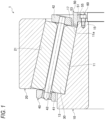
- Fig. 1 is a sectional view of a conical roller bearing 1 according to a first embodiment of the present invention.
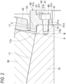
- Fig. 2 is a sectional view of a main part of the conical roller bearing 1 in Fig. 1 .
- the conical roller bearing 1 includes an inner ring 10 including an outer peripheral surface having a conical inner ring raceway surface 11, an outer ring 20 including an inner peripheral surface having a conical outer ring raceway surface 21, and a plurality of conical rollers 30 disposed such that the conical rollers are capable of rolling between the inner ring raceway surface 11 and the outer ring raceway surface 21.
- the conical rollers 30 are held at a constant interval in a circumferential direction by an annular cage 40 incorporated between the inner ring raceway surface 11 and the outer ring raceway surface 21.
- the cage 40 is a pin-type cage and includes a pair of annular portions 41 and 42 and a pin 43 for fastening the pair of annular portions 41 and 42.
- the type of the cage 40 is not limited, and for example, a press cage (basket cage) made of a steel plate may be used, which includes a large-diameter ring, a small-diameter ring, a plurality of pillars that couple the large-diameter ring and the small-diameter ring in an axial direction, and a pocket that is defined between the large-diameter ring and the pillars adjacent to the small-diameter ring.
- a press cage basic cage
- One end of the inner ring 10 in an axial direction (the left end in the drawing, a large-diameter side end) is formed with a flange 13 integrated with the inner ring 10.
- the flange 13 protrudes from the inner ring raceway surface 11 toward a radially outer side, and prevents the conical rollers 30 from falling off to one end side in the axial direction.
- the flange 13 constitutes a large flange of the inner ring 10.
- the other end of the inner ring 10 in the axial direction (the right end in the drawing, a small-diameter side end) is formed with an inner ring boss 15 protruding from the inner ring raceway surface 11 toward the other end side in the axial direction.
- Fig. 2 shows a virtual plane A perpendicular to the inner ring raceway surface 11 extending from the other end 11a of the inner ring raceway surface 11 in the axial direction, and a virtual plane B extending in a radial direction from the other end 11a in the axial direction.
- the inner ring boss 15 protrudes from the virtual planes A and B toward the other end side in the axial direction.
- the inner ring boss 15 is a projection protruding from a position separated from the other end 11a of the inner ring raceway surface 11 in the axial direction to a radially inner side toward the other end side in the axial direction, and therefore, a stepped portion 17 is formed between the inner ring boss 15 and the other end 11a of the inner ring raceway surface 11 in the axial direction.
- the bolt 60 in the present embodiment is a hexagon socket head bolt, the type of the bolt is not particularly limited, and it is needless to say that other types of fastening members such as screws may be used. Since the fastening member such as the bolt 60 extend in the axial direction and fasten the inner ring boss 15 and the flange member 50 in the axial direction, the bolts can be easily fastened regardless of the form of the cage. Since the attachment and detachment of the flange member 50 can be easily performed, assembly work of the conical roller bearing 1 becomes easy, and inspection of the inside of the conical roller bearing 1 and replacement of the conical rollers 30 or the cage 40 become easy.
- a threaded hole 15a directed in the axial direction is formed in the inner ring boss 15.
- a female thread portion of the threaded hole 15a is preferably formed so as not to overlap the virtual plane A in the axial direction, and more specifically, the female thread portion of the threaded hole 15a is preferably disposed on the other end side in the axial direction with respect to the virtual plane A.
- the bolt 60 screwed into the female thread portion of the threaded hole 15a is also disposed so as not to overlap the virtual plane A in the axial direction, and more specifically, is disposed on the other end side in the axial direction with respect to the virtual plane A.
- the female thread portion of the threaded hole 15a of the inner ring boss 15 is formed so as not to overlap the other end 11a (virtual plane B) of the inner ring raceway surface 11 in the axial direction, and more specifically, is disposed on the other end side in the axial direction of the other end 11a (virtual plane B) of the inner ring raceway surface 11 in the axial direction.
- the bolt 60 screwed into the female thread portion of the threaded hole 15a is also disposed so as not to overlap the other end 11a (virtual plane B) of the inner ring raceway surface 11 in the axial direction, and more specifically, is disposed on the other end side in the axial direction of the other end 11a (virtual plane B) of the inner ring raceway surface 11 in the axial direction.
- the above description does not exclude a mode in which the bolt fastening portion overlaps the virtual planes A and B in the axial direction.
- the flange member 50 may be configured by an annular member, or may be configured by arranging a plurality of circular ring pieces forming a part of a circular ring at intervals in the circumferential direction.
- the flange member 50 includes an annular base 51 extending to a radially outer side of the inner ring boss 15, and a projection 53 protruding from an end on the radially outer side of the base 51 toward one side in the axial direction (a direction of an arrow E in Fig. 2 , a direction approaching the inner ring 10 and the conical rollers 30).
- the base 51 abuts against the inner ring boss 15 in the axial direction.
- the projection 53 enters the stepped portion 17 of the inner ring 10.
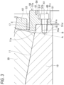
- Fig. 3 is a sectional view of a main part of the conical roller bearing 1 before a caulking portion 55, which will be described later, is formed.
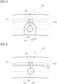
- Fig. 4 is a view of the flange member 50 before the caulking portion 55, which will be described later, is formed, as viewed from the other end side in the axial direction (the right side in Figs. 1 to 3 ).
- the base 51 includes a recess 51b recessed from the other end surface 51a in the axial direction toward one side in the axial direction.
- the recess 51b functions as a seating portion on which a head 61 of the bolt 60 is seated.
- an edge (peripheral wall) 51f of the recess 51b in the present embodiment has an inverted U shape as viewed in the axial direction, and opens to a radially inner side, but the shape of the recess 51b is not particularly limited.
- a through hole 51e penetrating from a bottom surface 51c (the other end surface in the axial direction) of the recess 51b to one end surface 51d of the base 51 in the axial direction is formed in the base 51.
- the through hole 51e is provided at a position facing the threaded hole 15a of the inner ring boss 15 in the axial direction. Accordingly, as in the illustrated embodiment, the through holes 51e and the recesses 51b in which the through holes 51e are respectively formed are provided in the same number as the threaded holes 15a.
- the bolt 60 passes through the through hole 51e of the base 51 and is screwed into the threaded hole 15a of the inner ring boss 15 to extend in the axial direction, thereby fastening the inner ring boss 15 and the flange member 50 in the axial direction.
- the head 61 of the bolt 60 is seated on the recess 51b of the base 51.
- the projection 53 of the flange member 50 fastened to the inner ring boss 15 is positioned on the radially outer side of the other end 11a in the axial direction of the inner ring raceway surface 11 and faces the conical rollers 30 in the axial direction, so as to prevent the conical rollers 30 from falling off to the other end side in the axial direction.
- the flange member 50 constitutes a small flange of the inner ring 10.
- the flange member 50 includes the caulking portion 55 that presses the head 61 of the bolt 60 from the other end side in the axial direction.
- the caulking portion 55 extends from at least a part of the edge 51f of the recess 51b so as to overlap the head 61 of the bolt 60.
- the caulking portion 55 in the embodiment shown in Fig. 2 extends from a radially outer side portion of the edge 51f of the recess 51b to the radially inner side and presses a radially outer side portion of the head 61 of the bolt 60 from the other end side in the axial direction.
- the caulking portion 55 is formed by plastically deforming a thin wall 59 shown in Figs. 3 to 4 with a tool or the like.
- the base 51 of the flange member 50 is formed with a groove 57 recessed from the other end surface 51a in the axial direction toward one side in the axial direction on a side opposite to the head 61 of the bolt 60 and the recess 51b with the caulking portion 55 interposed therebetween (on a radially outer side of the caulking portion 55 in the illustrated embodiment). That is, the groove 57 in the present embodiment is recessed at a position separated from the recess 51b on the radially outer side of the recess 51b. As shown in Fig. 4 , the groove 57 in the present embodiment is formed over the whole circumference of the base 51.
- the thin wall 59 is provided between the recess 51b and the groove 57 in a state before the caulking portion 55 is formed.
- a region surrounded by a broken line C in Fig. 4 is plastically deformed to the radially inner side by a tool such as a punch to obtain the caulking portion 55 as shown in Fig. 2 .
- the caulking portion 55 prevents the bolt 60 from falling off even when the bolt 60 is loosened.
- the groove 57 is not necessarily formed over the whole circumference of the base 51, and the position thereof is not limited as long as it is formed on the side opposite to the recess 51b with the caulking portion 55 (thin wall 59) interposed therebetween.
- the groove 57 may be intermittently provided only on the radially outer side of the recess 51b so as to be separated from the recess 51b.
- the groove 57 may be provided on at least one of both sides in the circumferential direction of the recess 51b.
- the thin wall 59 is provided between the groove 57 and the recess 51b, by plastically deforming the thin wall 59, it is possible to form the caulking portion 55 which extends from at least a part of the edge 51f of the recess 51b and overlaps the head 61 of the bolt 60.
- Fig. 5 is a view of the flange member 50 according to a modification before the caulking portion 55 is formed, as viewed from the other end side in the axial direction.
- a recess 51b is formed over the whole circumference of the base 51.
- the groove 57 is formed over the whole circumference of the base 51 in a manner of being separated from the recess 51b toward the radially outer side.
- the thin wall 59 is also provided between the recess 51b and the groove 57 over the whole circumference of the base 51.
- the thin wall 59 for example, a region surrounded by a broken line D in Fig.
- the conical roller bearing 1 according to a second embodiment is the same as that of the first embodiment except for the flange member 50, and therefore, same configurations are designated by same reference numerals in the drawings and descriptions thereof are omitted or simplified.
- Fig. 6 is a sectional view of the conical roller bearing 1 according to the second embodiment of the present invention.
- Fig. 7 is a sectional view of a main part of the conical roller bearing 1 in Fig. 6 .
- Fig. 8 is a view of the flange member 50 in Fig. 7 as viewed in a direction of an arrow IIX.
- Fig. 9 is a view of the flange member 50 in Fig. 7 as viewed in a direction of an arrow IX.
- Fig. 10 is a sectional view of a main part of the conical roller bearing 1 before the caulking portion 55 is formed.
- the base 51 includes a recess 51b recessed from the other end surface 51a in the axial direction toward one side in the axial direction.
- the recess 51b functions as a seating portion on which the head 61 of the bolt 60 is seated.
- the edge (peripheral wall) 51f of the recess 51b in the present embodiment has a circular shape as viewed in the axial direction, and has a shape closed in both the radial direction (the upper-lower direction in Figs. 7 and 8 ) and the circumferential direction (the left-right direction in Fig. 8 ).
- the through hole 51e penetrating from the bottom surface 51c (the other end surface in the axial direction) of the recess 51b to one end surface 51d of the base 51 in the axial direction is formed in the base 51.
- the through hole 51e is provided at a position facing the threaded hole 15a of the inner ring boss 15 in the axial direction. Accordingly, as in the illustrated embodiment, the through holes 51e and the recesses 51b in which the through holes 51e are respectively formed are provided in the same number as the threaded holes 15a.
- the bolt 60 passes through the through hole 51e of the base 51 and is screwed into the threaded hole 15a of the inner ring boss 15 to extend in the axial direction, thereby fastening the inner ring boss 15 and the flange member 50 in the axial direction.
- the head 61 of the bolt 60 is seated on the recess 51b of the base 51.
- the projection 53 of the flange member 50 fastened to the inner ring boss 15 is positioned on the radially outer side of the other end 11a in the axial direction of the inner ring raceway surface 11 and faces the conical rollers 30 in the axial direction, so as to prevent the conical rollers 30 from falling off to the other end side in the axial direction.
- the flange member 50 constitutes a small flange of the inner ring 10.
- the flange member 50 includes the caulking portion 55 that presses the head 61 of the bolt 60 from the other end side in the axial direction.
- the caulking portion 55 is indicated by a hatched region.
- the caulking portion 55 extends from at least a part of the edge 51f of the recess 51b so as to overlap the head 61 of the bolt 60.
- the caulking portion 55 in the present embodiment extends from a radially inner side portion of the edge 51f of the recess 51b to the radially outer side and presses a radially inner side portion of the head 61 of the bolt 60 from the other end side in the axial direction.
- the caulking portion 55 is formed by plastically deforming the thin wall 59 shown in Figs. 8 and 10 with a tool such as a punch.
- the base 51 of the flange member 50 is formed with a pair of grooves 57 recessed from the other end surface 51a in the axial direction toward one side in the axial direction on a side opposite to the head 61 of the bolt 60 and the recess 51b with the caulking portion 55 interposed therebetween (on a radially inner side and both sides in the circumferential direction of the caulking portion 55 in the illustrated embodiment). That is, the pair of grooves 57 in the present embodiment are recessed at positions separated from the recess 51b on both sides of the recess 51b in the circumferential direction. Note that a part of the grooves 57 is also provided on the radially inner side of the recess 51b.
- the depth (width in the axial direction) of the illustrated grooves 57 is substantially the same as the depth (width in the axial direction) of the recess 51b, but is not particularly limited thereto.
- the grooves 57 of the present embodiment are open toward the radially inner side.
- the edge (peripheral wall) of each of the grooves 57 includes a straight wall 57a extending substantially straight in the radial direction at a position separated from the recess 51b and the caulking portion 55 in the circumferential direction, a semicircular wall 57b connected to a radially outer side end of the straight wall 57a and extending to the radially outer side in a manner of folding back in a substantially semicircular shape, and a quadrant wall 57c connected to a radially inner side end of the semicircular wall 57b on the side close to the recess 51b and the caulking portion 55 and extending to the radially inner side in a manner of folding back in a substantially quadrant shape.
- the thin wall 59 is provided between the recess 51b and the pair of grooves 57 and 57.
- the thin wall 59 in the illustrated embodiment is provided between the recess 51b and the quadrant walls 57c and 57c of the pair of grooves 57.
- the caulking portion 55 is obtained by plastically deforming a portion 59a of the thin wall 59 on the radially inner side toward the radially outer side using a tool such as a punch. The caulking portion 55 prevents the bolt 60 from falling off even when the bolt 60 is loosened.
- the caulking portion 55 is obtained by plastically deforming the portion 59a of the thin wall 59 on the radially inner side toward the radially outer side, but is not limited thereto, and the caulking portion 55 may be obtained by plastically deforming portions 59b and 59b of the thin wall 59 on both sides in the circumferential direction toward an inner side in the circumferential direction, which is a side of the head 61 of the bolt 60.
- the groove 57 may not necessarily be provided in a pair at positions separated from the recess 51b on both sides of the recess 51b in the circumferential direction, and may at least be provided at a position separated from the recess 51b on at least one of both sides of the recess 51b in the circumferential direction.
- Fig. 11 is a sectional view of a main part of the conical roller bearing 1 according to a first modification of the second embodiment.
- Fig. 12 is a view of the flange member 50 in Fig. 11 as viewed in a direction of an arrow XII.
- Fig. 13 is a view of the flange member 50 in Fig. 11 as viewed in a direction of an arrow XIII.
- the through groove 58 that penetrates the base 51 in the radial direction is formed in a portion of the base 51 of the flange member 50 that faces a tip (the other end in the axial direction, the right end in Fig. 11 ) of the caulking portion 55 in the radial direction.
- the through groove 58 is used to release the caulking of the caulking portion 55 when the bolt 60 is removed during maintenance or the like. That is, when the caulking of the caulking portion 55 is released, a tool such as a punch is inserted from the radially outer side of the base 51 via the through groove 58, and the caulking portion 55 is plastically deformed toward the radially inner side.
- the bolt 60 released from pressing by the caulking portion 55 becomes detachable. According to such a configuration, maintainability of the conical roller bearing 1 can be improved.
- Fig. 14 is a view of a main part of the flange member 50 according to a second modification of the second embodiment as viewed from the other side in the axial direction.
- the flange member 50 of the present modification is different from the flange member 50 of the second embodiment (see Fig. 8 ) in that the caulking portion 55 is formed on the whole circumference of the edge 51f of the recess 51b.
- the flange member 50 includes the caulking portion 55 that presses the head 61 of the bolt 60 from the other end side in the axial direction.
- the caulking portion 55 is indicated by a hatched region.
- the caulking portion 55 extends from the whole circumference of the edge 51f of the recess 51b toward the center of the head 61 of the bolt 60 and overlaps the head 61.
- the caulking portion 55 presses the whole circumference of the head 61 of the bolt 60 from the other end side in the axial direction.
- the caulking portion 55 is formed by plastically deforming the thin wall 59 between the whole circumference of the edge 51f of the recess 51b and the groove 57 formed around the edge 51f using a tool such as a punch.
- the base 51 of the flange member 50 is formed with a groove 57 recessed from the other end surface 51a in the axial direction toward one side in the axial direction on a side opposite to the head 61 of the bolt 60 and the recess 51b with the caulking portion 55 interposed therebetween.
- the groove 57 opens to the radially inner side.
- an edge 57d (peripheral wall) of the groove 57 has a substantially semicircular shape.
- the groove 57 is formed to have dimensions in the circumferential direction and the radial direction larger than those of the head 61 of the bolt 60 and the recess 51b of the base 51. Accordingly, as shown in Fig. 14 , when viewed from the axial direction, the head 61 of the bolt 60 and the recess 51b of the base 51 are disposed inside the groove 57.
- the thin wall 59 is formed between the groove 57 and the whole circumference of the edge 51f of the recess 51b.
- the thin wall 59 is plastically deformed toward the head 61 of the bolt 60 by a tool such as a punch, thereby obtaining the caulking portion 55.
- the caulking portion 55 prevents the bolt 60 from falling off even when the bolt 60 is loosened.
- the caulking portion 55 extends from the whole circumference of the edge 51f of the recess 51b and extends so as to overlap the whole circumference of the head 61 of the bolt 60, and therefore the effect of preventing the bolt 60 from falling off is excellent.
- the present invention is not limited to the above-described embodiment, and various modifications can be made.
- the present invention can be applied to a roller bearing such as a cylindrical roller bearing other than the conical roller bearing.
- the inner ring boss 15 protruding from the inner ring raceway surface 11 toward the other end side in the axial direction is formed at the other end of the inner ring 10 in the axial direction, but the inner ring boss 15 may not be provided.
- the flange member 50 is disposed at the other end of the inner ring 10 in the axial direction (at a position adjacent to the other end 11a of the inner ring raceway surface 11 in the axial direction) as in Patent Literature 1 ( JP2014- 190352A ).
- the inner ring boss 15 since the inner ring boss 15 is not formed, the inner ring 10 does not have the stepped portion 17, and the flange member 50 does not have the projection 53.
- the threaded hole 15a is formed from the other end surface of the inner ring 10 in the axial direction toward one end side in the axial direction.
- the flange member 50 is recessed from the other end surface 51a of the base 51 in the axial direction toward one side in the axial direction, and has the recess 51b on which the head 61 of the bolt 60 is seated, but the recess 51b may not be formed in the flange member 50.
- the through hole 51e is formed to penetrate from the other end surface 51a of the base 51 in the axial direction to one end surface 51d in the axial direction, and the head 61 of the bolt 60 is seated on the other end surface 51a of the base 51 in the axial direction.
- the caulking portion 55 that presses the head 61 of the bolt 60 from the other end side in the axial direction is formed in the flange member 50, and the groove 57 extending from the other end surface 51a of the base 51 in the axial direction toward one side in the axial direction is provided in the base 51 of the flange member 50 on a side opposite to the head 61 of the bolt 60 with the caulking portion 55 interposed therebetween.
Landscapes
- Engineering & Computer Science (AREA)
- General Engineering & Computer Science (AREA)
- Mechanical Engineering (AREA)
- Rolling Contact Bearings (AREA)
Abstract
Description
- The present invention relates to a roller bearing.
- In recent years, not only functions and prices but also life cycle costs are important in industrial machines. For this reason, there is an increasing demand for repair and reuse for roller bearings to be assembled to industrial machines, and a detachable bearing structure is required for inspection.
- A conical roller bearing described in Patent Literature 1 includes an inner ring having an inner ring raceway surface, an outer ring having an outer ring raceway surface, a plurality of conical rollers serving as rolling bodies that roll between the inner ring raceway surface and the outer ring raceway surface, and a cage for retaining the conical rollers at an equal interval in a circumferential direction. A large flange is formed integrally with a large-diameter side end of the inner ring, and a small flange member which is a separate body and prevents the conical rollers from falling off is provided at a small-diameter side end of the inner ring. The small flange member is locked to the inner ring by bolts. Accordingly, when the inside of the conical roller bearing is inspected or the cage is replaced, the conical roller bearing can be disassembled by removing the small flange member.
- Patent Literature 1:
JP2014-190352A - However, in the conical roller bearing of Patent Literature 1, when the bolts are not fastened with an appropriate fastening force or the like, bolt loosening may occur, and the bolts may fall off from the bearing. When the bolts fall off, the bolts may flow into a peripheral driving component (for example, a reduction gear), which may damage the component.
- The present invention has been made in view of the above circumstances, and an object thereof is to provide a roller bearing capable of preventing a fastening member for fastening a flange member to an inner ring from falling off.
- The above object of the present invention is achieved by the following configuration.
- (1) A roller bearing, including:
- an inner ring including an outer peripheral surface having an inner ring raceway surface;
- an outer ring including an inner peripheral surface having an outer ring raceway surface; and
- a plurality of rollers disposed such that the rollers are capable of rolling between the inner ring raceway surface and the outer ring raceway surface, in which
- a flange integrated with the inner ring is formed at one end of the inner ring in an axial direction,
- a flange member separate from the inner ring is fastened to a fastening member extending in the axial direction at the other end of the inner ring in the axial direction, and
- the flange member includes
- a base abutting against the inner ring in the axial direction and on which a head of the fastening member is seated, and
- a caulking portion pressing the head of the fastening member from the other end side in the axial direction.
- According to the present invention, it is possible to provide a roller bearing capable of preventing a fastening member for fastening a flange member to an inner ring from falling off.
-
- [
Fig. 1] Fig. 1 is a sectional view of a conical roller bearing according to a first embodiment of the present invention. - [
Fig. 2] Fig. 2 is a sectional view of a main part of the conical roller bearing inFig. 1 . - [
Fig. 3] Fig. 3 is a sectional view of a main part of the conical roller bearing before a caulking portion is formed. - [
Fig. 4] Fig. 4 is a view of a flange member before the caulking portion is formed, as viewed from the other end side in an axial direction. - [
Fig. 5] Fig. 5 is a view of a flange member according to a modification before a caulking portion is formed, as viewed from the other end side in an axial direction. - [
Fig. 6] Fig. 6 is a sectional view of a conical roller bearing according to a second embodiment of the present invention. - [
Fig. 7] Fig. 7 is a sectional view of a main part of the conical roller bearing inFig. 6 . - [
Fig. 8] Fig. 8 is a view of a flange member inFig. 7 as viewed in a direction of an arrow IIX. - [
Fig. 9] Fig. 9 is a view of the flange member inFig. 7 as viewed in a direction of an arrow IX. - [
Fig. 10] Fig. 10 is a sectional view of a main part of the conical roller bearing before a caulking portion is formed. - [
Fig. 11] Fig. 11 is a sectional view of a main part of a conical roller bearing according to a first modification of the second embodiment. - [
Fig. 12] Fig. 12 is a view of a flange member inFig. 11 as viewed in a direction of an arrow XII. - [
Fig. 13] Fig. 13 is a view of the flange member inFig. 11 as viewed in a direction of an arrow XIII. - [
Fig. 14] Fig. 14 is a view of a main part of a flange member according to a second modification of the second embodiment as viewed from the other side in the axial direction. -
Fig. 1 is a sectional view of a conical roller bearing 1 according to a first embodiment of the present invention.Fig. 2 is a sectional view of a main part of the conical roller bearing 1 inFig. 1 . - The conical roller bearing 1 includes an
inner ring 10 including an outer peripheral surface having a conical innerring raceway surface 11, anouter ring 20 including an inner peripheral surface having a conical outerring raceway surface 21, and a plurality ofconical rollers 30 disposed such that the conical rollers are capable of rolling between the innerring raceway surface 11 and the outerring raceway surface 21. - The
conical rollers 30 are held at a constant interval in a circumferential direction by anannular cage 40 incorporated between the innerring raceway surface 11 and the outerring raceway surface 21. Thecage 40 is a pin-type cage and includes a pair ofannular portions pin 43 for fastening the pair ofannular portions - Note that the type of the
cage 40 is not limited, and for example, a press cage (basket cage) made of a steel plate may be used, which includes a large-diameter ring, a small-diameter ring, a plurality of pillars that couple the large-diameter ring and the small-diameter ring in an axial direction, and a pocket that is defined between the large-diameter ring and the pillars adjacent to the small-diameter ring. - One end of the
inner ring 10 in an axial direction (the left end in the drawing, a large-diameter side end) is formed with aflange 13 integrated with theinner ring 10. Theflange 13 protrudes from the innerring raceway surface 11 toward a radially outer side, and prevents theconical rollers 30 from falling off to one end side in the axial direction. Theflange 13 constitutes a large flange of theinner ring 10. - The other end of the
inner ring 10 in the axial direction (the right end in the drawing, a small-diameter side end) is formed with aninner ring boss 15 protruding from the innerring raceway surface 11 toward the other end side in the axial direction. Note thatFig. 2 shows a virtual plane A perpendicular to the innerring raceway surface 11 extending from theother end 11a of the innerring raceway surface 11 in the axial direction, and a virtual plane B extending in a radial direction from theother end 11a in the axial direction. Theinner ring boss 15 protrudes from the virtual planes A and B toward the other end side in the axial direction. Theinner ring boss 15 is a projection protruding from a position separated from theother end 11a of the innerring raceway surface 11 in the axial direction to a radially inner side toward the other end side in the axial direction, and therefore, astepped portion 17 is formed between theinner ring boss 15 and theother end 11a of the innerring raceway surface 11 in the axial direction. - A
flange member 50 made of a steel material or a resin material, which is separate from theinner ring 10, is fastened to theinner ring boss 15 by abolt 60. Note that although thebolt 60 in the present embodiment is a hexagon socket head bolt, the type of the bolt is not particularly limited, and it is needless to say that other types of fastening members such as screws may be used. Since the fastening member such as thebolt 60 extend in the axial direction and fasten theinner ring boss 15 and theflange member 50 in the axial direction, the bolts can be easily fastened regardless of the form of the cage. Since the attachment and detachment of theflange member 50 can be easily performed, assembly work of the conical roller bearing 1 becomes easy, and inspection of the inside of the conical roller bearing 1 and replacement of theconical rollers 30 or thecage 40 become easy. - A threaded
hole 15a directed in the axial direction is formed in theinner ring boss 15. A female thread portion of the threadedhole 15a is preferably formed so as not to overlap the virtual plane A in the axial direction, and more specifically, the female thread portion of the threadedhole 15a is preferably disposed on the other end side in the axial direction with respect to the virtual plane A. In this case, thebolt 60 screwed into the female thread portion of the threadedhole 15a is also disposed so as not to overlap the virtual plane A in the axial direction, and more specifically, is disposed on the other end side in the axial direction with respect to the virtual plane A. - More preferably, the female thread portion of the threaded
hole 15a of theinner ring boss 15 is formed so as not to overlap theother end 11a (virtual plane B) of the innerring raceway surface 11 in the axial direction, and more specifically, is disposed on the other end side in the axial direction of theother end 11a (virtual plane B) of the innerring raceway surface 11 in the axial direction. In this case, thebolt 60 screwed into the female thread portion of the threadedhole 15a is also disposed so as not to overlap theother end 11a (virtual plane B) of the innerring raceway surface 11 in the axial direction, and more specifically, is disposed on the other end side in the axial direction of theother end 11a (virtual plane B) of the innerring raceway surface 11 in the axial direction. - When the
bolt 60 is disposed so as not to overlap the innerring raceway surface 11 in the axial direction in this manner, a bolt fastening portion is prevented from being disposed directly below the innerring raceway surface 11 in the radial direction. Accordingly, even when a large load is applied on a raceway surface during use of the bearing, generation of a high stress on the bolt fastening portion can be prevented. - However, the above description does not exclude a mode in which the bolt fastening portion overlaps the virtual planes A and B in the axial direction.
- The
flange member 50 may be configured by an annular member, or may be configured by arranging a plurality of circular ring pieces forming a part of a circular ring at intervals in the circumferential direction. Theflange member 50 includes anannular base 51 extending to a radially outer side of theinner ring boss 15, and aprojection 53 protruding from an end on the radially outer side of the base 51 toward one side in the axial direction (a direction of an arrow E inFig. 2 , a direction approaching theinner ring 10 and the conical rollers 30). Thebase 51 abuts against theinner ring boss 15 in the axial direction. Theprojection 53 enters the steppedportion 17 of theinner ring 10. -
Fig. 3 is a sectional view of a main part of the conical roller bearing 1 before acaulking portion 55, which will be described later, is formed.Fig. 4 is a view of theflange member 50 before thecaulking portion 55, which will be described later, is formed, as viewed from the other end side in the axial direction (the right side inFigs. 1 to 3 ). - As shown in
Figs. 2 to 4 , thebase 51 includes arecess 51b recessed from theother end surface 51a in the axial direction toward one side in the axial direction. Therecess 51b functions as a seating portion on which ahead 61 of thebolt 60 is seated. As shown inFig. 4 , an edge (peripheral wall) 51f of therecess 51b in the present embodiment has an inverted U shape as viewed in the axial direction, and opens to a radially inner side, but the shape of therecess 51b is not particularly limited. - A through
hole 51e penetrating from abottom surface 51c (the other end surface in the axial direction) of therecess 51b to oneend surface 51d of the base 51 in the axial direction is formed in thebase 51. The throughhole 51e is provided at a position facing the threadedhole 15a of theinner ring boss 15 in the axial direction. Accordingly, as in the illustrated embodiment, the throughholes 51e and therecesses 51b in which the throughholes 51e are respectively formed are provided in the same number as the threadedholes 15a. - The
bolt 60 passes through the throughhole 51e of thebase 51 and is screwed into the threadedhole 15a of theinner ring boss 15 to extend in the axial direction, thereby fastening theinner ring boss 15 and theflange member 50 in the axial direction. In this case, thehead 61 of thebolt 60 is seated on therecess 51b of thebase 51. - The
projection 53 of theflange member 50 fastened to theinner ring boss 15 is positioned on the radially outer side of theother end 11a in the axial direction of the innerring raceway surface 11 and faces theconical rollers 30 in the axial direction, so as to prevent theconical rollers 30 from falling off to the other end side in the axial direction. In this way, theflange member 50 constitutes a small flange of theinner ring 10. - Here, as shown in
Fig. 2 , theflange member 50 includes thecaulking portion 55 that presses thehead 61 of thebolt 60 from the other end side in the axial direction. Thecaulking portion 55 extends from at least a part of theedge 51f of therecess 51b so as to overlap thehead 61 of thebolt 60. Thecaulking portion 55 in the embodiment shown inFig. 2 extends from a radially outer side portion of theedge 51f of therecess 51b to the radially inner side and presses a radially outer side portion of thehead 61 of thebolt 60 from the other end side in the axial direction. Thecaulking portion 55 is formed by plastically deforming athin wall 59 shown inFigs. 3 to 4 with a tool or the like. - As shown in
Fig. 2 , thebase 51 of theflange member 50 is formed with agroove 57 recessed from theother end surface 51a in the axial direction toward one side in the axial direction on a side opposite to thehead 61 of thebolt 60 and therecess 51b with thecaulking portion 55 interposed therebetween (on a radially outer side of thecaulking portion 55 in the illustrated embodiment). That is, thegroove 57 in the present embodiment is recessed at a position separated from therecess 51b on the radially outer side of therecess 51b. As shown inFig. 4 , thegroove 57 in the present embodiment is formed over the whole circumference of thebase 51. - Accordingly, as shown in
Figs. 3 and4 , thethin wall 59 is provided between therecess 51b and thegroove 57 in a state before thecaulking portion 55 is formed. In thethin wall 59, for example, a region surrounded by a broken line C inFig. 4 is plastically deformed to the radially inner side by a tool such as a punch to obtain thecaulking portion 55 as shown inFig. 2 . Thecaulking portion 55 prevents thebolt 60 from falling off even when thebolt 60 is loosened. - Note that the
groove 57 is not necessarily formed over the whole circumference of thebase 51, and the position thereof is not limited as long as it is formed on the side opposite to therecess 51b with the caulking portion 55 (thin wall 59) interposed therebetween. For example, thegroove 57 may be intermittently provided only on the radially outer side of therecess 51b so as to be separated from therecess 51b. Thegroove 57 may be provided on at least one of both sides in the circumferential direction of therecess 51b. In either case, since thethin wall 59 is provided between thegroove 57 and therecess 51b, by plastically deforming thethin wall 59, it is possible to form thecaulking portion 55 which extends from at least a part of theedge 51f of therecess 51b and overlaps thehead 61 of thebolt 60. -
Fig. 5 is a view of theflange member 50 according to a modification before thecaulking portion 55 is formed, as viewed from the other end side in the axial direction. As shown inFig. 5 , in theflange member 50 of the present modification, arecess 51b is formed over the whole circumference of thebase 51. Thegroove 57 is formed over the whole circumference of the base 51 in a manner of being separated from therecess 51b toward the radially outer side. In this modification, thethin wall 59 is also provided between therecess 51b and thegroove 57 over the whole circumference of thebase 51. In thethin wall 59, for example, a region surrounded by a broken line D inFig. 5 is plastically deformed to the radially inner side by a tool such as a punch to obtain thecaulking portion 55 as shown inFig. 2 . Even when thebolt 60 is loosened, the head of the bolt abuts against the caulking portion, so that the bolt is prevented from falling off in the axial direction by thecaulking portion 55. - Next, the conical roller bearing 1 according to a second embodiment will be described. The conical roller bearing 1 of the present embodiment is the same as that of the first embodiment except for the
flange member 50, and therefore, same configurations are designated by same reference numerals in the drawings and descriptions thereof are omitted or simplified. -
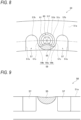
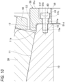
Fig. 6 is a sectional view of the conical roller bearing 1 according to the second embodiment of the present invention.Fig. 7 is a sectional view of a main part of the conical roller bearing 1 inFig. 6 .Fig. 8 is a view of theflange member 50 inFig. 7 as viewed in a direction of an arrow IIX.Fig. 9 is a view of theflange member 50 inFig. 7 as viewed in a direction of an arrow IX.Fig. 10 is a sectional view of a main part of the conical roller bearing 1 before thecaulking portion 55 is formed. - As shown in
Figs. 7 to 9 , thebase 51 includes arecess 51b recessed from theother end surface 51a in the axial direction toward one side in the axial direction. Therecess 51b functions as a seating portion on which thehead 61 of thebolt 60 is seated. As shown inFig. 8 , the edge (peripheral wall) 51f of therecess 51b in the present embodiment has a circular shape as viewed in the axial direction, and has a shape closed in both the radial direction (the upper-lower direction inFigs. 7 and8 ) and the circumferential direction (the left-right direction inFig. 8 ). - The through
hole 51e penetrating from thebottom surface 51c (the other end surface in the axial direction) of therecess 51b to oneend surface 51d of the base 51 in the axial direction is formed in thebase 51. The throughhole 51e is provided at a position facing the threadedhole 15a of theinner ring boss 15 in the axial direction. Accordingly, as in the illustrated embodiment, the throughholes 51e and therecesses 51b in which the throughholes 51e are respectively formed are provided in the same number as the threadedholes 15a. - The
bolt 60 passes through the throughhole 51e of thebase 51 and is screwed into the threadedhole 15a of theinner ring boss 15 to extend in the axial direction, thereby fastening theinner ring boss 15 and theflange member 50 in the axial direction. In this case, thehead 61 of thebolt 60 is seated on therecess 51b of thebase 51. - The
projection 53 of theflange member 50 fastened to theinner ring boss 15 is positioned on the radially outer side of theother end 11a in the axial direction of the innerring raceway surface 11 and faces theconical rollers 30 in the axial direction, so as to prevent theconical rollers 30 from falling off to the other end side in the axial direction. In this way, theflange member 50 constitutes a small flange of theinner ring 10. - Here, as shown in
Figs. 6 to 9 , theflange member 50 includes thecaulking portion 55 that presses thehead 61 of thebolt 60 from the other end side in the axial direction. InFigs. 8 and 9 , thecaulking portion 55 is indicated by a hatched region. Thecaulking portion 55 extends from at least a part of theedge 51f of therecess 51b so as to overlap thehead 61 of thebolt 60. Thecaulking portion 55 in the present embodiment extends from a radially inner side portion of theedge 51f of therecess 51b to the radially outer side and presses a radially inner side portion of thehead 61 of thebolt 60 from the other end side in the axial direction. Thecaulking portion 55 is formed by plastically deforming thethin wall 59 shown inFigs. 8 and10 with a tool such as a punch. - As shown in
Figs. 8 and 9 , thebase 51 of theflange member 50 is formed with a pair ofgrooves 57 recessed from theother end surface 51a in the axial direction toward one side in the axial direction on a side opposite to thehead 61 of thebolt 60 and therecess 51b with thecaulking portion 55 interposed therebetween (on a radially inner side and both sides in the circumferential direction of thecaulking portion 55 in the illustrated embodiment). That is, the pair ofgrooves 57 in the present embodiment are recessed at positions separated from therecess 51b on both sides of therecess 51b in the circumferential direction. Note that a part of thegrooves 57 is also provided on the radially inner side of therecess 51b. The depth (width in the axial direction) of the illustratedgrooves 57 is substantially the same as the depth (width in the axial direction) of therecess 51b, but is not particularly limited thereto. - As shown in
Figs. 8 and 9 , thegrooves 57 of the present embodiment are open toward the radially inner side. As shown inFig. 8 , as viewed from the axial direction, the edge (peripheral wall) of each of thegrooves 57 includes astraight wall 57a extending substantially straight in the radial direction at a position separated from therecess 51b and thecaulking portion 55 in the circumferential direction, asemicircular wall 57b connected to a radially outer side end of thestraight wall 57a and extending to the radially outer side in a manner of folding back in a substantially semicircular shape, and aquadrant wall 57c connected to a radially inner side end of thesemicircular wall 57b on the side close to therecess 51b and thecaulking portion 55 and extending to the radially inner side in a manner of folding back in a substantially quadrant shape. Thequadrant walls grooves recess 51b and thecaulking portion 55. - As shown in
Figs. 8 and10 , thethin wall 59 is provided between therecess 51b and the pair ofgrooves thin wall 59 in the illustrated embodiment is provided between therecess 51b and thequadrant walls grooves 57. Thecaulking portion 55 is obtained by plastically deforming aportion 59a of thethin wall 59 on the radially inner side toward the radially outer side using a tool such as a punch. Thecaulking portion 55 prevents thebolt 60 from falling off even when thebolt 60 is loosened. - Note that in the embodiment of
Fig. 8 , thecaulking portion 55 is obtained by plastically deforming theportion 59a of thethin wall 59 on the radially inner side toward the radially outer side, but is not limited thereto, and thecaulking portion 55 may be obtained by plastically deformingportions thin wall 59 on both sides in the circumferential direction toward an inner side in the circumferential direction, which is a side of thehead 61 of thebolt 60. - The
groove 57 may not necessarily be provided in a pair at positions separated from therecess 51b on both sides of therecess 51b in the circumferential direction, and may at least be provided at a position separated from therecess 51b on at least one of both sides of therecess 51b in the circumferential direction. -
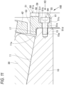
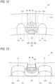
Fig. 11 is a sectional view of a main part of the conical roller bearing 1 according to a first modification of the second embodiment.Fig. 12 is a view of theflange member 50 inFig. 11 as viewed in a direction of an arrow XII.Fig. 13 is a view of theflange member 50 inFig. 11 as viewed in a direction of an arrow XIII. - As shown in
Figs. 11 to 13 , in the present modification, the throughgroove 58 that penetrates the base 51 in the radial direction is formed in a portion of thebase 51 of theflange member 50 that faces a tip (the other end in the axial direction, the right end inFig. 11 ) of thecaulking portion 55 in the radial direction. The throughgroove 58 is used to release the caulking of thecaulking portion 55 when thebolt 60 is removed during maintenance or the like. That is, when the caulking of thecaulking portion 55 is released, a tool such as a punch is inserted from the radially outer side of thebase 51 via the throughgroove 58, and thecaulking portion 55 is plastically deformed toward the radially inner side. Thebolt 60 released from pressing by thecaulking portion 55 becomes detachable. According to such a configuration, maintainability of the conical roller bearing 1 can be improved. -
Fig. 14 is a view of a main part of theflange member 50 according to a second modification of the second embodiment as viewed from the other side in the axial direction. Theflange member 50 of the present modification is different from theflange member 50 of the second embodiment (seeFig. 8 ) in that thecaulking portion 55 is formed on the whole circumference of theedge 51f of therecess 51b. - As shown in
Fig. 14 , theflange member 50 includes thecaulking portion 55 that presses thehead 61 of thebolt 60 from the other end side in the axial direction. InFig. 14 , thecaulking portion 55 is indicated by a hatched region. Thecaulking portion 55 extends from the whole circumference of theedge 51f of therecess 51b toward the center of thehead 61 of thebolt 60 and overlaps thehead 61. Thecaulking portion 55 presses the whole circumference of thehead 61 of thebolt 60 from the other end side in the axial direction. Thecaulking portion 55 is formed by plastically deforming thethin wall 59 between the whole circumference of theedge 51f of therecess 51b and thegroove 57 formed around theedge 51f using a tool such as a punch. - The
base 51 of theflange member 50 is formed with agroove 57 recessed from theother end surface 51a in the axial direction toward one side in the axial direction on a side opposite to thehead 61 of thebolt 60 and therecess 51b with thecaulking portion 55 interposed therebetween. Thegroove 57 opens to the radially inner side. As shown inFig. 14 , when viewed from the axial direction, anedge 57d (peripheral wall) of thegroove 57 has a substantially semicircular shape. - The
groove 57 is formed to have dimensions in the circumferential direction and the radial direction larger than those of thehead 61 of thebolt 60 and therecess 51b of thebase 51. Accordingly, as shown inFig. 14 , when viewed from the axial direction, thehead 61 of thebolt 60 and therecess 51b of the base 51 are disposed inside thegroove 57. Thethin wall 59 is formed between thegroove 57 and the whole circumference of theedge 51f of therecess 51b. - The
thin wall 59 is plastically deformed toward thehead 61 of thebolt 60 by a tool such as a punch, thereby obtaining thecaulking portion 55. Thecaulking portion 55 prevents thebolt 60 from falling off even when thebolt 60 is loosened. Especially, in the present modification, thecaulking portion 55 extends from the whole circumference of theedge 51f of therecess 51b and extends so as to overlap the whole circumference of thehead 61 of thebolt 60, and therefore the effect of preventing thebolt 60 from falling off is excellent. - Note that the present invention is not limited to the above-described embodiment, and various modifications can be made. For example, the present invention can be applied to a roller bearing such as a cylindrical roller bearing other than the conical roller bearing.
- For example, in the above-described embodiment, the
inner ring boss 15 protruding from the innerring raceway surface 11 toward the other end side in the axial direction is formed at the other end of theinner ring 10 in the axial direction, but theinner ring boss 15 may not be provided. When theinner ring boss 15 is not formed, theflange member 50 is disposed at the other end of theinner ring 10 in the axial direction (at a position adjacent to theother end 11a of the innerring raceway surface 11 in the axial direction) as in Patent Literature 1 (JP2014- 190352A inner ring boss 15 is not formed, theinner ring 10 does not have the steppedportion 17, and theflange member 50 does not have theprojection 53. The threadedhole 15a is formed from the other end surface of theinner ring 10 in the axial direction toward one end side in the axial direction. - In the above-described embodiment, the
flange member 50 is recessed from theother end surface 51a of the base 51 in the axial direction toward one side in the axial direction, and has therecess 51b on which thehead 61 of thebolt 60 is seated, but therecess 51b may not be formed in theflange member 50. In this case, the throughhole 51e is formed to penetrate from theother end surface 51a of the base 51 in the axial direction to oneend surface 51d in the axial direction, and thehead 61 of thebolt 60 is seated on theother end surface 51a of the base 51 in the axial direction. Also in this case, thecaulking portion 55 that presses thehead 61 of thebolt 60 from the other end side in the axial direction is formed in theflange member 50, and thegroove 57 extending from theother end surface 51a of the base 51 in the axial direction toward one side in the axial direction is provided in thebase 51 of theflange member 50 on a side opposite to thehead 61 of thebolt 60 with thecaulking portion 55 interposed therebetween. - As described above, the following matters are disclosed in the present specification.
- (1) A roller bearing, including:
- an inner ring including an outer peripheral surface having an inner ring raceway surface;
- an outer ring including an inner peripheral surface having an outer ring raceway surface; and
- a plurality of rollers disposed such that the rollers are capable of rolling between the inner ring raceway surface and the outer ring raceway surface, in which
- a flange integrated with the inner ring is formed at one end of the inner ring in an axial direction,
- a flange member separate from the inner ring is fastened to a fastening member extending in the axial direction at the other end of the inner ring in the axial direction, and
- the flange member includes
- a base abutting against the inner ring in the axial direction and on which a head of the fastening member is seated, and
- a caulking portion pressing the head of the fastening member from the other end side in the axial direction.
- (2) The roller bearing according to (1), in which
- the flange member includes a recess recessed from the other end surface of the base in the axial direction toward one side in the axial direction and on which the head of the fastening member is seated, and
- the base of the flange member includes a groove recessed from the other end surface of the base in the axial direction toward one side in the axial direction at a position separated from the recess and on a radially outer side of the recess.
- (3) The roller bearing according to (1), in which
- the flange member includes a recess recessed from the other end surface of the base in the axial direction toward one side in the axial direction and on which the head of the fastening member is seated, and
- the base of the flange member includes a groove recessed from the other end surface of the base in the axial direction toward one side in the axial direction at a position separated from the recess and on at least one of both sides of the recess in a circumferential direction.
- (4) The roller bearing according to any one of (1) to (3), in which
the base of the flange member is provided with a groove on a side opposite to the head of the fastening member with the caulking portion interposed therebetween, and recessed from the other end surface of the base in the axial direction toward one side in the axial direction. - (5) The roller bearing according to any one of (1) to (4), in which
- the flange member includes a recess recessed from the other end surface of the base in the axial direction toward one side in the axial direction and on which the head of the fastening member is seated, and
- the caulking portion extends from at least a part of an edge of the recess and extends so as to overlap the head of the fastening member.
- (6) The roller bearing according to (5), in which
the caulking portion extends from a whole circumference of the edge of the recess and extends so as to overlap a whole circumference of the head of the fastening member. - (7) The roller bearing according to any one of (1) to (6), in which
- the other end of the inner ring in the axial direction is formed with an inner ring boss protruding from the inner ring raceway surface toward the other end side in the axial direction,
- the flange member is fastened to the inner ring boss by the fastening member, and
- the fastening member does not overlap the inner ring raceway surface in the axial direction.
- Although various embodiments have been described above, it goes without saying that the present invention is not limited to such embodiments. It is apparent for those skilled in the art to which the present invention belongs that various modified examples or corrected examples are conceivable within the scope recited in the claims, and it is understood that the above falls within the technical scope of the present invention. In addition, within the scope not departing from the gist of the invention, each of the configuration elements in the above embodiments may be combined in any manner.
- The present application is based on
Japanese Patent Application No. 2022-069472 filed on April 20, 2022 Japanese Patent Application No. 2022-146395 filed on September 14, 2022 Japanese Patent Application No. 2023-020158 filed on February 13, 2023 -
- 1 conical roller bearing (roller bearing)
- 10 inner ring
- 11 inner ring raceway surface
- 11a the other end in the axial direction
- 13 flange
- 15 inner ring boss
- 15a threaded hole
- 17 stepped portion
- 20 outer ring
- 21 outer ring raceway surface
- 30 conical roller (roller)
- 40 cage
- 41, 42 annular portion
- 43 pin
- 50 flange member
- 51 base
- 51a the other end surface in the axial direction
- 51b recess
- 51c bottom surface
- 51d one end surface in the axial direction
- 51e through hole
- 51f edge
- 53 projection
- 55 caulking portion
- 57 groove
- 57a straight wall
- 57b semicircular wall
- 57c quadrant wall
- 57d edge
- 58 through groove
- 59 thin wall
- 59a portion on the radially inner side
- 59b both sides in the circumferential direction
- 60 bolt (fastening member)
- 61 head
- A, B virtual plane
Claims (7)
- A roller bearing, comprising:an inner ring including an outer peripheral surface having an inner ring raceway surface;an outer ring including an inner peripheral surface having an outer ring raceway surface; anda plurality of rollers disposed such that the rollers are capable of rolling between the inner ring raceway surface and the outer ring raceway surface, wherein:a flange integrated with the inner ring is formed at one end of the inner ring in an axial direction;a flange member separate from the inner ring is fastened to a fastening member extending in the axial direction at the other end of the inner ring in the axial direction; andthe flange member includes:a base abutting against the inner ring in the axial direction and on which a head of the fastening member is seated; anda caulking portion pressing the head of the fastening member from the other end side in the axial direction.
- The roller bearing according to claim 1, wherein:the flange member includes a recess recessed from the other end surface of the base in the axial direction toward one side in the axial direction and on which the head of the fastening member is seated; andthe base of the flange member includes a groove recessed from the other end surface of the base in the axial direction toward one side in the axial direction at a position separated from the recess and on a radially outer side of the recess.
- The roller bearing according to claim 1, wherein:the flange member includes a recess recessed from the other end surface of the base in the axial direction toward one side in the axial direction and on which the head of the fastening member is seated; andthe base of the flange member includes a groove recessed from the other end surface of the base in the axial direction toward one side in the axial direction at a position separated from the recess and on at least one of both sides of the recess in a circumferential direction.
- The roller bearing according to claim 1, wherein
the base of the flange member is provided with a groove on a side opposite to the head of the fastening member with the caulking portion interposed therebetween, and recessed from the other end surface of the base in the axial direction toward one side in the axial direction. - The roller bearing according to claim 1, wherein:the flange member includes a recess recessed from the other end surface of the base in the axial direction toward one side in the axial direction and on which the head of the fastening member is seated; andthe caulking portion extends from at least a part of an edge of the recess and extends so as to overlap the head of the fastening member.
- The roller bearing according to claim 5, wherein
the caulking portion extends from a whole circumference of the edge of the recess and extends so as to overlap a whole circumference of the head of the fastening member. - The roller bearing according to any one of claims 1 to 6, wherein:the other end of the inner ring in the axial direction is formed with an inner ring boss protruding from the inner ring raceway surface toward the other end side in the axial direction;the flange member is fastened to the inner ring boss by the fastening member; andthe fastening member does not overlap the inner ring raceway surface in the axial direction.
Applications Claiming Priority (4)
| Application Number | Priority Date | Filing Date | Title |
|---|---|---|---|
| JP2022069472 | 2022-04-20 | ||
| JP2022146395 | 2022-09-14 | ||
| JP2023020158A JP2023159859A (en) | 2022-04-20 | 2023-02-13 | roller bearing |
| PCT/JP2023/015240 WO2023204161A1 (en) | 2022-04-20 | 2023-04-14 | Roller bearing |
Publications (2)
| Publication Number | Publication Date |
|---|---|
| EP4513048A1 true EP4513048A1 (en) | 2025-02-26 |
| EP4513048A4 EP4513048A4 (en) | 2025-09-17 |
Family
ID=88419819
Family Applications (1)
| Application Number | Title | Priority Date | Filing Date |
|---|---|---|---|
| EP23791809.9A Pending EP4513048A4 (en) | 2022-04-20 | 2023-04-14 | ROLLER BEARINGS |
Country Status (5)
| Country | Link |
|---|---|
| US (1) | US20250271029A1 (en) |
| EP (1) | EP4513048A4 (en) |
| CN (1) | CN119053796A (en) |
| AU (1) | AU2023256365A1 (en) |
| WO (1) | WO2023204161A1 (en) |
Family Cites Families (10)
| Publication number | Priority date | Publication date | Assignee | Title |
|---|---|---|---|---|
| JP2006207731A (en) * | 2005-01-28 | 2006-08-10 | Nsk Ltd | Roller bearing |
| DE102005047270B4 (en) * | 2005-10-01 | 2016-03-10 | Schaeffler Technologies AG & Co. KG | roller bearing |
| DE102008048095A1 (en) * | 2008-09-19 | 2010-03-25 | Huf Hülsbeck & Fürst Gmbh & Co. Kg | Safety arrangement for the captive acceptance of a connecting element on a component |
| JP2013015200A (en) * | 2011-07-05 | 2013-01-24 | Jtekt Corp | Conical roller bearing |
| JP2013015201A (en) * | 2011-07-05 | 2013-01-24 | Jtekt Corp | Tapered roller bearing |
| JP2014190352A (en) | 2013-03-26 | 2014-10-06 | Nakanishi Metal Works Co Ltd | Taper roller bearing |
| JP7074776B2 (en) | 2018-01-24 | 2022-05-24 | 富士フイルム株式会社 | Photosensitive transfer material and its manufacturing method, resin pattern manufacturing method, and circuit wiring manufacturing method. |
| JP2022146395A (en) | 2021-03-22 | 2022-10-05 | 株式会社ジャパンディスプレイ | Display device |
| JP7742733B2 (en) | 2021-07-30 | 2025-09-22 | 朝日インテック株式会社 | Supported Devices |
| JP2023072404A (en) * | 2021-11-12 | 2023-05-24 | 日本精工株式会社 | roller bearing |
-
2023
- 2023-04-14 EP EP23791809.9A patent/EP4513048A4/en active Pending
- 2023-04-14 CN CN202380035258.2A patent/CN119053796A/en active Pending
- 2023-04-14 US US18/858,156 patent/US20250271029A1/en active Pending
- 2023-04-14 AU AU2023256365A patent/AU2023256365A1/en active Pending
- 2023-04-14 WO PCT/JP2023/015240 patent/WO2023204161A1/en not_active Ceased
Also Published As
| Publication number | Publication date |
|---|---|
| WO2023204161A1 (en) | 2023-10-26 |
| AU2023256365A1 (en) | 2024-11-07 |
| EP4513048A4 (en) | 2025-09-17 |
| CN119053796A (en) | 2024-11-29 |
| US20250271029A1 (en) | 2025-08-28 |
Similar Documents
| Publication | Publication Date | Title |
|---|---|---|
| US20020020968A1 (en) | Brush seal | |
| US20170175813A1 (en) | Cylindrical roller bearing | |
| EP2853762B1 (en) | Rolling bearing unit with mounting plate, and method for manufacturing same | |
| US20160334007A1 (en) | Planetary gear pin with flange that can be bolted to the planetary carrier | |
| EP3156675B1 (en) | Bearing device and method for manufacturing bearing device | |
| US20250271029A1 (en) | Roller bearing | |
| US10352431B2 (en) | Transmission case | |
| US9903416B2 (en) | Bearing device and method for manufacturing bearing device | |
| US8337092B2 (en) | Retainer-equipped roller | |
| KR20200029496A (en) | Rolling bearing and retainer | |
| US11067115B2 (en) | Spherical ball joint | |
| EP2042756B1 (en) | Cage, production method for the cage, thrust roller bearing equipped with the cage | |
| JP7268496B2 (en) | roller bearing | |
| JP2011219208A (en) | Suspender for rolling bearing and assembling method of rolling bearing | |
| JP2017020606A (en) | Bearing device | |
| JP2009210018A (en) | Roller bearing | |
| CN213655672U (en) | Sealing mechanism and gear box | |
| JP2023072404A (en) | roller bearing | |
| JP2017015233A (en) | Rolling bearing device | |
| JP4779953B2 (en) | Bearing unit manufacturing method and bearing unit | |
| JP7845119B2 (en) | Roller bearings | |
| JP2024039336A (en) | Roller bearings and double row roller bearings | |
| EP4414574A1 (en) | Roller bearing for supporting wheel | |
| JP2007218394A (en) | Two-split bearing | |
| JP2023159645A (en) | roller bearing |
Legal Events
| Date | Code | Title | Description |
|---|---|---|---|
| STAA | Information on the status of an ep patent application or granted ep patent |
Free format text: STATUS: THE INTERNATIONAL PUBLICATION HAS BEEN MADE |
|
| PUAI | Public reference made under article 153(3) epc to a published international application that has entered the european phase |
Free format text: ORIGINAL CODE: 0009012 |
|
| STAA | Information on the status of an ep patent application or granted ep patent |
Free format text: STATUS: REQUEST FOR EXAMINATION WAS MADE |
|
| 17P | Request for examination filed |
Effective date: 20241017 |
|
| AK | Designated contracting states |
Kind code of ref document: A1 Designated state(s): AL AT BE BG CH CY CZ DE DK EE ES FI FR GB GR HR HU IE IS IT LI LT LU LV MC ME MK MT NL NO PL PT RO RS SE SI SK SM TR |
|
| DAV | Request for validation of the european patent (deleted) | ||
| DAX | Request for extension of the european patent (deleted) | ||
| A4 | Supplementary search report drawn up and despatched |
Effective date: 20250818 |
|
| RIC1 | Information provided on ipc code assigned before grant |
Ipc: F16C 33/60 20060101AFI20250811BHEP Ipc: F16C 19/36 20060101ALI20250811BHEP |