EP4512992A2 - Vorrichtung mit einem löslichen material zur verwendung in einem bohrloch - Google Patents
Vorrichtung mit einem löslichen material zur verwendung in einem bohrloch Download PDFInfo
- Publication number
- EP4512992A2 EP4512992A2 EP25151754.6A EP25151754A EP4512992A2 EP 4512992 A2 EP4512992 A2 EP 4512992A2 EP 25151754 A EP25151754 A EP 25151754A EP 4512992 A2 EP4512992 A2 EP 4512992A2
- Authority
- EP
- European Patent Office
- Prior art keywords
- tubing
- dissolvable
- dissolvable material
- noble
- electrically insulating
- Prior art date
- Legal status (The legal status is an assumption and is not a legal conclusion. Google has not performed a legal analysis and makes no representation as to the accuracy of the status listed.)
- Pending
Links
Images
Classifications
-
- E—FIXED CONSTRUCTIONS
- E21—EARTH OR ROCK DRILLING; MINING
- E21B—EARTH OR ROCK DRILLING; OBTAINING OIL, GAS, WATER, SOLUBLE OR MELTABLE MATERIALS OR A SLURRY OF MINERALS FROM WELLS
- E21B29/00—Cutting or destroying pipes, packers, plugs or wire lines, located in boreholes or wells, e.g. cutting of damaged pipes, of windows; Deforming of pipes in boreholes or wells; Reconditioning of well casings while in the ground
- E21B29/02—Cutting or destroying pipes, packers, plugs or wire lines, located in boreholes or wells, e.g. cutting of damaged pipes, of windows; Deforming of pipes in boreholes or wells; Reconditioning of well casings while in the ground by explosives or by thermal or chemical means
-
- E—FIXED CONSTRUCTIONS
- E21—EARTH OR ROCK DRILLING; MINING
- E21B—EARTH OR ROCK DRILLING; OBTAINING OIL, GAS, WATER, SOLUBLE OR MELTABLE MATERIALS OR A SLURRY OF MINERALS FROM WELLS
- E21B33/00—Sealing or packing boreholes or wells
- E21B33/10—Sealing or packing boreholes or wells in the borehole
- E21B33/12—Packers; Plugs
- E21B33/1208—Packers; Plugs characterised by the construction of the sealing or packing means
-
- E—FIXED CONSTRUCTIONS
- E21—EARTH OR ROCK DRILLING; MINING
- E21B—EARTH OR ROCK DRILLING; OBTAINING OIL, GAS, WATER, SOLUBLE OR MELTABLE MATERIALS OR A SLURRY OF MINERALS FROM WELLS
- E21B34/00—Valve arrangements for boreholes or wells
- E21B34/06—Valve arrangements for boreholes or wells in wells
- E21B34/063—Valve or closure with destructible element, e.g. frangible disc
-
- E—FIXED CONSTRUCTIONS
- E21—EARTH OR ROCK DRILLING; MINING
- E21B—EARTH OR ROCK DRILLING; OBTAINING OIL, GAS, WATER, SOLUBLE OR MELTABLE MATERIALS OR A SLURRY OF MINERALS FROM WELLS
- E21B34/00—Valve arrangements for boreholes or wells
- E21B34/06—Valve arrangements for boreholes or wells in wells
- E21B34/08—Valve arrangements for boreholes or wells in wells responsive to flow or pressure of the fluid obtained
- E21B34/085—Valve arrangements for boreholes or wells in wells responsive to flow or pressure of the fluid obtained with time-delay systems, e.g. hydraulic impedance mechanisms
-
- E—FIXED CONSTRUCTIONS
- E21—EARTH OR ROCK DRILLING; MINING
- E21B—EARTH OR ROCK DRILLING; OBTAINING OIL, GAS, WATER, SOLUBLE OR MELTABLE MATERIALS OR A SLURRY OF MINERALS FROM WELLS
- E21B43/00—Methods or apparatus for obtaining oil, gas, water, soluble or meltable materials or a slurry of minerals from wells
- E21B43/12—Methods or apparatus for controlling the flow of the obtained fluid to or in wells
-
- E—FIXED CONSTRUCTIONS
- E21—EARTH OR ROCK DRILLING; MINING
- E21B—EARTH OR ROCK DRILLING; OBTAINING OIL, GAS, WATER, SOLUBLE OR MELTABLE MATERIALS OR A SLURRY OF MINERALS FROM WELLS
- E21B2200/00—Special features related to earth drilling for obtaining oil, gas or water
- E21B2200/08—Down-hole devices using materials which decompose under well-bore conditions
Definitions
- the invention relates to a device for use in a wellbore, the device comprising a dissolvable material for being dissolved over a limited time period, to a tubing comprising the device, and to use of the device.
- Dissolving material has been used in oil and gas wells for several years to create temporary barriers or activate downhole tools. The process takes place when a dissolvable material, typically a special alloy of magnesium, is in contact with chloride-containing water. However, the dissolvable material at times dissolves too quickly, at least partly because the plug is usually very small, whereby the time period of the effect is too short.
- the invention has for its object to remedy or to reduce at least one of the drawbacks of the prior art, or at least provide a useful alternative to prior art.
- the object is achieved through features which are specified in the description below and in the claims that follow.
- the invention is defined by the independent patent claims, and the dependent claims define advantageous embodiments of the invention.
- the invention relates more particularly to a device for use in a wellbore, the device comprising a dissolvable material for being dissolved over a limited time period, wherein the device further comprises an electrically insulating material covering a portion of the dissolvable material for keeping the dissolvable material out of contact with any more noble material when the device is in use.
- the dissolvable material and the more noble material may typically both be metals, and the dissolution of the dissolvable material may for example occur by corrosion such as oxidation.
- the device is typically in contact with a fluid, for example saltwater or a wellbore fluid, which may act as an electrolyte.
- the invention is based on the observation that the dissolvable materials used in prior art are generally susceptible to galvanic corrosion and are positioned at locations in the wellbore where they are in electrical connection with a more noble material. This will allow electrons to be transferred from the dissolvable material to the more noble material via the electrical connection, which will cause galvanic corrosion of the material which is less noble, i.e. the one which has the lowest electrode potential. This may significantly increase the rate of dissolution of the dissolvable material when it is susceptible to galvanic corrosion, as it typically has a low electrode potential.
- the device includes an electrically insulating material, which prevents or at least decreases electrical connection between the dissolvable material and any more noble material. This has been observed to considerably decrease the rate of dissolution of the dissolvable materials which are typically used, since the rapid dissolution of the dissolvable material by galvanic corrosion is avoided.
- the dissolvable material may thereby function for a much longer time, sometimes more than five times than if the electrically insulating material were not included. This effect is larger the smaller the dissolvable material part is.
- An important effect of the device is therefore to provide device comprising a dissolvable material, wherein the dissolution process is better controlled regardless of the dissolvable material used. For the dissolvable material to dissolve, a portion of the dissolvable material must be in contact with an electrolyte when the device is in use. Therefore, the insulating material cannot cover the entire surface of the dissolvable material.
- the electrically insulating material may be a structural part of the device, for example a ceramic structure configured to have a function in the wellbore after dissolution of the dissolvable material. It may also be applied as a thin coating onto the dissolvable material, whereby its only function is to prevent electrical connection between the first and more noble material.
- the electrically insulating material may be any non-conducting material, for example a ceramic or a plastic material, depending on what is most suitable for the specific application of the device.
- the more noble material may be a part of the device itself, for example if the device is configured to block fluid flow for a limited time and the restrict fluid flow after the dissolvable material is dissolved.
- the device may for example comprise a nozzle made of the more noble material which provides strength and resist long-term wear, a plug made of the dissolvable material for blocking fluid flow for a limited time, and an electrically insulating material between the two to prevent electrical connection, thereby increasing the time period in which the device functions as a plug.
- the more noble material may be a part of the surroundings, for example a metal tubing in the wellbore.
- the device may comprise a nozzle constructed in a strong, electrically insulating material, for example a ceramic material.
- a strong, electrically insulating material for example a ceramic material.
- the more noble material may be a part of a complementary tool connected to the device. The more noble material may typically be steel or tungsten carbide, as these materials are often used in wellbores.
- the dissolvable material may for example comprise magnesium or a magnesium alloy, which has been shown to be able to dissolve within a time period which is suitable for some applications in a wellbore.
- magnesium is susceptible to galvanic corrosion, and it is furthermore positioned at the bottom section of the galvanic series, i.e. it is one of the least noble metals. Dissolution of a dissolvable material comprising magnesium therefore occurs very rapidly if the dissolvable material is in contact with another metal.
- use of magnesium in the dissolvable material assures that it is the dissolvable material which undergoes galvanic corrosion in case of electrical connection, and not any other part of the device or the surroundings.
- the electrically insulating material may be arranged so that, when the device is in contact with a fluid, any distance between the dissolvable material and the more noble material measured through the fluid is longer than a predetermined value.
- the predetermined value may for example be selected to be large enough to avoid or significantly decrease the risk of an electrical connection being formed through the fluid by an electrically conducting component.
- a small portion of the dissolvable material may remain as debris close to the device.
- the debris may for example comprise zinc, aluminum, or a biproduct from the dissolution. If the distance between the dissolvable material and the more noble material of the device is short, particles from debris may form a bridge between the dissolvable material and the more noble material which may conduct electricity. This may cause galvanic corrosion and speed up the dissolution rate if the dissolvable material is susceptible to galvanic corrosion. Speeding up the dissolution rate is generally undesirable.
- the electrically insulating material may be arranged so that a contact area between the dissolvable material and the fluid is selected to cause the dissolvable material to dissolve over a predetermined time period. Since the dissolution of the dissolvable material occurs when it is in contact with the fluid, the rate of dissolution will depend on the area of the dissolvable material which is in contact with the fluid. Therefore, for a specific fluid and dissolvable material, it will be possible to find a correlation between the contact area and time it takes for the dissolvable material to dissolve. This correlation may be exploited to select the contact area based on the time period over which it is desired that the dissolvable material dissolves.
- the device may typically be configured to block the flow of the fluid for a limited time period.
- the device may be configured to limit fluid flow for a limited time period.
- the invention in a second aspect, relates to a tubing comprising the device according to the first aspect of the invention.
- the device may for example be installed and configured to block the flow of the fluid for a limited time in the radial direction of the tubing.
- a tubing comprising the device in such a configuration may be particularly useful in the completion step when the tubing is run in the wellbore.
- the tubing will in this situation allow circulation of fluid through the bottom of the liner to displace the entire wellbore with the desired fluid, function as a mean for well control in case of unexpected pressure build-up, or simply function as a means for fluid circulation and aid installation of tubulars.
- the tubing comprising the devices can be run in the wellbore with a closed end, it can be used to pressurize the tubing, set production packers, and perform barrier test of the tubing.
- the invention relates to use of the device according to the first aspect to block fluid flow in a wellbore for a limited time period.
- the reference numeral 1 indicates a device according to the invention. Identical reference numerals indicate identical or similar features in the drawings.
- the drawings are presented in a simplified and schematic manner, and the features therein are not necessarily drawn to scale.
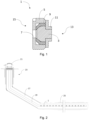
- Figure 1 shows a sectioned view of an embodiment of the device 1 according to the invention.
- the device 1 comprises a dissolvable material 3 in the form of a plug which blocks the flow of fluid until the dissolvable material 3 has dissolved.
- the device 1 also comprises a more noble material 5 in the form of a nozzle configured to restrict the flow of the fluid through an opening 7 after the dissolvable material 3 has dissolved.
- An electrically insulating material 9 covers a portion of the dissolvable material 3 to keep the dissolvable material 3 out of contact with the more noble material 5.
- the device 1 comprises a further electrically insulating material 11 to increase the distance between the dissolvable material 3 and the more noble material 5 measured through the fluid when the device 1 is in use in a wellbore.
- the device 1 has a first side 13 and a second side 15.
- the first side 13 When the device 1 is in use in the wellbore, the first side 13 will be in contact with the fluid which acts as an electrolyte. The dissolution of the dissolvable material 3 will therefore occur on the first side 13, and the distance between the dissolvable material 3 and the more noble material 5 is longer on the first side 13 than on the second side 15.
- the device 1 is configured to be positioned within an opening complementing the more noble material 5 so that there is no direct fluid communication between the first side 13 and the second side 15 when the device 1 is in use before the dissolvable material 3 has dissolved.
- Figure 2 shows a wellbore 17 comprising a production tubing 19 installed within.
- the wellhead 21 and casing 23 is also indicated.
- the production tubing 19 comprises a plurality of the devices 1 in the radial surface of the production tubing 19.
- fluid can initially be pumped through the tubing 19 along the longitudinal axis, but flow through the side of the tubing 19 via the devices 1 is prevented. This may for example be beneficial during the completion step as described above.
- the dissolvable material 3 has dissolved, and hydrocarbon flow from the reservoir 25 can be produced through the openings 7 of the devices 1.
Landscapes
- Geology (AREA)
- Life Sciences & Earth Sciences (AREA)
- Engineering & Computer Science (AREA)
- Mining & Mineral Resources (AREA)
- Geochemistry & Mineralogy (AREA)
- Fluid Mechanics (AREA)
- Environmental & Geological Engineering (AREA)
- General Life Sciences & Earth Sciences (AREA)
- Physics & Mathematics (AREA)
- General Chemical & Material Sciences (AREA)
- Chemical Kinetics & Catalysis (AREA)
- Chemical & Material Sciences (AREA)
- Physical Or Chemical Processes And Apparatus (AREA)
- Cosmetics (AREA)
- Infusion, Injection, And Reservoir Apparatuses (AREA)
- Compositions Of Oxide Ceramics (AREA)
- Motor Or Generator Current Collectors (AREA)
- Drilling Tools (AREA)
- Hydrogen, Water And Hydrids (AREA)
Applications Claiming Priority (3)
| Application Number | Priority Date | Filing Date | Title |
|---|---|---|---|
| NO20191355A NO346335B1 (en) | 2019-11-15 | 2019-11-15 | A device comprising a dissolvable material for use in a wellbore |
| EP20888198.7A EP4058655B1 (de) | 2019-11-15 | 2020-11-04 | Vorrichtung mit einem auflösbaren material zur verwendung in einem bohrloch |
| PCT/NO2020/050269 WO2021096364A1 (en) | 2019-11-15 | 2020-11-04 | A device comprising a dissolvable material for use in a wellbore |
Related Parent Applications (2)
| Application Number | Title | Priority Date | Filing Date |
|---|---|---|---|
| EP20888198.7A Division EP4058655B1 (de) | 2019-11-15 | 2020-11-04 | Vorrichtung mit einem auflösbaren material zur verwendung in einem bohrloch |
| EP20888198.7A Division-Into EP4058655B1 (de) | 2019-11-15 | 2020-11-04 | Vorrichtung mit einem auflösbaren material zur verwendung in einem bohrloch |
Publications (2)
| Publication Number | Publication Date |
|---|---|
| EP4512992A2 true EP4512992A2 (de) | 2025-02-26 |
| EP4512992A3 EP4512992A3 (de) | 2025-07-09 |
Family
ID=75912283
Family Applications (2)
| Application Number | Title | Priority Date | Filing Date |
|---|---|---|---|
| EP25151754.6A Pending EP4512992A3 (de) | 2019-11-15 | 2020-11-04 | Vorrichtung mit einem löslichen material zur verwendung in einem bohrloch |
| EP20888198.7A Active EP4058655B1 (de) | 2019-11-15 | 2020-11-04 | Vorrichtung mit einem auflösbaren material zur verwendung in einem bohrloch |
Family Applications After (1)
| Application Number | Title | Priority Date | Filing Date |
|---|---|---|---|
| EP20888198.7A Active EP4058655B1 (de) | 2019-11-15 | 2020-11-04 | Vorrichtung mit einem auflösbaren material zur verwendung in einem bohrloch |
Country Status (6)
| Country | Link |
|---|---|
| US (1) | US12084941B2 (de) |
| EP (2) | EP4512992A3 (de) |
| DE (1) | DE20888198T9 (de) |
| NO (1) | NO346335B1 (de) |
| SA (1) | SA522432611B1 (de) |
| WO (1) | WO2021096364A1 (de) |
Families Citing this family (1)
| Publication number | Priority date | Publication date | Assignee | Title |
|---|---|---|---|---|
| CN114480923B (zh) * | 2022-01-26 | 2022-11-08 | 西南石油大学 | 一种溶解速度可控的可溶金属密封圈及其制备工艺 |
Family Cites Families (10)
| Publication number | Priority date | Publication date | Assignee | Title |
|---|---|---|---|---|
| US7699101B2 (en) * | 2006-12-07 | 2010-04-20 | Halliburton Energy Services, Inc. | Well system having galvanic time release plug |
| US9068428B2 (en) * | 2012-02-13 | 2015-06-30 | Baker Hughes Incorporated | Selectively corrodible downhole article and method of use |
| US9759035B2 (en) * | 2012-06-08 | 2017-09-12 | Halliburton Energy Services, Inc. | Methods of removing a wellbore isolation device using galvanic corrosion of a metal alloy in solid solution |
| US9458692B2 (en) * | 2012-06-08 | 2016-10-04 | Halliburton Energy Services, Inc. | Isolation devices having a nanolaminate of anode and cathode |
| US10273400B2 (en) | 2012-11-29 | 2019-04-30 | M-I L.L.C. | Colloidal silica and polymer system for insulating packer fluids |
| GB201418488D0 (en) * | 2014-10-17 | 2014-12-03 | Maersk Olie & Gas | Wellbore system and associated method |
| MX2018004423A (es) * | 2015-11-18 | 2018-05-11 | Halliburton Energy Services Inc | Material degradable afilado y resistente a la erosion para botones de deslizamiento y deflectores de camisa de deslizamiento. |
| US20180171743A1 (en) * | 2016-12-19 | 2018-06-21 | Schlumberger Technology Corporation | Cathodically-protected plug assembly |
| US20180328139A1 (en) | 2017-05-12 | 2018-11-15 | Weatherford Technology Holdings, Llc | Temporary Barrier for Inflow Control Device |
| WO2020214447A1 (en) * | 2019-04-16 | 2020-10-22 | NexGen Oil Tools Inc. | Dissolvable plugs used in downhill completion systems |
-
2019
- 2019-11-15 NO NO20191355A patent/NO346335B1/en unknown
-
2020
- 2020-11-04 EP EP25151754.6A patent/EP4512992A3/de active Pending
- 2020-11-04 DE DE20888198.7T patent/DE20888198T9/de active Active
- 2020-11-04 WO PCT/NO2020/050269 patent/WO2021096364A1/en not_active Ceased
- 2020-11-04 EP EP20888198.7A patent/EP4058655B1/de active Active
- 2020-11-04 US US17/775,483 patent/US12084941B2/en active Active
-
2022
- 2022-05-15 SA SA522432611A patent/SA522432611B1/ar unknown
Also Published As
| Publication number | Publication date |
|---|---|
| WO2021096364A1 (en) | 2021-05-20 |
| EP4058655A4 (de) | 2023-11-29 |
| EP4058655A1 (de) | 2022-09-21 |
| DE20888198T9 (de) | 2023-01-05 |
| US20220372834A1 (en) | 2022-11-24 |
| NO346335B1 (en) | 2022-06-13 |
| DE20888198T1 (de) | 2022-11-10 |
| EP4512992A3 (de) | 2025-07-09 |
| BR112022007249A2 (pt) | 2022-07-05 |
| NO20191355A1 (en) | 2021-05-17 |
| US12084941B2 (en) | 2024-09-10 |
| SA522432611B1 (ar) | 2025-05-06 |
| EP4058655B1 (de) | 2025-02-26 |
Similar Documents
| Publication | Publication Date | Title |
|---|---|---|
| AU2015408055B2 (en) | Top set degradable wellbore isolation device | |
| AU2020223711B2 (en) | Well system with degradable plug | |
| US10106872B2 (en) | Degradable downhole tools comprising magnesium alloys | |
| US7699101B2 (en) | Well system having galvanic time release plug | |
| CA2955925C (en) | Wellbore isolation devices with degradable slip assemblies with slip inserts | |
| NO348935B1 (en) | Coatings for a degradable wellbore isolation device, including a method of removing a wellbore isolation device and a system for use in a wellbore | |
| EP3097254B1 (de) | In einem bohrloch zementiertes werkzeug mit einem durch galvanische korrosion aufgelöstem anschlussstopfen | |
| CA2998846A1 (en) | Sharp and erosion resistance degradable material for slip buttons and sliding sleeve baffles | |
| US20200032625A1 (en) | Degradable Metal Barrier For Downhole Screens | |
| US12084941B2 (en) | Device comprising a dissolvable material for use in a wellbore | |
| BR112022007249B1 (pt) | Dispositivo para bloquear temporariamente o fluxo de fluido e tubulação | |
| WO2016186508A1 (en) | A method of perforating a tubular, a tubular and a tool therefor |
Legal Events
| Date | Code | Title | Description |
|---|---|---|---|
| PUAI | Public reference made under article 153(3) epc to a published international application that has entered the european phase |
Free format text: ORIGINAL CODE: 0009012 |
|
| STAA | Information on the status of an ep patent application or granted ep patent |
Free format text: STATUS: REQUEST FOR EXAMINATION WAS MADE |
|
| 17P | Request for examination filed |
Effective date: 20250114 |
|
| AC | Divisional application: reference to earlier application |
Ref document number: 4058655 Country of ref document: EP Kind code of ref document: P |
|
| AK | Designated contracting states |
Kind code of ref document: A2 Designated state(s): AL AT BE BG CH CY CZ DE DK EE ES FI FR GB GR HR HU IE IS IT LI LT LU LV MC MK MT NL NO PL PT RO RS SE SI SK SM TR |
|
| REG | Reference to a national code |
Ref country code: DE Ref legal event code: R079 Free format text: PREVIOUS MAIN CLASS: E21B0043120000 Ipc: E21B0033120000 |
|
| PUAL | Search report despatched |
Free format text: ORIGINAL CODE: 0009013 |
|
| AK | Designated contracting states |
Kind code of ref document: A3 Designated state(s): AL AT BE BG CH CY CZ DE DK EE ES FI FR GB GR HR HU IE IS IT LI LT LU LV MC MK MT NL NO PL PT RO RS SE SI SK SM TR |
|
| RIC1 | Information provided on ipc code assigned before grant |
Ipc: E21B 43/12 20060101ALI20250605BHEP Ipc: E21B 34/06 20060101ALI20250605BHEP Ipc: E21B 36/00 20060101ALI20250605BHEP Ipc: E21B 23/01 20060101ALI20250605BHEP Ipc: E21B 33/12 20060101AFI20250605BHEP |
|
| STAA | Information on the status of an ep patent application or granted ep patent |
Free format text: STATUS: EXAMINATION IS IN PROGRESS |
|
| 17Q | First examination report despatched |
Effective date: 20260330 |