EP4512963A1 - Working machine - Google Patents
Working machine Download PDFInfo
- Publication number
- EP4512963A1 EP4512963A1 EP24181914.3A EP24181914A EP4512963A1 EP 4512963 A1 EP4512963 A1 EP 4512963A1 EP 24181914 A EP24181914 A EP 24181914A EP 4512963 A1 EP4512963 A1 EP 4512963A1
- Authority
- EP
- European Patent Office
- Prior art keywords
- heat exchanger
- cooling medium
- heat
- hydraulic fluid
- cooling
- Prior art date
- Legal status (The legal status is an assumption and is not a legal conclusion. Google has not performed a legal analysis and makes no representation as to the accuracy of the status listed.)
- Granted
Links
Images





Classifications
-
- E—FIXED CONSTRUCTIONS
- E02—HYDRAULIC ENGINEERING; FOUNDATIONS; SOIL SHIFTING
- E02F—DREDGING; SOIL-SHIFTING
- E02F9/00—Component parts of dredgers or soil-shifting machines, not restricted to one of the kinds covered by groups E02F3/00 - E02F7/00
- E02F9/20—Drives; Control devices
- E02F9/2058—Electric or electro-mechanical or mechanical control devices of vehicle sub-units
- E02F9/2062—Control of propulsion units
- E02F9/2075—Control of propulsion units of the hybrid type
-
- E—FIXED CONSTRUCTIONS
- E02—HYDRAULIC ENGINEERING; FOUNDATIONS; SOIL SHIFTING
- E02F—DREDGING; SOIL-SHIFTING
- E02F9/00—Component parts of dredgers or soil-shifting machines, not restricted to one of the kinds covered by groups E02F3/00 - E02F7/00
- E02F9/08—Superstructures; Supports for superstructures
- E02F9/0858—Arrangement of component parts installed on superstructures not otherwise provided for, e.g. electric components, fenders, air-conditioning units
- E02F9/0866—Engine compartment, e.g. heat exchangers, exhaust filters, cooling devices, silencers, mufflers, position of hydraulic pumps in the engine compartment
-
- E—FIXED CONSTRUCTIONS
- E02—HYDRAULIC ENGINEERING; FOUNDATIONS; SOIL SHIFTING
- E02F—DREDGING; SOIL-SHIFTING
- E02F9/00—Component parts of dredgers or soil-shifting machines, not restricted to one of the kinds covered by groups E02F3/00 - E02F7/00
- E02F9/20—Drives; Control devices
- E02F9/22—Hydraulic or pneumatic drives
- E02F9/226—Safety arrangements, e.g. hydraulic driven fans, preventing cavitation, leakage, overheating
-
- F—MECHANICAL ENGINEERING; LIGHTING; HEATING; WEAPONS; BLASTING
- F01—MACHINES OR ENGINES IN GENERAL; ENGINE PLANTS IN GENERAL; STEAM ENGINES
- F01P—COOLING OF MACHINES OR ENGINES IN GENERAL; COOLING OF INTERNAL-COMBUSTION ENGINES
- F01P2050/00—Applications
- F01P2050/24—Hybrid vehicles
Definitions
- the present invention relates to a working machine including a hydraulic system that actuates a working device and a cooling system that cools an electric device.
- Some working machines such as construction machines and agricultural machines drive a hydraulic pump of a hydraulic system that actuates a working device, and a traveling device by an electric motor (for example, see Japanese Unexamined Patent Application Publication No. 2023-20294 ).
- Such a working machine includes a heat exchanger that cools a hydraulic fluid flowing through the hydraulic system and a heat exchanger that cools a cooling medium for cooling an electric device such as the electric motor. That is, this type of working machine includes a plurality of components that generate heat during driving (during operation). Hence the working machine includes a plurality of cooling systems for cooling these components to appropriate temperatures, and a heat exchanger is provided in each cooling system.
- the plurality of heat exchangers provided in the working machine are gas-liquid heat exchangers (so-called radiators) that each exchange heat between a cooling target (for example, cooling water, hydraulic fluid, or the like) and outside air.
- a cooling target for example, cooling water, hydraulic fluid, or the like
- this type of heat exchanger requires a cooling fan that forcibly sends the outside air toward the heat exchanger in order to exchange heat between a medium serving as the cooling target and the outside air.
- the arrangement of the plurality of heat exchangers limits the layout of another device.
- the heat exchanger in order to increase heat exchange efficiency, the heat exchanger needs to be increased in size, and the cooling fan is required. Hence the occupancy of each heat exchanger increases.
- an object of the present invention is to provide a working machine that can increase the flexibility of the arrangement of heat exchangers of a plurality of cooling systems and can make the plurality of cooling systems compact.
- a working machine includes a working device; a hydraulic system including an actuator to actuate the working device, and a hydraulic pump to supply a hydraulic fluid to the actuator; at least one electric device; a power generator to generate electric power to be directly or indirectly supplied to the electric device; a first cooling system to cause a first cooling medium to circulate therethrough to cool the electric device; and a second cooling system to cause a second cooling medium to circulate therethrough to cool the power generator.
- the first cooling system includes a first heat exchanger to exchange heat between the hydraulic fluid and the first cooling medium to cool the hydraulic fluid, a second heat exchanger to exchange heat between the first cooling medium and the second cooling medium to cool the second cooling medium, and a third heat exchanger to exchange heat between the first cooling medium and outside air to cool the first cooling medium so that a temperature of the first cooling medium becomes lower than temperatures before the heat exchange of the hydraulic fluid and the second cooling medium.
- the flexibility of the arrangement of the heat exchangers of the plurality of cooling systems can be increased, and the plurality of cooling systems can be made compact.
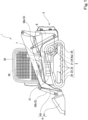
- a working machine 1 includes at least one traveling device 2 and a machine body 3 supported by the traveling device 2. Additionally, the working machine 1 includes a working device 4 for performing predetermined work, and a hydraulic system 5 (see FIG. 2 ) including actuators 50a and 50b that actuate the working device 4, and a hydraulic pump 51 that supplies a hydraulic fluid to the actuators 50a and 50b. Further, the working machine 1 includes at least one of electric devices 6a, 6b, and 6c (see FIGS. 1 to 3 ), and a power generator 7 that generates electric power to be directly or indirectly supplied to the electric devices 6a, 6b, and 6c. Accordingly, the working machine 1 according to the present embodiment includes an internal combustion engine 8 that drives the power generator 7.
- the working machine 1 since the working machine 1 according to the present embodiment includes the electric devices 6a, 6b, and 6c and the power generator 7, the working machine 1 includes a first cooling system 10 that causes a first cooling medium A to circulate therethrough to cool the electric devices 6a, 6b, and 6c, and a second cooling system 11 that causes a second cooling medium B to circulate therethrough to cool the power generator 7.
- the traveling device 2 is disposed on each of both sides (both left and right sides) of the machine body 3 in a direction (hereinafter referred to as a width direction) orthogonal to a straight traveling direction (a direction in which the machine body 3 travels forward and backward straight: hereinafter referred to as a front-rear direction). That is, the working machine 1 includes a pair of traveling devices 2 coupled to the machine body 3, and the pair of traveling devices 2 are disposed on both left and right sides (symmetrically) with the machine body 3 interposed therebetween.
- each of the pair of traveling devices 2 includes at least one idler 20, a driving wheel 21, a plurality of rollers 22, an endless annular crawler belt 23, and a driving motor 24.
- Each of the pair of traveling devices 2 includes a pair of idlers 20.
- the pair of idlers 20 are disposed at an interval in the front-rear direction.
- Each of the pair of idlers 20 is rotatable about an axis extending in the width direction.
- Each of the plurality of rollers 22 is rotatable about an axis extending in the width direction, similarly to the idler 20.
- the plurality of rollers 22 are disposed between the pair of idlers 20 at intervals in the front-rear direction.
- the driving wheel 21 is disposed between the pair of idlers 20.
- the driving wheel 21 is disposed higher than the plurality of rollers 22 between the pair of idlers 20.
- the driving wheel 21 is rotatable about an axis extending in the width direction.
- the driving wheel 21 has a plurality of engagement teeth on the outer periphery thereof, which engage with the crawler belt 23.
- the driving wheel 21 is driven to rotate about the axis by receiving drive from the driving motor 24 that is a drive source.
- the driving motor 24 is an electric motor as the electric device 6a.
- the driving motor 24 is a three-phase AC synchronous motor including one or more permanent magnets.
- the driving motor 24 (6a) may be another type synchronous motor, and may be an AC motor or a DC motor.
- the driving motor 24 (6a) includes a housing and a motor main body housed in the housing.
- the driving motor 24 (6a) is a liquid-cooled motor, and includes a passage through which the first cooling medium A flows as illustrated in FIG. 2 .
- the passage includes a start end (IN) serving as an inlet for the first cooling medium A and a terminal end (OUT) serving as an outlet for the first cooling medium A.
- the inlet (IN) and the outlet (OUT) are configured to be connectable to a pipe constituting the passage through which the first cooling medium A flows.
- the passage of the driving motor 24 is constituted by a cavity formed in a peripheral wall of the housing or a cavity formed in a water jacket disposed inside or outside the housing.
- the motor main body includes a rotatable rotor including an output shaft axially supported by the housing, and a stator that generates a force for rotating the rotor.
- the output shaft of the driving motor 24 (6a) directly or indirectly transmits a rotational force to the driving wheel 21. That is, the output shaft of the driving motor 24 (6a) is coupled to the driving wheel 21 or is operatively coupled to the driving wheel 21 via a drive transmission mechanism such as a speed reducer. Thus, the driving wheel 21 rotates by drive of the driving motor 24 (6a).
- the crawler belt 23 is wound around the idlers 20, the driving wheel 21, and the rollers 22.
- the inner periphery of the crawler belt 23 is engaged with the outer periphery (engagement teeth) of the driving wheel 21.
- a rotational torque of the driving wheel 21 is transmitted to the crawler belt 23 via the engagement teeth correspondingly. That is, the crawler belt 23 rotates around the pair of idlers 20, the plurality of rollers 22, and the driving wheel 21.
- the driving motor 24 is an electric motor that is the electric device 6a. Accordingly, as illustrated in FIGS. 2 and 3 , the working machine 1 includes an inverter (hereinafter referred to as a motor inverter) 25 that is the electric device 6b.
- the motor inverter 25 (6b) performs rotational control on the driving motor 24.
- the motor inverter 25 (6b) is a liquid-cooled inverter.
- the motor inverter 25 (6b) includes electric components such as a power module (Insulated Gate Bipolar Transistor (IGBT), Intelligent Power Module (IPM), Metal-Oxide-Semiconductor Field-Effect Transistor (MOSFET)), an electrolytic capacitor, a reactor, and the like, and a heat sink that cools these electric components.
- the heat sink is a liquid-cooled heat sink, and includes an internal passage through which the first cooling medium A flows as illustrated in FIG. 2 .
- the internal passage includes a start end (IN) serving as an inlet for the first cooling medium A and a terminal end (OUT) serving as an outlet for the first cooling medium A.
- the inlet (IN) and the outlet (OUT) are configured to be connectable to a pipe constituting the passage through which the first cooling medium A flows.
- the working machine 1 is a ride-on working machine. Accordingly, a cabin 30 is mounted on the machine body 3. Note that, in addition to an operator's seat DS on which an operator is seated, a steering wheel for steering, an operation unit for performing various operations, and the like are provided in the cabin 30.
- the working device 4 includes at least one boom 40 coupled to the machine body 3, and a working tool (attachment) 41 coupled to the boom 40 and having a predetermined function.
- the working machine 1 is a track loader (compact track loader). That is, the working device 4 is a loader device that performs loading work as the predetermined work.
- the at least one boom 40 includes a pair of booms 40 provided at an interval in the width direction. That is, the pair of booms 40 are coupled to the machine body 3 at an interval in the width direction. Specifically, one of the pair of booms 40 is disposed leftward of the machine body 3. In contrast, another of the pair of booms 40 is disposed rightward of the machine body 3. Each of the pair of booms 40 has a proximal end portion and a distal end portion opposite to the proximal end portion. The proximal end portion of each of the pair of booms 40 is coupled to the machine body 3 via a shaft extending in the width direction. Thus, the pair of booms 40 can swing (rotate) about the shaft (proximal end portions). The pair of booms 40 are coupled to each other by a coupling body between the proximal end portions and a coupling body between the distal end portions.
- the working tool 41 is a bucket.
- the working tool (bucket) 41 is coupled to the respective distal end portions of the pair of booms 40 so as to be rotatable about an axis extending in the width direction.
- the working machine 1 includes the actuators 50a and 50b that actuate the working device (loader device) 4.
- the actuators of the working machine 1 according to the present embodiment include at least one raising/lowering cylinder 50a (in the present embodiment, a pair of raising/lowering cylinders 50a as illustrated in FIG. 2 ) that raises/lowers the pair of booms 40 and at least one swinging cylinder 50b (in the present embodiment, a pair of swinging cylinders 50b as illustrated in FIG. 2 ) that swings the working tool (bucket) 41.
- Each of the raising/lowering cylinder 50a and the swinging cylinder 50b is a hydraulic cylinder that extends/contracts by supply/recovery of a hydraulic fluid.
- the hydraulic cylinders 50a and 50b each extend in one direction and each have one end portion and another end portion opposite to the one end portion in the one direction.
- the hydraulic cylinders 50a and 50b each include a tube-shaped cylinder main body extending in the one direction and having a proximal end and a distal end in the one direction, and a piston rod including a piston at one end portion.
- the piston is mounted in the cylinder main body so as to be movable in the one direction.
- a portion of the piston rod near another end portion of the piston rod protrudes from the distal end of the cylinder main body.
- a proximal end portion of the cylinder main body serves as the one end portion of the hydraulic cylinder
- the other end portion of the piston rod serves as the other end portion of the hydraulic cylinder.
- the at least one raising/lowering cylinder (hydraulic cylinder) 50a (e.g., the pair of raising/lowering cylinders 50a) is coupled at the one end portion thereof (the proximal end portion of the cylinder main body) to the machine body 3 so as to be rotatable about an axis extending in the width direction, and is coupled at the other end portion thereof (the other end portion of the piston rod) to the booms 40 so as to be rotatable about an axis extending in the width direction.
- the at least one raising/lowering cylinder 50a extends/contracts in the one direction, the pair of booms 40 rotate about the proximal end portions thereof, and the distal end portions of the pair of booms 40 are raised/lowered.
- the at least one swinging cylinder (hydraulic cylinder) 50b (e.g., the pair of raising/lowering cylinders 50a) is coupled at the one end portion thereof (the proximal end portion of the cylinder main body) to the booms 40 so as to be rotatable about an axis extending in the width direction, and is coupled at the other end portion thereof (the other end portion of the piston rod) to the working tool (bucket) 41 so as to be rotatable about an axis extending in the width direction.
- the bucket 41 rotates about the distal end portions of the booms 40 to change its posture. That is, the bucket 41 performs shoveling and dumping by swinging.
- the working machine 1 of the present embodiment is configured such that the working tool 41 can be exchanged from the bucket to another working tool, and configured to perform various types of work other than excavation work and loading work (or another excavation work). That is, the bucket 41 is attachable/detachable to/from the distal end portions of the booms 40, and a working tool 41 other than the bucket 41 is also attachable/detachable to/from the distal end portions of the booms 40.
- the bucket 41 can be detached from the working machine 1, and a hydraulic attachment as another working tool 41 can be attached to the distal end portions of the booms 40.
- the hydraulic attachment means a hydraulically driven working tool (attachment) 41 including a hydraulic actuator 50c (see FIG.
- the hydraulic attachment such as a hydraulic motor or a hydraulic cylinder.
- the hydraulic attachment include a hydraulic crusher, a hydraulic breaker, an angle broom, an earth auger, a pallet fork, a sweeper, a mower, a snow blower, and the like.
- a diesel engine is employed as the internal combustion engine 8.
- the internal combustion engine 8 is a water-cooled engine, and includes therein a passage through which a third cooling medium C flows as illustrated in FIG. 2 . Accordingly, the passage of the internal combustion engine 8 includes an inlet (IN) to which the third cooling medium C flows in and an outlet (OUT) from which the third cooling medium C flows out.
- the internal combustion engine 8 is supported by the machine body 3 via a vibration isolation mechanism. In the present embodiment, the internal combustion engine 8 is disposed in a rear portion of the machine body 3 (see FIG. 1 ).
- the power generator 7 generates electric power by receiving drive from the internal combustion engine 8. Accordingly, as illustrated in FIG. 3 , the working machine 1 includes a battery 70 that stores the electric power generated by the power generator 7 and supplies the stored electric power to the electric devices 6a, 6b, and 6c and the like. Note that the battery 70 is connected to a plurality of electric devices (including a first pump 103, a second pump 110, a third pump 121, a throttle valve 506, a cooling fan 104, a control valve unit 53, and the like, which will be described later, in addition to the driving motor 24 (6a), the motor inverter 25 (6b), and a power generator inverter 71 (6c)) mounted on the working machine 1, and supplies the electric power also to these electric devices.
- a first pump 103 including a first pump 103, a second pump 110, a third pump 121, a throttle valve 506, a cooling fan 104, a control valve unit 53, and the like, which will be described later, in addition to the driving motor 24
- the power generator 7 also functions as an electric motor that drives the hydraulic pump 51. That is, the power generator 7 according to the present embodiment is a motor/generator having a function as an electric motor that drives the hydraulic pump 51 by receiving supply of the electric power from the battery 70, and a function as the power generator 7 (generator).
- the power generator (motor/generator) 7 is a three-phase AC synchronous motor including one or more permanent magnets.
- the power generator (motor/generator) 7 includes a housing fixed to the internal combustion engine 8 and a motor main body housed in the housing.
- the motor main body includes a rotatable rotor and a stator that generates a force for rotating the rotor.
- the power generator (motor/generator) 7 is supported by the machine body 3 via a vibration isolation mechanism.
- the power generator (motor/generator) 7 is fixed to a front portion of the internal combustion engine 8 (see FIG. 1 ).
- the power generator (motor/generator) 7 is a liquid-cooled power generator, and includes a passage through which the second cooling medium B flows as illustrated in FIG. 2 .
- the passage includes a start end (IN) serving as an inlet for the second cooling medium B and a terminal end (OUT) serving as an outlet for the second cooling medium B.
- the inlet (IN) and the outlet (OUT) are configured to be connectable to a pipe constituting the passage through which the second cooling medium B flows.
- the passage of the power generator (motor/generator) 7 is constituted by a cavity formed in a peripheral wall of the housing or a cavity formed in a water jacket disposed inside or outside the housing, similarly to the driving motor 24 (6a).
- the power generator 7 is the motor/generator.
- the working machine 1 includes the power generator inverter 71 that is the electric device 6c.
- the power generator inverter 71 (6c) is a liquid-cooled invertor.
- the power generator inverter 71 (6c) includes electric components such as a power module (IGBT, IPM, MOSFET), an electrolytic capacitor, a reactor, and the like, and a heat sink that cools these electric components.
- the heat sink is a liquid-cooled heat sink, and includes an internal passage through which the first cooling medium A flows as illustrated in FIG. 2 .
- the internal passage includes a start end (IN) serving as an inlet for the first cooling medium A and a terminal end (OUT) serving as an outlet for the first cooling medium A.
- the inlet (IN) and the outlet (OUT) are configured to be connectable to a pipe constituting the passage through which the first cooling medium A flows.
- the working machine 1 includes the driving motor 24 (6a), the motor inverter 25 (6b), and the power generator inverter 71 (6c) as the electric devices, each of which is a liquid-cooled electric device.
- the working machine 1 includes a controller 9 that performs control relating to the entire working machine 1, and the electric devices 6a, 6b, and 6c are actuated based on instructions from the controller 9.
- controller 9 is also connected to electric devices (electric devices such as the first pump 103, the second pump 110, the third pump 121, the throttle valve 506, the cooling fan 104, and the control valve unit 53) other than the driving motor 24 (6a), the motor inverter 25 (6b), and the power generator inverter 71 (6c), and also controls these electric devices.
- electric devices electric devices such as the first pump 103, the second pump 110, the third pump 121, the throttle valve 506, the cooling fan 104, and the control valve unit 53
- the hydraulic system 5 includes the hydraulic pump 51 as described above. Additionally, as illustrated in FIG. 2 , the hydraulic system 5 includes a hydraulic fluid tank 52 that stores a hydraulic fluid S, a primary system 5A that connects the actuators 50a and 50b and the hydraulic fluid tank 52 via the hydraulic pump 51 and supplies the hydraulic fluid S stored in the hydraulic fluid tank 52 to the actuators 50a and 50b by drive of the hydraulic pump 51, and a secondary system 5B that connects the actuators 50a and 50b and the hydraulic fluid tank 52 and returns the hydraulic fluid S from the actuators 50a and 50b to the hydraulic fluid tank 52. Additionally, the hydraulic system 5 includes the control valve unit 53 that controls the flow of the hydraulic fluid S.
- the power of the internal combustion engine 8 and the power of the power generator (motor/generator) 7 are transmitted to the hydraulic pump 51 selectively or in combination. That is, the hydraulic pump 51 is driven by at least one of the internal combustion engine 8 and the power generator (motor/generator) 7.
- the hydraulic pump 51 is a multiple hydraulic pump.
- the hydraulic pump 51 is a multiple hydraulic pump including a main pump, a sub pump, and a pilot pump, which are disposed in series.
- FIG. 2 illustrates a system connected to the main pump, as the hydraulic system 5.
- the sub pump is a hydraulic pump for increasing the amount of the hydraulic fluid S to be supplied to the actuators 50a and 50b that are actuated by the main pump.
- the pilot pump is a hydraulic pump for supplying the hydraulic fluid S for pilot signals to control valves that control the actuators 50a and 50b that are actuated by the main pump.
- the sub pump and the pilot pump are constituted by, for example, fixed displacement gear pumps.
- the primary system 5A is a system that connects the hydraulic fluid tank 52 and the actuators 50a and 50b, and is a system that supplies the hydraulic fluid in the hydraulic fluid tank 52 to the actuators 50a and 50b.
- the primary system 5A includes a first supply fluid passage 500 that connects a suction port (a port for sucking the hydraulic fluid S) of the hydraulic pump 51 (main pump) and the hydraulic fluid tank 52, a second supply fluid passage 501 that connects a delivery port (a port for delivering the hydraulic fluid S) of the hydraulic pump 51 (main pump) and the control valve unit 53, and a third supply fluid passage 502 that connects the control valve unit 53 and the actuators 50a and 50b.
- the hydraulic pump 51 main pump
- the first supply fluid passage 500, the second supply fluid passage 501, the third supply fluid passage 502, the first return fluid passage 503, and the second return fluid passage 504 are constituted by pipes.
- a first heat exchanger 100a of the first cooling system 10, which will be described later, is interposed in the secondary system 5B.
- the first heat exchanger 100a is interposed in the second return fluid passage 504 of the secondary system 5B.
- a passage through which the hydraulic fluid S flows and that constitutes a portion of the second return fluid passage 504 is formed in the first heat exchanger 100a.
- the hydraulic system 5 (secondary system 5B) includes a bypass 505 that connects a first position P1 located upstream of the first heat exchanger 100a on the second return fluid passage 504 and a second position P2 located downstream of the first heat exchanger 100a.
- the bypass 505 includes the throttle valve 506 that adjusts the flow rate of the hydraulic fluid S.
- the control valve unit 53 includes a plurality of control valves 53a, 53b, and 53c.
- the control valve unit 53 illustrated in FIG. 2 includes three control valves 53a, 53b, and 53c. Note that, in the following description, the three control valves 53a, 53b, and 53c are referred to as a first control valve 53a, a second control valve 53b, and a third control valve 53c.
- the first control valve 53a is a valve that controls the raising/lowering cylinder (hydraulic actuator) 50a.
- the second control valve 53b is a control valve that controls the swinging cylinder (hydraulic actuator) 50b.
- the third control valve 53c is a valve that controls the actuator 50c provided in a hydraulic attachment.
- the hydraulic attachment is a hydraulically driven working tool 41.
- the actuator 50c of the hydraulic attachment is connected to the third control valve 53c via a connecting member 54.
- the working machine 1 includes a circulation passage through which a medium circulates, the medium which is to exchange heat with a heat source and to take heat of the heat source through heat exchange.
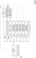
- the working machine 1 includes the first cooling system 10 that causes the first cooling medium A to circulate therethrough to cool the electric devices 6a, 6b, and 6c, and the second cooling system 11 that causes the second cooling medium B to circulate therethrough to cool the power generator 7.
- the working machine 1 (cooler system) includes the internal combustion engine 8, and hence includes a third cooling system 12 that causes the third cooling medium C to circulate therethrough to cool the internal combustion engine 8.
- the first cooling system 10 includes the first heat exchanger 100a that exchanges heat between the hydraulic fluid S flowing through the hydraulic system 5 and the first cooling medium A to cool the hydraulic fluid S, a second heat exchanger 100b that exchanges heat between the first cooling medium A and the second cooling medium B to cool the second cooling medium B, and a third heat exchanger 100c that exchanges heat between the first cooling medium A and outside air to cool the first cooling medium A so that a temperature of the first cooling medium A becomes lower than temperatures before the heat exchange of the hydraulic fluid S and the second cooling medium B.
- the first cooling system 10 includes a cooling medium tank 102 that stores the first cooling medium A, and the pump (hereinafter, referred to as a first pump) 103 that sucks and delivers the first cooling medium A in the cooling medium tank 102.
- a first pump the pump that sucks and delivers the first cooling medium A in the cooling medium tank 102.
- the first heat exchanger 100a and the second heat exchanger 100b are liquid-cooled heat exchangers.
- plate-shaped heat exchangers are employed as the liquid-cooled heat exchangers.
- the plate-shaped heat exchangers 100a and 100b each include a plurality of heat transfer plates 101.
- the plurality of heat transfer plates 101 are stacked in a state of facing each other, and a first passage R1 through which a heat exchanging medium A flows and a second passage R2 through which a heat exchanged medium B or S flows are alternately formed with each of the heat transfer plates 101 as a boundary.
- each of the plurality of heat transfer plates 101 is formed by press-molding a metal plate, and a plurality of concave threads and convex threads are formed on a front surface and a back surface.
- the concave threads and the convex threads are alternately arranged in a direction orthogonal to a direction in which the concave threads (convex threads) extend.
- the heat transfer plate 101 is formed by press-molding a metal plate.
- the concave threads on the front surface constitute the convex threads on the back surface
- the convex threads on the front surface constitute the concave threads on the back surface.
- each of the plurality of stacked heat transfer plates 101 meet the convex threads of the adjacent heat transfer plates 101 in a crossing manner.
- the concave threads of the adjacent heat transfer plates 101 form the first passage R1 or the second passage R2.
- Each of the plurality of heat transfer plates 101 has openings at four corners. In a state in which the plurality of heat transfer plates 101 are stacked, each of the four openings of the heat transfer plates 101 is continuous in a stacking direction of the heat transfer plates 101, and forms a passage that communicates with the first passage R1 or the second passage R2.
- two openings of the four openings constitute two passages Ra1 and Ra2 connected to the first passage R1
- the remaining two openings constitute two passages Rb1 and Rb2 connected to the second passage R2.
- One passage Ra1 of the two passages Ra1 and Ra2 connected to the first passage R1 is an inflow passage through which the heat exchanging medium A flows in
- another passage Ra2 is an outflow passage through which the heat exchanging medium A, which has passed through the first passage R1, flows out.
- one end opening of the inflow passage Ra1 constitutes an inlet (IN) to which the heat exchanging medium A flows in
- one end opening of the outflow passage Ra2 (an opening of the outermost heat transfer plate 101) constitutes an outlet (OUT) from which the heat exchanging medium A flows out.
- one passage Rb1 of the two passages Rb1 and Rb2 connected to the second passage R2 is an inflow passage through which the heat exchanged medium S or B flows in
- another passage Rb2 is an outflow passage through which the heat exchanged medium S or B, which has passed through the second passage R2, flows out.
- one end opening of the inflow passage Rb1 constitutes an inlet (IN) to which the heat exchanged medium S or B flows in
- one end opening of the outflow passage Rb2 constitutes an outlet (OUT) from which the heat exchanged medium S or B flows out.
- the first cooling medium A is caused to flow through the first passage R1 as the heat exchanging medium
- the second cooling medium B is caused to flow through the second passage R2 as the heat exchanged medium.
- the third cooling system 12 includes a fourth heat exchanger 120 that exchanges heat between the third cooling medium C and outside air and is provided in parallel with the third heat exchanger 100c. Accordingly, at least one of the first cooling system 10 and the third cooling system 12 includes the cooling fan 104 that is arranged beside the third heat exchanger 100c and the fourth heat exchanger 120. That is, at least one of the first cooling system 10 and the third cooling system 12 includes the cooling fan 104 that sends outside air toward the third heat exchanger 100c and the fourth heat exchanger 120.
- the pipe body forms the passage as a pipeline.
- the pipe body (passage) includes a start end and a terminal end, the start end constitutes an inlet to which the cooling medium (first cooling medium A, third cooling medium C) flows in, and the terminal end constitutes an outlet from which the cooling medium (first cooling medium A, third cooling medium C) flows out.
- the inlet and the outlet are connected to a pipe that constitutes the passage.
- the lengths of the passages (pipe bodies) of the radiators 100c and 120 are set in accordance with heat exchange capacities.
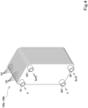
- the passages (pipe bodies) are disposed in a meandering manner in order to dispose the passages (pipe bodies) having necessary lengths in a predetermined space. That is, the passages (pipe bodies) of the radiators 100c and 120 each have a plurality of straight portions formed in a straight-line shape and a U-shaped turn portion that connects the adjacent straight portions to each other. The straight portions and the turn portion are alternately connected to form the passage having the necessary length.
- the pipe bodies are arranged so as to penetrate a plurality of fins arranged in a direction in which the straight portions extend.
- the plurality of fins are disposed at intervals in a predetermined direction (the direction in which the straight portions extend).
- a gap air passage through which outside air passes in a direction orthogonal to the predetermined direction is formed between the adjacent fins.
- FIG. 6 illustrates only fins appearing on an outer surface (appearance).
- the cooling fan 104 is an electric fan that is driven by an electric motor M, and is provided in the first cooling system 10 in the present embodiment (see FIG. 2 ).
- Examples of the cooling fan 104 include a push-in fan that pushes outside air and a suction fan that sucks outside air.
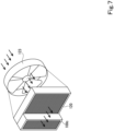
- a suction fan is employed as the cooling fan 104, and the cooling fan 104 is disposed inward of the third heat exchanger 100c and the fourth heat exchanger 120 in the machine body 3 in a state in which a suction direction of outside air coincides with airflow directions of the third heat exchanger 100c and the fourth heat exchanger 120.
- the cooling fan 104 sucks outside air and sends the outside air toward the third heat exchanger 100c and the fourth heat exchanger 120 provided in parallel (sends outside air outside the machine body 3 toward the third heat exchanger 100c and the fourth heat exchanger 120).
- the sent outside air passes through the third heat exchanger 100c and the fourth heat exchanger 120 (between the fins), and each of the first cooling medium A and the third cooling medium C exchanges heat with the outside air and is cooled.
- the first pump 103 is an electric pump, and has a suction port for sucking the first cooling medium A, and a delivery port for delivering the first cooling medium A sucked into the suction port.
- the first cooling system 10 includes a suction-side pipe 105 that connects the cooling medium tank 102 and the suction port of the first pump 103 and through which the first cooling medium A flows from the cooling medium tank 102 to the first pump 103 (through which the first cooling medium A is sucked), and a delivery-side pipe 106 that connects the delivery port of the first pump 103 and the cooling medium tank 102 and through which the first cooling medium A delivered by the first pump 103 flows and the first cooling medium A returns to the cooling medium tank 102.
- the first cooling system 10 includes the first heat exchanger 100a, the second heat exchanger 100b, and the third heat exchanger 100c.
- the first heat exchanger 100a, the second heat exchanger 100b, and the third heat exchanger 100c are disposed on the delivery-side pipe 106 of the first cooling system 10.
- the third heat exchanger 100c, the second heat exchanger 100b, and the first heat exchanger 100a are disposed in this order from an upstream side to a downstream side of the delivery-side pipe 106.
- the third heat exchanger 100c is disposed most upstream in a flow direction of the first cooling medium A
- the first heat exchanger 100a is disposed most downstream in the flow direction of the first cooling medium A
- the second heat exchanger 100b is disposed between the first heat exchanger 100a and the third heat exchanger 100c.
- the delivery-side pipe 106 includes a first delivery-side pipe 106a that connects the delivery port of the first pump 103 and an inlet (IN) for the first cooling medium (heat exchanging medium) A of the third heat exchanger 100c, a second delivery-side pipe 106b that connects an outlet (OUT) for the first cooling medium (heat exchanging medium) A of the third heat exchanger 100c and an inlet (IN) for the first cooling medium (heat exchanging medium) A of the second heat exchanger 100b, a third delivery-side pipe 106c that connects an outlet (OUT) for the first cooling medium (heat exchanging medium) A of the second heat exchanger 100b and an inlet (IN) for the first cooling medium (heat exchanging medium) A of the first heat exchanger 100a, and a fourth delivery-side pipe 106d that connects an outlet (OUT) for the first cooling medium (heat exchanging medium) A of the first heat exchanger 100a and the cooling medium tank 102.
- An inlet (IN) for the heat exchanged medium (hydraulic fluid S) of the first heat exchanger 100a is connected to the control valve unit 53 (upstream) side of the second return fluid passage 504, and an outlet (OUT) for the heat exchanged medium (hydraulic fluid S) of the first heat exchanger 100a is connected to the hydraulic fluid tank 52 (downstream) side of the second return fluid passage 504.
- a passage (inflow passage Rb1, second passage R2, outflow passage Rb2: see FIG. 5 ) through which the hydraulic fluid (heat exchanged medium) S flows of the first heat exchanger 100a constitutes a portion of the second return fluid passage 504.
- the plurality of electric devices 6a, 6b, and 6c are disposed on the first cooling system 10.
- the plurality of electric devices 6a, 6b, and 6c are disposed on the delivery-side pipe 106 of the first cooling system 10. More specifically, the plurality of electric devices 6a, 6b, and 6c are disposed on the second delivery-side pipe 106b of the delivery-side pipe 106.
- the plurality of electric devices 6a, 6b, and 6c are disposed in ascending order of heat resistance and heat generation temperature during operation from the upstream side to the downstream side in the flow direction of the first cooling medium A.
- the power generator inverter 71 (6c), the motor inverter 25 (6b), and the driving motor 24 (6a) are disposed in this order from the upstream side to the downstream side of the first cooling system 10.
- the inverters 71 (6c) and 25 (6b) have lower heat resistances than the heat resistance of another electric device 6a (in the present embodiment, the driving motor 24 (6a)). Hence the inverters 71 (6c) and 25 (6b) are disposed upstream of the other electric device 6a.
- the power generator inverter 71 (6c) has specifications with a lower heat resistance than the heat resistance of the motor inverter 25 (6b). Hence the power generator inverter 71 (6c) is disposed upstream of the motor inverter 25 (6b).
- the second delivery-side pipe 106b includes a first connection pipe 107a that connects the outlet (OUT) for the first cooling medium (heat exchanging medium) A of the third heat exchanger 100c and the inlet (IN) of the power generator inverter 71 (6c), a second connection pipe 107b that connects the outlet (OUT) of the power generator inverter 71 (6c) and the inlet (IN) of the motor inverter 25 (6b), a third connection pipe 107c that connects the outlet (OUT) of the motor inverter 25 (6b) and the inlet (IN) of the driving motor 24 (6a), and a fourth connection pipe 107d that connects the outlet (OUT) of the driving motor 24 (6a) and the inlet (IN) for the first cooling medium (heat exchanging medium) A of the second heat exchanger 100b.
- the second cooling system 11 includes an annular passage (circulation passage) through which the second cooling medium B flows.
- the pump (hereinafter, referred to as a second pump) 110 for delivering (pumping) the second cooling medium B, the second heat exchanger 100b, and the power generator 7 are disposed on the circulation passage of the second cooling system 11.
- the second pump 110 is an electric pump, and has a suction port for sucking the second cooling medium B and a delivery port for delivering the second cooling medium B.
- the second cooling system 11 includes a first pipe 111a that connects the delivery port of the second pump 110 and an inlet (IN) for the second cooling medium (heat exchanged medium) B of the second heat exchanger 100b, a second pipe 111b that connects an outlet (OUT) for the second cooling medium (heat exchanged medium) B of the second heat exchanger 100b and the inlet (IN) of the power generator 7, and a third pipe 111c that connects the outlet (OUT) of the power generator 7 and the suction port of the second pump 110.
- the second cooling system 11 uses the second passage R2 of the second heat exchanger 100b and the internal passage of the power generator 7 as a portion of the circulation passage, and causes the second cooling medium B to circulate therethrough while causing the second cooling medium B to pass through the second heat exchanger 100b and the power generator 7 by the second pump 110 being driven.
- the second cooling medium B is a liquid having a specific heat smaller than the specific heat of the first cooling medium A and a boiling point higher than the boiling point of the first cooling medium A.
- the first cooling medium (heat exchanging medium) A flowing through the first cooling system 10 is water.
- the second cooling medium (heat exchanged media) B flowing through the second cooling system 11 is oil.
- the hydraulic fluid S flowing through the hydraulic system 5 is the heat exchanged medium flowing through the second passage R2 of the first heat exchanger 100a.
- the first heat exchanger 100a exchanges heat between the water as the first cooling medium (heat exchanging medium) A and the oil (hydraulic fluid) S as the heat exchanged medium
- the second heat exchanger 100b exchanges heat between the water as the first cooling medium (heat exchanging medium) A and the oil as the second cooling medium (heat exchanged medium) B.
- an oil pump capable of pumping oil having a viscosity higher than the viscosity of water is employed as the second pump 110 of the second cooling system 11.
- the third cooling system 12 includes an annular passage (circulation passage) through which the third cooling medium C flows.
- the pump (hereinafter, referred to as a third pump) 121 for delivering (pumping) the third cooling medium C and the fourth heat exchanger 120 are disposed on the circulation passage of the third cooling system 12.
- the third pump 121 is an electric pump, and has a suction port for sucking the third cooling medium C and a delivery port for delivering the third cooling medium C.
- the third cooling system 12 includes a first passage pipe 122a that connects the delivery port of the third pump 121 and an inlet (IN) of the fourth heat exchanger 120, a second passage pipe 122b that connects an outlet (OUT) of the fourth heat exchanger 120 and the inlet (IN) of the internal combustion engine 8, and a third passage pipe 122c that connects the outlet (OUT) of the internal combustion engine 8 and the suction port of the third pump 121.
- the third cooling system 12 uses the passage (pipeline) of the fourth heat exchanger 120 and the passage of the internal combustion engine 8 as a portion of the circulation passage, and causes the third cooling medium C to circulate therethrough while causing the third cooling medium C to pass through the fourth heat exchanger 120 and the internal combustion engine 8 by the third pump 121 being driven.
- the third cooling medium C is water (or antifreeze).
- the fourth heat exchanger (radiator) 120 is disposed so as to overlap the third heat exchanger (radiator) 100c in the airflow directions of outside air. That is, the third heat exchanger (radiator) 100c and the fourth heat exchanger (radiator) 120 are gas-liquid heat exchangers, and hence are disposed so that the outside air forcibly sent by the cooling fan 104 can pass therethrough in the same direction.
- the working machine 1 is as described above, and when the traveling device 2 performs traveling, the driving motor 24 (6a) is driven, and hence the temperatures of the driving motor 24 (6a) and the motor inverter 25 (6b) increase in accordance with the load of the driving motor 24 (6a). Also, when the working device 4 performs work, the internal combustion engine 8 is driven, the power generator 7 is driven, and the hydraulic pump 51 is driven via the power generator 7. Then, the temperature of the internal combustion engine 8 increases in accordance with the load, and the temperatures of the power generator 7 and the power generator inverter 71 (6c) increase in accordance with the power generation amount. Also, in the hydraulic system 5, the temperature of the hydraulic fluid S increases in accordance with the load of the hydraulic pump 51 (actions (loads) of the actuators 50a and 50b).
- the working machine 1 drives the first pump 103 of the first cooling system 10, the second pump 110 of the second cooling system 11, and the third pump 121 of the third cooling system 12.
- the first cooling medium A water in the cooling medium tank 102 is sucked by the first pump 103 and is sent to the downstream side.
- the first cooling medium A delivered from the first pump 103 exchanges heat with outside air by air forcibly sent by the cooling fan 104 and is cooled to a set temperature when passing through the third heat exchanger 100c. Then, the first cooling medium A cooled to the set temperature through the heat exchange with the outside air is sent to the downstream side, and passes (flows) through the power generator inverter 71 (6c), the motor inverter 25 (6b), and the driving motor 24 (6a) in this order.
- the first cooling medium A exchanges heat with the power generator inverter 71 (6c), the motor inverter 25 (6b), and the driving motor 24 (6a), which are in heat generating states, and cools these components.
- a temperature increase rate (increased temperature) during operation becomes higher in the order of the power generator inverter 71 (6c), the motor inverter 25 (6b), and the driving motor 24 (6a).
- the first cooling medium A cools the electric devices 6a, 6b, and 6c in ascending order of cooling temperature, and minimizes the temperature increase of the first cooling medium A as a result of cooling the plurality of electric devices 6a, 6b, and 6c.
- the first cooling medium A flows to the downstream side (toward the second heat exchanger 100b) while maintaining a temperature in a state in which cooling is possible even on the downstream side (a temperature in a state in which a temperature range necessary for cooling on the downstream side remains) without reaching the boiling point.
- the second pump 110 causes the second cooling medium (oil) B to circulate (flow) through the circulation passage, and when the second cooling medium (oil) B passes through the power generator 7, the second cooling medium B exchanges heat with the power generator 7 in a heat generating state to cool the power generator 7.
- the second cooling medium B which has exchanged heat with the power generator 7, passes through the second pump 110 and passes through the second heat exchanger 100b. At this time, the second cooling medium B passing through the second heat exchanger 100b exchanges heat with the first cooling medium A of the first cooling system 10 and is cooled.
- the temperature of the second cooling medium B increases through the heat exchange with the power generator 7; however, the temperature of the second cooling medium B is prevented from becoming lower than the temperature of the first cooling medium A because the second cooling medium B is the liquid having the specific heat smaller than the specific heat of the first cooling medium A and the boiling point higher than the boiling point of the first cooling medium A. That is, in the state in which heat is exchanged in the second heat exchanger 100b, the temperature of the first cooling medium A is prevented from becoming higher than the temperature of the second cooling medium B, and the first cooling medium A takes heat from the second cooling medium B to cool the second cooling medium B in the second heat exchanger 100b.
- the power generator 7 is stably cooled.
- the first cooling medium A which has passed through the second heat exchanger 100b, flows to the downstream side (toward the first heat exchanger 100a).
- the first cooling medium A exchanges heat with the hydraulic fluid S flowing through the hydraulic system 5 and passing through the first heat exchanger 100a to cool the hydraulic fluid S.
- the temperature of the hydraulic fluid S increases in accordance with the workloads (heat amounts) by the actuators 50a, 50b, and 50c; however, the hydraulic fluid S is prevented from becoming lower than the temperature of the first cooling medium A because the hydraulic fluid S is a liquid having a specific heat smaller than the specific heat of the first cooling medium A and a boiling point higher than the boiling point of the first cooling medium A similarly to the second cooling medium B.
- the temperature of the first cooling medium A is prevented from becoming higher than the temperature of the hydraulic fluid S, and the first cooling medium A takes heat from the hydraulic fluid S to cool the hydraulic fluid S in the first heat exchanger 100a.
- the working machine 1 includes the temperature sensor 507 that measures the temperature of the hydraulic fluid S in the hydraulic fluid tank 52, and the controller 9 adjusts the opening of the throttle valve 506 based on the measurement result of the temperature sensor 507 to maintain the temperature of the hydraulic fluid S at the appropriate temperature.
- the throttle valve 506 is an electric fan whose opening is adjusted by driving an electric motor M (see FIG. 2 ).
- the hydraulic system 5 includes the bypass 505 that connects the first position P1 located upstream of the first heat exchanger 100a and the second position P2 located downstream of the first heat exchanger 100a, and the throttle valve 506 is provided in the bypass 505. Accordingly, opening/closing the throttle valve 506 brings the hydraulic fluid S flowing from the upstream side (the control valve unit 53 side) into a state in which the hydraulic fluid S flows through only the second heat exchanger 100b and a state in which the hydraulic fluid S flows through the second heat exchanger 100b and the bypass 505. Also, adjusting the opening of the throttle valve 506 can change the ratio between the flow rate of the hydraulic fluid S flowing through the second heat exchanger 100b and the flow rate of the hydraulic fluid S flowing through the bypass 505.
- the first cooling medium A which has exchanged heat with the hydraulic fluid S, returns to the cooling medium tank 102 in a state of having the highest temperature corresponding to the heat amounts, by which the first cooling medium A has sequentially performed cooling (the first cooling medium A has taken heat). Then, the first cooling medium A is sucked again by the first pump 103, passes through the third heat exchanger 100c, and is cooled to an initial temperature.
- the third pump 121 causes the third cooling medium C (antifreeze) to circulate (flow) through the circulation passage, and when the third cooling medium C (antifreeze) passes through the internal combustion engine 8, the third cooling medium C exchanges heat with the internal combustion engine 8 in a heat generating state to cool the internal combustion engine 8.
- the third cooling medium C which has exchanged heat with the internal combustion engine 8, passes through the third pump 121 and passes through the fourth heat exchanger 120.
- the fourth heat exchanger 120 is arranged in parallel with the third heat exchanger 100c, and hence the third cooling medium C passing through the fourth heat exchanger 120 exchanges heat with the outside air and is cooled with the air forcibly sent by the cooling fan 104 of the first cooling system 10, similarly to the first cooling medium A of the first cooling system 10.
- the third cooling medium C is caused to circulate (flow) through the circulation passage of the third cooling system 12, and hence the internal combustion engine 8 is stably cooled.
- the working device 4 (hydraulic system 5) is switched between a state in which the internal combustion engine 8 drives the hydraulic pump 51 via the power generator 7 and a state in which the power generator 7 functions as a motor by receiving supply of electric power from the battery 70 and drives the hydraulic pump 51.
- the temperature of the power generator 7 increases with the drive (load); however, is appropriately cooled with the second cooling medium B of the second cooling system 11, and the second cooling medium B is cooled with the first cooling medium A flowing through the first cooling system 10 (second heat exchanger 100b), similarly to the case where the power generator 7 is driven by the internal combustion engine 8.
- the working machine 1 can cool the hydraulic fluid S flowing through the hydraulic system 5 and the second cooling medium (oil) B flowing through the second cooling system 11 to appropriate temperatures with the first cooling medium A flowing through the first cooling system 10.
- the working machine 1 according to the present embodiment is as described above, and the present invention (a preferred embodiment thereof) provides a working machine 1 described in the following items.
- a working machine 1 comprising: a working device 4; a hydraulic system 5 including at least one actuator 50a, 50b, or 50c to actuate the working device 4, and a hydraulic pump 51 to supply a hydraulic fluid S to the actuator 50a, 50b, or 50c; at least one electric device 6a, 6b, or 6c; a power generator 7 to generate electric power to be directly or indirectly supplied to the electric device 6a, 6b, or 6c; a first cooling system 10 to cause a first cooling medium A to circulate therethrough to cool the electric device 6a, 6b, or 6c; and a second cooling system 11 to cause a second cooling medium B to circulate therethrough to cool the power generator 7, wherein the first cooling system 10 includes a first heat exchanger 100a to exchange heat between the hydraulic fluid S and the first cooling medium A to cool the hydraulic fluid S, a second heat exchanger 100b to exchange heat between the first cooling medium A and the second cooling medium B to cool the second cooling medium B, and a third heat exchanger 100c to exchange heat between
- the first cooling medium A circulating (flowing) through the first cooling system 10 exchanges heat with the outside air in the third heat exchanger 100c and hence is cooled to an appropriate temperature (a temperature at which each component can be cooled to an appropriate temperature). Accordingly, even when the temperatures of the electric devices 6a, 6b, and 6c increase (or will increase) with driving (actuation), the electric devices 6a, 6b, and 6c are cooled with the first cooling medium A, which has been heat-exchanged (cooled) in the third heat exchanger 100c, and operate at appropriate temperatures (are not overloaded).
- the temperature of the hydraulic fluid S flowing (circulating) through the hydraulic system 5 increases by work of the hydraulic pump 51 and the actuators 50a, 50b, and 50c
- the temperature of the second cooling medium B flowing (circulating) through the second cooling system 11 increases through the heat exchange with (cooling of) the power generator 7.
- the first cooling medium A flowing through the first cooling system 10 exchanges heat with the hydraulic fluid S in the first heat exchanger 100a and exchanges heat with the second cooling medium B in the second heat exchanger 100b, thereby cooling the hydraulic fluid S and the second cooling medium B to appropriate temperatures.
- the heat exchangers (first heat exchanger 100a, second heat exchanger 100b) to cool (heat-exchange) the hydraulic fluid S of the hydraulic system 5 and the second cooling medium B of the second cooling system 11 do not need to exchange heat with the outside air. That is, it is not necessary to dispose the heat exchangers at positions at which the outside air can be taken in.
- the flexibility of the arrangement of the heat exchangers increases by adjusting routing of pipes of the respective systems, and the plurality of cooling systems including the hydraulic system 5 can be made compact.
- (Item 2) The working machine 1 according to Item 1, wherein the hydraulic system 5 includes a hydraulic fluid tank 52 to store the hydraulic fluid S, a primary system 5A connecting the actuator 50a, 50b, or 50c and the hydraulic fluid tank 52 via the hydraulic pump 51, to supply the hydraulic fluid S stored in the hydraulic fluid tank 52 to the actuator 50a, 50b, or 50c by drive of the hydraulic pump 51, and a secondary system 5B connecting the actuator 50a, 50b, 50c and the hydraulic fluid tank 52, to return the hydraulic fluid S from the actuator 50a, 50b, or 50c to the hydraulic fluid tank 52, and the first heat exchanger 100a is disposed on the secondary system 5B, to exchange heat between the hydraulic fluid S flowing through the secondary system 5B and the first cooling medium A.
- the hydraulic system 5 includes a hydraulic fluid tank 52 to store the hydraulic fluid S, a primary system 5A connecting the actuator 50a, 50b, or 50c and the hydraulic fluid tank 52 via the hydraulic pump 51, to supply the hydraulic fluid S stored in the hydraulic fluid tank 52 to the actuator 50a
- the first heat exchanger 100a is disposed on the secondary system 5B through which the hydraulic fluid S having a temperature increased by the work (operation) of the hydraulic pump 51 and the actuators 50a, 50b, and 50c flows.
- the hydraulic fluid S can be cooled before the hydraulic fluid S returns to the hydraulic fluid tank 52 through the heat exchange between the hydraulic fluid S and the first cooling medium A in the first heat exchanger 100a.
- the hydraulic fluid S stored in the hydraulic fluid tank 52 can be prevented from being overheated, and the hydraulic pump 51 sucks the hydraulic fluid S at the appropriate temperature from the hydraulic fluid tank 52 and supplies the hydraulic fluid S to the actuators 50a, 50b, and 50c.
- (Item 3) The working machine 1 according to Item 2, wherein the hydraulic system 5 includes a temperature sensor 507 to measure a temperature of the hydraulic fluid S in the hydraulic fluid tank 52, and a bypass 505 connecting a first position P1 located upstream of the first heat exchanger 100a on the secondary system 5B and a second position P2 located downstream of the first heat exchanger 100a, and the bypass 505 includes a throttle valve 506 to adjust a flow rate of the hydraulic fluid S so that a measurement result of the temperature sensor 507 becomes an appropriate temperature of the hydraulic fluid S.
- the hydraulic system 5 includes a temperature sensor 507 to measure a temperature of the hydraulic fluid S in the hydraulic fluid tank 52, and a bypass 505 connecting a first position P1 located upstream of the first heat exchanger 100a on the secondary system 5B and a second position P2 located downstream of the first heat exchanger 100a, and the bypass 505 includes a throttle valve 506 to adjust a flow rate of the hydraulic fluid S so that a measurement result of the temperature sensor 507 becomes an appropriate temperature
- opening/closing the throttle valve 506 can bring the hydraulic fluid S into a state in which the hydraulic fluid S flows through only the first heat exchanger 100a and a state in which the hydraulic fluid S flows through both the first heat exchanger 100a and the bypass 505. Also, adjusting the opening of the throttle valve 506 can change the ratio between the flow rate of the hydraulic fluid S flowing through the first heat exchanger 100a and the flow rate of the hydraulic fluid S flowing through the bypass 505. That is, the ratio between the hydraulic fluid S cooled (heat-exchanged) in the first heat exchanger 100a and the hydraulic fluid S flowing through the bypass 505 can be changed.
- the temperature sensor 507 measures the temperature of the hydraulic fluid S in the hydraulic fluid tank 52, and the opening (flow rate) of the throttle valve 506 is adjusted so that the temperature becomes the appropriate temperature for the hydraulic fluid S.
- the hydraulic system 5 (actuators 50a, 50b, 50c, hydraulic pump 51) can exhibit a predetermined capacity.
- (Item 4) The working machine 1 according to any one of Items 1 to 3, wherein the at least one electric device 6a, 6b, or 6c includes a plurality of electric devices 6a, 6b, and/or 6c, and the plurality of electric devices 6a, 6b, and/or 6c are disposed on the first cooling system 10 and cooled in ascending order of heat resistance and heat generation temperature during operation from an upstream side to a downstream side in a flow direction of the first cooling medium A.
- the plurality of electric devices 6a, 6b, and 6c are disposed on the first cooling system 10 in the ascending order of the heat resistance and the heat generation temperature during the operation from the upstream side to the downstream side in the flow direction of the first cooling medium A.
- the electric device 6a, 6b, or 6c having a low heat resistance can be preferentially cooled, and occurrence of a failure of the electric device 6a, 6b, or 6c having the low heat resistance can be suppressed.
- the electric device 6a, 6b, or 6c located on a more upstream side of the first cooling system 10 generates heat at a lower heat generation temperature during operation, and hence the increase in temperature of the first cooling medium A as a result of taking heat from the electric device 6a, 6b, or 6c is small (temperature range is narrow).
- the first cooling medium A flows to the downstream side with a margin for taking heat from the electric device 6a, 6b, or 6c located on the downstream side.
- the plurality of electric devices 6a, 6b, and/or 6c are cooled with the first cooling medium A, it is possible to prevent a situation in which the electric device 6a, 6b, or 6c disposed on the downstream side cannot be cooled.
- the inverter 25 since the inverter 25 has a lower heat resistance than the heat resistance of the electric motor 24, the inverter 25 is disposed upstream of the electric motor 24 as described above, and hence the inverter 25 having the lower heat resistance can be preferentially heat-exchanged (cooled). Thus, it is possible to suppress occurrence of a failure of the inverter 25 due to overheating.
- (Item 6) The working machine 1 according to any one of Items 1 to 5, wherein the at least one electric device 6c includes a power generator inverter 71 to drive the power generator 7, and the power generator inverter 71 is disposed on the first cooling system 10.
- the power generator inverter 71 since the power generator inverter 71 has a low heat resistance similarly to the motor inverter 25, the power generator inverter 71 is disposed on the first cooling system 10, and hence it is possible to suppress occurrence of a failure due to overheating of the power generator inverter 71.
- the working machine 1 of Item 7 even when the first cooling medium A flows through the first cooling system 10 and the temperature of the first cooling medium A increases as a result of cooling the electric devices 6a, 6b, and 6c, it is possible to prevent the temperature of the first cooling medium A from exceeding the temperature of the second cooling medium B. That is, it is possible to prevent a situation in which the temperature of the first cooling medium A becomes higher than the temperature of the second cooling medium B before the first cooling medium A reaches the second heat exchanger 100b, and the second cooling medium B cannot be cooled (heat cannot be taken from the second cooling medium B).
- the first cooling medium A and the second cooling medium B are not special, and are easily handled.
- the workload (heat generation amount) of the power generator 7 is larger than the workloads (heat generation amounts) of the electric devices 6a, 6b, and 6c, and the workload (heat generation amount) of the hydraulic system 5 (hydraulic pump 51 and actuators 50a, 50b, and 50c) is larger than the workload (heat generation amount) of the power generator 7.
- the temperature increase of the second cooling medium B is larger than the temperature increases of the electric devices 6a, 6b, and 6c
- the temperature increase of the hydraulic fluid S is larger than the temperature increase of the second cooling medium B.
- the first heat exchanger 100a is disposed downstream of the second heat exchanger 100b, and the second heat exchanger 100b is disposed downstream of the electric devices 6a, 6b, and 6c, the electric devices 6a, 6b, and 6c, the second cooling medium B, and the hydraulic fluid S can be appropriately cooled while the temperature increase of the first cooling medium A as a result of cooling a target is suppressed.
- the first heat exchanger 100a is disposed upstream of the third heat exchanger 100c, the first cooling medium A having the most increased temperature in the first cooling system 10 can be heat-exchanged (cooled) in the third heat exchanger 100c.
- the electric devices 6a, 6b, and 6c on the first cooling system 10 the second cooling medium B, and the hydraulic fluid S can be appropriately cooled.
- the working machine (1) according to any one of claims 1 to 9, comprising: an internal combustion engine (8) to drive the power generator (7); and a third cooling system (12) to cause a third cooling medium (C) to circulate therethrough to cool the internal combustion engine (8), wherein the third cooling system (12) includes a fourth heat exchanger (120) to exchange heat between the third cooling medium (C) and outside air, the fourth heat exchanger (120) being provided in parallel with the third heat exchanger (100c), and at least one of the first cooling system (10) and the third cooling system (12) includes a cooling fan (104) to send the outside air toward the third heat exchanger (100c) and the fourth heat exchanger (120).
- the third cooling system (12) includes a fourth heat exchanger (120) to exchange heat between the third cooling medium (C) and outside air, the fourth heat exchanger (120) being provided in parallel with the third heat exchanger (100c), and at least one of the first cooling system (10) and the third cooling system (12) includes a cooling fan (104) to send the outside air toward the third
- the temperature of the third cooling medium C flowing (circulating) through the third cooling system 12 increases with drive (work) of the internal combustion engine 8; however, the third cooling medium C is cooled through the heat exchange with the outside air when passing through the fourth heat exchanger 120 and circulates through the third cooling system 12 while continuously cooling the internal combustion engine 8.
- the at least one of the first cooling system 10 and the third cooling system 12 includes the cooling fan 104 to send the outside air toward the third heat exchanger 100c and the fourth heat exchanger 120. Hence the air forcibly sent by the cooling fan 104 increases heat exchange efficiency (cooling efficiency) of the third cooling medium C.
- the third heat exchanger 100c is provided in parallel with the fourth heat exchanger 120.
- the air forcibly sent by the single cooling fan 104 can increase the heat exchange efficiency (cooling efficiency) of not only the third cooling medium C flowing (circulating) through the third cooling system 12 but also the first cooling medium A flowing (circulating) through the first cooling system 10.
- the cooling fan 104 included in at least one of the first cooling system 10 and the third cooling system 12 is a common cooling fan 104 that cools a heat exchanger in a system other than the system to which the cooling fan 104 belongs. Hence the occupancy of the cooling fan 104 can be reduced. That is, the cooling system can be made compact.
- the working machine 1 according to Item 10, wherein the power generator 7 is a motor/generator that includes an output shaft to transmit drive to the hydraulic pump 51, and that is switchable between a power generation state in which the motor/generator generates electric power by receiving drive of the internal combustion engine 8 and a drive state in which the motor/generator is driven to rotate by receiving supply of electric power, and the power generator 7 drives the hydraulic pump 51 via the output shaft in the power generation state and the drive state.
- the power generator 7 is a motor/generator that includes an output shaft to transmit drive to the hydraulic pump 51, and that is switchable between a power generation state in which the motor/generator generates electric power by receiving drive of the internal combustion engine 8 and a drive state in which the motor/generator is driven to rotate by receiving supply of electric power, and the power generator 7 drives the hydraulic pump 51 via the output shaft in the power generation state and the drive state.
- the power generator 7 is the motor/generator to be switchable between the power generation state in which the motor/generator generates the electric power by receiving the drive of the internal combustion engine 8 and the drive state in which the motor/generator is driven to rotate by receiving the supply of the electric power.
- the working machine 1 is a working machine that relies on not only the drive of the internal combustion engine 8. That is, the working machine 1 is a hybrid working machine capable of driving with the internal combustion engine 8 and the power generator 7 selectively or in combination.
- each of the first cooling medium A and the second cooling medium B is a liquid
- the first heat exchanger 100a and the second heat exchanger 100b are liquid-cooled heat exchangers to exchange heat between liquids
- the third heat exchanger 100c is an air-cooled heat exchanger to exchange heat between a gas and a liquid.
- the third heat exchanger 100c is the air-cooled heat exchanger that exchanges heat between the gas and the liquid
- the first heat exchanger 100a and the second heat exchanger 100b are the liquid-cooled heat exchangers that exchange heat between the liquids.
- the working machine 1 can be made compact.
- each of the liquid-cooled heat exchangers 100a and 100b is a plate-shaped heat exchanger in which a plurality of heat transfer plates 101 are stacked, and a first passage R1 through which a heat exchanging medium A flows and a second passage R2 through which a heat exchanged medium S, B flows are alternately formed with each of the heat transfer plates 101 as a boundary, in the first heat exchanger 100a, the first cooling medium A is caused to flow as the heat exchanging medium through the first passage R1, and the hydraulic fluid S is caused to flow as the heat exchanged medium through the second passage R2, and in the second heat exchanger 100b, the first cooling medium A is caused to flow as the heat exchanging medium through the first passage R1, and the second cooling medium B is caused to flow as the heat exchanged medium through the second passage R2.
- the first heat exchanger 100a and the second heat exchanger 100b each are the plate-shaped heat exchanger including the plurality of stacked heat transfer plates 101 ..., and the first passage R1 through which the heat exchanging medium A flows and the second passage R2 through which the heat exchanged medium S or B flows are alternately formed with each of the heat transfer plates 101 ... as the boundary.
- the first heat exchanger 100a and the second heat exchanger 100b can be made compact.
- the first heat exchanger 100a can attain high heat exchange efficiency between the first cooling medium A and the hydraulic fluid S
- the second heat exchanger 100b can attain high heat exchange efficiency between the first cooling medium A and the second cooling medium B. That is, in the plate-shaped heat exchangers 100a and 100b, facing surfaces of the adjacent heat transfer plates 101 serve as heat transfer surfaces. Hence heat exchange efficiency is high, and efficient cooling is possible.
- the track loader (compact track loader) has been described as an example of the working machine 1.
- the working machine 1 is not limited to the track loader (compact track loader).
- the working machine 1 may be an agricultural machine, a construction machine, a utility vehicle (UV), or the like. More specifically, the working machine 1 may be a tractor, a skid-steer loader, a wheel loader, a backhoe, or the like.
- the ride-on working machine 1 has been described. However, this does not imply any limitation.
- the working machine 1 may be remotely operated by an operator outside the working machine 1.
- the working machine 1 may operate autonomously by the controller 9 included in the working machine 1.
- the crawler traveling device is employed as the traveling device 2.
- the traveling device 2 may be a tire traveling device or a combined traveling device as a combination of a tire traveling device and a crawler traveling device.
- the tire traveling device includes a pair of front wheels disposed on both left and right sides of a front portion in an advancing direction, and a pair of rear wheels disposed on both left and right sides of a rear portion in the advancing direction. At least ones of the front wheels and the rear wheels serve as steering wheels that determine the traveling direction, and at least others of the front wheels and the rear wheels serve as driving wheels that are driven to rotate by receiving drive from a drive source.
- one of the front portion and the rear portion in the advancing direction is constituted by the tire traveling device, and another one of the front portion and the rear portion in the advancing direction is constituted by the crawler traveling device.
- the tire traveling device includes a pair of left and right wheels (tires) that serve as steering wheels.
- the crawler traveling device is configured similarly to the traveling device 2 of the above-described embodiment and is disposed on each of both left and right sides of the machine body 3.
- the drive source of the traveling device 2 may be an electric motor or an internal combustion engine (engine) similarly to the above-described embodiment.
- the working machine 1 includes the electric motor of the traveling device 2 or other electric devices 6a, 6b, and 6c as the electric devices 6a, 6b, and 6c, and the electric devices 6a, 6b, and 6c are cooled by the first cooling system 10.
- the working machine 1 includes a plurality of electric devices 6a, 6b, and 6c
- the plurality of electric devices 6a, 6b, and 6c are disposed on the first cooling system 10 and cooled in ascending order of heat resistance and heat generation temperature during operation from the upstream side to the downstream side in the flow direction of the first cooling medium A.
- the driving motor (electric motor) 24, the motor inverter (inverter) 25, and the power generator inverter 71 are disposed as the electric devices 6a, 6b, and 6c on the first cooling system 10.
- this does not imply any limitation.
- another electric device may be disposed on the first cooling system 10 in addition to the driving motor (electric motor) 24, the motor inverter (inverter) 25, and the power generator inverter 71, or another electric device may be disposed on the first cooling system 10 instead of the driving motor (electric motor) 24, the motor inverter (inverter) 25, and the power generator inverter 71. That is, at least one electric device may be disposed on the first cooling system 10 in consideration of the necessity of cooling.
- the power generator (motor/generator) 7 drives the hydraulic pump 51.
- the power generator (motor/generator) 7 may drive a device other than the hydraulic pump 51. That is, the second cooling system 11 may cool the power generator (motor/generator) 7 that drives a device other than the hydraulic pump 51.
- the power generator 7 functions as the motor that drives the hydraulic pump 51.
- the power generator 7 may have only a function of a power generator that generates electric power to be supplied to the electric devices 6a, 6b, and 6c.
- the second cooling system 11 may cool the power generator 7 having only the function of the power generator 7.
- the diesel engine is employed as the internal combustion engine 8.
- the internal combustion engine 8 may be a gasoline engine, an LPG engine, or the like.
- a tank that stores the cooling medium (second cooling medium B, third cooling medium C) or a pocket in which the cooling medium (second cooling medium B, third cooling medium C) is stored may be disposed upstream of the pump (second pump 110, third pump 121).
- the cooling medium (second cooling medium B, third cooling medium C) stored in the tank or the pocket may be sucked by the pump (second pump 110, third pump 121) and delivered toward the second heat exchanger 100b.
- the three-phase AC synchronous motor including one or more permanent magnets is employed as the power generator (motor/generator) 7.
- the power generator (motor/generator) 7 may be another type synchronous motor, and may be an AC motor or a DC motor.
- the plate-shaped heat exchangers employed as the first heat exchanger 100a and the second heat exchanger 100b are not particularly mentioned, in the case of employing the plate-shaped heat exchangers, the plate-shaped heat exchangers may be a brazed heat exchanger in which the adjacent heat transfer plates 101 and 101 are sealed by brazing, or of a gasket heat exchanger in which a gasket is interposed between the adjacent heat transfer plates 101 and 101, in order to form the first passage R1, the second passage R2, the inflow passages Ra1 and Rb1, and the outflow passages Ra2 and Rb2.
- the first heat exchanger 100a and the second heat exchanger 100b include the plate-shaped heat exchangers as the liquid-cooled heat exchangers.
- the first heat exchanger 100a and the second heat exchanger 100b each may include a multiple-pipe heat exchanger on the premise of a liquid-cooled heat exchanger.
- the first cooling system 10 includes the cooling fan 104 that sends outside air to the third heat exchanger 100c and the fourth heat exchanger 120.
- the third cooling system 12 may include a cooling fan 123 that sends outside air to the third heat exchanger 100c and the fourth heat exchanger 120.
- the cooling fan 123 may be a suction fan that sucks outside air from the side of the third heat exchanger 100c and the fourth heat exchanger 120, or may be a pushing fan that pushes outside air toward the third heat exchanger 100c and the fourth heat exchanger 120, as illustrated in FIG. 7 .
- the first cooling system 10 and the third cooling system 12 may respectively include the cooling fans 104 and 123 that send outside air to the third heat exchanger 100c and the fourth heat exchanger 120.
- the cooling fan 104 of the first cooling system 10 may be a suction fan that sucks outside air from the side of the third heat exchanger 100c and the fourth heat exchanger 120
- the cooling fan 123 of the third cooling system 12 may be a pushing fan that pushes outside air toward the third heat exchanger 100c and the fourth heat exchanger 120, so that the airflow directions of the outside air coincide with each other.
- FIG. 8 the cooling fan 104 of the first cooling system 10 may be a suction fan that sucks outside air from the side of the third heat exchanger 100c and the fourth heat exchanger 120
- the cooling fan 123 of the third cooling system 12 may be a pushing fan that pushes outside air toward the third heat exchanger 100c and the fourth heat exchanger 120, so that the airflow directions of the outside air coincide with each other.
- the cooling fan 123 of the third cooling system 12 may be a suction fan that sucks outside air from the side of the third heat exchanger 100c and the fourth heat exchanger 120
- the cooling fan 104 of the first cooling system 10 may be a pushing fan that pushes outside air toward the third heat exchanger 100c and the fourth heat exchanger 120.
- the cooling fan 104 or 123 in a system thereof is commonly used for cooling the heat exchanger 100c or 120 in another system.
- the third heat exchanger 100c and the fourth heat exchanger 120 are disposed to overlap in the airflow directions of the outside air so that the air passages (gaps between the fins) of the third heat exchanger 100c and the fourth heat exchanger 120 are continuous in the same direction.
- this does not imply any limitation.
- the third heat exchanger 100c and the fourth heat exchanger 120 may be arranged side by side in a direction orthogonal to the airflow directions of the outside air.
- the third heat exchanger 100c and the fourth heat exchanger 120 may be disposed to overlap in the airflow directions of the outside air or may be arranged side by side in the direction orthogonal to the airflow directions of the outside air as long as the airflow directions coincide with each other.
- either one of the first cooling system 10 and the third cooling system 12 may include the common cooling fan 104 or 123 that is a pushing fan that pushes outside air toward the third heat exchanger 100c and the fourth heat exchanger 120 or a suction fan that sucks outside air from the side of the third heat exchanger 100c and the fourth heat exchanger 120.
- the cooling fan 123 illustrated in FIG. 9 is a suction fan included in the third cooling system 12.
Landscapes
- Engineering & Computer Science (AREA)
- Mining & Mineral Resources (AREA)
- Civil Engineering (AREA)
- General Engineering & Computer Science (AREA)
- Structural Engineering (AREA)
- Cooling, Air Intake And Gas Exhaust, And Fuel Tank Arrangements In Propulsion Units (AREA)
- Operation Control Of Excavators (AREA)
- Hybrid Electric Vehicles (AREA)
- Electric Propulsion And Braking For Vehicles (AREA)
- Motor Or Generator Cooling System (AREA)
Abstract
Description
- The present invention relates to a working machine including a hydraulic system that actuates a working device and a cooling system that cools an electric device.
- Some working machines such as construction machines and agricultural machines drive a hydraulic pump of a hydraulic system that actuates a working device, and a traveling device by an electric motor (for example, see
Japanese Unexamined Patent Application Publication No. 2023-20294 - Such a working machine includes a heat exchanger that cools a hydraulic fluid flowing through the hydraulic system and a heat exchanger that cools a cooling medium for cooling an electric device such as the electric motor. That is, this type of working machine includes a plurality of components that generate heat during driving (during operation). Hence the working machine includes a plurality of cooling systems for cooling these components to appropriate temperatures, and a heat exchanger is provided in each cooling system.
- Meanwhile, the plurality of heat exchangers provided in the working machine are gas-liquid heat exchangers (so-called radiators) that each exchange heat between a cooling target (for example, cooling water, hydraulic fluid, or the like) and outside air. Hence each of the plurality of heat exchangers is disposed at a position at which the outside air can be taken in. Also, this type of heat exchanger requires a cooling fan that forcibly sends the outside air toward the heat exchanger in order to exchange heat between a medium serving as the cooling target and the outside air.
- As a result, the arrangement of the plurality of heat exchangers limits the layout of another device. Also, in this type of heat exchanger, in order to increase heat exchange efficiency, the heat exchanger needs to be increased in size, and the cooling fan is required. Hence the occupancy of each heat exchanger increases.
- Accordingly, an object of the present invention is to provide a working machine that can increase the flexibility of the arrangement of heat exchangers of a plurality of cooling systems and can make the plurality of cooling systems compact.
- A working machine according to the present invention includes a working device; a hydraulic system including an actuator to actuate the working device, and a hydraulic pump to supply a hydraulic fluid to the actuator; at least one electric device; a power generator to generate electric power to be directly or indirectly supplied to the electric device; a first cooling system to cause a first cooling medium to circulate therethrough to cool the electric device; and a second cooling system to cause a second cooling medium to circulate therethrough to cool the power generator. The first cooling system includes a first heat exchanger to exchange heat between the hydraulic fluid and the first cooling medium to cool the hydraulic fluid, a second heat exchanger to exchange heat between the first cooling medium and the second cooling medium to cool the second cooling medium, and a third heat exchanger to exchange heat between the first cooling medium and outside air to cool the first cooling medium so that a temperature of the first cooling medium becomes lower than temperatures before the heat exchange of the hydraulic fluid and the second cooling medium.
- According to the present invention, the flexibility of the arrangement of the heat exchangers of the plurality of cooling systems can be increased, and the plurality of cooling systems can be made compact.
- The above and other elements, features, steps, characteristics and advantages of the present invention will become more apparent from the following detailed description of the example embodiments with reference to the attached drawings.
- A more complete appreciation of example embodiments of the present invention and many of the attendant advantages thereof will be readily obtained as the same becomes better understood by reference to the following detailed description when considered in connection with the accompanying drawings described below.
-
FIG. 1 is a side view of a working machine according to an embodiment of the present invention. -
FIG. 2 is a schematic system diagram including a hydraulic system, a first cooling system, a second cooling system, and a third cooling system of the working machine according to the embodiment. -
FIG. 3 is a schematic block diagram of an electric system of the working machine according to the embodiment. -
FIG. 4 is a perspective view of a plate-shaped heat exchanger that is employed as each of a first heat exchanger and a second heat exchanger of the first cooling system of the working machine according to the embodiment. -
FIG. 5 is a schematic exploded perspective view of the plate-shaped heat exchanger illustrated inFIG. 4 . -
FIG. 6 is a schematic perspective view for explaining arrangement of a third heat exchanger, a fourth heat exchanger, and a cooling fan of the working machine according to the embodiment. -
FIG. 7 is a schematic perspective view for explaining arrangement of a third heat exchanger, a fourth heat exchanger, and a cooling fan of a working machine according to another embodiment of the present invention. -
FIG. 8 is a schematic perspective view for explaining arrangement of a third heat exchanger, a fourth heat exchanger, and cooling fans of a working machine according to still another embodiment of the present invention. -
FIG. 9 is a schematic perspective view for explaining arrangement of a third heat exchanger, a fourth heat exchanger, and a cooling fan of a working machine according to yet another embodiment of the present invention. - Example embodiments will now be described with reference to the accompanying drawings, wherein like reference numerals designate corresponding or identical elements throughout the various drawings. The drawings are to be viewed in an orientation in which the reference numerals are viewed correctly.
- Hereinafter, an embodiment of the present invention will be described with reference to the drawings as appropriate.
- As illustrated in
FIG. 1 , a working machine 1 includes at least onetraveling device 2 and a machine body 3 supported by thetraveling device 2. Additionally, the working machine 1 includes a workingdevice 4 for performing predetermined work, and a hydraulic system 5 (seeFIG. 2 ) includingactuators working device 4, and ahydraulic pump 51 that supplies a hydraulic fluid to theactuators electric devices FIGS. 1 to 3 ), and apower generator 7 that generates electric power to be directly or indirectly supplied to theelectric devices internal combustion engine 8 that drives thepower generator 7. - As illustrated in
FIG. 2 , since the working machine 1 according to the present embodiment includes theelectric devices power generator 7, the working machine 1 includes afirst cooling system 10 that causes a first cooling medium A to circulate therethrough to cool theelectric devices second cooling system 11 that causes a second cooling medium B to circulate therethrough to cool thepower generator 7. - Returning to
FIG. 1 , thetraveling device 2 is disposed on each of both sides (both left and right sides) of the machine body 3 in a direction (hereinafter referred to as a width direction) orthogonal to a straight traveling direction (a direction in which the machine body 3 travels forward and backward straight: hereinafter referred to as a front-rear direction). That is, the working machine 1 includes a pair oftraveling devices 2 coupled to the machine body 3, and the pair oftraveling devices 2 are disposed on both left and right sides (symmetrically) with the machine body 3 interposed therebetween. - In the present embodiment, a crawler traveling device is employed as each of the pair of
traveling devices 2. Accordingly, each of the pair oftraveling devices 2 includes at least oneidler 20, adriving wheel 21, a plurality ofrollers 22, an endlessannular crawler belt 23, and adriving motor 24. - Each of the pair of
traveling devices 2 includes a pair ofidlers 20. The pair ofidlers 20 are disposed at an interval in the front-rear direction. Each of the pair ofidlers 20 is rotatable about an axis extending in the width direction. Each of the plurality ofrollers 22 is rotatable about an axis extending in the width direction, similarly to theidler 20. The plurality ofrollers 22 are disposed between the pair ofidlers 20 at intervals in the front-rear direction. - The
driving wheel 21 is disposed between the pair ofidlers 20. In the present embodiment, thedriving wheel 21 is disposed higher than the plurality ofrollers 22 between the pair ofidlers 20. Thedriving wheel 21 is rotatable about an axis extending in the width direction. Thedriving wheel 21 has a plurality of engagement teeth on the outer periphery thereof, which engage with thecrawler belt 23. Thedriving wheel 21 is driven to rotate about the axis by receiving drive from thedriving motor 24 that is a drive source. - The driving
motor 24 is an electric motor as theelectric device 6a. In the present embodiment, thedriving motor 24 is a three-phase AC synchronous motor including one or more permanent magnets. Note that the driving motor 24 (6a) may be another type synchronous motor, and may be an AC motor or a DC motor. - The driving motor 24 (6a) includes a housing and a motor main body housed in the housing. In the present embodiment, the driving motor 24 (6a) is a liquid-cooled motor, and includes a passage through which the first cooling medium A flows as illustrated in
FIG. 2 . The passage includes a start end (IN) serving as an inlet for the first cooling medium A and a terminal end (OUT) serving as an outlet for the first cooling medium A. The inlet (IN) and the outlet (OUT) are configured to be connectable to a pipe constituting the passage through which the first cooling medium A flows. Note that the passage of thedriving motor 24 is constituted by a cavity formed in a peripheral wall of the housing or a cavity formed in a water jacket disposed inside or outside the housing. - The motor main body includes a rotatable rotor including an output shaft axially supported by the housing, and a stator that generates a force for rotating the rotor. The output shaft of the driving motor 24 (6a) directly or indirectly transmits a rotational force to the
driving wheel 21. That is, the output shaft of the driving motor 24 (6a) is coupled to thedriving wheel 21 or is operatively coupled to thedriving wheel 21 via a drive transmission mechanism such as a speed reducer. Thus, thedriving wheel 21 rotates by drive of the driving motor 24 (6a). - Returning to
FIG. 1 , thecrawler belt 23 is wound around theidlers 20, thedriving wheel 21, and therollers 22. The inner periphery of thecrawler belt 23 is engaged with the outer periphery (engagement teeth) of thedriving wheel 21. Thus, as thedriving wheel 21 rotates by receiving the drive of the driving motor 24 (6a), a rotational torque of thedriving wheel 21 is transmitted to thecrawler belt 23 via the engagement teeth correspondingly. That is, thecrawler belt 23 rotates around the pair ofidlers 20, the plurality ofrollers 22, and thedriving wheel 21. - As described above, the driving
motor 24 is an electric motor that is theelectric device 6a. Accordingly, as illustrated inFIGS. 2 and3 , the working machine 1 includes an inverter (hereinafter referred to as a motor inverter) 25 that is theelectric device 6b. The motor inverter 25 (6b) performs rotational control on the drivingmotor 24. - In the present embodiment, the motor inverter 25 (6b) is a liquid-cooled inverter. Specifically, the motor inverter 25 (6b) includes electric components such as a power module (Insulated Gate Bipolar Transistor (IGBT), Intelligent Power Module (IPM), Metal-Oxide-Semiconductor Field-Effect Transistor (MOSFET)), an electrolytic capacitor, a reactor, and the like, and a heat sink that cools these electric components. The heat sink is a liquid-cooled heat sink, and includes an internal passage through which the first cooling medium A flows as illustrated in
FIG. 2 . The internal passage includes a start end (IN) serving as an inlet for the first cooling medium A and a terminal end (OUT) serving as an outlet for the first cooling medium A. The inlet (IN) and the outlet (OUT) are configured to be connectable to a pipe constituting the passage through which the first cooling medium A flows. - Returning to
FIG. 1 , the working machine 1 according to the present embodiment is a ride-on working machine. Accordingly, acabin 30 is mounted on the machine body 3. Note that, in addition to an operator's seat DS on which an operator is seated, a steering wheel for steering, an operation unit for performing various operations, and the like are provided in thecabin 30. - The working
device 4 includes at least oneboom 40 coupled to the machine body 3, and a working tool (attachment) 41 coupled to theboom 40 and having a predetermined function. - In the present embodiment, the working machine 1 is a track loader (compact track loader). That is, the working
device 4 is a loader device that performs loading work as the predetermined work. - The at least one
boom 40 includes a pair ofbooms 40 provided at an interval in the width direction. That is, the pair ofbooms 40 are coupled to the machine body 3 at an interval in the width direction. Specifically, one of the pair ofbooms 40 is disposed leftward of the machine body 3. In contrast, another of the pair ofbooms 40 is disposed rightward of the machine body 3. Each of the pair ofbooms 40 has a proximal end portion and a distal end portion opposite to the proximal end portion. The proximal end portion of each of the pair ofbooms 40 is coupled to the machine body 3 via a shaft extending in the width direction. Thus, the pair ofbooms 40 can swing (rotate) about the shaft (proximal end portions). The pair ofbooms 40 are coupled to each other by a coupling body between the proximal end portions and a coupling body between the distal end portions. - The working
tool 41 is a bucket. The working tool (bucket) 41 is coupled to the respective distal end portions of the pair ofbooms 40 so as to be rotatable about an axis extending in the width direction. - As described above, the working machine 1 includes the
actuators cylinder 50a (in the present embodiment, a pair of raising/loweringcylinders 50a as illustrated inFIG. 2 ) that raises/lowers the pair ofbooms 40 and at least one swingingcylinder 50b (in the present embodiment, a pair of swingingcylinders 50b as illustrated inFIG. 2 ) that swings the working tool (bucket) 41. - Each of the raising/lowering
cylinder 50a and the swingingcylinder 50b is a hydraulic cylinder that extends/contracts by supply/recovery of a hydraulic fluid. Thehydraulic cylinders hydraulic cylinders hydraulic cylinders - The at least one raising/lowering cylinder (hydraulic cylinder) 50a (e.g., the pair of raising/lowering
cylinders 50a) is coupled at the one end portion thereof (the proximal end portion of the cylinder main body) to the machine body 3 so as to be rotatable about an axis extending in the width direction, and is coupled at the other end portion thereof (the other end portion of the piston rod) to thebooms 40 so as to be rotatable about an axis extending in the width direction. Thus, when the at least one raising/loweringcylinder 50a extends/contracts in the one direction, the pair ofbooms 40 rotate about the proximal end portions thereof, and the distal end portions of the pair ofbooms 40 are raised/lowered. - The at least one swinging cylinder (hydraulic cylinder) 50b (e.g., the pair of raising/lowering
cylinders 50a) is coupled at the one end portion thereof (the proximal end portion of the cylinder main body) to thebooms 40 so as to be rotatable about an axis extending in the width direction, and is coupled at the other end portion thereof (the other end portion of the piston rod) to the working tool (bucket) 41 so as to be rotatable about an axis extending in the width direction. Thus, when the at least one swingingcylinder 50b extends/contracts in the one direction, thebucket 41 rotates about the distal end portions of thebooms 40 to change its posture. That is, thebucket 41 performs shoveling and dumping by swinging. - The working machine 1 of the present embodiment is configured such that the working
tool 41 can be exchanged from the bucket to another working tool, and configured to perform various types of work other than excavation work and loading work (or another excavation work). That is, thebucket 41 is attachable/detachable to/from the distal end portions of thebooms 40, and a workingtool 41 other than thebucket 41 is also attachable/detachable to/from the distal end portions of thebooms 40. In the present embodiment, thebucket 41 can be detached from the working machine 1, and a hydraulic attachment as another workingtool 41 can be attached to the distal end portions of thebooms 40. The hydraulic attachment means a hydraulically driven working tool (attachment) 41 including ahydraulic actuator 50c (seeFIG. 2 ) such as a hydraulic motor or a hydraulic cylinder. Examples of the hydraulic attachment include a hydraulic crusher, a hydraulic breaker, an angle broom, an earth auger, a pallet fork, a sweeper, a mower, a snow blower, and the like. - In the present embodiment, a diesel engine is employed as the
internal combustion engine 8. Theinternal combustion engine 8 is a water-cooled engine, and includes therein a passage through which a third cooling medium C flows as illustrated inFIG. 2 . Accordingly, the passage of theinternal combustion engine 8 includes an inlet (IN) to which the third cooling medium C flows in and an outlet (OUT) from which the third cooling medium C flows out. Theinternal combustion engine 8 is supported by the machine body 3 via a vibration isolation mechanism. In the present embodiment, theinternal combustion engine 8 is disposed in a rear portion of the machine body 3 (seeFIG. 1 ). - The
power generator 7 generates electric power by receiving drive from theinternal combustion engine 8. Accordingly, as illustrated inFIG. 3 , the working machine 1 includes abattery 70 that stores the electric power generated by thepower generator 7 and supplies the stored electric power to theelectric devices battery 70 is connected to a plurality of electric devices (including afirst pump 103, asecond pump 110, athird pump 121, athrottle valve 506, a coolingfan 104, acontrol valve unit 53, and the like, which will be described later, in addition to the driving motor 24 (6a), the motor inverter 25 (6b), and a power generator inverter 71 (6c)) mounted on the working machine 1, and supplies the electric power also to these electric devices. - In the present embodiment, the
power generator 7 also functions as an electric motor that drives thehydraulic pump 51. That is, thepower generator 7 according to the present embodiment is a motor/generator having a function as an electric motor that drives thehydraulic pump 51 by receiving supply of the electric power from thebattery 70, and a function as the power generator 7 (generator). - In the present embodiment, the power generator (motor/generator) 7 is a three-phase AC synchronous motor including one or more permanent magnets. The power generator (motor/generator) 7 includes a housing fixed to the
internal combustion engine 8 and a motor main body housed in the housing. The motor main body includes a rotatable rotor and a stator that generates a force for rotating the rotor. - The power generator (motor/generator) 7 is supported by the machine body 3 via a vibration isolation mechanism. In the present embodiment, the power generator (motor/generator) 7 is fixed to a front portion of the internal combustion engine 8 (see
FIG. 1 ). The power generator (motor/generator) 7 is a liquid-cooled power generator, and includes a passage through which the second cooling medium B flows as illustrated inFIG. 2 . The passage includes a start end (IN) serving as an inlet for the second cooling medium B and a terminal end (OUT) serving as an outlet for the second cooling medium B. The inlet (IN) and the outlet (OUT) are configured to be connectable to a pipe constituting the passage through which the second cooling medium B flows. Note that the passage of the power generator (motor/generator) 7 is constituted by a cavity formed in a peripheral wall of the housing or a cavity formed in a water jacket disposed inside or outside the housing, similarly to the driving motor 24 (6a). - In the present embodiment, the
power generator 7 is the motor/generator. Hence as illustrated inFIGS. 2 and3 , the working machine 1 includes thepower generator inverter 71 that is theelectric device 6c. - In the present embodiment, the power generator inverter 71 (6c) is a liquid-cooled invertor. Specifically, similarly to the motor inverter 25 (6b), the power generator inverter 71 (6c) includes electric components such as a power module (IGBT, IPM, MOSFET), an electrolytic capacitor, a reactor, and the like, and a heat sink that cools these electric components. The heat sink is a liquid-cooled heat sink, and includes an internal passage through which the first cooling medium A flows as illustrated in
FIG. 2 . The internal passage includes a start end (IN) serving as an inlet for the first cooling medium A and a terminal end (OUT) serving as an outlet for the first cooling medium A. The inlet (IN) and the outlet (OUT) are configured to be connectable to a pipe constituting the passage through which the first cooling medium A flows. - As described above, in the present embodiment, the working machine 1 includes the driving motor 24 (6a), the motor inverter 25 (6b), and the power generator inverter 71 (6c) as the electric devices, each of which is a liquid-cooled electric device. Note that, as illustrated in
FIG. 3 , the working machine 1 includes acontroller 9 that performs control relating to the entire working machine 1, and theelectric devices controller 9. Note that thecontroller 9 is also connected to electric devices (electric devices such as thefirst pump 103, thesecond pump 110, thethird pump 121, thethrottle valve 506, the coolingfan 104, and the control valve unit 53) other than the driving motor 24 (6a), the motor inverter 25 (6b), and the power generator inverter 71 (6c), and also controls these electric devices. - The
hydraulic system 5 includes thehydraulic pump 51 as described above. Additionally, as illustrated inFIG. 2 , thehydraulic system 5 includes ahydraulic fluid tank 52 that stores a hydraulic fluid S, aprimary system 5A that connects theactuators hydraulic fluid tank 52 via thehydraulic pump 51 and supplies the hydraulic fluid S stored in thehydraulic fluid tank 52 to theactuators hydraulic pump 51, and asecondary system 5B that connects theactuators hydraulic fluid tank 52 and returns the hydraulic fluid S from theactuators hydraulic fluid tank 52. Additionally, thehydraulic system 5 includes thecontrol valve unit 53 that controls the flow of the hydraulic fluid S. - The power of the
internal combustion engine 8 and the power of the power generator (motor/generator) 7 are transmitted to thehydraulic pump 51 selectively or in combination. That is, thehydraulic pump 51 is driven by at least one of theinternal combustion engine 8 and the power generator (motor/generator) 7. - In the present embodiment, the
hydraulic pump 51 is a multiple hydraulic pump. Specifically, thehydraulic pump 51 is a multiple hydraulic pump including a main pump, a sub pump, and a pilot pump, which are disposed in series. Note thatFIG. 2 illustrates a system connected to the main pump, as thehydraulic system 5. - The main pump is constituted by a fixed displacement gear pump or a variable displacement
hydraulic pump 51. The hydraulic fluid S delivered from the main pump is supplied to theactuators actuators bucket 41, in addition to the raising/loweringcylinder 50a and the swingingcylinder 50b. - The sub pump is a hydraulic pump for increasing the amount of the hydraulic fluid S to be supplied to the
actuators actuators - The
hydraulic fluid tank 52 is provided with atemperature sensor 507 that measures the temperature of the stored hydraulic fluid S as illustrated inFIG. 3 , in addition to a level indicator that measures the level (fluid amount) of the stored hydraulic fluid S. Thetemperature sensor 507 transmits a signal relating to an actual temperature of the hydraulic fluid S (the hydraulic fluid S returned from theactuators hydraulic fluid tank 52 to thecontroller 9. - Returning to
FIG. 2 , theprimary system 5A is a system that connects thehydraulic fluid tank 52 and theactuators hydraulic fluid tank 52 to theactuators primary system 5A includes a firstsupply fluid passage 500 that connects a suction port (a port for sucking the hydraulic fluid S) of the hydraulic pump 51 (main pump) and thehydraulic fluid tank 52, a secondsupply fluid passage 501 that connects a delivery port (a port for delivering the hydraulic fluid S) of the hydraulic pump 51 (main pump) and thecontrol valve unit 53, and a thirdsupply fluid passage 502 that connects thecontrol valve unit 53 and theactuators hydraulic fluid tank 52 and delivers the hydraulic fluid S toward thecontrol valve unit 53 and theactuators - The
secondary system 5B is a system that connects theactuators hydraulic fluid tank 52, and is a system that returns the hydraulic fluid S supplied to theactuators hydraulic fluid tank 52. Specifically, thesecondary system 5B includes a firstreturn fluid passage 503 that connects theactuators control valve unit 53 and returns the hydraulic fluid S of theactuators control valve unit 53, and a secondreturn fluid passage 504 that connects thecontrol valve unit 53 and thehydraulic fluid tank 52 and returns the hydraulic fluid S returned from theactuators control valve unit 53, to thehydraulic fluid tank 52. - The first
supply fluid passage 500, the secondsupply fluid passage 501, the thirdsupply fluid passage 502, the firstreturn fluid passage 503, and the secondreturn fluid passage 504 are constituted by pipes. Afirst heat exchanger 100a of thefirst cooling system 10, which will be described later, is interposed in thesecondary system 5B. In the present embodiment, thefirst heat exchanger 100a is interposed in the secondreturn fluid passage 504 of thesecondary system 5B. Although details will be described later, a passage through which the hydraulic fluid S flows and that constitutes a portion of the secondreturn fluid passage 504 is formed in thefirst heat exchanger 100a. - In the present embodiment, the hydraulic system 5 (
secondary system 5B) includes abypass 505 that connects a first position P1 located upstream of thefirst heat exchanger 100a on the secondreturn fluid passage 504 and a second position P2 located downstream of thefirst heat exchanger 100a. Thebypass 505 includes thethrottle valve 506 that adjusts the flow rate of the hydraulic fluid S. - The
control valve unit 53 includes a plurality ofcontrol valves control valve unit 53 illustrated inFIG. 2 includes threecontrol valves control valves first control valve 53a, asecond control valve 53b, and athird control valve 53c. - The
first control valve 53a is a valve that controls the raising/lowering cylinder (hydraulic actuator) 50a. Thesecond control valve 53b is a control valve that controls the swinging cylinder (hydraulic actuator) 50b. Thethird control valve 53c is a valve that controls theactuator 50c provided in a hydraulic attachment. The hydraulic attachment is a hydraulically driven workingtool 41. The actuator 50c of the hydraulic attachment is connected to thethird control valve 53c via a connectingmember 54. - The
control valve unit 53 includes two passages of the thirdsupply fluid passage 502 and the firstreturn fluid passage 503 as the passages connected to each of theactuators actuators control valves first control valve 53a,second control valve 53b, andthird control valve 53c)). That is, as the thirdsupply fluid passage 502 that has been a supply passage turns into the firstreturn fluid passage 503, the firstreturn fluid passage 503 that has been a return passage turns into the thirdsupply fluid passage 502 correspondingly. - The working machine 1 includes the driving motor (electric motor) 24 (6a), the
power generator 7, theinternal combustion engine 8, and thehydraulic system 5 as components (heat sources) that generate heat with drive (load), and hence includes a cooler system for cooling these components. - The working machine 1 (cooler system) includes a circulation passage through which a medium circulates, the medium which is to exchange heat with a heat source and to take heat of the heat source through heat exchange. Specifically, as described above, the working machine 1 (cooler system) includes the
first cooling system 10 that causes the first cooling medium A to circulate therethrough to cool theelectric devices second cooling system 11 that causes the second cooling medium B to circulate therethrough to cool thepower generator 7. Additionally, the working machine 1 (cooler system) includes theinternal combustion engine 8, and hence includes athird cooling system 12 that causes the third cooling medium C to circulate therethrough to cool theinternal combustion engine 8. - The
first cooling system 10 includes thefirst heat exchanger 100a that exchanges heat between the hydraulic fluid S flowing through thehydraulic system 5 and the first cooling medium A to cool the hydraulic fluid S, asecond heat exchanger 100b that exchanges heat between the first cooling medium A and the second cooling medium B to cool the second cooling medium B, and athird heat exchanger 100c that exchanges heat between the first cooling medium A and outside air to cool the first cooling medium A so that a temperature of the first cooling medium A becomes lower than temperatures before the heat exchange of the hydraulic fluid S and the second cooling medium B. Further, in the present embodiment, thefirst cooling system 10 includes a coolingmedium tank 102 that stores the first cooling medium A, and the pump (hereinafter, referred to as a first pump) 103 that sucks and delivers the first cooling medium A in the coolingmedium tank 102. - The
first heat exchanger 100a and thesecond heat exchanger 100b are liquid-cooled heat exchangers. In the present embodiment, as illustrated inFIGS. 4 and5 , plate-shaped heat exchangers are employed as the liquid-cooled heat exchangers. The plate-shapedheat exchangers heat transfer plates 101. As illustrated inFIG. 5 , the plurality ofheat transfer plates 101 are stacked in a state of facing each other, and a first passage R1 through which a heat exchanging medium A flows and a second passage R2 through which a heat exchanged medium B or S flows are alternately formed with each of theheat transfer plates 101 as a boundary. - Specifically, each of the plurality of
heat transfer plates 101 is formed by press-molding a metal plate, and a plurality of concave threads and convex threads are formed on a front surface and a back surface. On each of the front surface and the back surface, the concave threads and the convex threads are alternately arranged in a direction orthogonal to a direction in which the concave threads (convex threads) extend. As described above, theheat transfer plate 101 is formed by press-molding a metal plate. Hence the concave threads on the front surface constitute the convex threads on the back surface, and the convex threads on the front surface constitute the concave threads on the back surface. The convex threads of each of the plurality of stackedheat transfer plates 101 meet the convex threads of the adjacentheat transfer plates 101 in a crossing manner. Thus, the concave threads of the adjacentheat transfer plates 101 form the first passage R1 or the second passage R2. - Each of the plurality of
heat transfer plates 101 has openings at four corners. In a state in which the plurality ofheat transfer plates 101 are stacked, each of the four openings of theheat transfer plates 101 is continuous in a stacking direction of theheat transfer plates 101, and forms a passage that communicates with the first passage R1 or the second passage R2. - Specifically, two openings of the four openings constitute two passages Ra1 and Ra2 connected to the first passage R1, and the remaining two openings constitute two passages Rb1 and Rb2 connected to the second passage R2. One passage Ra1 of the two passages Ra1 and Ra2 connected to the first passage R1 is an inflow passage through which the heat exchanging medium A flows in, and another passage Ra2 is an outflow passage through which the heat exchanging medium A, which has passed through the first passage R1, flows out.
- Accordingly, one end opening of the inflow passage Ra1 (an opening of the outermost heat transfer plate 101) constitutes an inlet (IN) to which the heat exchanging medium A flows in, and one end opening of the outflow passage Ra2 (an opening of the outermost heat transfer plate 101) constitutes an outlet (OUT) from which the heat exchanging medium A flows out.
- Also, one passage Rb1 of the two passages Rb1 and Rb2 connected to the second passage R2 is an inflow passage through which the heat exchanged medium S or B flows in, and another passage Rb2 is an outflow passage through which the heat exchanged medium S or B, which has passed through the second passage R2, flows out. Accordingly, one end opening of the inflow passage Rb1 (an opening of the outermost heat transfer plate 101) constitutes an inlet (IN) to which the heat exchanged medium S or B flows in, and one end opening of the outflow passage Rb2 (an opening of the outermost heat transfer plate 101) constitutes an outlet (OUT) from which the heat exchanged medium S or B flows out.
- Returning to
FIG. 2 , in thefirst heat exchanger 100a, the first cooling medium A is caused to flow through the first passage R1 as the heat exchanging medium, and the hydraulic fluid S is caused to flow through the second passage R2 as the heat exchanged medium. - In contrast, in the
second heat exchanger 100b, the first cooling medium A is caused to flow through the first passage R1 as the heat exchanging medium, and the second cooling medium B is caused to flow through the second passage R2 as the heat exchanged medium. - The
third cooling system 12 includes afourth heat exchanger 120 that exchanges heat between the third cooling medium C and outside air and is provided in parallel with thethird heat exchanger 100c. Accordingly, at least one of thefirst cooling system 10 and thethird cooling system 12 includes the coolingfan 104 that is arranged beside thethird heat exchanger 100c and thefourth heat exchanger 120. That is, at least one of thefirst cooling system 10 and thethird cooling system 12 includes the coolingfan 104 that sends outside air toward thethird heat exchanger 100c and thefourth heat exchanger 120. - As illustrated in
FIG. 6 , each of thethird heat exchanger 100c and thefourth heat exchanger 120 is a so-called radiator, and includes a pipe body that forms a passage through which the cooling medium (first cooling medium A, third cooling medium C) flows, and a plurality of fins disposed in the periphery of the pipe body. - In each of the
third heat exchanger 100c and thefourth heat exchanger 120, the pipe body forms the passage as a pipeline. The pipe body (passage) includes a start end and a terminal end, the start end constitutes an inlet to which the cooling medium (first cooling medium A, third cooling medium C) flows in, and the terminal end constitutes an outlet from which the cooling medium (first cooling medium A, third cooling medium C) flows out. The inlet and the outlet are connected to a pipe that constitutes the passage. The lengths of the passages (pipe bodies) of theradiators - In general, in the
radiators radiators - The pipe bodies (straight portions) are arranged so as to penetrate a plurality of fins arranged in a direction in which the straight portions extend. The plurality of fins are disposed at intervals in a predetermined direction (the direction in which the straight portions extend). Thus, a gap (air passage) through which outside air passes in a direction orthogonal to the predetermined direction is formed between the adjacent fins. Note that
FIG. 6 illustrates only fins appearing on an outer surface (appearance). - In the present embodiment, on the premise of the above-described configuration, the
third heat exchanger 100c and thefourth heat exchanger 120 are disposed to overlap each other such that the air passages (gaps between the fins) of thethird heat exchanger 100c and thefourth heat exchanger 120 are continuous in the same direction. - The cooling
fan 104 is an electric fan that is driven by an electric motor M, and is provided in thefirst cooling system 10 in the present embodiment (seeFIG. 2 ). Examples of the coolingfan 104 include a push-in fan that pushes outside air and a suction fan that sucks outside air. - In the present embodiment, a suction fan is employed as the cooling
fan 104, and the coolingfan 104 is disposed inward of thethird heat exchanger 100c and thefourth heat exchanger 120 in the machine body 3 in a state in which a suction direction of outside air coincides with airflow directions of thethird heat exchanger 100c and thefourth heat exchanger 120. Thus, the coolingfan 104 sucks outside air and sends the outside air toward thethird heat exchanger 100c and thefourth heat exchanger 120 provided in parallel (sends outside air outside the machine body 3 toward thethird heat exchanger 100c and the fourth heat exchanger 120). - Thus, the sent outside air passes through the
third heat exchanger 100c and the fourth heat exchanger 120 (between the fins), and each of the first cooling medium A and the third cooling medium C exchanges heat with the outside air and is cooled. - Returning to
FIG. 2 , thefirst pump 103 is an electric pump, and has a suction port for sucking the first cooling medium A, and a delivery port for delivering the first cooling medium A sucked into the suction port. Accordingly, thefirst cooling system 10 includes a suction-side pipe 105 that connects the coolingmedium tank 102 and the suction port of thefirst pump 103 and through which the first cooling medium A flows from the coolingmedium tank 102 to the first pump 103 (through which the first cooling medium A is sucked), and a delivery-side pipe 106 that connects the delivery port of thefirst pump 103 and the coolingmedium tank 102 and through which the first cooling medium A delivered by thefirst pump 103 flows and the first cooling medium A returns to the coolingmedium tank 102. - As described above, the
first cooling system 10 includes thefirst heat exchanger 100a, thesecond heat exchanger 100b, and thethird heat exchanger 100c. Specifically, thefirst heat exchanger 100a, thesecond heat exchanger 100b, and thethird heat exchanger 100c are disposed on the delivery-side pipe 106 of thefirst cooling system 10. In the present embodiment, thethird heat exchanger 100c, thesecond heat exchanger 100b, and thefirst heat exchanger 100a are disposed in this order from an upstream side to a downstream side of the delivery-side pipe 106. That is, thethird heat exchanger 100c is disposed most upstream in a flow direction of the first cooling medium A, thefirst heat exchanger 100a is disposed most downstream in the flow direction of the first cooling medium A, and thesecond heat exchanger 100b is disposed between thefirst heat exchanger 100a and thethird heat exchanger 100c. - Accordingly, the delivery-
side pipe 106 includes a first delivery-side pipe 106a that connects the delivery port of thefirst pump 103 and an inlet (IN) for the first cooling medium (heat exchanging medium) A of thethird heat exchanger 100c, a second delivery-side pipe 106b that connects an outlet (OUT) for the first cooling medium (heat exchanging medium) A of thethird heat exchanger 100c and an inlet (IN) for the first cooling medium (heat exchanging medium) A of thesecond heat exchanger 100b, a third delivery-side pipe 106c that connects an outlet (OUT) for the first cooling medium (heat exchanging medium) A of thesecond heat exchanger 100b and an inlet (IN) for the first cooling medium (heat exchanging medium) A of thefirst heat exchanger 100a, and a fourth delivery-side pipe 106d that connects an outlet (OUT) for the first cooling medium (heat exchanging medium) A of thefirst heat exchanger 100a and the coolingmedium tank 102. - An inlet (IN) for the heat exchanged medium (hydraulic fluid S) of the
first heat exchanger 100a is connected to the control valve unit 53 (upstream) side of the secondreturn fluid passage 504, and an outlet (OUT) for the heat exchanged medium (hydraulic fluid S) of thefirst heat exchanger 100a is connected to the hydraulic fluid tank 52 (downstream) side of the secondreturn fluid passage 504. Thus, a passage (inflow passage Rb1, second passage R2, outflow passage Rb2: seeFIG. 5 ) through which the hydraulic fluid (heat exchanged medium) S flows of thefirst heat exchanger 100a constitutes a portion of the secondreturn fluid passage 504. - Further, the plurality of
electric devices electric devices first cooling system 10. In the present embodiment, the plurality ofelectric devices side pipe 106 of thefirst cooling system 10. More specifically, the plurality ofelectric devices side pipe 106b of the delivery-side pipe 106. - The plurality of
electric devices first cooling system 10. - That is, in the
first cooling system 10, the inverters 71 (6c) and 25 (6b) have lower heat resistances than the heat resistance of anotherelectric device 6a (in the present embodiment, the driving motor 24 (6a)). Hence the inverters 71 (6c) and 25 (6b) are disposed upstream of the otherelectric device 6a. In the present embodiment, the power generator inverter 71 (6c) has specifications with a lower heat resistance than the heat resistance of the motor inverter 25 (6b). Hence the power generator inverter 71 (6c) is disposed upstream of the motor inverter 25 (6b). - Accordingly, the second delivery-
side pipe 106b includes afirst connection pipe 107a that connects the outlet (OUT) for the first cooling medium (heat exchanging medium) A of thethird heat exchanger 100c and the inlet (IN) of the power generator inverter 71 (6c), asecond connection pipe 107b that connects the outlet (OUT) of the power generator inverter 71 (6c) and the inlet (IN) of the motor inverter 25 (6b), athird connection pipe 107c that connects the outlet (OUT) of the motor inverter 25 (6b) and the inlet (IN) of the driving motor 24 (6a), and afourth connection pipe 107d that connects the outlet (OUT) of the driving motor 24 (6a) and the inlet (IN) for the first cooling medium (heat exchanging medium) A of thesecond heat exchanger 100b. - The
second cooling system 11 includes an annular passage (circulation passage) through which the second cooling medium B flows. The pump (hereinafter, referred to as a second pump) 110 for delivering (pumping) the second cooling medium B, thesecond heat exchanger 100b, and thepower generator 7 are disposed on the circulation passage of thesecond cooling system 11. Thesecond pump 110 is an electric pump, and has a suction port for sucking the second cooling medium B and a delivery port for delivering the second cooling medium B. - To form the circulation passage, the
second cooling system 11 includes afirst pipe 111a that connects the delivery port of thesecond pump 110 and an inlet (IN) for the second cooling medium (heat exchanged medium) B of thesecond heat exchanger 100b, asecond pipe 111b that connects an outlet (OUT) for the second cooling medium (heat exchanged medium) B of thesecond heat exchanger 100b and the inlet (IN) of thepower generator 7, and athird pipe 111c that connects the outlet (OUT) of thepower generator 7 and the suction port of thesecond pump 110. Thus, thesecond cooling system 11 uses the second passage R2 of thesecond heat exchanger 100b and the internal passage of thepower generator 7 as a portion of the circulation passage, and causes the second cooling medium B to circulate therethrough while causing the second cooling medium B to pass through thesecond heat exchanger 100b and thepower generator 7 by thesecond pump 110 being driven. - In the present embodiment, the second cooling medium B is a liquid having a specific heat smaller than the specific heat of the first cooling medium A and a boiling point higher than the boiling point of the first cooling medium A. Specifically, the first cooling medium (heat exchanging medium) A flowing through the
first cooling system 10 is water. In contrast, the second cooling medium (heat exchanged media) B flowing through thesecond cooling system 11 is oil. Accordingly, the hydraulic fluid S flowing through thehydraulic system 5 is the heat exchanged medium flowing through the second passage R2 of thefirst heat exchanger 100a. Thus, thefirst heat exchanger 100a exchanges heat between the water as the first cooling medium (heat exchanging medium) A and the oil (hydraulic fluid) S as the heat exchanged medium, and thesecond heat exchanger 100b exchanges heat between the water as the first cooling medium (heat exchanging medium) A and the oil as the second cooling medium (heat exchanged medium) B. Accordingly, an oil pump capable of pumping oil having a viscosity higher than the viscosity of water is employed as thesecond pump 110 of thesecond cooling system 11. - The
third cooling system 12 includes an annular passage (circulation passage) through which the third cooling medium C flows. The pump (hereinafter, referred to as a third pump) 121 for delivering (pumping) the third cooling medium C and thefourth heat exchanger 120 are disposed on the circulation passage of thethird cooling system 12. Thethird pump 121 is an electric pump, and has a suction port for sucking the third cooling medium C and a delivery port for delivering the third cooling medium C. - To form the circulation passage, the
third cooling system 12 includes afirst passage pipe 122a that connects the delivery port of thethird pump 121 and an inlet (IN) of thefourth heat exchanger 120, asecond passage pipe 122b that connects an outlet (OUT) of thefourth heat exchanger 120 and the inlet (IN) of theinternal combustion engine 8, and a third passage pipe 122c that connects the outlet (OUT) of theinternal combustion engine 8 and the suction port of thethird pump 121. Thus, thethird cooling system 12 uses the passage (pipeline) of thefourth heat exchanger 120 and the passage of theinternal combustion engine 8 as a portion of the circulation passage, and causes the third cooling medium C to circulate therethrough while causing the third cooling medium C to pass through thefourth heat exchanger 120 and theinternal combustion engine 8 by thethird pump 121 being driven. Note that the third cooling medium C is water (or antifreeze). - As described above, the fourth heat exchanger (radiator) 120 is disposed so as to overlap the third heat exchanger (radiator) 100c in the airflow directions of outside air. That is, the third heat exchanger (radiator) 100c and the fourth heat exchanger (radiator) 120 are gas-liquid heat exchangers, and hence are disposed so that the outside air forcibly sent by the cooling
fan 104 can pass therethrough in the same direction. - The working machine 1 according to the present embodiment is as described above, and when the traveling
device 2 performs traveling, the driving motor 24 (6a) is driven, and hence the temperatures of the driving motor 24 (6a) and the motor inverter 25 (6b) increase in accordance with the load of the driving motor 24 (6a). Also, when the workingdevice 4 performs work, theinternal combustion engine 8 is driven, thepower generator 7 is driven, and thehydraulic pump 51 is driven via thepower generator 7. Then, the temperature of theinternal combustion engine 8 increases in accordance with the load, and the temperatures of thepower generator 7 and the power generator inverter 71 (6c) increase in accordance with the power generation amount. Also, in thehydraulic system 5, the temperature of the hydraulic fluid S increases in accordance with the load of the hydraulic pump 51 (actions (loads) of theactuators - Accordingly, the working machine 1 (controller 9) drives the
first pump 103 of thefirst cooling system 10, thesecond pump 110 of thesecond cooling system 11, and thethird pump 121 of thethird cooling system 12. - In the
first cooling system 10, when thefirst pump 103 is driven, the first cooling medium A (water) in the coolingmedium tank 102 is sucked by thefirst pump 103 and is sent to the downstream side. The first cooling medium A delivered from thefirst pump 103 exchanges heat with outside air by air forcibly sent by the coolingfan 104 and is cooled to a set temperature when passing through thethird heat exchanger 100c. Then, the first cooling medium A cooled to the set temperature through the heat exchange with the outside air is sent to the downstream side, and passes (flows) through the power generator inverter 71 (6c), the motor inverter 25 (6b), and the driving motor 24 (6a) in this order. - Accordingly, the first cooling medium A exchanges heat with the power generator inverter 71 (6c), the motor inverter 25 (6b), and the driving motor 24 (6a), which are in heat generating states, and cools these components. A temperature increase rate (increased temperature) during operation becomes higher in the order of the power generator inverter 71 (6c), the motor inverter 25 (6b), and the driving motor 24 (6a). Hence the first cooling medium A cools the
electric devices electric devices second heat exchanger 100b) while maintaining a temperature in a state in which cooling is possible even on the downstream side (a temperature in a state in which a temperature range necessary for cooling on the downstream side remains) without reaching the boiling point. - In the
second cooling system 11, thesecond pump 110 causes the second cooling medium (oil) B to circulate (flow) through the circulation passage, and when the second cooling medium (oil) B passes through thepower generator 7, the second cooling medium B exchanges heat with thepower generator 7 in a heat generating state to cool thepower generator 7. The second cooling medium B, which has exchanged heat with thepower generator 7, passes through thesecond pump 110 and passes through thesecond heat exchanger 100b. At this time, the second cooling medium B passing through thesecond heat exchanger 100b exchanges heat with the first cooling medium A of thefirst cooling system 10 and is cooled. The temperature of the second cooling medium B increases through the heat exchange with thepower generator 7; however, the temperature of the second cooling medium B is prevented from becoming lower than the temperature of the first cooling medium A because the second cooling medium B is the liquid having the specific heat smaller than the specific heat of the first cooling medium A and the boiling point higher than the boiling point of the first cooling medium A. That is, in the state in which heat is exchanged in thesecond heat exchanger 100b, the temperature of the first cooling medium A is prevented from becoming higher than the temperature of the second cooling medium B, and the first cooling medium A takes heat from the second cooling medium B to cool the second cooling medium B in thesecond heat exchanger 100b. - Thus, since the second cooling medium B is caused to circulate (flow) through the circulation passage of the
second cooling system 11, thepower generator 7 is stably cooled. - Then, the first cooling medium A, which has passed through the
second heat exchanger 100b, flows to the downstream side (toward thefirst heat exchanger 100a). - When passing through the
first heat exchanger 100a, the first cooling medium A exchanges heat with the hydraulic fluid S flowing through thehydraulic system 5 and passing through thefirst heat exchanger 100a to cool the hydraulic fluid S. The temperature of the hydraulic fluid S increases in accordance with the workloads (heat amounts) by theactuators first heat exchanger 100a, the temperature of the first cooling medium A is prevented from becoming higher than the temperature of the hydraulic fluid S, and the first cooling medium A takes heat from the hydraulic fluid S to cool the hydraulic fluid S in thefirst heat exchanger 100a. - In the
hydraulic system 5, there is an appropriate temperature for actuating theactuators actuators temperature sensor 507 that measures the temperature of the hydraulic fluid S in thehydraulic fluid tank 52, and thecontroller 9 adjusts the opening of thethrottle valve 506 based on the measurement result of thetemperature sensor 507 to maintain the temperature of the hydraulic fluid S at the appropriate temperature. Thethrottle valve 506 is an electric fan whose opening is adjusted by driving an electric motor M (seeFIG. 2 ). - Specifically, the
hydraulic system 5 includes thebypass 505 that connects the first position P1 located upstream of thefirst heat exchanger 100a and the second position P2 located downstream of thefirst heat exchanger 100a, and thethrottle valve 506 is provided in thebypass 505. Accordingly, opening/closing thethrottle valve 506 brings the hydraulic fluid S flowing from the upstream side (thecontrol valve unit 53 side) into a state in which the hydraulic fluid S flows through only thesecond heat exchanger 100b and a state in which the hydraulic fluid S flows through thesecond heat exchanger 100b and thebypass 505. Also, adjusting the opening of thethrottle valve 506 can change the ratio between the flow rate of the hydraulic fluid S flowing through thesecond heat exchanger 100b and the flow rate of the hydraulic fluid S flowing through thebypass 505. - Thus, in a case where the entire amount of the hydraulic fluid S is caused to flow through the
second heat exchanger 100b and the temperature of the hydraulic fluid S becomes lower than the appropriate temperature through the heat exchange with the first cooling medium A, when thethrottle valve 506 is opened, the hydraulic fluid S flowing through the bypass 505 (the hydraulic fluid S that is not cooled) and the hydraulic fluid S flowing through thesecond heat exchanger 100b (the hydraulic fluid S cooled and lowered in temperature) join in thehydraulic fluid tank 52. Thus, as a result of that adjusting the opening of thethrottle valve 506 changes the ratio between the hydraulic fluids S from the two systems, the temperature of the hydraulic fluid S in thehydraulic fluid tank 52 can be set to the appropriate temperature, and the hydraulic system 5 (actuators - Then, the first cooling medium A, which has exchanged heat with the hydraulic fluid S, returns to the cooling
medium tank 102 in a state of having the highest temperature corresponding to the heat amounts, by which the first cooling medium A has sequentially performed cooling (the first cooling medium A has taken heat). Then, the first cooling medium A is sucked again by thefirst pump 103, passes through thethird heat exchanger 100c, and is cooled to an initial temperature. - In the
third cooling system 12, thethird pump 121 causes the third cooling medium C (antifreeze) to circulate (flow) through the circulation passage, and when the third cooling medium C (antifreeze) passes through theinternal combustion engine 8, the third cooling medium C exchanges heat with theinternal combustion engine 8 in a heat generating state to cool theinternal combustion engine 8. The third cooling medium C, which has exchanged heat with theinternal combustion engine 8, passes through thethird pump 121 and passes through thefourth heat exchanger 120. Thefourth heat exchanger 120 is arranged in parallel with thethird heat exchanger 100c, and hence the third cooling medium C passing through thefourth heat exchanger 120 exchanges heat with the outside air and is cooled with the air forcibly sent by the coolingfan 104 of thefirst cooling system 10, similarly to the first cooling medium A of thefirst cooling system 10. Thus, the third cooling medium C is caused to circulate (flow) through the circulation passage of thethird cooling system 12, and hence theinternal combustion engine 8 is stably cooled. - In the working machine 1 according to the present embodiment, the working device 4 (hydraulic system 5) is switched between a state in which the
internal combustion engine 8 drives thehydraulic pump 51 via thepower generator 7 and a state in which thepower generator 7 functions as a motor by receiving supply of electric power from thebattery 70 and drives thehydraulic pump 51. In this case, the temperature of thepower generator 7 increases with the drive (load); however, is appropriately cooled with the second cooling medium B of thesecond cooling system 11, and the second cooling medium B is cooled with the first cooling medium A flowing through the first cooling system 10 (second heat exchanger 100b), similarly to the case where thepower generator 7 is driven by theinternal combustion engine 8. - Thus, the working machine 1 according to the present embodiment can cool the hydraulic fluid S flowing through the
hydraulic system 5 and the second cooling medium (oil) B flowing through thesecond cooling system 11 to appropriate temperatures with the first cooling medium A flowing through thefirst cooling system 10. - The working machine 1 according to the present embodiment is as described above, and the present invention (a preferred embodiment thereof) provides a working machine 1 described in the following items.
- (Item 1) A working machine 1 comprising: a working device 4; a hydraulic system 5 including at least one actuator 50a, 50b, or 50c to actuate the working device 4, and a hydraulic pump 51 to supply a hydraulic fluid S to the actuator 50a, 50b, or 50c; at least one electric device 6a, 6b, or 6c; a power generator 7 to generate electric power to be directly or indirectly supplied to the electric device 6a, 6b, or 6c; a first cooling system 10 to cause a first cooling medium A to circulate therethrough to cool the electric device 6a, 6b, or 6c; and a second cooling system 11 to cause a second cooling medium B to circulate therethrough to cool the power generator 7, wherein the first cooling system 10 includes a first heat exchanger 100a to exchange heat between the hydraulic fluid S and the first cooling medium A to cool the hydraulic fluid S, a second heat exchanger 100b to exchange heat between the first cooling medium A and the second cooling medium B to cool the second cooling medium B, and a third heat exchanger 100c to exchange heat between the first cooling medium A and outside air to cool the first cooling medium A so that a temperature of the first cooling medium A becomes lower than temperatures before the heat exchange of the hydraulic fluid S and the second cooling medium B.
- According to the working machine 1 of Item 1, the first cooling medium A circulating (flowing) through the
first cooling system 10 exchanges heat with the outside air in thethird heat exchanger 100c and hence is cooled to an appropriate temperature (a temperature at which each component can be cooled to an appropriate temperature). Accordingly, even when the temperatures of theelectric devices electric devices third heat exchanger 100c, and operate at appropriate temperatures (are not overloaded). Also, the temperature of the hydraulic fluid S flowing (circulating) through thehydraulic system 5 increases by work of thehydraulic pump 51 and theactuators second cooling system 11 increases through the heat exchange with (cooling of) thepower generator 7. However, the first cooling medium A flowing through thefirst cooling system 10 exchanges heat with the hydraulic fluid S in thefirst heat exchanger 100a and exchanges heat with the second cooling medium B in thesecond heat exchanger 100b, thereby cooling the hydraulic fluid S and the second cooling medium B to appropriate temperatures. - Thus, the heat exchangers (
first heat exchanger 100a,second heat exchanger 100b) to cool (heat-exchange) the hydraulic fluid S of thehydraulic system 5 and the second cooling medium B of thesecond cooling system 11 do not need to exchange heat with the outside air. That is, it is not necessary to dispose the heat exchangers at positions at which the outside air can be taken in. Thus, the flexibility of the arrangement of the heat exchangers (first heat exchanger 100a,second heat exchanger 100b) increases by adjusting routing of pipes of the respective systems, and the plurality of cooling systems including thehydraulic system 5 can be made compact. - (Item 2) The working machine 1 according to Item 1, wherein the
hydraulic system 5 includes ahydraulic fluid tank 52 to store the hydraulic fluid S, aprimary system 5A connecting theactuator hydraulic fluid tank 52 via thehydraulic pump 51, to supply the hydraulic fluid S stored in thehydraulic fluid tank 52 to theactuator hydraulic pump 51, and asecondary system 5B connecting theactuator hydraulic fluid tank 52, to return the hydraulic fluid S from theactuator hydraulic fluid tank 52, and thefirst heat exchanger 100a is disposed on thesecondary system 5B, to exchange heat between the hydraulic fluid S flowing through thesecondary system 5B and the first cooling medium A. - According to the working machine 1 of
Item 2, thefirst heat exchanger 100a is disposed on thesecondary system 5B through which the hydraulic fluid S having a temperature increased by the work (operation) of thehydraulic pump 51 and theactuators hydraulic fluid tank 52 through the heat exchange between the hydraulic fluid S and the first cooling medium A in thefirst heat exchanger 100a. Thus, the hydraulic fluid S stored in thehydraulic fluid tank 52 can be prevented from being overheated, and thehydraulic pump 51 sucks the hydraulic fluid S at the appropriate temperature from thehydraulic fluid tank 52 and supplies the hydraulic fluid S to theactuators - (Item 3) The working machine 1 according to
Item 2, wherein thehydraulic system 5 includes atemperature sensor 507 to measure a temperature of the hydraulic fluid S in thehydraulic fluid tank 52, and abypass 505 connecting a first position P1 located upstream of thefirst heat exchanger 100a on thesecondary system 5B and a second position P2 located downstream of thefirst heat exchanger 100a, and thebypass 505 includes athrottle valve 506 to adjust a flow rate of the hydraulic fluid S so that a measurement result of thetemperature sensor 507 becomes an appropriate temperature of the hydraulic fluid S. - According to the working machine 1 of Item 3, opening/closing the
throttle valve 506 can bring the hydraulic fluid S into a state in which the hydraulic fluid S flows through only thefirst heat exchanger 100a and a state in which the hydraulic fluid S flows through both thefirst heat exchanger 100a and thebypass 505. Also, adjusting the opening of thethrottle valve 506 can change the ratio between the flow rate of the hydraulic fluid S flowing through thefirst heat exchanger 100a and the flow rate of the hydraulic fluid S flowing through thebypass 505. That is, the ratio between the hydraulic fluid S cooled (heat-exchanged) in thefirst heat exchanger 100a and the hydraulic fluid S flowing through thebypass 505 can be changed. - Since the hydraulic fluid S flowing through the
first heat exchanger 100a and the hydraulic fluid S passing through thebypass 505 join (mix) in thehydraulic fluid tank 52, thetemperature sensor 507 measures the temperature of the hydraulic fluid S in thehydraulic fluid tank 52, and the opening (flow rate) of thethrottle valve 506 is adjusted so that the temperature becomes the appropriate temperature for the hydraulic fluid S. Hence it is possible to prevent the hydraulic fluid S from being excessively cooled (falling below the appropriate temperature for operating the hydraulic system 5). Thus, the hydraulic system 5 (actuators - (Item 4) The working machine 1 according to any one of Items 1 to 3, wherein the at least one
electric device electric devices electric devices first cooling system 10 and cooled in ascending order of heat resistance and heat generation temperature during operation from an upstream side to a downstream side in a flow direction of the first cooling medium A. - According to the working machine 1 of
Item 4, the plurality ofelectric devices first cooling system 10 in the ascending order of the heat resistance and the heat generation temperature during the operation from the upstream side to the downstream side in the flow direction of the first cooling medium A. Hence theelectric device electric device electric device first cooling system 10 generates heat at a lower heat generation temperature during operation, and hence the increase in temperature of the first cooling medium A as a result of taking heat from theelectric device electric device electric devices electric device - (Item 5) The working machine 1 according to
Item 4, wherein the plurality ofelectric devices electric motor 24, and aninverter 25 to drive theelectric motor 24, theelectric motor 24 and theinverter 25 are disposed on thefirst cooling system 10, and theinverter 25 is disposed upstream of theelectric motor 24 in the flow direction of the first cooling medium A. - According to the working machine 1 of
Item 5, since theinverter 25 has a lower heat resistance than the heat resistance of theelectric motor 24, theinverter 25 is disposed upstream of theelectric motor 24 as described above, and hence theinverter 25 having the lower heat resistance can be preferentially heat-exchanged (cooled). Thus, it is possible to suppress occurrence of a failure of theinverter 25 due to overheating. - (Item 6) The working machine 1 according to any one of Items 1 to 5, wherein the at least one
electric device 6c includes apower generator inverter 71 to drive thepower generator 7, and thepower generator inverter 71 is disposed on thefirst cooling system 10. - According to the working machine 1 of Item 6, since the
power generator inverter 71 has a low heat resistance similarly to themotor inverter 25, thepower generator inverter 71 is disposed on thefirst cooling system 10, and hence it is possible to suppress occurrence of a failure due to overheating of thepower generator inverter 71. - (Item 7) The working machine 1 according to any one of Items 1 to 6, wherein the second cooling medium B is a liquid having a specific heat smaller than a specific heat of the first cooling medium A and a boiling point higher than a boiling point of the first cooling medium A.
- According to the working machine 1 of
Item 7, even when the first cooling medium A flows through thefirst cooling system 10 and the temperature of the first cooling medium A increases as a result of cooling theelectric devices second heat exchanger 100b, and the second cooling medium B cannot be cooled (heat cannot be taken from the second cooling medium B). - (Item 8) The working machine (1) according to
claim 7, wherein the first cooling medium (A) is water, and the second cooling medium (B) is oil. - According to the working machine 1 of
Item 8, the first cooling medium A and the second cooling medium B are not special, and are easily handled. - (Item 9) The working machine (1) according to claim 1, wherein the first heat exchanger (100a) is disposed downstream of the second heat exchanger (100b) and upstream of the third heat exchanger (100c), and the second heat exchanger (100b) is disposed downstream of the electric device (6a, 6b, 6c).
- According to the working machine 1 of
Item 9, the workload (heat generation amount) of thepower generator 7 is larger than the workloads (heat generation amounts) of theelectric devices hydraulic pump 51 andactuators power generator 7. Thus, the temperature increase of the second cooling medium B is larger than the temperature increases of theelectric devices - Thus, since the
first heat exchanger 100a is disposed downstream of thesecond heat exchanger 100b, and thesecond heat exchanger 100b is disposed downstream of theelectric devices electric devices first heat exchanger 100a is disposed upstream of thethird heat exchanger 100c, the first cooling medium A having the most increased temperature in thefirst cooling system 10 can be heat-exchanged (cooled) in thethird heat exchanger 100c. Thus, theelectric devices first cooling system 10, the second cooling medium B, and the hydraulic fluid S can be appropriately cooled. - (Item 10) The working machine (1) according to any one of claims 1 to 9, comprising: an internal combustion engine (8) to drive the power generator (7); and a third cooling system (12) to cause a third cooling medium (C) to circulate therethrough to cool the internal combustion engine (8), wherein the third cooling system (12) includes a fourth heat exchanger (120) to exchange heat between the third cooling medium (C) and outside air, the fourth heat exchanger (120) being provided in parallel with the third heat exchanger (100c), and at least one of the first cooling system (10) and the third cooling system (12) includes a cooling fan (104) to send the outside air toward the third heat exchanger (100c) and the fourth heat exchanger (120).
- According to the working machine 1 of
Item 10, the temperature of the third cooling medium C flowing (circulating) through thethird cooling system 12 increases with drive (work) of theinternal combustion engine 8; however, the third cooling medium C is cooled through the heat exchange with the outside air when passing through thefourth heat exchanger 120 and circulates through thethird cooling system 12 while continuously cooling theinternal combustion engine 8. Also, the at least one of thefirst cooling system 10 and thethird cooling system 12 includes the coolingfan 104 to send the outside air toward thethird heat exchanger 100c and thefourth heat exchanger 120. Hence the air forcibly sent by the coolingfan 104 increases heat exchange efficiency (cooling efficiency) of the third cooling medium C. - Further, the
third heat exchanger 100c is provided in parallel with thefourth heat exchanger 120. Hence the air forcibly sent by thesingle cooling fan 104 can increase the heat exchange efficiency (cooling efficiency) of not only the third cooling medium C flowing (circulating) through thethird cooling system 12 but also the first cooling medium A flowing (circulating) through thefirst cooling system 10. Also, the coolingfan 104 included in at least one of thefirst cooling system 10 and thethird cooling system 12 is acommon cooling fan 104 that cools a heat exchanger in a system other than the system to which the coolingfan 104 belongs. Hence the occupancy of the coolingfan 104 can be reduced. That is, the cooling system can be made compact. - (Item 11) The working machine 1 according to
Item 10, wherein thepower generator 7 is a motor/generator that includes an output shaft to transmit drive to thehydraulic pump 51, and that is switchable between a power generation state in which the motor/generator generates electric power by receiving drive of theinternal combustion engine 8 and a drive state in which the motor/generator is driven to rotate by receiving supply of electric power, and thepower generator 7 drives thehydraulic pump 51 via the output shaft in the power generation state and the drive state. - According to the working machine 1 of
Item 11, thepower generator 7 is the motor/generator to be switchable between the power generation state in which the motor/generator generates the electric power by receiving the drive of theinternal combustion engine 8 and the drive state in which the motor/generator is driven to rotate by receiving the supply of the electric power. Hence the working machine 1 is a working machine that relies on not only the drive of theinternal combustion engine 8. That is, the working machine 1 is a hybrid working machine capable of driving with theinternal combustion engine 8 and thepower generator 7 selectively or in combination. - (Item 12) The working machine 1 according to any one of Items 1 to 11, wherein each of the first cooling medium A and the second cooling medium B is a liquid, the
first heat exchanger 100a and thesecond heat exchanger 100b are liquid-cooled heat exchangers to exchange heat between liquids, and thethird heat exchanger 100c is an air-cooled heat exchanger to exchange heat between a gas and a liquid. - According to the working machine 1 of
Item 12, although thethird heat exchanger 100c is the air-cooled heat exchanger that exchanges heat between the gas and the liquid, thefirst heat exchanger 100a and thesecond heat exchanger 100b are the liquid-cooled heat exchangers that exchange heat between the liquids. Hence the working machine 1 can be made compact. - (Item 13) The working machine 1 according to
Item 12, wherein each of the liquid-cooledheat exchangers heat transfer plates 101 are stacked, and a first passage R1 through which a heat exchanging medium A flows and a second passage R2 through which a heat exchanged medium S, B flows are alternately formed with each of theheat transfer plates 101 as a boundary, in thefirst heat exchanger 100a, the first cooling medium A is caused to flow as the heat exchanging medium through the first passage R1, and the hydraulic fluid S is caused to flow as the heat exchanged medium through the second passage R2, and in thesecond heat exchanger 100b, the first cooling medium A is caused to flow as the heat exchanging medium through the first passage R1, and the second cooling medium B is caused to flow as the heat exchanged medium through the second passage R2. - According to the working machine 1 of Item 13, the
first heat exchanger 100a and thesecond heat exchanger 100b each are the plate-shaped heat exchanger including the plurality of stackedheat transfer plates 101 ..., and the first passage R1 through which the heat exchanging medium A flows and the second passage R2 through which the heat exchanged medium S or B flows are alternately formed with each of theheat transfer plates 101 ... as the boundary. Hence thefirst heat exchanger 100a and thesecond heat exchanger 100b can be made compact. - Also, the
first heat exchanger 100a can attain high heat exchange efficiency between the first cooling medium A and the hydraulic fluid S, and thesecond heat exchanger 100b can attain high heat exchange efficiency between the first cooling medium A and the second cooling medium B. That is, in the plate-shapedheat exchangers heat transfer plates 101 serve as heat transfer surfaces. Hence heat exchange efficiency is high, and efficient cooling is possible. - Note that the present invention is not limited to the above-described embodiment, and it is a matter of course that appropriate modifications can be made without departing from the scope of the present invention.
- For example, in the above-described embodiment, the track loader (compact track loader) has been described as an example of the working machine 1. However, the working machine 1 is not limited to the track loader (compact track loader). The working machine 1 may be an agricultural machine, a construction machine, a utility vehicle (UV), or the like. More specifically, the working machine 1 may be a tractor, a skid-steer loader, a wheel loader, a backhoe, or the like.
- In the above-described embodiment, the ride-on working machine 1 has been described. However, this does not imply any limitation. For example, the working machine 1 may be remotely operated by an operator outside the working machine 1. Also, the working machine 1 may operate autonomously by the
controller 9 included in the working machine 1. - In the above-described embodiment, the crawler traveling device is employed as the traveling
device 2. However, this does not imply any limitation. For example, the travelingdevice 2 may be a tire traveling device or a combined traveling device as a combination of a tire traveling device and a crawler traveling device. The tire traveling device includes a pair of front wheels disposed on both left and right sides of a front portion in an advancing direction, and a pair of rear wheels disposed on both left and right sides of a rear portion in the advancing direction. At least ones of the front wheels and the rear wheels serve as steering wheels that determine the traveling direction, and at least others of the front wheels and the rear wheels serve as driving wheels that are driven to rotate by receiving drive from a drive source. - In the combined traveling device, one of the front portion and the rear portion in the advancing direction is constituted by the tire traveling device, and another one of the front portion and the rear portion in the advancing direction is constituted by the crawler traveling device. In this case, the tire traveling device includes a pair of left and right wheels (tires) that serve as steering wheels. The crawler traveling device is configured similarly to the traveling
device 2 of the above-described embodiment and is disposed on each of both left and right sides of the machine body 3. Note that the drive source of the travelingdevice 2 may be an electric motor or an internal combustion engine (engine) similarly to the above-described embodiment. However, it is premised that the working machine 1 includes the electric motor of the travelingdevice 2 or otherelectric devices electric devices electric devices first cooling system 10. Note that, when the working machine 1 includes a plurality ofelectric devices electric devices first cooling system 10 and cooled in ascending order of heat resistance and heat generation temperature during operation from the upstream side to the downstream side in the flow direction of the first cooling medium A. - In the above-described embodiment, the driving motor (electric motor) 24, the motor inverter (inverter) 25, and the
power generator inverter 71 are disposed as theelectric devices first cooling system 10. However, this does not imply any limitation. For example, another electric device may be disposed on thefirst cooling system 10 in addition to the driving motor (electric motor) 24, the motor inverter (inverter) 25, and thepower generator inverter 71, or another electric device may be disposed on thefirst cooling system 10 instead of the driving motor (electric motor) 24, the motor inverter (inverter) 25, and thepower generator inverter 71. That is, at least one electric device may be disposed on thefirst cooling system 10 in consideration of the necessity of cooling. - In the above-described embodiment, the power generator (motor/generator) 7 drives the
hydraulic pump 51. However, this does not imply any limitation. The power generator (motor/generator) 7 may drive a device other than thehydraulic pump 51. That is, thesecond cooling system 11 may cool the power generator (motor/generator) 7 that drives a device other than thehydraulic pump 51. - Also, in the above-described embodiment, the
power generator 7 functions as the motor that drives thehydraulic pump 51. However, this does not imply any limitation. For example, thepower generator 7 may have only a function of a power generator that generates electric power to be supplied to theelectric devices second cooling system 11 may cool thepower generator 7 having only the function of thepower generator 7. - In the above-described embodiment, the diesel engine is employed as the
internal combustion engine 8. However, this does not imply any limitation. For example, theinternal combustion engine 8 may be a gasoline engine, an LPG engine, or the like. - In the above-described embodiment, in each of the
second cooling system 11 and thethird cooling system 12, the cooling medium (second cooling medium B, third cooling medium C) sent by the pump (second pump 110, third pump 121) flows through the annular passage (circulation passage) and directly returns to the pump (second pump 110, third pump 121). However, this does not imply any limitation. For example, in each of thesecond cooling system 11 and thethird cooling system 12, a tank that stores the cooling medium (second cooling medium B, third cooling medium C) or a pocket in which the cooling medium (second cooling medium B, third cooling medium C) is stored may be disposed upstream of the pump (second pump 110, third pump 121). The cooling medium (second cooling medium B, third cooling medium C) stored in the tank or the pocket may be sucked by the pump (second pump 110, third pump 121) and delivered toward thesecond heat exchanger 100b. - In the above-described embodiment, the three-phase AC synchronous motor including one or more permanent magnets is employed as the power generator (motor/generator) 7. However, this does not imply any limitation. For example, the power generator (motor/generator) 7 may be another type synchronous motor, and may be an AC motor or a DC motor.
- In the above-described embodiment, although the plate-shaped heat exchangers employed as the
first heat exchanger 100a and thesecond heat exchanger 100b are not particularly mentioned, in the case of employing the plate-shaped heat exchangers, the plate-shaped heat exchangers may be a brazed heat exchanger in which the adjacentheat transfer plates heat transfer plates - In the above-described embodiment, the
first heat exchanger 100a and thesecond heat exchanger 100b include the plate-shaped heat exchangers as the liquid-cooled heat exchangers. However, this does not imply any limitation. For example, thefirst heat exchanger 100a and thesecond heat exchanger 100b each may include a multiple-pipe heat exchanger on the premise of a liquid-cooled heat exchanger. - In the above-described embodiment, the
first cooling system 10 includes the coolingfan 104 that sends outside air to thethird heat exchanger 100c and thefourth heat exchanger 120. However, this does not imply any limitation. For example, as illustrated inFIG. 7 , thethird cooling system 12 may include a coolingfan 123 that sends outside air to thethird heat exchanger 100c and thefourth heat exchanger 120. In this case, similarly to the above-described embodiment, the coolingfan 123 may be a suction fan that sucks outside air from the side of thethird heat exchanger 100c and thefourth heat exchanger 120, or may be a pushing fan that pushes outside air toward thethird heat exchanger 100c and thefourth heat exchanger 120, as illustrated inFIG. 7 . - Also, as illustrated in
FIG. 8 , thefirst cooling system 10 and thethird cooling system 12 may respectively include the coolingfans third heat exchanger 100c and thefourth heat exchanger 120. In this case, the coolingfan 104 of thefirst cooling system 10 may be a suction fan that sucks outside air from the side of thethird heat exchanger 100c and thefourth heat exchanger 120, and the coolingfan 123 of thethird cooling system 12 may be a pushing fan that pushes outside air toward thethird heat exchanger 100c and thefourth heat exchanger 120, so that the airflow directions of the outside air coincide with each other. Alternatively, as illustrated inFIG. 8 , the coolingfan 123 of thethird cooling system 12 may be a suction fan that sucks outside air from the side of thethird heat exchanger 100c and thefourth heat exchanger 120, and the coolingfan 104 of thefirst cooling system 10 may be a pushing fan that pushes outside air toward thethird heat exchanger 100c and thefourth heat exchanger 120. - Even in this case, the cooling
fan heat exchanger - In the above-described embodiment, the
third heat exchanger 100c and thefourth heat exchanger 120 are disposed to overlap in the airflow directions of the outside air so that the air passages (gaps between the fins) of thethird heat exchanger 100c and thefourth heat exchanger 120 are continuous in the same direction. However, this does not imply any limitation. For example, as illustrated inFIG. 9 , thethird heat exchanger 100c and thefourth heat exchanger 120 may be arranged side by side in a direction orthogonal to the airflow directions of the outside air. That is, thethird heat exchanger 100c and thefourth heat exchanger 120 may be disposed to overlap in the airflow directions of the outside air or may be arranged side by side in the direction orthogonal to the airflow directions of the outside air as long as the airflow directions coincide with each other. Even in this case, either one of thefirst cooling system 10 and thethird cooling system 12 may include thecommon cooling fan third heat exchanger 100c and thefourth heat exchanger 120 or a suction fan that sucks outside air from the side of thethird heat exchanger 100c and thefourth heat exchanger 120. Note that the coolingfan 123 illustrated inFIG. 9 is a suction fan included in thethird cooling system 12. - While example embodiments of the present invention have been described above, it is to be understood that variations and modifications will be apparent to those skilled in the art without departing from the scope and spirit of the present invention. The scope of the present invention, therefore, is to be determined solely by the following claims.
Claims (13)
- A working machine (1) comprising:a working device (4);a hydraulic system (5) including an actuator (50a, 50b, 50c) to actuate the working device (4), and a hydraulic pump (51) to supply a hydraulic fluid (S) to the actuator (50a, 50b, 50c);at least one electric device (6a, 6b, 6c);a power generator (7) to generate electric power to be directly or indirectly supplied to the electric device (6a, 6b, 6c);a first cooling system (10) to cause a first cooling medium (A) to circulate therethrough to cool the electric device (6a, 6b, 6c); anda second cooling system (11) to cause a second cooling medium (B) to circulate therethrough to cool the power generator (7), whereinthe first cooling system (10) includesa first heat exchanger (100a) to exchange heat between the hydraulic fluid (S) and the first cooling medium (A) to cool the hydraulic fluid (S),a second heat exchanger (100b) to exchange heat between the first cooling medium (A) and the second cooling medium (B) to cool the second cooling medium (B), anda third heat exchanger (100c) to exchange heat between the first cooling medium (A) and outside air to cool the first cooling medium (A) so that a temperature of the first cooling medium (A) becomes lower than temperatures before the heat exchange of the hydraulic fluid (S) and the second cooling medium (B).
- The working machine (1) according to claim 1, whereinthe hydraulic system (5) includesa hydraulic fluid tank (52) to store the hydraulic fluid (S),a primary system (5A) connecting the actuator (50a, 50b, 50c) and the hydraulic fluid tank (52) via the hydraulic pump (51), to supply the hydraulic fluid (S) stored in the hydraulic fluid tank (52) to the actuator (50a, 50b, 50c) by drive of the hydraulic pump (51), anda secondary system (5B) connecting the actuator (50a, 50b, 50c) and the hydraulic fluid tank (52), to return the hydraulic fluid (S) from the actuator (50a, 50b, 50c) to the hydraulic fluid tank (52), andthe first heat exchanger (100a) is disposed on the secondary system (5B), to exchange heat between the hydraulic fluid (S) flowing through the secondary system (5B) and the first cooling medium (A).
- The working machine (1) according to claim 2, whereinthe hydraulic system (5) includesa temperature sensor (507) to measure a temperature of the hydraulic fluid (S) in the hydraulic fluid tank (52), anda bypass (505) connecting a first position (P 1) located upstream of the first heat exchanger (100a) on the secondary system (5B) and a second position (P2) located downstream of the first heat exchanger (100a), andthe bypass (505) includes
a throttle valve (506) to adjust a flow rate of the hydraulic fluid (S) so that a measurement result of the temperature sensor (507) becomes an appropriate temperature of the hydraulic fluid (S). - The working machine (1) according to any one of claims 1 to 3, whereinthe at least one electric device (6a, 6b, 6c) includes a plurality of electric devices (6a, 6b, 6c), andthe plurality of electric devices (6a, 6b, 6c) are disposed on the first cooling system (10) and cooled in ascending order of heat resistance and heat generation temperature during operation from an upstream side to a downstream side in a flow direction of the first cooling medium (A).
- The working machine (1) according to claim 4, whereinthe plurality of electric devices (6a, 6b) includean electric motor (24), andan inverter (25) to drive the electric motor (24), whereinthe electric motor (24) and the inverter (25) are disposed on the first cooling system (10), andthe inverter (25) is disposed upstream of the electric motor (24) in the flow direction of the first cooling medium (A).
- The working machine (1) according to any one of claims 1 to 5, whereinthe at least one electric device (6c) includes a power generator inverter (71) to drive the power generator (7), andthe power generator inverter (71) is disposed on the first cooling system (10).
- The working machine (1) according to any one of claims 1 to 6, wherein the second cooling medium (B) is a liquid having a specific heat smaller than a specific heat of the first cooling medium (A) and a boiling point higher than a boiling point of the first cooling medium (A).
- The working machine (1) according to claim 7, whereinthe first cooling medium (A) is water, andthe second cooling medium (B) is oil.
- The working machine (1) according to claim 1, whereinthe first heat exchanger (100a) is disposed downstream of the second heat exchanger (100b) and upstream of the third heat exchanger (100c), andthe second heat exchanger (100b) is disposed downstream of the electric device (6a, 6b, 6c).
- The working machine (1) according to any one of claims 1 to 9, comprising:an internal combustion engine (8) to drive the power generator (7); anda third cooling system (12) to cause a third cooling medium (C) to circulate therethrough to cool the internal combustion engine (8), whereinthe third cooling system (12) includes a fourth heat exchanger (120) to exchange heat between the third cooling medium (C) and outside air, the fourth heat exchanger (120) being provided in parallel with the third heat exchanger (100c), andat least one of the first cooling system (10) and the third cooling system (12) includes a cooling fan (104) to send the outside air toward the third heat exchanger (100c) and the fourth heat exchanger (120).
- The working machine (1) according to claim 10, wherein
the power generator (7) is a motor/generator that includes an output shaft to transmit drive to the hydraulic pump (51), and that is switchable between a power generation state in which the motor/generator generates electric power by receiving drive of the internal combustion engine (8) and a drive state in which the motor/generator is driven to rotate by receiving supply of electric power, and the power generator (7) drives the hydraulic pump (51) via the output shaft in the power generation state and the drive state. - The working machine (1) according to any one of claims 1 to 11, whereineach of the first cooling medium (A) and the second cooling medium (B) is a liquid,the first heat exchanger (100a) and the second heat exchanger (100b) are liquid-cooled heat exchangers to exchange heat between liquids, andthe third heat exchanger (100c) is an air-cooled heat exchanger to exchange heat between a gas and a liquid.
- The working machine (1) according to claim 12, whereineach of the liquid-cooled heat exchangers (100a, 100b) is a plate-shaped heat exchanger in which a plurality of heat transfer plates (101) are stacked, and a first passage (R1) through which a heat exchanging medium (A) flows and a second passage (R2) through which a heat exchanged medium (S, B) flows are alternately formed with each of the heat transfer plates (101) as a boundary,in the first heat exchanger (100a), the first cooling medium (A) is caused to flow as the heat exchanging medium through the first passage (R1), and the hydraulic fluid (S) is caused to flow as the heat exchanged medium through the second passage (R2), andin the second heat exchanger (100b), the first cooling medium (A) is caused to flow as the heat exchanging medium through the first passage (R1), and the second cooling medium (B) is caused to flow as the heat exchanged medium through the second passage (R2).
Applications Claiming Priority (1)
| Application Number | Priority Date | Filing Date | Title |
|---|---|---|---|
| JP2023136201A JP2025030692A (en) | 2023-08-24 | 2023-08-24 | Work Machine |
Publications (2)
| Publication Number | Publication Date |
|---|---|
| EP4512963A1 true EP4512963A1 (en) | 2025-02-26 |
| EP4512963B1 EP4512963B1 (en) | 2025-08-20 |
Family
ID=91539767
Family Applications (1)
| Application Number | Title | Priority Date | Filing Date |
|---|---|---|---|
| EP24181914.3A Active EP4512963B1 (en) | 2023-08-24 | 2024-06-13 | Working machine |
Country Status (3)
| Country | Link |
|---|---|
| US (1) | US12454811B2 (en) |
| EP (1) | EP4512963B1 (en) |
| JP (1) | JP2025030692A (en) |
Citations (4)
| Publication number | Priority date | Publication date | Assignee | Title |
|---|---|---|---|---|
| US20160017572A1 (en) * | 2014-07-15 | 2016-01-21 | Kobelco Construction Machinery Co., Ltd. | Hybrid device and hybrid construction machine including same |
| US20210062467A1 (en) * | 2017-09-21 | 2021-03-04 | Hitachi Construction Machinery Co., Ltd. | Hybrid Working Machine |
| US20210301712A1 (en) * | 2020-03-25 | 2021-09-30 | Mazda Motor Corporation | Cooling device for vehicle |
| JP2023020294A (en) | 2021-07-30 | 2023-02-09 | 株式会社小松製作所 | electric excavator |
Family Cites Families (5)
| Publication number | Priority date | Publication date | Assignee | Title |
|---|---|---|---|---|
| PL2565334T3 (en) * | 2011-08-31 | 2017-07-31 | Joseph Vögele AG | Construction machine with oil-cooled generator |
| JP6496163B2 (en) * | 2015-03-03 | 2019-04-03 | 日立建機株式会社 | Hybrid construction machine |
| GB2585908B (en) * | 2019-07-23 | 2023-08-23 | Bamford Excavators Ltd | Working Machine |
| US11673451B2 (en) * | 2020-07-28 | 2023-06-13 | Deere & Company | Waste heat scavenging method and system for a work machine |
| WO2022131085A1 (en) * | 2020-12-17 | 2022-06-23 | 株式会社クボタ | Work machine |
-
2023
- 2023-08-24 JP JP2023136201A patent/JP2025030692A/en active Pending
-
2024
- 2024-06-13 EP EP24181914.3A patent/EP4512963B1/en active Active
- 2024-06-14 US US18/743,190 patent/US12454811B2/en active Active
Patent Citations (4)
| Publication number | Priority date | Publication date | Assignee | Title |
|---|---|---|---|---|
| US20160017572A1 (en) * | 2014-07-15 | 2016-01-21 | Kobelco Construction Machinery Co., Ltd. | Hybrid device and hybrid construction machine including same |
| US20210062467A1 (en) * | 2017-09-21 | 2021-03-04 | Hitachi Construction Machinery Co., Ltd. | Hybrid Working Machine |
| US20210301712A1 (en) * | 2020-03-25 | 2021-09-30 | Mazda Motor Corporation | Cooling device for vehicle |
| JP2023020294A (en) | 2021-07-30 | 2023-02-09 | 株式会社小松製作所 | electric excavator |
Also Published As
| Publication number | Publication date |
|---|---|
| EP4512963B1 (en) | 2025-08-20 |
| JP2025030692A (en) | 2025-03-07 |
| US20250067022A1 (en) | 2025-02-27 |
| US12454811B2 (en) | 2025-10-28 |
Similar Documents
| Publication | Publication Date | Title |
|---|---|---|
| US7841307B2 (en) | Cooling fan drive system for travel type working machine | |
| JP6820051B2 (en) | Motor cooling device | |
| CA3012141A1 (en) | Temperature control system for machine and method of operating same | |
| BR102022004254A2 (en) | HYDRAULIC PUMP SYSTEM | |
| WO2008080305A1 (en) | Cooling system having strategically arranged tiers of exchangers | |
| US20140033693A1 (en) | Reduced Parasitic Hydraulic Fan System with Reversing Capability | |
| JP2025085763A (en) | Work Machine | |
| US20250012295A1 (en) | Pump System | |
| JP3657649B2 (en) | Construction machine cooling system | |
| EP4512963B1 (en) | Working machine | |
| KR102563582B1 (en) | Electric oil pump system integrated with heat exchanger | |
| EP4610436A1 (en) | Hydraulic system for construction machine | |
| JP2013079626A (en) | Hydraulic circuit of construction machine | |
| JP4069803B2 (en) | Top-slewing hydraulic vehicle | |
| CN205025785U (en) | Drive arrangement , hydraulic drive cooling system and operation machinery of radiator fan | |
| JPH11269918A (en) | Cooling device for construction machine | |
| US20220281311A1 (en) | Vehicle heat exchange system and dump truck | |
| JP4896865B2 (en) | Construction equipment fuel cooling system | |
| KR102406369B1 (en) | Construction machinery | |
| JPH11280112A (en) | Cooling device of construction machinery | |
| JP2011184911A (en) | Driving circuit for cooling fan | |
| JP2012136083A (en) | Tractor | |
| JP3361054B2 (en) | Cooling equipment for construction machinery | |
| CN218228611U (en) | Cooling system for electric working machine and electric working machine comprising same | |
| JP3746437B2 (en) | Construction machine cooling system |
Legal Events
| Date | Code | Title | Description |
|---|---|---|---|
| PUAI | Public reference made under article 153(3) epc to a published international application that has entered the european phase |
Free format text: ORIGINAL CODE: 0009012 |
|
| STAA | Information on the status of an ep patent application or granted ep patent |
Free format text: STATUS: THE APPLICATION HAS BEEN PUBLISHED |
|
| AK | Designated contracting states |
Kind code of ref document: A1 Designated state(s): AL AT BE BG CH CY CZ DE DK EE ES FI FR GB GR HR HU IE IS IT LI LT LU LV MC ME MK MT NL NO PL PT RO RS SE SI SK SM TR |
|
| STAA | Information on the status of an ep patent application or granted ep patent |
Free format text: STATUS: REQUEST FOR EXAMINATION WAS MADE |
|
| GRAP | Despatch of communication of intention to grant a patent |
Free format text: ORIGINAL CODE: EPIDOSNIGR1 |
|
| STAA | Information on the status of an ep patent application or granted ep patent |
Free format text: STATUS: GRANT OF PATENT IS INTENDED |
|
| 17P | Request for examination filed |
Effective date: 20250327 |
|
| INTG | Intention to grant announced |
Effective date: 20250428 |
|
| GRAS | Grant fee paid |
Free format text: ORIGINAL CODE: EPIDOSNIGR3 |
|
| GRAA | (expected) grant |
Free format text: ORIGINAL CODE: 0009210 |
|
| STAA | Information on the status of an ep patent application or granted ep patent |
Free format text: STATUS: THE PATENT HAS BEEN GRANTED |
|
| AK | Designated contracting states |
Kind code of ref document: B1 Designated state(s): AL AT BE BG CH CY CZ DE DK EE ES FI FR GB GR HR HU IE IS IT LI LT LU LV MC ME MK MT NL NO PL PT RO RS SE SI SK SM TR |
|
| REG | Reference to a national code |
Ref country code: GB Ref legal event code: FG4D |
|
| REG | Reference to a national code |
Ref country code: CH Ref legal event code: EP |
|
| REG | Reference to a national code |
Ref country code: IE Ref legal event code: FG4D |
|
| REG | Reference to a national code |
Ref country code: DE Ref legal event code: R096 Ref document number: 602024000496 Country of ref document: DE |
|
| REG | Reference to a national code |
Ref country code: NL Ref legal event code: MP Effective date: 20250820 |
|
| PG25 | Lapsed in a contracting state [announced via postgrant information from national office to epo] |
Ref country code: IS Free format text: LAPSE BECAUSE OF FAILURE TO SUBMIT A TRANSLATION OF THE DESCRIPTION OR TO PAY THE FEE WITHIN THE PRESCRIBED TIME-LIMIT Effective date: 20251220 |
|
| PG25 | Lapsed in a contracting state [announced via postgrant information from national office to epo] |
Ref country code: NO Free format text: LAPSE BECAUSE OF FAILURE TO SUBMIT A TRANSLATION OF THE DESCRIPTION OR TO PAY THE FEE WITHIN THE PRESCRIBED TIME-LIMIT Effective date: 20251120 |
|
| REG | Reference to a national code |
Ref country code: LT Ref legal event code: MG9D |
|
| PG25 | Lapsed in a contracting state [announced via postgrant information from national office to epo] |
Ref country code: PT Free format text: LAPSE BECAUSE OF FAILURE TO SUBMIT A TRANSLATION OF THE DESCRIPTION OR TO PAY THE FEE WITHIN THE PRESCRIBED TIME-LIMIT Effective date: 20251222 |
|
| PG25 | Lapsed in a contracting state [announced via postgrant information from national office to epo] |
Ref country code: FI Free format text: LAPSE BECAUSE OF FAILURE TO SUBMIT A TRANSLATION OF THE DESCRIPTION OR TO PAY THE FEE WITHIN THE PRESCRIBED TIME-LIMIT Effective date: 20250820 |
|
| PG25 | Lapsed in a contracting state [announced via postgrant information from national office to epo] |
Ref country code: HR Free format text: LAPSE BECAUSE OF FAILURE TO SUBMIT A TRANSLATION OF THE DESCRIPTION OR TO PAY THE FEE WITHIN THE PRESCRIBED TIME-LIMIT Effective date: 20250820 Ref country code: NL Free format text: LAPSE BECAUSE OF FAILURE TO SUBMIT A TRANSLATION OF THE DESCRIPTION OR TO PAY THE FEE WITHIN THE PRESCRIBED TIME-LIMIT Effective date: 20250820 |
|
| PG25 | Lapsed in a contracting state [announced via postgrant information from national office to epo] |
Ref country code: GR Free format text: LAPSE BECAUSE OF FAILURE TO SUBMIT A TRANSLATION OF THE DESCRIPTION OR TO PAY THE FEE WITHIN THE PRESCRIBED TIME-LIMIT Effective date: 20251121 |
|
| PG25 | Lapsed in a contracting state [announced via postgrant information from national office to epo] |
Ref country code: SE Free format text: LAPSE BECAUSE OF FAILURE TO SUBMIT A TRANSLATION OF THE DESCRIPTION OR TO PAY THE FEE WITHIN THE PRESCRIBED TIME-LIMIT Effective date: 20250820 |
|
| PG25 | Lapsed in a contracting state [announced via postgrant information from national office to epo] |
Ref country code: LV Free format text: LAPSE BECAUSE OF FAILURE TO SUBMIT A TRANSLATION OF THE DESCRIPTION OR TO PAY THE FEE WITHIN THE PRESCRIBED TIME-LIMIT Effective date: 20250820 |
|
| PG25 | Lapsed in a contracting state [announced via postgrant information from national office to epo] |
Ref country code: PL Free format text: LAPSE BECAUSE OF FAILURE TO SUBMIT A TRANSLATION OF THE DESCRIPTION OR TO PAY THE FEE WITHIN THE PRESCRIBED TIME-LIMIT Effective date: 20250820 Ref country code: BG Free format text: LAPSE BECAUSE OF FAILURE TO SUBMIT A TRANSLATION OF THE DESCRIPTION OR TO PAY THE FEE WITHIN THE PRESCRIBED TIME-LIMIT Effective date: 20250820 |
|
| PG25 | Lapsed in a contracting state [announced via postgrant information from national office to epo] |
Ref country code: RS Free format text: LAPSE BECAUSE OF FAILURE TO SUBMIT A TRANSLATION OF THE DESCRIPTION OR TO PAY THE FEE WITHIN THE PRESCRIBED TIME-LIMIT Effective date: 20251120 |
|
| PG25 | Lapsed in a contracting state [announced via postgrant information from national office to epo] |
Ref country code: ES Free format text: LAPSE BECAUSE OF FAILURE TO SUBMIT A TRANSLATION OF THE DESCRIPTION OR TO PAY THE FEE WITHIN THE PRESCRIBED TIME-LIMIT Effective date: 20250820 |
|
| REG | Reference to a national code |
Ref country code: AT Ref legal event code: MK05 Ref document number: 1827417 Country of ref document: AT Kind code of ref document: T Effective date: 20250820 |
|
| PG25 | Lapsed in a contracting state [announced via postgrant information from national office to epo] |
Ref country code: SM Free format text: LAPSE BECAUSE OF FAILURE TO SUBMIT A TRANSLATION OF THE DESCRIPTION OR TO PAY THE FEE WITHIN THE PRESCRIBED TIME-LIMIT Effective date: 20250820 |
|
| PG25 | Lapsed in a contracting state [announced via postgrant information from national office to epo] |
Ref country code: DK Free format text: LAPSE BECAUSE OF FAILURE TO SUBMIT A TRANSLATION OF THE DESCRIPTION OR TO PAY THE FEE WITHIN THE PRESCRIBED TIME-LIMIT Effective date: 20250820 |
|
| PG25 | Lapsed in a contracting state [announced via postgrant information from national office to epo] |
Ref country code: AT Free format text: LAPSE BECAUSE OF FAILURE TO SUBMIT A TRANSLATION OF THE DESCRIPTION OR TO PAY THE FEE WITHIN THE PRESCRIBED TIME-LIMIT Effective date: 20250820 |
|
| PG25 | Lapsed in a contracting state [announced via postgrant information from national office to epo] |
Ref country code: IT Free format text: LAPSE BECAUSE OF FAILURE TO SUBMIT A TRANSLATION OF THE DESCRIPTION OR TO PAY THE FEE WITHIN THE PRESCRIBED TIME-LIMIT Effective date: 20250820 |
|
| PG25 | Lapsed in a contracting state [announced via postgrant information from national office to epo] |
Ref country code: CZ Free format text: LAPSE BECAUSE OF FAILURE TO SUBMIT A TRANSLATION OF THE DESCRIPTION OR TO PAY THE FEE WITHIN THE PRESCRIBED TIME-LIMIT Effective date: 20250820 |
|
| PG25 | Lapsed in a contracting state [announced via postgrant information from national office to epo] |
Ref country code: EE Free format text: LAPSE BECAUSE OF FAILURE TO SUBMIT A TRANSLATION OF THE DESCRIPTION OR TO PAY THE FEE WITHIN THE PRESCRIBED TIME-LIMIT Effective date: 20250820 Ref country code: SK Free format text: LAPSE BECAUSE OF FAILURE TO SUBMIT A TRANSLATION OF THE DESCRIPTION OR TO PAY THE FEE WITHIN THE PRESCRIBED TIME-LIMIT Effective date: 20250820 |