EP4512928A1 - Beschichtetes schneidwerkzeug - Google Patents
Beschichtetes schneidwerkzeug Download PDFInfo
- Publication number
- EP4512928A1 EP4512928A1 EP23192670.0A EP23192670A EP4512928A1 EP 4512928 A1 EP4512928 A1 EP 4512928A1 EP 23192670 A EP23192670 A EP 23192670A EP 4512928 A1 EP4512928 A1 EP 4512928A1
- Authority
- EP
- European Patent Office
- Prior art keywords
- layers
- sub
- layer
- nano
- multilayer
- Prior art date
- Legal status (The legal status is an assumption and is not a legal conclusion. Google has not performed a legal analysis and makes no representation as to the accuracy of the status listed.)
- Pending
Links
Images

Classifications
-
- C—CHEMISTRY; METALLURGY
- C23—COATING METALLIC MATERIAL; COATING MATERIAL WITH METALLIC MATERIAL; CHEMICAL SURFACE TREATMENT; DIFFUSION TREATMENT OF METALLIC MATERIAL; COATING BY VACUUM EVAPORATION, BY SPUTTERING, BY ION IMPLANTATION OR BY CHEMICAL VAPOUR DEPOSITION, IN GENERAL; INHIBITING CORROSION OF METALLIC MATERIAL OR INCRUSTATION IN GENERAL
- C23C—COATING METALLIC MATERIAL; COATING MATERIAL WITH METALLIC MATERIAL; SURFACE TREATMENT OF METALLIC MATERIAL BY DIFFUSION INTO THE SURFACE, BY CHEMICAL CONVERSION OR SUBSTITUTION; COATING BY VACUUM EVAPORATION, BY SPUTTERING, BY ION IMPLANTATION OR BY CHEMICAL VAPOUR DEPOSITION, IN GENERAL
- C23C28/00—Coating for obtaining at least two superposed coatings either by methods not provided for in a single one of groups C23C2/00 - C23C26/00 or by combinations of methods provided for in subclasses C23C and C25C or C25D
- C23C28/40—Coatings including alternating layers following a pattern, a periodic or defined repetition
- C23C28/42—Coatings including alternating layers following a pattern, a periodic or defined repetition characterized by the composition of the alternating layers
-
- C—CHEMISTRY; METALLURGY
- C23—COATING METALLIC MATERIAL; COATING MATERIAL WITH METALLIC MATERIAL; CHEMICAL SURFACE TREATMENT; DIFFUSION TREATMENT OF METALLIC MATERIAL; COATING BY VACUUM EVAPORATION, BY SPUTTERING, BY ION IMPLANTATION OR BY CHEMICAL VAPOUR DEPOSITION, IN GENERAL; INHIBITING CORROSION OF METALLIC MATERIAL OR INCRUSTATION IN GENERAL
- C23C—COATING METALLIC MATERIAL; COATING MATERIAL WITH METALLIC MATERIAL; SURFACE TREATMENT OF METALLIC MATERIAL BY DIFFUSION INTO THE SURFACE, BY CHEMICAL CONVERSION OR SUBSTITUTION; COATING BY VACUUM EVAPORATION, BY SPUTTERING, BY ION IMPLANTATION OR BY CHEMICAL VAPOUR DEPOSITION, IN GENERAL
- C23C14/00—Coating by vacuum evaporation, by sputtering or by ion implantation of the coating forming material
- C23C14/06—Coating by vacuum evaporation, by sputtering or by ion implantation of the coating forming material characterised by the coating material
- C23C14/0664—Carbonitrides
-
- C—CHEMISTRY; METALLURGY
- C23—COATING METALLIC MATERIAL; COATING MATERIAL WITH METALLIC MATERIAL; CHEMICAL SURFACE TREATMENT; DIFFUSION TREATMENT OF METALLIC MATERIAL; COATING BY VACUUM EVAPORATION, BY SPUTTERING, BY ION IMPLANTATION OR BY CHEMICAL VAPOUR DEPOSITION, IN GENERAL; INHIBITING CORROSION OF METALLIC MATERIAL OR INCRUSTATION IN GENERAL
- C23C—COATING METALLIC MATERIAL; COATING MATERIAL WITH METALLIC MATERIAL; SURFACE TREATMENT OF METALLIC MATERIAL BY DIFFUSION INTO THE SURFACE, BY CHEMICAL CONVERSION OR SUBSTITUTION; COATING BY VACUUM EVAPORATION, BY SPUTTERING, BY ION IMPLANTATION OR BY CHEMICAL VAPOUR DEPOSITION, IN GENERAL
- C23C14/00—Coating by vacuum evaporation, by sputtering or by ion implantation of the coating forming material
- C23C14/22—Coating by vacuum evaporation, by sputtering or by ion implantation of the coating forming material characterised by the process of coating
- C23C14/24—Vacuum evaporation
- C23C14/32—Vacuum evaporation by explosion; by evaporation and subsequent ionisation of the vapours, e.g. ion-plating
- C23C14/325—Electric arc evaporation
-
- C—CHEMISTRY; METALLURGY
- C23—COATING METALLIC MATERIAL; COATING MATERIAL WITH METALLIC MATERIAL; CHEMICAL SURFACE TREATMENT; DIFFUSION TREATMENT OF METALLIC MATERIAL; COATING BY VACUUM EVAPORATION, BY SPUTTERING, BY ION IMPLANTATION OR BY CHEMICAL VAPOUR DEPOSITION, IN GENERAL; INHIBITING CORROSION OF METALLIC MATERIAL OR INCRUSTATION IN GENERAL
- C23C—COATING METALLIC MATERIAL; COATING MATERIAL WITH METALLIC MATERIAL; SURFACE TREATMENT OF METALLIC MATERIAL BY DIFFUSION INTO THE SURFACE, BY CHEMICAL CONVERSION OR SUBSTITUTION; COATING BY VACUUM EVAPORATION, BY SPUTTERING, BY ION IMPLANTATION OR BY CHEMICAL VAPOUR DEPOSITION, IN GENERAL
- C23C28/00—Coating for obtaining at least two superposed coatings either by methods not provided for in a single one of groups C23C2/00 - C23C26/00 or by combinations of methods provided for in subclasses C23C and C25C or C25D
- C23C28/04—Coating for obtaining at least two superposed coatings either by methods not provided for in a single one of groups C23C2/00 - C23C26/00 or by combinations of methods provided for in subclasses C23C and C25C or C25D only coatings of inorganic non-metallic material
- C23C28/044—Coating for obtaining at least two superposed coatings either by methods not provided for in a single one of groups C23C2/00 - C23C26/00 or by combinations of methods provided for in subclasses C23C and C25C or C25D only coatings of inorganic non-metallic material coatings specially adapted for cutting tools or wear applications
-
- C—CHEMISTRY; METALLURGY
- C23—COATING METALLIC MATERIAL; COATING MATERIAL WITH METALLIC MATERIAL; CHEMICAL SURFACE TREATMENT; DIFFUSION TREATMENT OF METALLIC MATERIAL; COATING BY VACUUM EVAPORATION, BY SPUTTERING, BY ION IMPLANTATION OR BY CHEMICAL VAPOUR DEPOSITION, IN GENERAL; INHIBITING CORROSION OF METALLIC MATERIAL OR INCRUSTATION IN GENERAL
- C23C—COATING METALLIC MATERIAL; COATING MATERIAL WITH METALLIC MATERIAL; SURFACE TREATMENT OF METALLIC MATERIAL BY DIFFUSION INTO THE SURFACE, BY CHEMICAL CONVERSION OR SUBSTITUTION; COATING BY VACUUM EVAPORATION, BY SPUTTERING, BY ION IMPLANTATION OR BY CHEMICAL VAPOUR DEPOSITION, IN GENERAL
- C23C28/00—Coating for obtaining at least two superposed coatings either by methods not provided for in a single one of groups C23C2/00 - C23C26/00 or by combinations of methods provided for in subclasses C23C and C25C or C25D
- C23C28/40—Coatings including alternating layers following a pattern, a periodic or defined repetition
- C23C28/44—Coatings including alternating layers following a pattern, a periodic or defined repetition characterized by a measurable physical property of the alternating layer or system, e.g. thickness, density, hardness
-
- C—CHEMISTRY; METALLURGY
- C23—COATING METALLIC MATERIAL; COATING MATERIAL WITH METALLIC MATERIAL; CHEMICAL SURFACE TREATMENT; DIFFUSION TREATMENT OF METALLIC MATERIAL; COATING BY VACUUM EVAPORATION, BY SPUTTERING, BY ION IMPLANTATION OR BY CHEMICAL VAPOUR DEPOSITION, IN GENERAL; INHIBITING CORROSION OF METALLIC MATERIAL OR INCRUSTATION IN GENERAL
- C23C—COATING METALLIC MATERIAL; COATING MATERIAL WITH METALLIC MATERIAL; SURFACE TREATMENT OF METALLIC MATERIAL BY DIFFUSION INTO THE SURFACE, BY CHEMICAL CONVERSION OR SUBSTITUTION; COATING BY VACUUM EVAPORATION, BY SPUTTERING, BY ION IMPLANTATION OR BY CHEMICAL VAPOUR DEPOSITION, IN GENERAL
- C23C30/00—Coating with metallic material characterised only by the composition of the metallic material, i.e. not characterised by the coating process
- C23C30/005—Coating with metallic material characterised only by the composition of the metallic material, i.e. not characterised by the coating process on hard metal substrates
-
- C—CHEMISTRY; METALLURGY
- C23—COATING METALLIC MATERIAL; COATING MATERIAL WITH METALLIC MATERIAL; CHEMICAL SURFACE TREATMENT; DIFFUSION TREATMENT OF METALLIC MATERIAL; COATING BY VACUUM EVAPORATION, BY SPUTTERING, BY ION IMPLANTATION OR BY CHEMICAL VAPOUR DEPOSITION, IN GENERAL; INHIBITING CORROSION OF METALLIC MATERIAL OR INCRUSTATION IN GENERAL
- C23C—COATING METALLIC MATERIAL; COATING MATERIAL WITH METALLIC MATERIAL; SURFACE TREATMENT OF METALLIC MATERIAL BY DIFFUSION INTO THE SURFACE, BY CHEMICAL CONVERSION OR SUBSTITUTION; COATING BY VACUUM EVAPORATION, BY SPUTTERING, BY ION IMPLANTATION OR BY CHEMICAL VAPOUR DEPOSITION, IN GENERAL
- C23C14/00—Coating by vacuum evaporation, by sputtering or by ion implantation of the coating forming material
- C23C14/06—Coating by vacuum evaporation, by sputtering or by ion implantation of the coating forming material characterised by the coating material
- C23C14/0641—Nitrides
Definitions
- the present invention relates to a coated cutting tool comprising a substrate body of cemented carbide and a wear resistant coating deposited on the substrate body.
- Cutting tools for metal cutting commonly consist of a substrate body made of cemented carbide having a wear-resistant coating of a combination of different layers deposited thereon by means of a CVD process (chemical vapor deposition) or a PVD process (physical vapor deposition).
- a cutting tool in this respect generally has a rake face, a flank face and a cutting edge in between.
- CVD process chemical vapor deposition
- PVD process physical vapor deposition
- Cathode sputtering such as magnetron sputtering, reactive magnetron sputtering and high power impulse magnetron sputtering (HIPIMS) and the arc evaporation belong to the PVD processes most frequently used for the coating of cutting tools.
- HIPIMS high power impulse magnetron sputtering
- the shape and geometry of the cutting tool depends on the intended metal cutting operation.
- cutting tools are milling inserts, turning inserts, drills, and endmills. Within the group of turning inserts there are as well parting inserts and grooving inserts.
- a major goal is that the tool should perform in service as long as possible, i.e., the tool life should be as long as possible.
- high cutting speeds should be possible to use in the cutting operation. Since high cutting speeds generate a lot of heat this means that, for example, the heat resistance of the cutting tool, in particular the coating, should be high. This is in particular of high importance for coated cutting tool inserts for parting and grooving since these cutting processes generate very high temperatures.
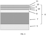
- the present invention relates to a coated cutting tool consisting of a substrate body and a coating, the coating comprises, in the order from the substrate body surface,
- the inner layer of (Ti,AI)N suitably has an average composition (Ti 1-v Al v )N, 0.45 ⁇ v ⁇ 0.67, preferably 0.55 ⁇ v ⁇ 0.65.
- the thickness of the inner layer of (Ti,AI)N is suitably from 1 to 5 ⁇ m, preferably from 2 to 4 ⁇ m.
- the inner layer of (Ti,AI)N can either be present as a (Ti,AI)N monolayer or as a (Ti,AI)N nano-multilayer of alternating (Ti,AI)N sub-layers.
- the inner layer of (Ti,AI)N is a first (Ti,AI)N nano-multilayer of alternating (Ti,AI)N sub-layers, wherein
- the first (Ti,AI)N nano-multilayer of alternating (Ti,AI)N sub-layers is suitably a nano-multilayer of one sub-layer (Ti 1-w Al w )N, 0.40 ⁇ w ⁇ 0.80, preferably 0.50 ⁇ w ⁇ 0.75, most preferably 0.60 ⁇ w ⁇ 0.70 and one sub-layer (Ti 1-a Al a )N, 0.20 ⁇ a ⁇ 0.65, preferably 0.35 ⁇ a ⁇ 0.60, most preferably 0.45 ⁇ a ⁇ 0.55, the Al content in the sub-layer (Ti 1-w Al w )N is higher than the Al content in the sub-layer (Ti 1-a Al a )N.
- the first (Ti,AI)N nano-multilayer comprises two or more (Ti,AI)N sub-layer stacks arranged immediately on top of each other, wherein within the same (Ti,AI)N sub-layer stack there exists at least two types of individual (Ti,AI)N sub-layers wherein the at least two types of individual (Ti,AI)N sub-layers have different Ti:Al atomic ratios, the overall Al content within each of the (Ti,AI)N sub-layer stacks increases from one (Ti,AI)N sub-layer stack to the next (Ti,AI)N sub-layer stack in the direction towards the outer surface of the coating.
- the increase in the overall Al content within each of the (Ti,AI)N sub-layer stacks from one (Ti,AI)N sub-layer stack to the next (Ti,AI)N sub-layer stack in the direction towards the outer surface of the coating of the first (Ti,AI)N nano-multilayer includes that the atomic ratio Ti:Al over several pairs of adjacent (Ti,AI)N sub-layers remains constant over several pairs of adjacent (Ti,AI)N sub-layers of one sub-layer stack and then the atomic ratio Ti:Al is lowered by a significant amount in the next several pairs of adjacent (Ti,AI)N sub-layers of a further sub-layer stack.
- the difference in the overall Al content between the (Ti,AI)N sub-layer stacks can be achieved in several ways, individually or in combination.
- an increase of the Al content can be achieved by the selection of the types and number of targets containing certain amounts of Al and Ti during the progress of the deposition process.
- the Al and Ti contents in the deposited coating layers can be varied by varying the deposition condition, such as bias and arc current.
- an outer (Ti,AI)N layer being a (Ti,AI)N nano-multilayer was deposited.
- the (Ti,AI)N nano-multilayers was deposited in the same manner as when depositing the sub-layer stack L2 of the previous (Ti,AI)N nano-multilayer for the sample, i.e., in the Hauzer HTC1000 equipment used a circular Arc-PVD technology (CARC+) using constant magnetic field configuration was applied during deposition.
- CARC+ circular Arc-PVD technology
- the cutting tool body was for the geometry SPHT120408 made out of a cemented carbide of the composition 90.6 wt% WC, 1.4 wt% (Ta, Nb)C and a binder phase of 8 wt% Co.
- the average WC grain size dWC was 0.8 ⁇ m.
- the target had a diameter of 100 mm.
- the reactive gas for the nitride deposition was N 2 .
- the deposition was carried out at an arc current at the target of about 150 A, a bias level of -40 V at a N 2 pressure of 10 Pa, and at a temperature of 550°C.
- the table rotation speed in the PVD reactor was set to 3 rpm.
- a comparative coated cutting tool essentially according to prior art US 8,709,583 with a top layer of metallic Al + gamma-Al 2 O 3 according to US 8,858,666 , was made by depositing a coating onto a cutting tool body being an insert having a geometry SX-3E300N02-CE4 (parting and grooving insert).
- the cutting tool body was made out of a cemented carbide of the composition 90.6 wt% WC, 1.4 wt% (Ta, Nb)C and a binder phase of 8 wt% Co.
- the average WC grain size dWC was 0.8 ⁇ m.
- This comparative cutting tool represents a cutting tool known to perform very well in a parting and grooving metal machining operation.
- the coating was made out of a 7-layer coating:
- the substrate was cleaned in alcohol and additionally cleaned by using an Ar ion bombardment prior to deposition of the layers in the vacuum chamber.
- Table 4 summarises the layer sequence.
- Layer # (from substrate) Layer Thickness] Layers 1 3 ⁇ m Ti 0.33 Al 0.67 N, single layer 2 0.6 ⁇ m gamma-Al 2 O 3 3 0.3 ⁇ m Ti 0.33 Al 0.67 N, single layer 4 0.1 ⁇ m gamma-Al 2 O 3 5 0.3 ⁇ m Ti 0.33 Al 0.67 N, single layer 6 0.1 ⁇ m gamma-Al 2 O 3 7 0.1 ⁇ m Al + gamma-Al 2 O 3
- a comparative coated cutting tool essentially according to prior art US 2023/0033516 A1 , was made by depositing a coating onto a cutting tool body being an insert having a geometry SPHT120408 (milling insert).
- the cutting tool body was made out of a cemented carbide of the composition 90.6 wt% WC, 1.4 wt% (Ta, Nb)C and a binder phase of 8 wt% Co.
- the average WC grain size dWC was 0.8 ⁇ m.
- Example 5 The layer structure provided in "Sample 5 (comparative)" is seen in table 5.
- Table 5 Layer # (from substrate)
- Layer Thickness Layer (Ti,Al)N sublayer composition 1 4 ⁇ m first (Ti,Al)N (nano-multilayer) Ti 0.33 Al 0.67 N/ Ti 0.50 Al 0.50 N (two different stacks L1 and L2) 2 0.6 ⁇ m gamma-Al 2 O 3 - 3 0.1 ⁇ m second (Ti,Al)N nano-multilayer Ti 0.33 Al 0.67 N/ Ti 0.50 Al 0.50 N (as L2) 4 0.1 ⁇ m gamma-Al 2 O 3 - 5 0.1 ⁇ m second (Ti,Al)N nano-multilayer Ti 0.33 Al 0.67 N/ Ti 0.50 Al 0.50 N (as L2) 6 0.1 ⁇ m gamma-Al 2 O 3 - 7 0.3 ⁇ m second (Ti,Al)N (nano-multilayer) Ti
- the hardness and plane strain modulus were determined for samples "Sample 1 (invention)", “Sample 2 (comparative)” and “Sample 3 (comparative)", according to the methods herein described. A first measurement was made at room temperature. A second measurement was made after 1 hour heat treatment at 800°C. Table 6 shows the results. Table 6. Sample Hardness [HV0.0015], room temp. Hardness [HV0.0015], 1 hour, 800°C Plane strain modulus [MPa], room temp. Plane strain modulus [MPa], 1 hour, 800°C Sample 1 (invention) 3068 2869 509 542 Sample 2 (comparative) 3414 2354 509 432 Sample 3 (comparative) 3586 3514 505 512
- nanolayered (Ti,AI)N/(Ti,Si)N coating gets much worse mechanical properties after heat treatment while the coating of the invention (Sample 1) substantially keeps its properties behaving similar to a monolayered heat stable (Ti,Si)N coating (Sample 3).
- the amount of wear at the cutting edge was determined.
Landscapes
- Chemical & Material Sciences (AREA)
- Chemical Kinetics & Catalysis (AREA)
- Engineering & Computer Science (AREA)
- Materials Engineering (AREA)
- Mechanical Engineering (AREA)
- Metallurgy (AREA)
- Organic Chemistry (AREA)
- Inorganic Chemistry (AREA)
- Cutting Tools, Boring Holders, And Turrets (AREA)
- Physical Vapour Deposition (AREA)
Priority Applications (3)
| Application Number | Priority Date | Filing Date | Title |
|---|---|---|---|
| EP23192670.0A EP4512928A1 (de) | 2023-08-22 | 2023-08-22 | Beschichtetes schneidwerkzeug |
| CN202480052767.0A CN121712926A (zh) | 2023-08-22 | 2024-08-19 | 涂覆型切削工具 |
| PCT/EP2024/073192 WO2025040615A1 (en) | 2023-08-22 | 2024-08-19 | A coated cutting tool |
Applications Claiming Priority (1)
| Application Number | Priority Date | Filing Date | Title |
|---|---|---|---|
| EP23192670.0A EP4512928A1 (de) | 2023-08-22 | 2023-08-22 | Beschichtetes schneidwerkzeug |
Publications (1)
| Publication Number | Publication Date |
|---|---|
| EP4512928A1 true EP4512928A1 (de) | 2025-02-26 |
Family
ID=87762422
Family Applications (1)
| Application Number | Title | Priority Date | Filing Date |
|---|---|---|---|
| EP23192670.0A Pending EP4512928A1 (de) | 2023-08-22 | 2023-08-22 | Beschichtetes schneidwerkzeug |
Country Status (3)
| Country | Link |
|---|---|
| EP (1) | EP4512928A1 (de) |
| CN (1) | CN121712926A (de) |
| WO (1) | WO2025040615A1 (de) |
Citations (7)
| Publication number | Priority date | Publication date | Assignee | Title |
|---|---|---|---|---|
| US7923130B2 (en) * | 2007-05-30 | 2011-04-12 | Sumitomo Electric Hardmetal Corp. | Surface-coated cutting tool |
| US20120114436A1 (en) * | 2009-06-01 | 2012-05-10 | Seco Tools Ab | Nanolaminated coated cutting tool |
| US8709583B2 (en) | 2009-03-23 | 2014-04-29 | Walter Ag | PVD coated tool |
| US20140147683A1 (en) * | 2011-06-30 | 2014-05-29 | Oerlikon Trading Ag, Trubbach | Nano-layer coating for high performance tools |
| US8858666B2 (en) | 2009-09-23 | 2014-10-14 | Walter Ag | Tool coating |
| US20230033516A1 (en) | 2019-12-19 | 2023-02-02 | Walter Ag | Coated cutting tool |
| WO2023041415A1 (en) * | 2021-09-17 | 2023-03-23 | Ab Sandvik Coromant | A coated cutting tool |
-
2023
- 2023-08-22 EP EP23192670.0A patent/EP4512928A1/de active Pending
-
2024
- 2024-08-19 WO PCT/EP2024/073192 patent/WO2025040615A1/en active Pending
- 2024-08-19 CN CN202480052767.0A patent/CN121712926A/zh active Pending
Patent Citations (7)
| Publication number | Priority date | Publication date | Assignee | Title |
|---|---|---|---|---|
| US7923130B2 (en) * | 2007-05-30 | 2011-04-12 | Sumitomo Electric Hardmetal Corp. | Surface-coated cutting tool |
| US8709583B2 (en) | 2009-03-23 | 2014-04-29 | Walter Ag | PVD coated tool |
| US20120114436A1 (en) * | 2009-06-01 | 2012-05-10 | Seco Tools Ab | Nanolaminated coated cutting tool |
| US8858666B2 (en) | 2009-09-23 | 2014-10-14 | Walter Ag | Tool coating |
| US20140147683A1 (en) * | 2011-06-30 | 2014-05-29 | Oerlikon Trading Ag, Trubbach | Nano-layer coating for high performance tools |
| US20230033516A1 (en) | 2019-12-19 | 2023-02-02 | Walter Ag | Coated cutting tool |
| WO2023041415A1 (en) * | 2021-09-17 | 2023-03-23 | Ab Sandvik Coromant | A coated cutting tool |
Non-Patent Citations (2)
| Title |
|---|
| M.E. FITZPATRICKA.T. FRYP. HOLDWAYF.A. KANDILJ. SHACKLETONL. SUOMINEN: "Determination of Residual Stresses by X-ray Diffraction", A MEASUREMENT GOOD PRACTICE GUIDE, no. 52, 2005 |
| ROEBUCK ET AL.: "Measurement Good Practice", November 1999, NATIONAL PHYSICAL LABORATORY, pages: 19 - 20 |
Also Published As
| Publication number | Publication date |
|---|---|
| WO2025040615A1 (en) | 2025-02-27 |
| CN121712926A (zh) | 2026-03-20 |
Similar Documents
| Publication | Publication Date | Title |
|---|---|---|
| EP3676422B1 (de) | Verschleissfeste beschichtung für pvd-werkzeuge mit tialn-nanoschichten-filmen | |
| KR101831014B1 (ko) | 코팅된 절삭 공구 인서트 | |
| JP6037255B1 (ja) | 表面被覆切削工具およびその製造方法 | |
| CN100484672C (zh) | 涂覆切削刀片 | |
| EP1736565A1 (de) | Verbundbeschichtung für Endbearbeitung von gehärtetem Stahl | |
| EP3311939B1 (de) | Oberflächenbeschichtetes schneidwerkzeug | |
| US12553137B2 (en) | Coated cutting tool | |
| JP5321975B2 (ja) | 表面被覆切削工具 | |
| KR20180135497A (ko) | 표면 피복 절삭 공구 및 그 제조 방법 | |
| US11104986B2 (en) | Metal cutting tool with multi-layer coating | |
| JP2010512251A (ja) | 被覆切削工具 | |
| JP2023506295A (ja) | 被覆切削工具 | |
| EP3757252B1 (de) | Beschichtetes schneidwerkzeug | |
| EP4512928A1 (de) | Beschichtetes schneidwerkzeug | |
| CN104508185B (zh) | 涂层切削刀片 | |
| US20250269435A1 (en) | Coated cutting tool | |
| WO2025132516A1 (en) | A coated cutting tool | |
| EP4624622A1 (de) | Schneidwerkzeug mit tialn-schicht | |
| WO2022239139A1 (ja) | 切削工具 |
Legal Events
| Date | Code | Title | Description |
|---|---|---|---|
| PUAI | Public reference made under article 153(3) epc to a published international application that has entered the european phase |
Free format text: ORIGINAL CODE: 0009012 |
|
| STAA | Information on the status of an ep patent application or granted ep patent |
Free format text: STATUS: THE APPLICATION HAS BEEN PUBLISHED |
|
| AK | Designated contracting states |
Kind code of ref document: A1 Designated state(s): AL AT BE BG CH CY CZ DE DK EE ES FI FR GB GR HR HU IE IS IT LI LT LU LV MC ME MK MT NL NO PL PT RO RS SE SI SK SM TR |
|
| STAA | Information on the status of an ep patent application or granted ep patent |
Free format text: STATUS: REQUEST FOR EXAMINATION WAS MADE |
|
| 17P | Request for examination filed |
Effective date: 20250826 |