EP4512756A1 - Verfahren und vorrichtung zum laden von falzpapierstapeln - Google Patents
Verfahren und vorrichtung zum laden von falzpapierstapeln Download PDFInfo
- Publication number
- EP4512756A1 EP4512756A1 EP24192096.6A EP24192096A EP4512756A1 EP 4512756 A1 EP4512756 A1 EP 4512756A1 EP 24192096 A EP24192096 A EP 24192096A EP 4512756 A1 EP4512756 A1 EP 4512756A1
- Authority
- EP
- European Patent Office
- Prior art keywords
- log
- folded sheets
- bucket
- path
- loading
- Prior art date
- Legal status (The legal status is an assumption and is not a legal conclusion. Google has not performed a legal analysis and makes no representation as to the accuracy of the status listed.)
- Pending
Links
Images


Classifications
-
- B—PERFORMING OPERATIONS; TRANSPORTING
- B65—CONVEYING; PACKING; STORING; HANDLING THIN OR FILAMENTARY MATERIAL
- B65H—HANDLING THIN OR FILAMENTARY MATERIAL, e.g. SHEETS, WEBS, CABLES
- B65H45/00—Folding thin material
- B65H45/12—Folding articles or webs with application of pressure to define or form crease lines
- B65H45/24—Interfolding sheets, e.g. cigarette or toilet papers
-
- B—PERFORMING OPERATIONS; TRANSPORTING
- B65—CONVEYING; PACKING; STORING; HANDLING THIN OR FILAMENTARY MATERIAL
- B65H—HANDLING THIN OR FILAMENTARY MATERIAL, e.g. SHEETS, WEBS, CABLES
- B65H31/00—Pile receivers
- B65H31/04—Pile receivers with movable end support arranged to recede as pile accumulates
- B65H31/08—Pile receivers with movable end support arranged to recede as pile accumulates the articles being piled one above another
- B65H31/10—Pile receivers with movable end support arranged to recede as pile accumulates the articles being piled one above another and applied at the top of the pile
-
- B—PERFORMING OPERATIONS; TRANSPORTING
- B65—CONVEYING; PACKING; STORING; HANDLING THIN OR FILAMENTARY MATERIAL
- B65H—HANDLING THIN OR FILAMENTARY MATERIAL, e.g. SHEETS, WEBS, CABLES
- B65H31/00—Pile receivers
- B65H31/30—Arrangements for removing completed piles
- B65H31/3027—Arrangements for removing completed piles by the nip between moving belts or rollers
-
- B—PERFORMING OPERATIONS; TRANSPORTING
- B65—CONVEYING; PACKING; STORING; HANDLING THIN OR FILAMENTARY MATERIAL
- B65H—HANDLING THIN OR FILAMENTARY MATERIAL, e.g. SHEETS, WEBS, CABLES
- B65H31/00—Pile receivers
- B65H31/30—Arrangements for removing completed piles
- B65H31/3054—Arrangements for removing completed piles by moving the surface supporting the lowermost article of the pile, e.g. by using belts or rollers
- B65H31/3063—Arrangements for removing completed piles by moving the surface supporting the lowermost article of the pile, e.g. by using belts or rollers by special supports like carriages, containers, trays, compartments, plates or bars, e.g. moved in a closed loop
-
- B—PERFORMING OPERATIONS; TRANSPORTING
- B65—CONVEYING; PACKING; STORING; HANDLING THIN OR FILAMENTARY MATERIAL
- B65H—HANDLING THIN OR FILAMENTARY MATERIAL, e.g. SHEETS, WEBS, CABLES
- B65H31/00—Pile receivers
- B65H31/30—Arrangements for removing completed piles
- B65H31/3081—Arrangements for removing completed piles by acting on edge of the pile for moving it along a surface, e.g. by pushing
-
- B—PERFORMING OPERATIONS; TRANSPORTING
- B65—CONVEYING; PACKING; STORING; HANDLING THIN OR FILAMENTARY MATERIAL
- B65H—HANDLING THIN OR FILAMENTARY MATERIAL, e.g. SHEETS, WEBS, CABLES
- B65H31/00—Pile receivers
- B65H31/32—Auxiliary devices for receiving articles during removal of a completed pile
-
- B—PERFORMING OPERATIONS; TRANSPORTING
- B65—CONVEYING; PACKING; STORING; HANDLING THIN OR FILAMENTARY MATERIAL
- B65H—HANDLING THIN OR FILAMENTARY MATERIAL, e.g. SHEETS, WEBS, CABLES
- B65H2301/00—Handling processes for sheets or webs
- B65H2301/40—Type of handling process
- B65H2301/42—Piling, depiling, handling piles
- B65H2301/422—Handling piles, sets or stacks of articles
- B65H2301/4223—Pressing piles
-
- B—PERFORMING OPERATIONS; TRANSPORTING
- B65—CONVEYING; PACKING; STORING; HANDLING THIN OR FILAMENTARY MATERIAL
- B65H—HANDLING THIN OR FILAMENTARY MATERIAL, e.g. SHEETS, WEBS, CABLES
- B65H2301/00—Handling processes for sheets or webs
- B65H2301/40—Type of handling process
- B65H2301/44—Moving, forwarding, guiding material
- B65H2301/447—Moving, forwarding, guiding material transferring material between transport devices
- B65H2301/4473—Belts, endless moving elements on which the material is in surface contact
-
- B—PERFORMING OPERATIONS; TRANSPORTING
- B65—CONVEYING; PACKING; STORING; HANDLING THIN OR FILAMENTARY MATERIAL
- B65H—HANDLING THIN OR FILAMENTARY MATERIAL, e.g. SHEETS, WEBS, CABLES
- B65H2301/00—Handling processes for sheets or webs
- B65H2301/40—Type of handling process
- B65H2301/44—Moving, forwarding, guiding material
- B65H2301/447—Moving, forwarding, guiding material transferring material between transport devices
- B65H2301/4476—Endless transport devices with compartments
-
- B—PERFORMING OPERATIONS; TRANSPORTING
- B65—CONVEYING; PACKING; STORING; HANDLING THIN OR FILAMENTARY MATERIAL
- B65H—HANDLING THIN OR FILAMENTARY MATERIAL, e.g. SHEETS, WEBS, CABLES
- B65H2301/00—Handling processes for sheets or webs
- B65H2301/40—Type of handling process
- B65H2301/44—Moving, forwarding, guiding material
- B65H2301/447—Moving, forwarding, guiding material transferring material between transport devices
- B65H2301/4478—Transport device acting on edge of material
-
- B—PERFORMING OPERATIONS; TRANSPORTING
- B65—CONVEYING; PACKING; STORING; HANDLING THIN OR FILAMENTARY MATERIAL
- B65H—HANDLING THIN OR FILAMENTARY MATERIAL, e.g. SHEETS, WEBS, CABLES
- B65H2405/00—Parts for holding the handled material
- B65H2405/10—Cassettes, holders, bins, decks, trays, supports or magazines for sheets stacked substantially horizontally
- B65H2405/15—Large capacity supports arrangements
-
- B—PERFORMING OPERATIONS; TRANSPORTING
- B65—CONVEYING; PACKING; STORING; HANDLING THIN OR FILAMENTARY MATERIAL
- B65H—HANDLING THIN OR FILAMENTARY MATERIAL, e.g. SHEETS, WEBS, CABLES
- B65H2405/00—Parts for holding the handled material
- B65H2405/30—Other features of supports for sheets
- B65H2405/35—Means for moving support
- B65H2405/352—Means for moving support in closed loop
- B65H2405/3521—Means for moving support in closed loop rail guided means, e.g. without permanent interconnection
-
- B—PERFORMING OPERATIONS; TRANSPORTING
- B65—CONVEYING; PACKING; STORING; HANDLING THIN OR FILAMENTARY MATERIAL
- B65H—HANDLING THIN OR FILAMENTARY MATERIAL, e.g. SHEETS, WEBS, CABLES
- B65H2405/00—Parts for holding the handled material
- B65H2405/30—Other features of supports for sheets
- B65H2405/36—Multiple support
-
- B—PERFORMING OPERATIONS; TRANSPORTING
- B65—CONVEYING; PACKING; STORING; HANDLING THIN OR FILAMENTARY MATERIAL
- B65H—HANDLING THIN OR FILAMENTARY MATERIAL, e.g. SHEETS, WEBS, CABLES
- B65H2701/00—Handled material; Storage means
- B65H2701/10—Handled articles or webs
- B65H2701/19—Specific article or web
- B65H2701/1924—Napkins or tissues, e.g. dressings, toweling, serviettes, kitchen paper and compresses
Definitions
- This invention generally relates to an accumulator for temporarily storing and accumulating logs of elongated product, such as logs of paper products such as paper towels or facial tissues. More specifically, although not exclusively, the invention relates to an accumulator for storing and accumulating logs of elongated rolls or stacks of sheet products such as paper, paper towels, facial tissues and the like.
- Accumulators are used in manufacturing systems, and particularly paper processing systems, to store elongated logs of product that have been formed into elongated stacks prior to being reduced in length for commercial packaging. For example, during formation of folded or interfolded paper towels, the paper towels are initially formed into an elongated stack of paper towels that can be in excess of one hundred inches long. This log is then passed to downstream processing systems to be sawed into shorter lengths, such as four (4) to eighteen (18) inch lengths. These shorter lengths are then packaged for consumer use.
- the accumulators store the logs as they are dispensed from the portion of the system that forms the logs (e.g. a folder or interfolder) in the event that there is a breakdown, scheduled maintenance, or other downtime experienced by the system.
- the accumulator allows other downstream systems that are not experiencing downtime to continue to operate. This can be very beneficial in the event that either system needs to run continuously to avoid long reset or startup time as well as portions of a system that can generate large amounts of waste until it is ramped up to standard operating speeds or conditions.
- the feed arrangement includes a pusher element that pushes the logs laterally into the buckets in a direction that is generally perpendicular to the direction of travel of the buckets.
- the bucket and the feed arrangement must be aligned during the process of loading a log into the bucket.
- logs of stacked paper products are typically void of any central core, such as in wound products like rolls of paper towels or toilet paper.
- the lack of a central core can reduce the rigidity of the log such that the log should be supported substantially along its entire length and not merely at the ends thereof.
- the buckets and the feed arrangement need to be maintained at a constant relative position during the loading operation to prevent damaging the logs or otherwise prevent interference between the components of the buckets and the feed arrangement.
- the accumulator typically includes a transport system that includes an continuous carrier arrangement that defines a continuous path, e.g. a pair of parallel chains, that transports the buckets vertically up and down repeatedly.
- the buckets change vertical direction, typically, as the chains rotate about sprockets.
- the buckets will tend to start to swing due to the acceleration/deceleration of buckets.
- the swinging buckets can cause damage to the accumulator or cause the product to be spilled from the buckets.
- the present invention provides improvements over the art that permits faster throughput through an accumulator while preventing or reducing increases in swinging magnitude of the buckets.
- New and improved accumulators for storing logs of folded sheets is provided. Methods of use such as loading and unloading of the accumulator are also provided.
- a method of loading an accumulator with logs of folded sheets formed by being separated from a continuously forming stream of sheets exiting a sheet folder is provided.
- the stream of folded sheet are formed along a stacking axis.
- the method includes moving a log holding bucket along a loading path.
- the log holding bucket has a log supporting surface.
- the method includes transporting a log of folded sheets separated from the stream of sheets away from the stream of sheets along the loading path.
- the method includes loading the log of folded sheets onto the log support surface while the log of folded sheets and the log holding bucket travel along the loading path.
- the step of transporting the log of folded sheets away from the stream of sheets includes transporting the log with a finger of a carriage.
- the step of loading the log of folded sheets onto the log support surface includes abutting a side of the log of folded sheets against an abutment adjacent the loading path by retracting the finger from the loading path.
- the abutment prevents the log of folded sheets from being retracted from the loading path with the finger thereby removing the log of folded sheets from the finger and transferring to the log of folded sheets to the supporting surface.
- the step of loading the log of folded sheets onto the log supporting surface includes:
- the method includes tipping the bucket after the step of loading the log of folded sheets onto the log support surface such that the log support surface is less orthogonal to the loading path than during the step of loading the log of folded sheets onto the log support surface.
- the loading path is coaxial with the stacking axis such that the sheets forming the log of folded sheets travel along a single axis while:
- the method includes (a) building the log of folded sheets on a build finger.
- the method includes separating the log of folded sheets from the stream of sheets with the log of folded sheets supported by the build finger.
- the step of transporting the log of folded sheets along the loading path includes transporting the log of folded sheets along the loading path using the build finger.
- the step of loading the log of folded sheets onto the log support surface includes directly transferring the log of folded sheets from the build finger to the log support surface while the bucket and build finger travel along the loading path.
- the step of loading the log of folded sheets onto the log support surface includes retracting the build finger from the loading path.
- the step of loading includes abutting a side of the log of folded sheets against an abutment adjacent the loading path as the build finger is being retracted from the loading path such that the log of folded sheets is prevented from being retracted from the loading path with the build finger thereby removing the log of folded sheets from the build finger and transferring to the log of folded sheets to the supporting surface.
- the method includes building the log of folded sheets on a build finger.
- the method includes separating the log folded sheets from the stream of sheets.
- the method includes, while the sheets forming the log of folded sheets are supported by the build finger, transferring the log of folded sheets to a transfer finger.
- the step of transporting the log of folded sheets along the loading path includes transporting the log of folded sheets along the loading path using the transfer finger.
- the step of loading the log of folded sheets onto the log support surface includes directly transferring the log of folded sheets from the transfer finger to the log support surface while the bucket and transfer finger travel along the loading path.
- the step of loading the log of folded sheets onto the log support surface includes retracting the transfer finger from the loading path.
- the step of loading includes abutting a side of the log of folded sheets against an abutment adjacent the loading path as the transfer finger is being retracted from the loading path such that the log of folded sheets is prevented from being retracted from the loading path with the transfer finger thereby removing the log of folded sheets from the build finger and transferring to the log of folded sheets to the supporting surface.
- the step of loading the log of folded sheets onto the log support surface does not include transporting the log of folded sheets along an axis transverse to the loading path.
- the method includes building the log of folded sheets along the stacking axis, the stacking axis being a vertical axis that is coaxial with the loading axis.
- the method includes separating the log of folded sheets from the stream of sheets. The buckets and log of folded sheets move vertically downward while traveling along the loading path.
- the method includes tipping the bucket after the step of loading the log of folded sheets onto the log support surface such that the log support surface is less orthogonal to the loading path than during the step of loading the log of folded sheets onto the log support surface.
- the log of folded sheets is vertically supported on at least two sides of the log of folded sheets.
- the step of loading the log of folded sheets onto the log supporting surface includes transporting, in a first direction, the log of folded sheets along the loading path with the log of folded sheets supported by a finger of a carriage.
- the step of loading includes moving the log holding bucket along the loading path in a second direction such that the finger of the carriage passes the log supporting surface along the loading path and the log is transferred to the log supporting surface.
- an apparatus including an accumulator, a log transport mechanism, and means for transferring the log of folded sheets from the transport mechanism to a bucket.
- the accumulator is configured for holding a plurality of logs of folded sheets.
- the accumulator includes a plurality of buckets carried along a continuous path. A portion of the continuous path includes a loading path. Preferably, but not required, the buckets of the accumulator travel at a constant speed along the continuous path.
- the log transport mechanism is configured to carry a log of folded sheets along the loading path.
- the means for transferring the log of folded sheets transfers the log from the log transport mechanism to one of the buckets of the plurality of buckets while the log of folded sheets and the bucket travel along the loading path.
- the means for transferring the log of folded sheets from the log transport mechanism to one of the buckets of the plurality of buckets while the log of folded sheets and the bucket travel along the loading path includes a finger of the log transport mechanism that travels along the loading path at a speed greater than the bucket travels along the loading path such that the finger passes the bucket while traveling along the loading path and the log of folded sheets is transferred to the bucket.
- the means is provided by a transport mechanism that transports the log along the loading path in a direction opposite the bucket travels.
- the bucket includes a plurality of spaced apart bucket portions forming gaps therebetween and the finger includes a plurality of finger portions forming gaps therebetween.
- the finger portions pass through the gaps formed between adjacent bucket portions as the finger passes the bucket such that the bucket portions abut a side of the log of folded sheets that is being supported by the finger portions thereby transferring the log of folded sheets to the bucket portions.
- the log of folded sheets is separated from a stream of sheets forming along a stacking axis, the stacking axis being coaxial with the loading path.
- the stacking axis and loading path are coaxial such that the sheets forming the log of folded sheets travel along a single axis 1) while in the stream of sheets; 2) are carried by the log transport mechanism; and 3) are transferred from the log transport mechanism to the bucket.
- the buckets travel along the loading path with a log support surface upon which the logs are supported when the logs are transferred to the buckets being substantially orthogonal to the loading path.
- the buckets tip after receiving a log of folded sheets such that the log support surface is less orthogonal to the loading path after receiving the log of folded sheets and the log of folded sheets is supported on at least two sides.
- tipping can occur using a cam follower and guide arrangement.
- tipping could be produced by an actuator such as a motor.
- a log unloading arrangement including a plurality of laterally spaced indexing belts forming gaps therebetween.
- a portion of the continuous path of the accumulator includes an unloading path.
- Each bucket travels along the unloading path and unloads the log of folded sheets carried thereby onto the indexing belts.
- the laterally spaced belts extend into the unloading path.
- Each bucket passes through the gaps formed between the laterally spaced indexing belts to transfer the log of folded sheets to the indexing belts.
- the log of folded sheets carried by the bucket has a length, a width and a height that are perpendicular to one another.
- the length is the greatest dimension and is at least three times the width dimension.
- the height is aligned with the unloading path as the bucket travels along the unloading path.
- the indexing belts are aligned with the width such that the indexing belts need index a log of folded sheets less than the length of the log of folded sheets to permit a subsequent bucket and subsequent log carried by the subsequent bucket to clear the log of folded sheets.
- the means for transferring the log of folded sheets from the log transport mechanism to one of the buckets of the plurality of buckets while the log of folded sheets and the bucket travel along the loading path includes a transport mechanism that carries the log along the loading path at an opposite direction as the bucket travels along the loading path.
- a log unloading arrangement including a slide table having a plurality of laterally spaced bucket unloading portions forming gaps therebetween.
- a portion of the continuous path of the accumulator includes an unloading path.
- Each bucket travels along the unloading path and unloads the log of folded sheets carried thereby onto the bucket unloading portions of the slide table.
- the laterally spaced bucket unloading portions extend into the unloading path.
- Each bucket passes through the gaps formed between the laterally spaced bucket unloading portions to transfer the log of folded sheets to the slide table.
- the apparatus includes at least one pusher paddle configured to transport an unloaded log supported by the bucket unloading portions of the slide table along the slide table and out of the unloading path.
- the unloaded log has a length, a width and a height that are perpendicular to one another.
- the length is the greatest dimension and is at least three times the width dimension.
- the height is aligned with the unloading path as the bucket travels along the unloading path.
- the at least one pusher paddle transports the unloaded log along an axis that is aligned with the width such that the unloaded log is transported entirely out of the unloading path.
- the at least one pusher paddle has a paddle member and a support leg.
- the paddle member is located vertically above the slide table and abuts a vertical side of the unloaded log when the at least one pusher paddle transports the unloaded log out of the unloading path.
- the support leg supports the paddle member and extends vertically through a slot formed in the slide table.
- the slot through which the support leg extends is formed, at least in part, in the bucket unloading portion and is not provided by a gap through which the bucket passes as the log is transferred from the bucket to the bucket unloading portions of the slide table.
- a longitudinal conveyor having first and second conveyor belts having adjustable spacing therebetween.
- the longitudinal conveyor is configured to transport the unloaded log parallel to the length of the unloaded log.
- the at least one pusher paddle transports the unloaded log from the slide table into the longitudinal conveyor and between the first and second conveyor belts.
- an accumulator unloading apparatus for unloading a log of folded sheets from a bucket of an accumulator traveling along an unloading path.
- the log has a length, a width and a height.
- the apparatus includes an indexing conveyor including laterally spaced apart indexing belts.
- the indexing conveyor has a log receiving region that intersects the unloading path.
- the indexing belts pass through the log receiving region.
- the indexing conveyor has gaps formed between adjacent indexing belts configured to pass portions of the bucket therethrough as the bucket travels along the unloading path.
- the apparatus includes a longitudinal conveyor including a first conveyor belt and a second conveyor belt spaced apart from the first conveyor belt.
- the first and second conveyor belts are moveable relative to one another to adjust a spacing therebetween including a first spacing that is greater than the height of the log and a second spacing that is equal to or less than the height of the log.
- the first conveyor belt is guided along an undulating path.
- the undulating path has a plurality of peaks and a plurality of valleys. A first peak of the plurality of peaks is positioned laterally between a corresponding pair of indexing belts of the indexing conveyor and a first valley of the plurality of valleys is aligned with a first indexing belt of the plurality of indexing belts of the indexing conveyor.
- the first conveyor belt is positionable relative to the plurality of indexing belts between a first orientation in which the second conveyor belt is closer to the indexing belts than the first conveyor belt and a second orientation in which the second conveyor belt is closer to the first conveyor belt than the indexing belts.
- the first indexing belt when in the second orientation, is received in the first valley of the undulating path to a greater extent than when in the first orientation.
- At least a portion of the undulating path defining the first valley extends through a perimeter defined by a path traveled by the first indexing belt.
- the first and second conveyor belts are spaced from the unloading path along indexing belts a distance of at least 2 times the width of the log.
- the first conveyor belt is configured to move perpendicular to the indexing belts to lift the log relative to the indexing belts when the log is located in the space formed between the first and second belts.
- the first conveyor belt is configured to move relative to the indexing belts parallel to the unloading path to lift the log relative to the indexing belts when the log is located in the space formed between the first and second belts.
- the lifting of the log relative to the indexing belts entirely disengages the log from the indexing belts.
- the indexing belts transport the log in a direction that is perpendicular to a length of the log and the first and second conveyor belts transport the log in a direction that is parallel to the length of the log.
- a guide table providing guide surfaces interposed between the indexing belts for supporting portions of the log that are offset from the indexing belts.
- the guide surfaces are offset from the log receiving region and the gaps.
- a method of unloading an accumulator includes passing a bucket of an accumulator carrying a log of folded sheets along an unloading path of the accumulator through the log receiving region of the accumulator unloading apparatus of a prior unloading apparatus.
- the method includes transferring the log of folded sheets from the bucket to the indexing belts as the bucket passes through the log receiving region.
- a portion of the bucket passes through one of the gaps in the log receiving region formed between adjacent indexing belts while traveling along the unloading path and as the log is transferred to the indexing belts.
- the method includes transporting the log with the indexing belts parallel to the width of the log into the longitudinal conveyor and between the first and second conveyor belts.
- the method includes transporting the log with the first and second conveyor belts parallel to the length of the log with the first and second conveyor belts in the second spacing, with the first and second conveyor belts engaging the log, and with the first conveyor belt in the second orientation.
- an accumulator unloading apparatus for unloading a log of folded sheets from a bucket of an accumulator traveling along an unloading path.
- the log has a length, a width and a height with the length being greater than the width and the height.
- the apparatus includes a slide table, a longitudinal conveyor, and at least one pusher paddle.
- the slide table has a log support surface.
- the slide table includes laterally spaced apart bucket unloading portions forming a log receiving region that intersects the unloading path.
- the slide table has gaps formed between adj acent bucket unloading portions configured to permit portions of the bucket supporting the log to pass through the log receiving region as the bucket travels along the unloading path.
- the longitudinal conveyor includes a first conveyor belt and a second conveyor belt spaced apart from the first conveyor belt.
- the first and second conveyor belts are moveable relative to one another to adjust a spacing therebetween including a first spacing that is greater than the height of the log and a second spacing that is equal to or less than the height of the log.
- the longitudinal conveyor is configured to transport the log parallel to the length of the log.
- the at least one pusher paddle is actuatable parallel to a pusher paddle axis that is parallel to the width of the log to transport the log from the log receiving region into the longitudinal conveyor between the first and second conveyor belts.
- the at least one pusher paddle transports the log by pushing the log along the support surface of the slide table.
- a carriage and an actuator are provided.
- the carriage is movable, by the actuator, generally parallel to the pusher paddle axis.
- the at least one pusher paddle includes a plurality of pusher paddles. Each pusher paddle is attached to the carriage for movement with the carriage parallel to the pusher paddle axis.
- Each pusher paddle includes:
- the at least one pusher paddle extends vertically through a slot formed in the slide table such that a portion of the pusher paddle is vertically above the support surface of the slide table and a portion is vertically below the support surface of the slide table.
- the portion of the pusher paddle that is vertically above the support surface has a width being perpendicular to the pusher paddle axis and perpendicular to the unloading path that is greater than a width of the slot.
- the slot formed in the slide table is formed in one of the bucket unloading portions and extends longitudinally parallel to the pusher paddle axis.
- the at least one pusher paddle has a paddle member and a support arm.
- the support arm has a bent neck such that the paddle member may be located between the first and second conveyor belts while the support arm is positioned offset from the belts of the longitudinal conveyor when the pusher paddle transports the unloaded log into the longitudinal conveyor.
- the method includes passing a portion of the bucket through one of the gaps in the log receiving region formed between adjacent bucket unloading portions while the bucket travels along the unloading path and as the log is transferred to the slide table.
- the method includes transporting the log with the at least one pusher paddle parallel to the width of the log into the longitudinal conveyor and between the first and second conveyor belts.
- the method includes transporting the log with the first and second conveyor belts parallel to the length of the log with the first and second conveyor belts in the second spacing.
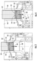
- FIG. 1 is a simplified schematic illustration of a system 100 for forming logs of folded sheets of material such as paper towels or facial tissues.
- the system 100 includes a folding arrangement 102 that includes a pair of folding rolls 106 downstream from one or more knife rolls 104.
- the knife rolls 104 sever sheets of material from a continuous web of material.
- the sheets are fed to the folding rolls 106 where the sheets are folded.
- the sheets may be interfolded or non-interfolded, but it is contemplated that the present application would have more applicability to interfolded sheets.
- a continuously building stream of folded sheets will exit the folding rolls 106. Typically, this will be vertically below the folding rolls 106 however horizontally oriented systems are contemplated.
- the system 100 includes a separator 110 downstream of the folding rolls 106 for separating individual logs of folded sheets (e.g. a stack of an approximate predetermined number of sheets) from the stream of folded sheets.
- the separator 110 can include a plurality of different fingers and not all separators will have the same number or types of fingers.
- build fingers can support a bottom of a log of folded sheets as the sheets are stacking on the build fingers until the predetermined number of sheets has been built onto the build fingers.
- Count fingers can be inserted into the stream to make a break between the top of the log and the bottom of the next log to be built.
- Transfer fingers can be used for transferring built logs from the stream to other components. In some examples, some fingers could perform multiple functions. For example, some fingers could be both a build finger and a transfer finger.
- the fingers are carried by carriages for moving the fingers parallel to the axis 112 the stream of sheets is formed illustrated by arrow 114 as well as laterally relative to the axis 112 into and out of the stream of sheets illustrated by arrow 116.
- the separator 110 includes opposed upper count fingers 120, opposed lower count fingers 122, opposed upper separator fingers 124, opposed lower separator fingers 126, and a transfer finger 128.
- each finger is independently carried by a corresponding carriage for the required motion represented by arrows 114, 116.
- the system 100 includes an accumulator 130 illustrated in part in FIG. 1 that has a plurality of log holding buckets 132 (referred to generally as buckets) that carry the formed logs away from the folding arrangement.
- the accumulator 130 can hold a predetermined number of logs.
- the buckets 132 along a continuous path to be cyclically loaded with a log and then unloaded at a different location.
- the buckets 132 may be carried along the continuous path by belt 134 or driven along the path using other means such as actuators.
- the buckets 132 generally include a log support 136 that is carried by bucket frame 138.
- the log support 136 is L-shaped.
- the log support 136 is formed from a plurality of bucket portions 139 that are laterally spaced apart forming gaps 141 therebetween.
- the bucket portions 139 are attached to bucket frame 138 such that they travel together about the continuous path of the accumulator 130.
- the L-shaped log support 136 has first and second log support surfaces defined by surfaces 142, 144 of the bucket portions 139.
- a loading path forms a portion of the continuous path along which the buckets 132 travel.
- the buckets 132 can be loaded with a corresponding log.
- the loading path is generally vertically oriented and is aligned with sheet building axis 112.
- the loading path is directly vertically below where the continuous stream of sheets is built and below the folding arrangement.
- logs that are separated from the stream of sheets can be directly transferred into a corresponding bucket within the loading path while traveling along a single axis.
- axes 112, 146 are parallel and coaxial.
- the finger supporting log 105 could move in a non-parallel manner rather than having the log and bucket 132 moved parallel to one another and then using an actuator to push the log 105 laterally off of the associated finger.
- first log support surfaces 142 of the bucket portions 139 are substantially orthogonal to the axis 146 and the second log support surfaces 144 are substantially parallel when traveling along the loading path.
- the buckets 132 may be tipped, as illustrated to an orientation where the first log support surfaces 142 are less orthogonal to axis 146 and second log support surfaces 144 are less parallel to axis 146 than when the buckets are traveling along the loading path.
- the buckets include cam followers 150 that cooperate with guides 152 to maintain the buckets 132 with first log support surface 142 orthogonal to axis 146 and second log support surfaces 144 parallel to axis 146.
- the accumulator 130 is configured to improve loading of the logs into the buckets and to reduce any need to stop and start the accumulator 130 (e.g. movement of the buckets 132 along the continuous path). It is also configured to prevent the need to laterally move the logs relative to their travel path, e.g. transverse to axis 112, while loading the logs into the buckets 132. This prevents rapid acceleration and deceleration of the logs which can result in skewing the shape of the logs, causing sheets to unfold due to air flow, or damage to the sheets within the logs.
- a log 105 has been separated from the continuously building stream of sheets 107.
- lower count fingers 122 and upper separator fingers 124 are above log 105 but below continuously building stream of sheets 107.
- Lower separator fingers 126 are below the log 105 such that the log 105 is positioned between lower count fingers 122 and lower separator fingers 126. All identified fingers are generally inserted into the path way represented by axis 112.
- the fingers 122, 124, 126 and log 105 are moving along axis 112 as illustrated by arrow 160.
- Transfer finger 128 is spaced away from the lower separator fingers 126 but located within the path of the sheets.
- the log 105 and lower separator fingers 126 have reached transfer finger 128.
- the lower separator fingers 126, log 105 and transfer finger 128 are traveling along axis 112 as illustrated by arrow 160 at substantially a same speed.
- the transfer finger 128 has carried the log 105 to the accumulator and to loading path thereof.
- the log 105 is separated from the stream of sheets and is being transported away from the stream of sheets along the loading path.
- the bucket 132 has been tipped such that the log support surface 142 is generally orthogonal to the loading path (e.g. axis 146).
- the bucket 132 and transfer finger 128 are both moving in the same direction along the loading path as illustrated by arrow 160.
- the transfer finger 128 and log 105 are not at a same location along the loading path and are axially spaced apart.
- the transfer finger 128 has caught up to bucket 132 such that finger 128 and surface 142 of bucket 132 are at a same axial location along the loading path and are traveling in a same direction and at a same speed along the loading path as illustrated by arrow 160.
- transfer finger 128 is laterally retracted from the loading path as illustrated by arrow 172.
- the log 105 is transferred to the bucket 132.
- Guide 174 acts as an abutment that abuts a side of the log 105 and prevents the log 105 from being retracted from the loading path with transfer finger 128.
- the log 105 is transferred to the bucket 132 while the bucket 132, log 105 and transfer finger are all traveling in the same direction along the loading path.
- first log support surface 142 is less orthogonal to axis 146 and second log support surface 144 is less parallel to axis 146.
- second log support surface 144 is now also supported by second log support surface 144.
- axes 112 and 146 in this example, are vertically oriented. Both the first and second log support surfaces 142, 144 vertically support log 105.
- transfer finger 128 transitions back toward the separator to receive and then transfer another log. This motion is illustrated by arrow 178.
- FIGS. 8 and 9 illustrate transferring the log 105 from finger 128 to bucket 132 using guide 174.
- finger 128 may be configured to travel a different faster speed than bucket 132 along the loading path such that the log 105 is transferred to the bucket 132 as finger 128 axially passes bucket 132 and particularly first log support surface 142.
- the transfer finger 128 and bucket 132 could move in opposite directions. For example, if bucket 132 were moving in a direction opposite arrow 160, e.g. vertically upward, a transfer could occur. Notably, opposite directions could be used in the situation where the build finger is used to directly transfer the log to the buckets 132.
- finger 128 need not be configured to support log 105 as well as to pass through log support 136 (e.g. the portions that define surfaces 142). Instead, the finger 128 need only be moved substantially adjacent (e.g. slightly vertically above) log support surface 142 immediately prior to retraction (arrow 172) and transfer of log 105 to bucket 132.
- the object e.g. finger 128, supporting the log as it is transferred from the stream of sheets to the bucket is not positioned laterally next to the bucket 132 such that the log 105 need be accelerated laterally, e.g. perpendicular to axis 146 to transfer from the supporting object to the bucket 132.
- axis 146 of the loading path is coaxial with the stacking axis 112 along which the folded sheets form the continuous stream of sheets.
- the sheets forming the log 105 that are loaded into bucket 132 travel along a single axis while the sheets are 1) in the stream of sheets, 2) being separated from the stream of sheets to form log 105, 3) being transported away from the stream of sheets while being part of the log 105, and 4) being loaded onto the log support surface 142.
- This provides for a compact arrangement while the transportation and movement of the log from the folding arrangement 102 to the accumulator 130 does not negatively impact the condition of log 105.
- FIGS. 1-10 illustrate the use of a transfer finger 128 to transfer the log 105 from the separator 110 to the accumulator 130
- other examples contemplate directly transporting the log 105 to the accumulator 130 and to the bucket 132 thereof using the fingers of the separator 110 upon which the log is built.
- Such an arrangement could use either the guide 174 and retraction mode or differential speed mode to transfer the log 105 to the bucket 132 from the corresponding finger.
- the length L2 of the log 105 is aligned with the width W1 of the bucket 132.
- the width W2 of the log 105 is aligned with the depth D1 of the bucket 132.
- the height H1 of the log 105 is aligned with a height H2 of the bucket 132 (these dimensions are generally illustrated in FIG. 5 and FIG. 2 ).
- the length L2 of the log 105 corresponds to the width W1 of the bucket and is at least 3 times greater than either the width W2 or height H1 of the log 105. Length is often 6-25 times greater than the width W2 or height H1.
- FIG. 11 a log unloading arrangement 200 for unloading log 105 from bucket 132 is illustrated.
- Log unloading arrangement 200 is also illustrated in FIG. 1 .
- FIG. 18 is an enlarged portion of the accumulator 130 and the log unloading arrangement 200.
- the log 105 will be transported to log saw where the log is chopped into shorter lengths.
- a portion of the continuous path of the accumulator 130 along which bucket 132 travels is an unloading path.
- the bucket 132 travels along the unloading path as illustrated by arrow 202.
- the log 105 is removed from bucket 132.
- the bucket 132 pivots to present the log support surface 142 generally orthogonal to the axis defined by the unloading path and arrow 202. This can be done in a similar fashion using cam follower 150 and guide 211.
- the log unloading arrangement 200 includes a plurality of indexing belts 210 that are laterally spaced a part. A portion 212 of each of the indexing belts 210 intersects with the unloading path of the accumulator 130. Adjacent pairs of indexing belts 210 have gaps 214 located there between. The gaps 214 are located proximate the portions 212 that intersect the unloading path of the accumulator 130.
- the gaps 214 are sized and configured to allow the bucket portions 139 to pass therethrough when traveling along the unloading path as illustrated by arrow 202.
- This configuration allows the log 105 to be transferred to the indexing belts 210. More particularly, the exposed bottom side of log 105 will abut engagement surfaces of the indexing belts 210 proximate the unloading portions 212 of the indexing belts 210.
- the log 105 will be lifted off of the log support surfaces 142 and onto belts 210. This also illustrated in FIG. 15 .
- the log 105 will be controlled by the indexing belts 210 and indexed away from the unloading portions 212 and unloading path of the accumulator 130 towards a longitudinal conveyor 220, as illustrated by arrow 218.
- the log 105 will move with indexing belts 210 perpendicular to the length L2 of the log 105 and typically parallel to the width W2 of the log 105.
- the log has to travel less distance to clear the unloading portions 212 to allow for a subsequent bucket 132 to unload its log onto indexing belts 210. This reduces the acceleration that is needed to be applied to the log 105 to have the log clear the unloading portions 212.
- the indexing belts 210 travel across a guide table 219 (see FIGS. 11 and 12 ) that has support surfaces 221 located laterally offset from the indexing belts 210.
- the guide table 219 and support surfaces 221 thereof support the portions of the log 105 that are not directly supported by indexing belts 210 as the log 105 is transferred to the longitudinal conveyor 220.
- the log 105 will typically pass through a log saw, not shown, when traveling parallel to length L2.
- the indexing belts 210 carry the log 105 into the longitudinal conveyor 220 which will convey the log 105 parallel to length L2.
- the longitudinal conveyor 220 includes a lower conveyor belt 222 and an upper conveyor belt 224.
- the lower and upper conveyor belts 222, 224 are spaced apart from one another an adjustable spacing S.
- the lower and upper conveyor belts 222, 224 are moveable relative to one another such that spacing S can be adjusted between a first spacing that is greater than the height H1 of log 105 (e.g. in an uncompressed state) that allows the log 105 to be indexed into the longitudinal conveyor 220 and a second spacing that is equal to or less than height H1 so that opposed sides (e.g. top and bottom sides) of the log 105 can be engaged by the lower and upper conveyor belts 222, 224 to transport the log 105 in the lengthwise direction (e.g. toward and/or through a log saw).
- the spacing S is reduced to less than height H1 such that the log 105 is compressed between lower and upper conveyor belts 222, 224.
- the log 105 can be exposed to significantly larger accelerations without deforming the shape or sheets of log 105.
- These larger accelerations allow for the log to travel a greater distance in the necessary amount of time required for the log 105 to clear the longitudinal conveyor 220 in time for the longitudinal conveyor to receive a subsequent log therein. This allows for acceleration parallel to the length L2 of the log with out the problems of unfolding of the sheets or deformation in the shape of the log.
- the lower conveyor belt 222 travels along an undulating path that defines a plurality of peaks 230 and valleys 232 between adjacent peaks 230.
- the portions of the travel path of the lower conveyor belt 222 that form the valleys 232 pass through the periphery defined by aligned indexing belts 210.
- an indexing belt 210 is aligned with each valley 232 of the undulating path of lower conveyor belt 222. Peaks 230 of the undulating path are positioned laterally offset from the indexing belts 210.
- the lower conveyor belt 222 is moveable relative to the indexing belts 210 such that the peaks 230 of the undulating path can be positioned on either side of the of the log engaging surface 240 of the indexing belts 210.
- the upper conveyor belt 224 is closer to the log engaging surface 240 of the indexing belts 210 than to the log engaging surface 242 of the lower conveyor belt 222. Further, the log engaging surface 242 of the lower conveyor belt 222 is offset below the log engaging surface 240. This allows the indexing belts 210 to index the log 105 between the lower and upper conveyor belts 222, 224.
- This configuration is illustrated in FIG. 13 . In particular, the portion of the log engaging surface 242 of the lower conveyor belt 222 passing through peaks 230 is positioned above the log engaging surface 240 of the indexing belts 210.
- the upper conveyor belt 224 is closer to the log engaging surface 242 of the lower conveyor belt 222 than to the log engaging surface 240 of the indexing belts 210. Further, the log engaging surface 242 of the lower conveyor belt 222 is offset above the log engaging surface 242. This allows the lower conveyor belt 222 to engage the log 105 on a side opposite that which is engaged by upper conveyor belt 224 such that the longitudinal conveyor 220 can longitudinally transport the log 105.
- the indexing belts 210 When the lower conveyor belt 222 is in the second position, the indexing belts 210 are received in their adjacent valley 232 defined by the undulating path of lower conveyor belt 222 to a greater extent than when the lower conveyor belt 222 is in the first position. In the first position, the indexing belts 210 may be entirely removed from the valleys 232.
- lower conveyor belt 222 will be actuated upwards, illustrated by arrow 250 when transitioning from the first position to the second position. During this motion, the log 105 will be lifted off of or have less weight thereof supported by the indexing belts 210. In a preferred embodiment, the upper conveyor belt 224 will be lowered towards the lower conveyor belt 222 as illustrated by arrow 252.
- the lower conveyor belt 222 will be lowered, illustrated by arrow 261 in FIG. 16 to permit a subsequent log to be indexed into the longitudinal conveyor 220 between the lower and upper conveyor belts 222, 224.
- the embodiments described herein allow for the accumulator 130 to operate such that the buckets 132 remain moving at a constant speed provided by the continuous path of the accumulator even through the unloading and loading paths during the unloading and loading processes. However, these embodiments reduce the complexity of the accumulator 130.
- Log unloading arrangement 300 could be put in place of log unloading arrangement 200 in FIGS. 1 and 18 and operates for the same purpose of unloading logs 105 from the buckets 132 of the accumulator 130.
- a portion of the continuous path of the accumulator 130 along which bucket 132 travels is an unloading path.
- the bucket 132 travels along the unloading path as illustrated by arrow 302. In this region of the path, the log 105 is removed from bucket 132.
- the bucket 132 pivots (illustrated by arrow 303) to present the log support surface 142 generally orthogonal to the axis defined by the unloading path and arrow 302. This can be done in a similar fashion using cam follower 150 and guide 311.
- the log unloading arrangement 300 includes a slide table 310 that includes bucket unloading portions 312 that are laterally spaced a part. Bucket unloading portions 312 of slide table 310 intersect with the unloading path of the accumulator 130. Adjacent pairs of bucket unloading portions 312 have gaps 314 located therebetween.
- the bucket unloading portions 312 form a bucket unloading region of the slide table 310.
- the gaps 314 are sized and configured to allow the bucket portions 139 to pass therethrough when traveling along the unloading path as illustrated by arrow 302. This configuration allows the log 105 to be transferred to the slide table 310. More particularly, the exposed bottom side of log 105 will abut engagement surfaces of the slide table 310 provided by the bucket unloading portions 312.
- the log 105, pusher paddles 313 will index the log 105 away from the bucket unloading portions 312 and unloading path of the accumulator 130 towards a longitudinal conveyor 320, as illustrated by arrow 318.
- the pusher paddles 313 will engage the log 105 by pushing on a side of the log 105.
- the pusher paddles 313 will engage a vertical side of the log 105 while a bottom side of the log 105 is supported by the support surface of the slide table 310.
- the log 105 will move with pusher paddles 313 by sliding on the support surface of slide table 310 perpendicular to the length L2 of the log 105 and typically parallel to the width W2 of the log 105 along a pusher paddle axis generally parallel to arrow 318.
- the log is required to travel a shorter distance to clear the bucket unloading portions 312 to allow for a subsequent bucket 132 to pass through gaps 314 and unload its log onto slide table 310. This reduces the acceleration that is needed to be applied to the log 105 to have the log 105 clear the bucket unloading portions 312 and the travel path of the subsequent bucket 132.
- each bucket unloading portion 312 includes a pusher slot 315.
- a support arm 317 of a corresponding pusher paddle 313 extends through the pusher slot 315 with a paddle member 319 of the pusher paddle 313 located vertically above the slide table 310.
- the pusher paddle 315 will travel through pusher slot 315 to index the log 105 towards the conveyor 320.
- the support arm 317 and paddle member 319 may be a single one piece component or separate components attached to one another.
- the paddle member 319 has a width that is greater than the width of the pusher slots 315.
- the width is preferably narrower than the space between adjacent bucket portions 139 of bucket 132. This allows the paddle member 319 to pass between adjacent bucket portions 139 in the direction illustrated by arrow 318.
- the support arm 317 With the paddle member 319 having a width greater than the width of the slots 315, the support arm 317 consequently has a width that is narrower than the width of the paddle members 319.
- other configurations are contemplated.
- paddle members 319 could be wider than the space between the portions of the bucket portions 139 that provides support surface 142.
- the paddle members 319 may have a width that is less than a space between the portion of buckets 132 that provide support surfaces 144 (e.g. the vertically upright portion of the bucket portion 139).
- support surface 144 has a different, smaller width than support surface 142 such that the gap between adjacent support surfaces 144 is greater than the gap between support surfaces 142, this could allow the paddle member 319 to have a larger width than the space between support surfaces 142 while still allowing the paddle member to clear the bucket 132 while indexing a log 105 away from the bucket unloading portions 312 of slide table 310.
- pusher paddles 313 are provided. However, more or less pusher paddles 313 could be provided.
- slots 315 are not required if the support arm 317 has a horizontal component parallel to arrow 318 that is substantially equal to or greater than the length of slots 315. Such an implementation could occur when the slide table 310 needs more surface area for supporting the log 105.
- the support arm 317 may simply pass through gaps 314 formed between portions 312. Thus gaps 314 could function as slots 315.
- the pusher paddles 313 are operably attached to a same carriage 325.
- the carriage 325 is mounted to linear slides 327 for linear motion illustrated by arrow 329.
- motion illustrated by arrow 329 corresponds to motion illustrated by arrow 318.
- An actuator 331 is attached to carriage 325 by linkage 333 to drive the carriage 325 along linear slides 327. To reduce time, the actuator 331 oscillates back and forth rather than rotates in a continuous circle.
- the paddle members 319 are located vertically above the slide table 310.
- Conveyor 320 is substantially similar to conveyor 220 and includes lower conveyor belt 322 and upper conveyor belt 324. However, the lower conveyor belt 322 need not have the undulating configuration as described above for conveyor 220. This configuration provides for a simpler implementation of conveyor 320.
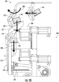
- FIG. 25 illustrates the pusher paddles 313 having pushed log 105 into conveyor 320.
- the support arm 317 has a bent neck region 337 that allows the paddle member 319 to be pushed into the space formed between the lower and upper conveyor belts 322, 324.
- a log stop 335 limits pushing the log 105 to far into or through the conveyor 105 in the direction 318.
- the actuator 331 will return pusher paddles 313 back to its starting point, such as illustrated in FIG. 21 as illustrated by arrow 339.
- the pusher paddles 313 will be in position for pushing the next log 105.
- the lower and upper conveyor belts 322, 324 are spaced apart from one another an adjustable spacing S (see FIG. 26 ).
- the lower and upper conveyor belts 322, 324 are moveable relative to one another as illustrated by arrows 343 such that spacing S can be adjusted between a first spacing that is greater than the height H1 of log 105 (e.g. in an uncompressed state) that allows the log 105 to be indexed into the longitudinal conveyor 320 and a second spacing that is equal to or less than height H1 so that opposed sides (e.g. top and bottom sides) of the log 105 can be engaged by the lower and upper conveyor belts 322, 324 to transport the log 105 in the lengthwise direction (e.g. toward and/or through a log saw as illustrated by arrow 345).
- the spacing S is reduced to less than height H1 of the uncompressed log such that the log 105 is compressed between lower and upper conveyor belts 322, 324 so that conveyor 320 has good control over log 105 for the benefits described above for conveyor 220.
- the pusher paddles 313 extend vertically above the support surface of the slide table 310 no more than and typically less than the height H1 of the uncompressed log.
- the upper surface of the lower conveyor belt 322 may be at or slightly below the support surface of the slide table 310 to prevent the log 105 caught on the lower conveyor belt 322 as it transitions from being supported by slide table 310 to being supported by lower conveyor belt 322.
- the paddle members 319 remain above a plane defined by the support surface of the slide table 310 when pushing the log 105 from the bucket unloading portions 312 into the conveyor 320 and when returning the pusher paddle 313 to the start position illustrated in FIG. 21 .
- the paddle members 319 could travel along a path that drops below the support surface of the slide table when returning to the start position illustrated in FIG. 21 . This would assist in avoiding the paddle members 319 from running into and interfering with the next log 105 that is being deposited onto the slide table 310. In such an arrangement, the paddle members 319 would be required to have both a horizontal travel component (e.g. illustrated by arrow 318) and a vertical component (e.g. perpendicular to arrow 318).
- arrows 343 indicate that both the upper and lower conveyor belts 322, 324 are operably moved vertically, e.g. relative to slide table 310, to compress log 105, in some examples, only one of the upper and lower conveyor belts 322, 324 are moved relative to slide table 310, but this would still have the two conveyor belts 322, 324 moving relative to one another to adjust spacing S.
- the embodiments described herein allow for the accumulator 130 to operate such that the buckets 132 remain moving at a constant speed provided by the continuous path of the accumulator even through the unloading and loading paths during the unloading and loading processes. However, these embodiments reduce the complexity of the accumulator 130.
- embodiments described above have a single unloading arrangement for removing logs from the accumulator
- other embodiments may include multiple unloading arrangements.
- the accumulator would have multiple portions that form an unloading path.
- each unloading arrangement would handle half of the logs that are removed from the accumulator.
- the unloading arrangements would be aligned in series. Every other bucket would be unloaded at the first unloading arrangement and the ones that are not unloaded at the first unloading arrangement would be unloaded at the second unloading arrangement.
- conveyors of the unloading arrangements could be aligned in parallel such that a single downstream cutoff could be used to cut the both streams of logs.
- a rotary spinning cutoff would be located between the adjacent lanes of removed logs and cut one lane of logs in a first half of its rotational path and cut the other lane of logs in the second half of its rotational path.
- the buckets that skip a first unloading arrangement when multiple unloading arrangements, the buckets that skip a first unloading arrangement, numerous means for bypassing the first unloading arrangement are contemplated.
- the buckets that skip could cooperate with a cam arrangement that tip the bucket out of the unloading path such that the log and bucket do not cooperate with the unloading arrangement and remove the log from the bucket.
- the skipping buckets could be removed from the chain or belt of the accumulator and attached to a different belt or chain or guided by other mechanisms as it passes around the components of the first unloading arrangement and then reattached to the chain or belt as it travels to and through the unloading path of the second unloading arrangement.
- portions of the unloading arrangement that intersect the unloading path could be actuated out of the unloading path along with or separate from the logs that it is unloading to permit the skipping logs to bypass the unloading arrangement.
- unloading portions 312 could tip downward as soon as an associated log is discharged therefrom to permit a subsequent log to bypass the corresponding unloading arrangement.
Landscapes
- Engineering & Computer Science (AREA)
- Mechanical Engineering (AREA)
- Forming Counted Batches (AREA)
- Separation, Sorting, Adjustment, Or Bending Of Sheets To Be Conveyed (AREA)
Applications Claiming Priority (3)
| Application Number | Priority Date | Filing Date | Title |
|---|---|---|---|
| US202363529964P | 2023-07-31 | 2023-07-31 | |
| US202363598335P | 2023-11-13 | 2023-11-13 | |
| US18/789,215 US20250042687A1 (en) | 2023-07-31 | 2024-07-30 | Direct loading accumulator |
Publications (1)
| Publication Number | Publication Date |
|---|---|
| EP4512756A1 true EP4512756A1 (de) | 2025-02-26 |
Family
ID=92172222
Family Applications (1)
| Application Number | Title | Priority Date | Filing Date |
|---|---|---|---|
| EP24192096.6A Pending EP4512756A1 (de) | 2023-07-31 | 2024-07-31 | Verfahren und vorrichtung zum laden von falzpapierstapeln |
Country Status (2)
| Country | Link |
|---|---|
| US (1) | US20250042687A1 (de) |
| EP (1) | EP4512756A1 (de) |
Citations (3)
| Publication number | Priority date | Publication date | Assignee | Title |
|---|---|---|---|---|
| US2675747A (en) * | 1950-01-13 | 1954-04-20 | Apparatus for segregating stacks | |
| US20020034435A1 (en) * | 1999-10-04 | 2002-03-21 | C.G. Bretting Manufacturing Company, Inc. | Web stacker and separator apparatus and method |
| US8490772B2 (en) | 2010-12-28 | 2013-07-23 | C. G. Bretting Manufacturing Co., Inc. | High speed interfolded log accumulator |
-
2024
- 2024-07-30 US US18/789,215 patent/US20250042687A1/en active Pending
- 2024-07-31 EP EP24192096.6A patent/EP4512756A1/de active Pending
Patent Citations (3)
| Publication number | Priority date | Publication date | Assignee | Title |
|---|---|---|---|---|
| US2675747A (en) * | 1950-01-13 | 1954-04-20 | Apparatus for segregating stacks | |
| US20020034435A1 (en) * | 1999-10-04 | 2002-03-21 | C.G. Bretting Manufacturing Company, Inc. | Web stacker and separator apparatus and method |
| US8490772B2 (en) | 2010-12-28 | 2013-07-23 | C. G. Bretting Manufacturing Co., Inc. | High speed interfolded log accumulator |
Also Published As
| Publication number | Publication date |
|---|---|
| US20250042687A1 (en) | 2025-02-06 |
Similar Documents
| Publication | Publication Date | Title |
|---|---|---|
| EP1565395B1 (de) | Vorrichtung und verfahren zum stapeln von aus einer schaltsternanordnung abgeführten flächengebilden | |
| US4770402A (en) | Clip separator for interfolded sheets | |
| US6322315B1 (en) | Web stacker and separator apparatus and method | |
| EP2691327B1 (de) | Maschine zum stapeln gefalteter papierblätter, und verfahren zum stapeln gefalteter papierblätter | |
| RU2573776C2 (ru) | Устройство и способ подачи стопок бумажных салфеток или подобных сложных изделий в автоматизированную упаковочную систему | |
| EP2376356B1 (de) | Bogenbremsvorrichtung, verfahren zur bogenbremsung, und bogenableger | |
| EP3147245B1 (de) | Blattstapler und verfahren zur bildung von blattstapeln | |
| JPH0543564B2 (de) | ||
| EP0792831B1 (de) | Vorrichtung zum Sammeln und Stapeln von Schichtwerkstoffen, und ein Stapelverfahren | |
| WO2005032956A2 (en) | Carton stacking apparatus and method | |
| US8066468B2 (en) | Apparatus for collecting and conveying stacks of sheets | |
| EP4512756A1 (de) | Verfahren und vorrichtung zum laden von falzpapierstapeln | |
| US6010300A (en) | Stacker | |
| EP3147244B1 (de) | Blattstapel- und verfahren zur bildung von versetzten stapelbündeln | |
| US5511935A (en) | Paper stack conveyor | |
| WO2009141119A2 (de) | Vorrichtung zur bildung von stapelpaketen | |
| KR100830955B1 (ko) | 스택커 번들러 | |
| CA1146510A (en) | Continuous on machine ream cartoning | |
| KR102659385B1 (ko) | 패키징 제조 기계용의 시트 형태 요소들을 수용하기 위한 스테이션 및 방법 | |
| US8529186B2 (en) | Collecting and transport device for a stack formed by layers of sheets | |
| CN101014520B (zh) | 将片层向输出带运送的方法和输送装置 | |
| KR960006558Y1 (ko) | 접지(摺紙) 처리장치 | |
| CN223659497U (zh) | 高稳定纸巾分叠机 | |
| US20050082745A1 (en) | Inline stacker with non-interrupt gap generator and integrated drive control and jam response | |
| JPH04253616A (ja) | 折丁結束前処理装置 |
Legal Events
| Date | Code | Title | Description |
|---|---|---|---|
| PUAI | Public reference made under article 153(3) epc to a published international application that has entered the european phase |
Free format text: ORIGINAL CODE: 0009012 |
|
| STAA | Information on the status of an ep patent application or granted ep patent |
Free format text: STATUS: THE APPLICATION HAS BEEN PUBLISHED |
|
| AK | Designated contracting states |
Kind code of ref document: A1 Designated state(s): AL AT BE BG CH CY CZ DE DK EE ES FI FR GB GR HR HU IE IS IT LI LT LU LV MC ME MK MT NL NO PL PT RO RS SE SI SK SM TR |
|
| STAA | Information on the status of an ep patent application or granted ep patent |
Free format text: STATUS: REQUEST FOR EXAMINATION WAS MADE |
|
| 17P | Request for examination filed |
Effective date: 20250822 |