EP4512748A1 - Pallet system - Google Patents
Pallet system Download PDFInfo
- Publication number
- EP4512748A1 EP4512748A1 EP24188357.8A EP24188357A EP4512748A1 EP 4512748 A1 EP4512748 A1 EP 4512748A1 EP 24188357 A EP24188357 A EP 24188357A EP 4512748 A1 EP4512748 A1 EP 4512748A1
- Authority
- EP
- European Patent Office
- Prior art keywords
- pallet
- load
- conveyor
- width
- support surface
- Prior art date
- Legal status (The legal status is an assumption and is not a legal conclusion. Google has not performed a legal analysis and makes no representation as to the accuracy of the status listed.)
- Granted
Links
Images



Classifications
-
- B—PERFORMING OPERATIONS; TRANSPORTING
- B65—CONVEYING; PACKING; STORING; HANDLING THIN OR FILAMENTARY MATERIAL
- B65G—TRANSPORT OR STORAGE DEVICES, e.g. CONVEYORS FOR LOADING OR TIPPING, SHOP CONVEYOR SYSTEMS OR PNEUMATIC TUBE CONVEYORS
- B65G37/00—Combinations of mechanical conveyors of the same kind, or of different kinds, of interest apart from their application in particular machines or use in particular manufacturing processes
- B65G37/005—Combinations of mechanical conveyors of the same kind, or of different kinds, of interest apart from their application in particular machines or use in particular manufacturing processes comprising two or more co-operating conveying elements with parallel longitudinal axes
-
- B—PERFORMING OPERATIONS; TRANSPORTING
- B65—CONVEYING; PACKING; STORING; HANDLING THIN OR FILAMENTARY MATERIAL
- B65G—TRANSPORT OR STORAGE DEVICES, e.g. CONVEYORS FOR LOADING OR TIPPING, SHOP CONVEYOR SYSTEMS OR PNEUMATIC TUBE CONVEYORS
- B65G13/00—Roller-ways
- B65G13/11—Roller frames
-
- B—PERFORMING OPERATIONS; TRANSPORTING
- B65—CONVEYING; PACKING; STORING; HANDLING THIN OR FILAMENTARY MATERIAL
- B65G—TRANSPORT OR STORAGE DEVICES, e.g. CONVEYORS FOR LOADING OR TIPPING, SHOP CONVEYOR SYSTEMS OR PNEUMATIC TUBE CONVEYORS
- B65G47/00—Article or material-handling devices associated with conveyors; Methods employing such devices
- B65G47/52—Devices for transferring articles or materials between conveyors i.e. discharging or feeding devices
-
- B—PERFORMING OPERATIONS; TRANSPORTING
- B65—CONVEYING; PACKING; STORING; HANDLING THIN OR FILAMENTARY MATERIAL
- B65G—TRANSPORT OR STORAGE DEVICES, e.g. CONVEYORS FOR LOADING OR TIPPING, SHOP CONVEYOR SYSTEMS OR PNEUMATIC TUBE CONVEYORS
- B65G65/00—Loading or unloading
-
- B—PERFORMING OPERATIONS; TRANSPORTING
- B66—HOISTING; LIFTING; HAULING
- B66F—HOISTING, LIFTING, HAULING OR PUSHING, NOT OTHERWISE PROVIDED FOR, e.g. DEVICES WHICH APPLY A LIFTING OR PUSHING FORCE DIRECTLY TO THE SURFACE OF A LOAD
- B66F9/00—Devices for lifting or lowering bulky or heavy goods for loading or unloading purposes
- B66F9/06—Devices for lifting or lowering bulky or heavy goods for loading or unloading purposes movable, with their loads, on wheels or the like, e.g. fork-lift trucks
- B66F9/063—Automatically guided
Definitions
- the invention relates to a pallet system for transferring a load from a pallet to a conveyor, the pallet system comprising a load, a pallet for holding the load thereon, a transport device with a lifting device for vertical and horizontal movement of the pallet, and a conveyor for the load.
- JP H08 2650 A discloses a pallet system for unloading a pallet having a load thereon from a carriage onto a conveyor device according to the preamble of claim 1.
- a disadvantage of the current pallet systems is that in order to transfer a load from a pallet to a conveyor, and thereby separating the load from the pallet, a further transferring device or technique is needed. Pallet unloading is generally performed by gripping the load from above or from the side, for example by a pick-up device or human operator, such that the load is transferred to the conveyor. This system of separating results in the use of extra manpower or equipment, increasing the costs and slowing down the transferring process.
- the invention provides a pallet system for transferring a load from a pallet to a conveyor, the pallet system comprising:
- the load is transferred from the pallet to the conveyor device by the transport device without the need of a pick-up device or a human being.
- the load is transferred to the conveyor device, and the pallet can directly be moved away from below the load by the transport device. This makes transferring the load from the pallet to the conveyor device, in for example a warehouse, easier, faster, less complex, and cheaper.
- the load receiving surface has a rectangular outline.
- the left projecting distance is at least 5% of the load width, and wherein the right projecting distance is at least 5% of the load width.
- the left upwardly directed support surface has a left conveyor width
- the right upwardly directed support surface has a right conveyor width
- the left conveyor width is at least 5% of the load width
- the right conveyor width is at least 5% of the load width
- the load width minus the pallet pass-through opening width is at least 10% of the load width
- the pallet width is at least 50% of the load width.
- the left conveyor and the right conveyor are roller conveyors.
- left upwardly directed support surface and the right upwardly directed support surface are horizontally arranged.
- the left upwardly directed support surface and the right upwardly directed support surface are arranged at an inclination angle.
- the left upwardly directed support surface and the right upwardly directed support surface slope downwards away from the receiving end.
- the transport device is an automated guided vehicle or forklift.
- the load has a bottom wall, a left side wall, a right side wall opposite the left side wall, a front wall, and a back wall opposite the front wall.
- the load further has a top wall opposite the bottom wall.
- the load is a cardboard box.
- the invention provides a method for transferring a load from a pallet to a conveyor using a pallet system according to any of the preceding claims, wherein the method comprises
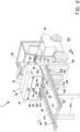
- FIG. 1-5 A schematic overview of a pallet system 1 according to a first embodiment of the invention is shown in Figures 1-5 .
- the pallet system 1 comprises a load 10, a pallet 20, a transport device 30 and a conveyor 40.
- the load 10 is a rectangular-shaped box that comprises a bottom wall 12, a left side wall 13, a right side wall 14 opposite the left side wall 13, a front wall 15, a back wall 16 opposite the front wall 15, and, optionally, a top wall 11 opposite the bottom wall 12.
- the load 10 has a load length L1 between the front wall 15 and the back wall 16, a load width W1 between the left side wall 13 and the right side wall 14, and a load height H1 between the bottom wall 12 and the top wall 11.
- the top slats 21 define a load receiving surface 24 with a rectangular outline for receiving the load 10 thereon.
- the pallet 20 has a pallet width W2, which corresponds to the length of the top slats 21, a pallet height, which is the combined height of the supporting structure 22 and the top slat 21, and a pallet length L2, which corresponds to the length of the supporting structures 22.
- the load 10 is positioned on the pallet 20 by arranging the bottom wall 12 of the load 10 on the load receiving surface 24 of the pallet 20.
- the load 10 projects from the pallet 20 at both sides of the load receiving surface 24 in the longitudinal direction of the top slats 21.
- the load 10 projects from the pallet 20 at the left side wall 13 by a left projecting portion 17 having a left downwardly directed support surface 51 at the bottom wall 12.
- the left projecting portion 17 projects from the pallet 20 by a left projecting distance D1.
- the load 10 projects from the pallet 20 by a right projecting portion 18 having a right downwardly directed support surface 52 at the bottom wall 12.
- the right projecting portion 18 projects from the pallet 20 by a right projecting distance D2.
- the pallet system 1 further comprises a transport device, in this example an electrically driven forklift 30 that is adapted to drive over an underground 100.
- the forklift 30 comprises a forklift body 31, a mast 32 and a carriage 33.
- the carriage 33 is displaceable in a vertical displacement direction or lifting direction V along the mast 32.
- the carriage 33 comprises a fork 34 with two horizontal arranged fork teeth 35.
- the insertion channels 23 of the pallet 20 are configured for receiving the fork teeth 35 of the forklift 30 therein.
- the fork teeth 35 have a fork teeth height that is smaller than the insertion channel height H3 and a fork teeth width that is smaller than the insertion channel width W3, such that the fork teeth 35 can easily be inserted into the insertion channels 23 with margin.
- the forklift 30 is configured to hold the pallet 20 by inserting the two fork teeth 35 into the insertion channels 23 of the pallet 20 and lifting the fork 34 by displacing the carriage 33 upwards in the vertical lifting direction V along the mast
- the pallet system 1 further comprises a horizontally arranged conveyor 40 configured for receiving the load 10 at a receiving end 41 thereof and for transporting the load 10 away from the receiving end 41 in a transport direction T, for example, towards a non-shown delivery end.
- the conveyor 40 comprises a left roller conveyor 42 and a right roller conveyor 43. Both the left roller conveyor 42 and the right roller conveyor 43 comprise a horizontal beam 44 and multiple vertical beams 48, 49 that support the horizontal beams 44.
- the left roller conveyor 42 and the right roller conveyor 43 are spaced from each other so as to create a pallet pass-through opening 46 therebetween having an opening width W4, as best shown in Figures 1 and 3 .
- the left roller conveyor 42 and the right roller conveyor 43 are connected via a connecting beam 47.
- the horizontal beams 44 of the conveyor 40 are provided with rollers 50 thereon.
- Each roller 50 having a roll axis C around which the roller 50 can freely rotate.
- Multiple rollers 50 are arranged on each horizontal beam 44, wherein for each horizontal beam 44 the rollers 50 are arranged side by side with the roll axes C parallel to each other and horizontal arranged, and with the roll axes C being transverse to the longitudinal direction of the horizontal beams 44.
- the left roller conveyor 42 has a left upwardly directed support surface 53 that is formed by the upwardly facing parts of the outline of the rollers 50 that are arranged at the left conveyor 42.
- the left upwardly directed support surface 53 is configured to receive the left downwardly directed support surface 51 of the load 10 thereon.
- the right roller conveyor 43 has a right upwardly directed support surface 54 that is formed by the upwardly facing parts of the outline of the rollers 50 that are arranged at the right roller conveyor 43.
- the right upwardly directed support surface 54 is configured to receive the right downwardly directed support surface 52 of the load 10 thereon.
- Both the left roller conveyor 42, and the right roller conveyor 43 have a conveyor width W5 which corresponds to a length of each roller 50 in axial direction.
- This conveyor width W5 is also corresponding to the width of the left upwardly directed support surface 53 and the right upwardly directed support surface 54.
- the conveyor 40 is configured to receive the load 10 which is transported on the pallet 20 towards the conveyor 40 by the forklift 30.
- the pallet pass-through opening 46 has an opening length L4 extending from the receiving end 41 towards the connecting beam 47, wherein the opening length L4 is larger than the pallet length L2, so that the pallet 20 can be received in and pass through the pallet pass-through opening 46 between the connecting beam 47 and the receiving end 41.
- the opening width W4 is slightly wider than the pallet width W2, so that the pallet 20 can pass through the left roller conveyor 42 and the right roller conveyor 43 via the pallet pass-through opening 46 by margin.
- the conveyor 40 has a conveyor height H4, which conveyor height H4 is at least larger than the pallet height.
- Figure 1 shows the pallet system 1 in the situation wherein the load 10 is provided on the pallet 20, and wherein the pallet 20 is lifted high by the forklift 30.
- the pallet 20 is lifted to a height above the conveyor height H4.
- the forklift 30 drives over the underground 100 towards the conveyor 40 and is received by the conveyor 40 in a horizontal receiving direction R that is parallel to the transport direction T.
- the conveyor 40 is received at the receiving end 41 of the conveyor 40, such that the pallet 20 at the fork 34 of the forklift 30 is aligned with and positioned above the pallet pass-through opening 46, as shown in Figure 2 .
- the pallet 20 which is lifted by the forklift 30 is lowered in the vertical lifting direction V to a height below the conveyor height H4. Since the pallet width W2 is smaller than the opening width W4, the pallet 20 passes through the pallet pass-through opening 46, and since the load width W1 is larger than the opening width W4, the load 10 does not pass through the pallet pass-through opening 46. Therefore, the load 10 is transferred to the conveyor 40 on top of the rollers 50 thereof.
- the left downwardly directed support surface 51 of the load 10 corresponding to the left projecting portion 17 lands on top of the rollers 50 at the left conveyor 42 on the left upwardly directed support surface 53.
- the right downwardly directed support surface 52 of the load 10 lands on top of the rollers 50 at the right conveyor 43 on the right upwardly directed support surface 54.
- the pallet 20 without the load 10 remains at the fork 34 of the forklift 30, as shown in Figures 3 and 4 .
- the forklift 30 drives, over the underground 100, away from the conveyor 40.
- the conveyor 40 is configured for transporting the load 10, that is received thereon, away from the receiving end 41 in a transport direction T, for example towards the non-shown delivery end.
- the left projecting distance D1 of the left projecting portion 17 is at least 5% of the load width W1
- the right projecting distance D2 of the right projecting portion 18 is at least 5% of the load width W1.
- the left projecting distance D1 can differ from the right projecting distance D2.
- the pallet width W2 is at least 50% of the load width W1.
- the roller conveyor width W5 is in this example similar for the left roller conveyor 42 and the right roller conveyor 43, but the roller conveyor width W5 can be different for the left roller conveyor 42 and the right roller conveyor 43.
- the left roller conveyor width W5 and the right roller conveyor width W5 are each at least 5% of the load width W1. Further, the load width W1 minus the left roller conveyor width W5 and minus the right roller conveyor width W5 is at least 10% of the load width W1.
- the pallet width W2 is at least 50% of the load width W1.
- the pallet system 101 comprises a conveyor 140 that is inclined under an inclination angle A.
- An exemplary embodiment of this is shown in Figures 6 and 7 .
- the pallet system 101 comprises, except for some components of the conveyor and the conveyor itself, the same components as the pallet system according to the exemplary embodiment described before. Components that are different compared to the first exemplary embodiment are reintroduced and renumbered in the description and in Figures 6 and 7 .
- the horizontal beams 44 of the conveyor are supported by a first set of vertical beams 148 having a first beam height H41, and a second set of vertical beams 149 having a second beam height H42.
- the first beam height H41 is larger than the second beam height H42, resulting in the horizontal beams 44 being arranged under the inclination angle A.
- the load 10 is provided on the pallet 20, and the pallet 20 is lifted high by the forklift 30.
- the pallet 20 is lifted to a heigh above the first beam height H41.
- the forklift 30 drives over the underground 100 towards the conveyor 140 in the receiving direction R, such that the pallet 20 is aligned with and positioned above the pallet pass-through opening 46, as shown in Figure 6 .
- the pallet 20 which is lifted by the forklift 30 is lowered in the vertical lifting direction V to a height below the first beam height H41. Since the pallet width W2 is smaller than the opening width W4, the pallet passes through the pallet pass-through opening 46, and since the load width W1 is larger than the opening width W4, the load 10 does not pass through the pallet pass-through opening 46. Therefore, the load 10 is transferred to the conveyor 140 on top of the rollers 50 thereof.
- the load 10 tilts by its own weight until its bottom wall 12 is parallel to the transport direction TT of the conveyor 140, as shown in Figure 7 .
- the left projecting portion 17 lands on top of the rollers 50 arranged on the horizontal beam 44 of the left roller conveyor 42 and the right projecting portion 18 lands on top of the rollers 50 arranged on the horizontal beam 44 of the right roller conveyor 43.
- the pallet 20 without the load 10 remains on the fork 34 of the forklift 30.
- the forklift 30 drives over the underground 100, away from the conveyor 140.
- the conveyor 140 is configured for transporting the load 10 away from the receiving end 41 in a transport direction TT towards a non-shown delivery end.
Landscapes
- Engineering & Computer Science (AREA)
- Mechanical Engineering (AREA)
- Transportation (AREA)
- Structural Engineering (AREA)
- Civil Engineering (AREA)
- Life Sciences & Earth Sciences (AREA)
- Geology (AREA)
- Intermediate Stations On Conveyors (AREA)
- Warehouses Or Storage Devices (AREA)
Abstract
Description
- The invention relates to a pallet system for transferring a load from a pallet to a conveyor, the pallet system comprising a load, a pallet for holding the load thereon, a transport device with a lifting device for vertical and horizontal movement of the pallet, and a conveyor for the load.
- The use of pallets for storage of load thereon and/or moving the pallet with the load thereon is well known. By using a forklift or something like that the pallet is easily lifted and displaced between two locations.
-
JP H08 2650 A claim 1. - A disadvantage of the current pallet systems is that in order to transfer a load from a pallet to a conveyor, and thereby separating the load from the pallet, a further transferring device or technique is needed. Pallet unloading is generally performed by gripping the load from above or from the side, for example by a pick-up device or human operator, such that the load is transferred to the conveyor. This system of separating results in the use of extra manpower or equipment, increasing the costs and slowing down the transferring process.
- It is an object of the present invention to ameliorate or to eliminate one or more disadvantages of the known pallet systems, or at least to provide an alternative pallet system.
- According to a first aspect, the invention provides a pallet system for transferring a load from a pallet to a conveyor, the pallet system comprising:
- a load having a bottom with a rectangular outline and a load width,
- a pallet having a pallet width for holding the load, having a load receiving surface for receiving and supporting the bottom of the load thereon,
- a transport device configured for displacing the pallet, wherein the transport device comprises a lifting device that is configured for carrying the pallet and for vertical displacement of the pallet, and
- a conveyor device having a receiving end, wherein the conveyor device is configured for receiving the load at the receiving end thereof and for transporting the load in a transport direction away from the receiving end, wherein the conveyor device comprises a left conveyor and a right conveyor at a conveyor height that are parallelly arranged and spaced from each other at a distance so as to define a pallet pass-through opening therebetween, wherein the pallet pass-through opening has a pallet pass-through opening width,
- wherein the load width is larger than the pallet width so that the load projects from the pallet,
- wherein the load projects from the pallet at two opposite sides of the pallet in the width direction,
- wherein the load has a left projecting portion having a left downwardly directed support surface, wherein the left projecting portion projects from the pallet by a left projecting distance, wherein the load has a right projecting portion having a right downwardly directed support surface, wherein the right projecting portion projects from the pallet by a right projecting distance,
- wherein the load width is larger than the pallet pass-through opening width,
- wherein the pallet width is smaller than the pallet pass-through opening width,
- wherein the left conveyor has a left upwardly directed support surface configured for receiving the left downwardly directed support surface thereon, wherein the right conveyor has a right upwardly directed support surface configured for receiving the right downwardly directed support surface thereon, and
- wherein the left downwardly directed support surface fits on the left upwardly directed support surface, and the right downwardly directed support surface fits on the right upwardly directed support surface when the pallet with the load thereon is lifted through the pallet pass-through opening.
- In the pallet system according to the invention, the load is transferred from the pallet to the conveyor device by the transport device without the need of a pick-up device or a human being. The load is transferred to the conveyor device, and the pallet can directly be moved away from below the load by the transport device. This makes transferring the load from the pallet to the conveyor device, in for example a warehouse, easier, faster, less complex, and cheaper.
- In an embodiment the load receiving surface has a rectangular outline.
- In an embodiment the left projecting distance is at least 5% of the load width, and wherein the right projecting distance is at least 5% of the load width.
- In an embodiment the left upwardly directed support surface has a left conveyor width, and the right upwardly directed support surface has a right conveyor width, wherein the left conveyor width is at least 5% of the load width, wherein the right conveyor width is at least 5% of the load width, and wherein the load width minus the pallet pass-through opening width is at least 10% of the load width.
- In an embodiment the pallet width is at least 50% of the load width.
- In an embodiment the left conveyor and the right conveyor are roller conveyors.
- In an embodiment the left upwardly directed support surface and the right upwardly directed support surface are horizontally arranged.
- In an embodiment the left upwardly directed support surface and the right upwardly directed support surface are arranged at an inclination angle.
- In an embodiment the left upwardly directed support surface and the right upwardly directed support surface slope downwards away from the receiving end.
- In an embodiment the transport device is an automated guided vehicle or forklift.
- In an embodiment the load has a bottom wall, a left side wall, a right side wall opposite the left side wall, a front wall, and a back wall opposite the front wall.
- In an embodiment thereof the load further has a top wall opposite the bottom wall.
- In an embodiment the load is a cardboard box.
- According to a second aspect, the invention provides a method for transferring a load from a pallet to a conveyor using a pallet system according to any of the preceding claims, wherein the method comprises
- by the lifting device, displacing the pallet having the load thereon in a vertical displacement direction above the conveyor height,
- by the transport device, displacing the pallet having the load thereon towards the conveyor device in a receiving direction that is in the vertical projection parallel to the transport direction of the conveyor device,
- by the lifting device, displacing the pallet having the load thereon from a height above the conveyor height, through the pallet pass-through opening, to a height below the conveyor height, such that the left downwardly directed support surface lands on the left upwardly directed support surface and the right downwardly directed support surface lands on the right upwardly directed support surface, and the load is transferred from the pallet while the pallet remains at the lifting device,
- by the transport device, removing the pallet without the load thereon away from the conveyor device.
- The invention will be elucidated on the basis of an exemplary embodiment shown in the attached drawings, in which:
-
Figures 1 - 5 show isometric views of a pallet system in five subsequent steps in its operation according to a first embodiment of the invention. -
Figures 6 - 7 show isometric views of a pallet system in two subsequent steps in its operation according to a second embodiment of the invention. - A schematic overview of a
pallet system 1 according to a first embodiment of the invention is shown inFigures 1-5 . Thepallet system 1 comprises aload 10, apallet 20, atransport device 30 and aconveyor 40. - In this example the
load 10 is a rectangular-shaped box that comprises abottom wall 12, aleft side wall 13, aright side wall 14 opposite theleft side wall 13, afront wall 15, aback wall 16 opposite thefront wall 15, and, optionally, atop wall 11 opposite thebottom wall 12. Theload 10 has a load length L1 between thefront wall 15 and theback wall 16, a load width W1 between theleft side wall 13 and theright side wall 14, and a load height H1 between thebottom wall 12 and thetop wall 11. - As best shown in
Figure 5 , thepallet system 1 comprises a standard rectangular-shaped pallet 20, e.g. a EUR-pallet, that comprises in this example three parallelly arranged supportingstructures 22 and five parallelly arrangedtop slats 21. The supportingstructures 22 are spaced from each other, and thetop slats 21 are transversely arranged on the supportingstructures 22, such that the supportingstructures 22 andtop slats 21 define twoinsertion channels 23 therebetween, as shown inFigure 1 . Theinsertion channels 23 have an insertion channel height H3, which corresponds to the height of the supportingstructures 22, and an insertion channel width W3 which corresponds to a distance at which the supportingstructures 22 are spaced from each other. Thetop slats 21 define aload receiving surface 24 with a rectangular outline for receiving theload 10 thereon. Thepallet 20 has a pallet width W2, which corresponds to the length of thetop slats 21, a pallet height, which is the combined height of the supportingstructure 22 and thetop slat 21, and a pallet length L2, which corresponds to the length of the supportingstructures 22. - The
load 10 is positioned on thepallet 20 by arranging thebottom wall 12 of theload 10 on theload receiving surface 24 of thepallet 20. Theload 10 projects from thepallet 20 at both sides of theload receiving surface 24 in the longitudinal direction of thetop slats 21. Theload 10 projects from thepallet 20 at theleft side wall 13 by a left projectingportion 17 having a left downwardly directedsupport surface 51 at thebottom wall 12. As shown infigure 1 , the left projectingportion 17 projects from thepallet 20 by a left projecting distance D1. At the oppositeright side wall 14, theload 10 projects from thepallet 20 by a right projectingportion 18 having a right downwardly directedsupport surface 52 at thebottom wall 12. The right projectingportion 18 projects from thepallet 20 by a right projecting distance D2. - The
pallet system 1 further comprises a transport device, in this example an electrically drivenforklift 30 that is adapted to drive over an underground 100. Theforklift 30 comprises aforklift body 31, amast 32 and acarriage 33. Thecarriage 33 is displaceable in a vertical displacement direction or lifting direction V along themast 32. Thecarriage 33 comprises afork 34 with two horizontal arrangedfork teeth 35. Theinsertion channels 23 of thepallet 20 are configured for receiving thefork teeth 35 of theforklift 30 therein. Thefork teeth 35 have a fork teeth height that is smaller than the insertion channel height H3 and a fork teeth width that is smaller than the insertion channel width W3, such that thefork teeth 35 can easily be inserted into theinsertion channels 23 with margin. Theforklift 30 is configured to hold thepallet 20 by inserting the twofork teeth 35 into theinsertion channels 23 of thepallet 20 and lifting thefork 34 by displacing thecarriage 33 upwards in the vertical lifting direction V along themast 32. - The
pallet system 1 further comprises a horizontally arrangedconveyor 40 configured for receiving theload 10 at a receivingend 41 thereof and for transporting theload 10 away from the receivingend 41 in a transport direction T, for example, towards a non-shown delivery end. Theconveyor 40 comprises aleft roller conveyor 42 and aright roller conveyor 43. Both theleft roller conveyor 42 and theright roller conveyor 43 comprise ahorizontal beam 44 and multiplevertical beams left roller conveyor 42 and theright roller conveyor 43 are spaced from each other so as to create a pallet pass-throughopening 46 therebetween having an opening width W4, as best shown inFigures 1 and3 . Theleft roller conveyor 42 and theright roller conveyor 43 are connected via a connectingbeam 47. - The
horizontal beams 44 of theconveyor 40 are provided withrollers 50 thereon. Eachroller 50 having a roll axis C around which theroller 50 can freely rotate.Multiple rollers 50 are arranged on eachhorizontal beam 44, wherein for eachhorizontal beam 44 therollers 50 are arranged side by side with the roll axes C parallel to each other and horizontal arranged, and with the roll axes C being transverse to the longitudinal direction of the horizontal beams 44. - The
left roller conveyor 42 has a left upwardly directedsupport surface 53 that is formed by the upwardly facing parts of the outline of therollers 50 that are arranged at theleft conveyor 42. The left upwardly directedsupport surface 53 is configured to receive the left downwardly directedsupport surface 51 of theload 10 thereon. Theright roller conveyor 43 has a right upwardly directedsupport surface 54 that is formed by the upwardly facing parts of the outline of therollers 50 that are arranged at theright roller conveyor 43. The right upwardly directedsupport surface 54 is configured to receive the right downwardly directedsupport surface 52 of theload 10 thereon. - Both the
left roller conveyor 42, and theright roller conveyor 43 have a conveyor width W5 which corresponds to a length of eachroller 50 in axial direction. This conveyor width W5 is also corresponding to the width of the left upwardly directedsupport surface 53 and the right upwardly directedsupport surface 54. - The
conveyor 40 is configured to receive theload 10 which is transported on thepallet 20 towards theconveyor 40 by theforklift 30. The pallet pass-throughopening 46 has an opening length L4 extending from the receivingend 41 towards the connectingbeam 47, wherein the opening length L4 is larger than the pallet length L2, so that thepallet 20 can be received in and pass through the pallet pass-throughopening 46 between the connectingbeam 47 and the receivingend 41. Further, the opening width W4 is slightly wider than the pallet width W2, so that thepallet 20 can pass through theleft roller conveyor 42 and theright roller conveyor 43 via the pallet pass-throughopening 46 by margin. At the receivingend 41 theconveyor 40 has a conveyor height H4, which conveyor height H4 is at least larger than the pallet height. -
Figure 1 shows thepallet system 1 in the situation wherein theload 10 is provided on thepallet 20, and wherein thepallet 20 is lifted high by theforklift 30. Thepallet 20 is lifted to a height above the conveyor height H4. Theforklift 30 drives over the underground 100 towards theconveyor 40 and is received by theconveyor 40 in a horizontal receiving direction R that is parallel to the transport direction T. Theconveyor 40 is received at the receivingend 41 of theconveyor 40, such that thepallet 20 at thefork 34 of theforklift 30 is aligned with and positioned above the pallet pass-throughopening 46, as shown inFigure 2 . - Then the
pallet 20 which is lifted by theforklift 30 is lowered in the vertical lifting direction V to a height below the conveyor height H4. Since the pallet width W2 is smaller than the opening width W4, thepallet 20 passes through the pallet pass-throughopening 46, and since the load width W1 is larger than the opening width W4, theload 10 does not pass through the pallet pass-throughopening 46. Therefore, theload 10 is transferred to theconveyor 40 on top of therollers 50 thereof. - The left downwardly directed
support surface 51 of theload 10 corresponding to theleft projecting portion 17 lands on top of therollers 50 at theleft conveyor 42 on the left upwardly directedsupport surface 53. The right downwardly directedsupport surface 52 of theload 10 lands on top of therollers 50 at theright conveyor 43 on the right upwardly directedsupport surface 54. Thepallet 20 without theload 10 remains at thefork 34 of theforklift 30, as shown inFigures 3 and4 . Lastly, as shown inFigure 5 , theforklift 30 drives, over the underground 100, away from theconveyor 40. - The
conveyor 40 is configured for transporting theload 10, that is received thereon, away from the receivingend 41 in a transport direction T, for example towards the non-shown delivery end. - The left projecting distance D1 of the
left projecting portion 17 is at least 5% of the load width W1, and the right projecting distance D2 of theright projecting portion 18 is at least 5% of the load width W1. The left projecting distance D1 can differ from the right projecting distance D2. The pallet width W2 is at least 50% of the load width W1. - The roller conveyor width W5 is in this example similar for the
left roller conveyor 42 and theright roller conveyor 43, but the roller conveyor width W5 can be different for theleft roller conveyor 42 and theright roller conveyor 43. The left roller conveyor width W5 and the right roller conveyor width W5 are each at least 5% of the load width W1. Further, the load width W1 minus the left roller conveyor width W5 and minus the right roller conveyor width W5 is at least 10% of the load width W1. The pallet width W2 is at least 50% of the load width W1. - In a second embodiment of the pallet system, as shown in
figures 6 and7 , thepallet system 101 comprises aconveyor 140 that is inclined under an inclination angle A. An exemplary embodiment of this is shown inFigures 6 and7 . In the exemplary embodiment, thepallet system 101 comprises, except for some components of the conveyor and the conveyor itself, the same components as the pallet system according to the exemplary embodiment described before. Components that are different compared to the first exemplary embodiment are reintroduced and renumbered in the description and inFigures 6 and7 . - The
horizontal beams 44 of the conveyor are supported by a first set ofvertical beams 148 having a first beam height H41, and a second set ofvertical beams 149 having a second beam height H42. The first beam height H41 is larger than the second beam height H42, resulting in thehorizontal beams 44 being arranged under the inclination angle A. - When the
pallet system 101 is in use, theload 10 is provided on thepallet 20, and thepallet 20 is lifted high by theforklift 30. Thepallet 20 is lifted to a heigh above the first beam height H41. Theforklift 30 drives over the underground 100 towards theconveyor 140 in the receiving direction R, such that thepallet 20 is aligned with and positioned above the pallet pass-throughopening 46, as shown inFigure 6 . - Then the
pallet 20 which is lifted by theforklift 30 is lowered in the vertical lifting direction V to a height below the first beam height H41. Since the pallet width W2 is smaller than the opening width W4, the pallet passes through the pallet pass-throughopening 46, and since the load width W1 is larger than the opening width W4, theload 10 does not pass through the pallet pass-throughopening 46. Therefore, theload 10 is transferred to theconveyor 140 on top of therollers 50 thereof. - The parts of the left downwardly directed
support surface 51 and the right downwardly directedsupport surface 52 of theload 10 that are closest to theback wall 16 touch therollers 50 of theconveyor 140 first at the parts of the left upwardly directedsupport surface 53 and the right upwardly directedsupport surface 54 that are closest to the receivingend 41. - When the
pallet 10 is further lifted downwards theload 10 tilts by its own weight until itsbottom wall 12 is parallel to the transport direction TT of theconveyor 140, as shown inFigure 7 . Theleft projecting portion 17 lands on top of therollers 50 arranged on thehorizontal beam 44 of theleft roller conveyor 42 and theright projecting portion 18 lands on top of therollers 50 arranged on thehorizontal beam 44 of theright roller conveyor 43. Thepallet 20 without theload 10 remains on thefork 34 of theforklift 30. Lastly, theforklift 30 drives over the underground 100, away from theconveyor 140. - The
conveyor 140 is configured for transporting theload 10 away from the receivingend 41 in a transport direction TT towards a non-shown delivery end.
Claims (14)
- Pallet system (1, 101) for transferring a load (10) from a pallet (20) to a conveyor (40, 140), the pallet system (1, 101) comprising:a load (10) having a bottom (12) with a rectangular outline and a load width (W1),a pallet (20) having a pallet width (W2) for holding the load (10), having a load receiving surface (24) for receiving and supporting the bottom (12) of the load (10) thereon,a transport device (30) configured for displacing the pallet (20), wherein the transport device (30) comprises a lifting device (33) that is configured for carrying the pallet (20) and for vertical displacement of the pallet (20), anda conveyor device (40, 140) having a receiving end (41), wherein the conveyor device (40, 140) is configured for receiving the load (10) at the receiving end (41) thereof and for transporting the load (10) in a transport direction (T, TT) away from the receiving end (41), wherein the conveyor device (40, 140) comprises a left conveyor (42) and a right conveyor (43) at a conveyor height (H4, H41) that are parallelly arranged and spaced from each other at a distance so as to define a pallet pass-through opening (46) therebetween, wherein the pallet pass-through opening (46) has a pallet pass-through opening width (W4), characterized in that the load width (W1) is larger than the pallet width (W2) so that the load (10) projects from the pallet (20),wherein the load (10) projects from the pallet (20) at two opposite sides of the pallet (20) in the width direction,wherein the load (10) has a left projecting portion (17) having a left downwardly directed support surface (51), wherein the left projecting portion (17) projects from the pallet (20) by a left projecting distance (D1), wherein the load (10) has a right projecting portion (18) having a right downwardly directed support surface (52), wherein the right projecting portion (18) projects from the pallet (20) by a right projecting distance (D2),wherein the load width (W1) is larger than the pallet pass-through opening width (W4),wherein the pallet width (W2) is smaller than the pallet pass-through opening width (W4),wherein the left conveyor (42) has a left upwardly directed support surface (53) configured for receiving the left downwardly directed support surface (51) thereon, wherein the right conveyor (43) has a right upwardly directed support surface (54) configured for receiving the right downwardly directed support surface (52) thereon, andwherein the left downwardly directed support surface (51) fits on the left upwardly directed support surface (53), and the right downwardly directed support surface (52) fits on the right upwardly directed support surface (54) when the pallet (20) with the load (10) thereon is lifted through the pallet pass-through opening (46) .
- Pallet system (1, 101) according to claim 1, wherein the load receiving surface (24) has a rectangular outline.
- Pallet system (1, 101) according to any of the preceding claims, wherein the left projecting distance (D1) is at least 5% of the load width (W1), and wherein the right projecting distance (D2) is at least 5% of the load width (W1).
- Pallet system (1, 101) according to any of the preceding claims, wherein the left upwardly directed support surface (53) has a left conveyor width (W5), and the right upwardly directed support surface (53) has a right conveyor width (W5), wherein the left conveyor width (W5) is at least 5% of the load width (W1), wherein the right conveyor width (W5) is at least 5% of the load width (W1), and wherein the load width (W1) minus the pallet pass-through opening width (W4) is at least 10% of the load width (W1).
- Pallet system (1, 101) according to any of the preceding claims, wherein the pallet width (W2) is at least 50% of the load width (W1).
- Pallet system (1, 101) according to any of the preceding claims, wherein the left conveyor (42) and the right conveyor (43) are roller conveyors.
- Pallet system (1) according to any of the preceding claims, wherein the left upwardly directed support surface (53) and the right upwardly directed support surface (54) are horizontally arranged.
- Pallet system (101) according to any of claims 1-6, wherein the left upwardly directed support surface (53) and the right upwardly directed support surface (54) are arranged at an inclination angle (A).
- Pallet system (101) according to claim 8, wherein the left upwardly directed support surface (53) and the right upwardly directed support surface (54) slope downwards away from the receiving end (41).
- Pallet system (1, 101) according to any of the preceding claims, wherein the transport device (30) is an automated guided vehicle or forklift.
- Pallet system (1, 101) according to any of the preceding claims, wherein the load (10) has a bottom wall (12), a left side wall (13), a right side wall (14) opposite the left side wall (13), a front wall (15), and a back wall (16) opposite the front wall (15).
- Pallet system (1, 101) according to claim 11, wherein the load (10) further has a top wall (11) opposite the bottom wall (12).
- Pallet system (1, 101) according to any of the preceding claims, wherein the load (10) is a cardboard box.
- Method for transferring a load (10) from a pallet (20) to a conveyor (40, 140) using a pallet system (1, 101) according to any of the preceding claims, wherein the method comprisesby the lifting device (33), displacing the pallet (20) having the load (10) thereon in a vertical displacement direction (V) above the conveyor height (H4, H41),by the transport device (30), displacing the pallet (20) having the load (10) thereon towards the conveyor device (40, 140) in a receiving direction (R) that is in the vertical projection parallel to the transport direction (T, TT) of the conveyor device (40, 140),by the lifting device (33), displacing the pallet (20) having the load (10) thereon from a height above the conveyor height (H4, H41), through the pallet pass-through opening (46), to a height below the conveyor height (H4, H41), such that the left downwardly directed support surface (51) lands on the left upwardly directed support surface (52) and the right downwardly directed support surface (53) lands on the right upwardly directed support surface (54), and the load (10) is transferred from the pallet (20) while the pallet (20) remains at the lifting device (33),by the transport device (30), removing the pallet (20) without the load (10) thereon away from the conveyor device (40, 140).
Applications Claiming Priority (1)
| Application Number | Priority Date | Filing Date | Title |
|---|---|---|---|
| NL2035671A NL2035671B1 (en) | 2023-08-24 | 2023-08-24 | Pallet system |
Publications (3)
| Publication Number | Publication Date |
|---|---|
| EP4512748A1 true EP4512748A1 (en) | 2025-02-26 |
| EP4512748B1 EP4512748B1 (en) | 2025-12-31 |
| EP4512748C0 EP4512748C0 (en) | 2025-12-31 |
Family
ID=88207216
Family Applications (1)
| Application Number | Title | Priority Date | Filing Date |
|---|---|---|---|
| EP24188357.8A Active EP4512748B1 (en) | 2023-08-24 | 2024-07-12 | PALLET SYSTEM |
Country Status (4)
| Country | Link |
|---|---|
| EP (1) | EP4512748B1 (en) |
| ES (1) | ES3058643T3 (en) |
| NL (1) | NL2035671B1 (en) |
| PL (1) | PL4512748T3 (en) |
Citations (3)
| Publication number | Priority date | Publication date | Assignee | Title |
|---|---|---|---|---|
| JPH082650A (en) | 1994-06-15 | 1996-01-09 | Mitsui Eng & Shipbuild Co Ltd | Conveyor baggage packing method and accumulation conveyor system |
| EP4071093A1 (en) * | 2021-04-07 | 2022-10-12 | Interroll Holding AG | Dock station arrangement and method for transferring goods between a conveyor device and a transport vehicle |
| EP4071089A1 (en) * | 2021-04-07 | 2022-10-12 | Interroll Holding AG | Conveyor arrangement |
-
2023
- 2023-08-24 NL NL2035671A patent/NL2035671B1/en active
-
2024
- 2024-07-12 ES ES24188357T patent/ES3058643T3/en active Active
- 2024-07-12 PL PL24188357.8T patent/PL4512748T3/en unknown
- 2024-07-12 EP EP24188357.8A patent/EP4512748B1/en active Active
Patent Citations (3)
| Publication number | Priority date | Publication date | Assignee | Title |
|---|---|---|---|---|
| JPH082650A (en) | 1994-06-15 | 1996-01-09 | Mitsui Eng & Shipbuild Co Ltd | Conveyor baggage packing method and accumulation conveyor system |
| EP4071093A1 (en) * | 2021-04-07 | 2022-10-12 | Interroll Holding AG | Dock station arrangement and method for transferring goods between a conveyor device and a transport vehicle |
| EP4071089A1 (en) * | 2021-04-07 | 2022-10-12 | Interroll Holding AG | Conveyor arrangement |
Also Published As
| Publication number | Publication date |
|---|---|
| PL4512748T3 (en) | 2026-03-30 |
| ES3058643T3 (en) | 2026-03-12 |
| EP4512748B1 (en) | 2025-12-31 |
| NL2035671B1 (en) | 2025-03-06 |
| EP4512748C0 (en) | 2025-12-31 |
Similar Documents
| Publication | Publication Date | Title |
|---|---|---|
| CN106477217B (en) | Article carrying apparatus | |
| JP2023517014A (en) | Loading/unloading device, loading/unloading system and loading/unloading method | |
| US4568231A (en) | Method and equipment for palletizing and depalletizing can-tops | |
| CN210084502U (en) | Intelligent cargo handling system | |
| CN105151613A (en) | Lifting-stacking type automatic stereoscopic storehouse | |
| CN112124981B (en) | Feeding device and feeding method thereof | |
| CN111422412B (en) | Production line capable of realizing separation of building blocks and supporting plates and stacking of building blocks | |
| CN113979154A (en) | Automatic loading system and loading method for carton packaging materials of flat car | |
| WO2025145869A1 (en) | Automatic material loading system | |
| KR20240032074A (en) | How to store or retrieve storage aids | |
| JP2692414B2 (en) | Equipment for loading and unloading trays | |
| CN213801957U (en) | Feeding device | |
| CN111003440B (en) | Conveying equipment | |
| EP4512748B1 (en) | PALLET SYSTEM | |
| JP2000169018A (en) | Device for reloading sheet pile on first pallet onto second pallet | |
| JP2008024493A (en) | Article transfer device | |
| CN114074852B (en) | Cage loading device and cage loading system for cage truck | |
| CN215945979U (en) | AGV conveying equipment and AGV logistics system | |
| JPH10181884A (en) | Article stacking method and apparatus | |
| US6099240A (en) | Method and apparatus for handling sheet stacks | |
| CN111620013A (en) | Stacker, get and put equipment and stereoscopic warehouse | |
| US12151899B2 (en) | Hauling transporter, hauling beam and method for loading | |
| CN214780516U (en) | Automatic loading and unloading all-in-one | |
| KR102736753B1 (en) | Palletizer in which the pallet loaded with the product is ready to be discharged in close contact with the ground | |
| CN211308680U (en) | Cart and transport device |
Legal Events
| Date | Code | Title | Description |
|---|---|---|---|
| PUAI | Public reference made under article 153(3) epc to a published international application that has entered the european phase |
Free format text: ORIGINAL CODE: 0009012 |
|
| STAA | Information on the status of an ep patent application or granted ep patent |
Free format text: STATUS: THE APPLICATION HAS BEEN PUBLISHED |
|
| AK | Designated contracting states |
Kind code of ref document: A1 Designated state(s): AL AT BE BG CH CY CZ DE DK EE ES FI FR GB GR HR HU IE IS IT LI LT LU LV MC ME MK MT NL NO PL PT RO RS SE SI SK SM TR |
|
| STAA | Information on the status of an ep patent application or granted ep patent |
Free format text: STATUS: REQUEST FOR EXAMINATION WAS MADE |
|
| 17P | Request for examination filed |
Effective date: 20250324 |
|
| GRAP | Despatch of communication of intention to grant a patent |
Free format text: ORIGINAL CODE: EPIDOSNIGR1 |
|
| STAA | Information on the status of an ep patent application or granted ep patent |
Free format text: STATUS: GRANT OF PATENT IS INTENDED |
|
| RIC1 | Information provided on ipc code assigned before grant |
Ipc: B66F 9/06 20060101ALI20250523BHEP Ipc: B65G 65/00 20060101ALI20250523BHEP Ipc: B65G 47/52 20060101ALI20250523BHEP Ipc: B65G 37/00 20060101ALI20250523BHEP Ipc: B65G 13/11 20060101AFI20250523BHEP |
|
| INTG | Intention to grant announced |
Effective date: 20250606 |
|
| GRAS | Grant fee paid |
Free format text: ORIGINAL CODE: EPIDOSNIGR3 |
|
| GRAA | (expected) grant |
Free format text: ORIGINAL CODE: 0009210 |
|
| STAA | Information on the status of an ep patent application or granted ep patent |
Free format text: STATUS: THE PATENT HAS BEEN GRANTED |
|
| AK | Designated contracting states |
Kind code of ref document: B1 Designated state(s): AL AT BE BG CH CY CZ DE DK EE ES FI FR GB GR HR HU IE IS IT LI LT LU LV MC ME MK MT NL NO PL PT RO RS SE SI SK SM TR |
|
| REG | Reference to a national code |
Ref country code: CH Ref legal event code: F10 Free format text: ST27 STATUS EVENT CODE: U-0-0-F10-F00 (AS PROVIDED BY THE NATIONAL OFFICE) Effective date: 20251231 Ref country code: GB Ref legal event code: FG4D |
|
| REG | Reference to a national code |
Ref country code: CH Ref legal event code: R17 Free format text: ST27 STATUS EVENT CODE: U-0-0-R10-R17 (AS PROVIDED BY THE NATIONAL OFFICE) Effective date: 20260109 |
|
| REG | Reference to a national code |
Ref country code: DE Ref legal event code: R096 Ref document number: 602024001919 Country of ref document: DE |
|
| REG | Reference to a national code |
Ref country code: IE Ref legal event code: FG4D |
|
| U01 | Request for unitary effect filed |
Effective date: 20260106 |
|
| U07 | Unitary effect registered |
Designated state(s): AT BE BG DE DK EE FI FR IT LT LU LV MT NL PT RO SE SI Effective date: 20260113 |
|
| REG | Reference to a national code |
Ref country code: ES Ref legal event code: FG2A Ref document number: 3058643 Country of ref document: ES Kind code of ref document: T3 Effective date: 20260312 |
|
| PG25 | Lapsed in a contracting state [announced via postgrant information from national office to epo] |
Ref country code: HR Free format text: LAPSE BECAUSE OF FAILURE TO SUBMIT A TRANSLATION OF THE DESCRIPTION OR TO PAY THE FEE WITHIN THE PRESCRIBED TIME-LIMIT Effective date: 20251231 |
|
| PG25 | Lapsed in a contracting state [announced via postgrant information from national office to epo] |
Ref country code: RS Free format text: LAPSE BECAUSE OF FAILURE TO SUBMIT A TRANSLATION OF THE DESCRIPTION OR TO PAY THE FEE WITHIN THE PRESCRIBED TIME-LIMIT Effective date: 20260331 |