EP4512742A1 - Dispensing apparatus - Google Patents
Dispensing apparatus Download PDFInfo
- Publication number
- EP4512742A1 EP4512742A1 EP24184060.2A EP24184060A EP4512742A1 EP 4512742 A1 EP4512742 A1 EP 4512742A1 EP 24184060 A EP24184060 A EP 24184060A EP 4512742 A1 EP4512742 A1 EP 4512742A1
- Authority
- EP
- European Patent Office
- Prior art keywords
- configuration
- delivery member
- baffle
- dispensing
- carrying holder
- Prior art date
- Legal status (The legal status is an assumption and is not a legal conclusion. Google has not performed a legal analysis and makes no representation as to the accuracy of the status listed.)
- Pending
Links
Images


Classifications
-
- A—HUMAN NECESSITIES
- A61—MEDICAL OR VETERINARY SCIENCE; HYGIENE
- A61J—CONTAINERS SPECIALLY ADAPTED FOR MEDICAL OR PHARMACEUTICAL PURPOSES; DEVICES OR METHODS SPECIALLY ADAPTED FOR BRINGING PHARMACEUTICAL PRODUCTS INTO PARTICULAR PHYSICAL OR ADMINISTERING FORMS; DEVICES FOR ADMINISTERING FOOD OR MEDICINES ORALLY; BABY COMFORTERS; DEVICES FOR RECEIVING SPITTLE
- A61J1/00—Containers specially adapted for medical or pharmaceutical purposes
- A61J1/03—Containers specially adapted for medical or pharmaceutical purposes for pills or tablets
-
- A—HUMAN NECESSITIES
- A61—MEDICAL OR VETERINARY SCIENCE; HYGIENE
- A61J—CONTAINERS SPECIALLY ADAPTED FOR MEDICAL OR PHARMACEUTICAL PURPOSES; DEVICES OR METHODS SPECIALLY ADAPTED FOR BRINGING PHARMACEUTICAL PRODUCTS INTO PARTICULAR PHYSICAL OR ADMINISTERING FORMS; DEVICES FOR ADMINISTERING FOOD OR MEDICINES ORALLY; BABY COMFORTERS; DEVICES FOR RECEIVING SPITTLE
- A61J7/00—Devices for administering medicines orally, e.g. spoons; Pill counting devices; Arrangements for time indication or reminder for taking medicine
- A61J7/0076—Medicament distribution means
-
- B—PERFORMING OPERATIONS; TRANSPORTING
- B65—CONVEYING; PACKING; STORING; HANDLING THIN OR FILAMENTARY MATERIAL
- B65D—CONTAINERS FOR STORAGE OR TRANSPORT OF ARTICLES OR MATERIALS, e.g. BAGS, BARRELS, BOTTLES, BOXES, CANS, CARTONS, CRATES, DRUMS, JARS, TANKS, HOPPERS, FORWARDING CONTAINERS; ACCESSORIES, CLOSURES, OR FITTINGS THEREFOR; PACKAGING ELEMENTS; PACKAGES
- B65D83/00—Containers or packages with special means for dispensing contents
- B65D83/04—Containers or packages with special means for dispensing contents for dispensing annular, disc-shaped, spherical or like small articles, e.g. tablets or pills
- B65D83/0409—Containers or packages with special means for dispensing contents for dispensing annular, disc-shaped, spherical or like small articles, e.g. tablets or pills the dispensing means being adapted for delivering one article, or a single dose, upon each actuation
-
- B—PERFORMING OPERATIONS; TRANSPORTING
- B65—CONVEYING; PACKING; STORING; HANDLING THIN OR FILAMENTARY MATERIAL
- B65D—CONTAINERS FOR STORAGE OR TRANSPORT OF ARTICLES OR MATERIALS, e.g. BAGS, BARRELS, BOTTLES, BOXES, CANS, CARTONS, CRATES, DRUMS, JARS, TANKS, HOPPERS, FORWARDING CONTAINERS; ACCESSORIES, CLOSURES, OR FITTINGS THEREFOR; PACKAGING ELEMENTS; PACKAGES
- B65D85/00—Containers, packaging elements or packages, specially adapted for particular articles or materials
- B65D85/60—Containers, packaging elements or packages, specially adapted for particular articles or materials for sweets or like confectionery products
-
- B—PERFORMING OPERATIONS; TRANSPORTING
- B65—CONVEYING; PACKING; STORING; HANDLING THIN OR FILAMENTARY MATERIAL
- B65D—CONTAINERS FOR STORAGE OR TRANSPORT OF ARTICLES OR MATERIALS, e.g. BAGS, BARRELS, BOTTLES, BOXES, CANS, CARTONS, CRATES, DRUMS, JARS, TANKS, HOPPERS, FORWARDING CONTAINERS; ACCESSORIES, CLOSURES, OR FITTINGS THEREFOR; PACKAGING ELEMENTS; PACKAGES
- B65D2583/00—Containers or packages with special means for dispensing contents
- B65D2583/04—For dispensing annular, disc-shaped or spherical or like small articles or tablets
- B65D2583/0404—Indications, e.g. directions for use
- B65D2583/0422—Indications, e.g. directions for use of variable doses of the same articles
-
- B—PERFORMING OPERATIONS; TRANSPORTING
- B65—CONVEYING; PACKING; STORING; HANDLING THIN OR FILAMENTARY MATERIAL
- B65D—CONTAINERS FOR STORAGE OR TRANSPORT OF ARTICLES OR MATERIALS, e.g. BAGS, BARRELS, BOTTLES, BOXES, CANS, CARTONS, CRATES, DRUMS, JARS, TANKS, HOPPERS, FORWARDING CONTAINERS; ACCESSORIES, CLOSURES, OR FITTINGS THEREFOR; PACKAGING ELEMENTS; PACKAGES
- B65D2583/00—Containers or packages with special means for dispensing contents
- B65D2583/04—For dispensing annular, disc-shaped or spherical or like small articles or tablets
- B65D2583/0472—For dispensing annular, disc-shaped or spherical or like small articles or tablets characterised by the dispensing action
- B65D2583/0477—For dispensing annular, disc-shaped or spherical or like small articles or tablets characterised by the dispensing action the container is maintained in the same position during the dispensing of several successive articles or doses
- B65D2583/0481—One reciprocating action, e.g. to or from
Definitions
- the present disclosure relates generally to a pocket dispensing apparatus which is able to dispense different desired sizes or pieces of small items such as candy, chewing gum, mint, chocolate bin, tablets or pills etc.
- aspects of the disclosure relate to a pocket dispensing apparatus which is able to dispense different desired sizes or pieces of small items such as candy, chewing gum, mint, chocolate bin, tablets or pills etc., which includes various features.
- the adjust apparatus control button can hide in the dispenser in the stowed configuration and be out of the dispenser in the dispensing configuration for consumer to change the dimension of carrying holder.
- the present disclose use some means to decrease the length of a delivering structure in the stowed configuration, such as use the elastic material, roll up configuration, layers pile up, or multiple continuing folds baffle or the like, etc.
- aspects of the disclosure relate to an apparatus configured to dispense one or more small items, the apparatus including a container having a storage chamber configured to hold the one or more small items, and a delivery member including a carrying holder and a control apparatus, where the delivery member is configured to move in a reciprocating motion between a stowed configuration and a dispensing configuration by exertion of an exterior force.
- the control apparatus is configured to be engaged by a user to adjust at least one dimension of the carrying holder.
- the carrying holder and the control apparatus When the delivery member is in the stowed configuration, the carrying holder and the control apparatus are positioned within the container, and when the delivery member is in the dispensing configuration, the carrying holder and the control apparatus are positioned outside of the container so that the user can engage the control apparatus to adjust the at least one dimension of the carrying holder.
- the apparatus also includes a funnel apparatus positioned within the container.
- the funnel apparatus is configured to permit the one or more small items to move through the funnel apparatus into the carrying holder of the delivery member.
- the delivery member further includes a push button configured for pushing the delivery member to the dispensing configuration.
- the dispensing apparatus includes a holder adjusting apparatus, and the control apparatus engages the holder adjusting apparatus to adjust the at least one dimension of the carrying holder.
- the apparatus includes a biasing mechanism biasing the delivery member to the stowed position.
- Additional aspects of the disclosure relate to an apparatus configured to dispense one or more small items, the apparatus including a container having a storage chamber configured to hold the one or more small items, and a delivery member including a carrying holder and a control apparatus.
- the delivery member is configured to move in a reciprocating motion between a stowed configuration and a dispensing configuration.
- the control apparatus is configured for adjusting at least one dimension of the carrying holder when an exterior force is exerted on the control apparatus.
- the carrying holder is formed by two or more parts, and the control apparatus is configured to engage the carrying holder to adjust the at least one dimension of the carrying holder.
- At least a portion of the carrying holder is formed by an elastic material, and the control apparatus engages the carrying holder to adjust the at least one dimension of the carrying holder.
- a dispensing apparatus configured to dispense one or more small items
- the apparatus including a container having a storage chamber configured to hold the one or more small items, a delivery member including a carrying holder, and a baffle apparatus.
- the delivery member is configured to move in a reciprocating motion between a stowed configuration and a dispensing configuration.
- the baffle apparatus is configured to follow the carrying holder such that when the delivery member moves from the stowed configuration to the dispensing configuration, the baffle apparatus is configured to extend to a long configuration, and when the delivery member moves from the dispensing configuration to the stowed configuration, the baffle apparatus is configured to retract to a short configuration.
- the apparatus includes a funnel apparatus positioned within the container.
- the funnel apparatus is configured to permit the one or more small items to move through the funnel apparatus into the carrying holder of the delivery member.
- the delivery member also includes a push button configured for pushing the delivery member to the dispensing configuration.
- the apparatus includes a cover hingedly coupled to the storage chamber, where opening the cover allows for refilling the one or more small items into the storage chamber.
- the baffle apparatus is configured for extending and retracting by: expanding and contracting in length elastically, rolling and unrolling, folding and unfolding, or sliding, among other mechanisms.
- an apparatus configured to dispense one or more small items
- the apparatus including a container having a storage chamber configured to hold the one or more small items and an exit opening in communication with the storage chamber, and a delivery member including a carrying holder configured for receiving the one or small items, an adjusting apparatus configured to move between a plurality of positions to adjust at least one dimension of the carrying holder, and a control apparatus connected to the adjusting apparatus and configured to be engaged by a user to move the adjusting apparatus between the plurality of positions.
- the delivery member is configured to move in a reciprocating motion between a stowed configuration, where the carrying holder is within the container and configured to receive the one or more small items from the storage chamber, and a dispensing configuration, where the delivery member extends through the exit opening and the carrying holder is configured to dispense the one or more small items, by exertion of an exterior force by the user.
- the carrying holder and the control apparatus when the delivery member is in the stowed configuration, the carrying holder and the control apparatus are positioned within the container, and when the delivery member is in the dispensing configuration, the carrying holder and the control apparatus are positioned outside of the container so that the user can engage the control apparatus to adjust the at least one dimension of the carrying holder.
- an apparatus configured to dispense one or more small items
- the apparatus including a container having a storage chamber configured to hold the one or more small items, and an exit opening in communication with the storage chamber, and a delivery member including a carrying holder configured for receiving the one or small items.
- the delivery member is configured to move in a reciprocating motion between a stowed configuration, where the carrying holder is within the container and configured to receive the one or more small items from the storage chamber, and a dispensing configuration, where the delivery member extends through the exit opening and the carrying holder is configured to dispense the one or more small items, by exertion of an exterior force by the user.
- the apparatus further includes a baffle apparatus having a first portion connected to the delivery member and a second portion connected to the container, where the first portion is connected to the delivery member and configured to follow the delivery member, such that when the delivery member moves from the stowed configuration to the dispensing configuration, the baffle apparatus is configured to extend to a long configuration, and when the delivery member moves from the dispensing configuration to the stowed configuration, the baffle apparatus is configured to retract to a short configuration.
- the baffle apparatus is configured for extending and retracting by: expanding and contracting in length elastically, rolling and unrolling, folding and unfolding, or sliding, among other mechanisms.
- an apparatus configured to dispense one or more small items
- the apparatus including a container having a storage chamber configured to hold the one or more small items and an exit opening in communication with the storage chamber, and a delivery member including a carrying holder configured for receiving the one or small items, an adjusting apparatus configured to move between a plurality of positions to adjust at least one dimension of the carrying holder.
- the delivery member is configured to move in a reciprocating motion between a stowed configuration, where the carrying holder is within the container and configured to receive the one or more small items from the storage chamber, and a dispensing configuration, where the delivery member extends through the exit opening and the carrying holder is configured to dispense the one or more small items, by exertion of an exterior force by the user.
- a dispenser apparatus may comprise a delivering structure and a housing.
- the delivering structure may comprise a carrying holder and a baffle apparatus which connect the carrying holder.
- the delivering structure In a non-use or stowed configuration, the delivering structure may be situated in the housing, whereas in a use or dispensing configuration, a carrying holder of the delivering structure is moved out of the housing for dispensing tablets or pills.
- a holder exit may be disposed on the housing, and the delivering structure may reciprocate between the stowed configuration and the dispensing configuration through the holder exit.
- the delivering structure may comprise an adjusting apparatus which may be configured to change at least one dimension of the carrying holder.
- the adjusting apparatus may comprise a control apparatus which is situated in the housing when in the stowed configuration.
- the control apparatus of the adjusting apparatus may move out of the housing through the holder exit with the carrying holder from the stowed configuration to the dispensing configuration for consumer actuating it to change the dimension of the carrying holder, and the control apparatus may retreat back into housing with the carrying holder through the holder exit from the dispensing configuration to the stowed configuration.
- the carrying holder may be formed by two pieces of apparatus, and each piece of apparatus may seem like part of the carrying holder, and these two pieces of apparatus partly pile up together to form the carrying holder, a control apparatus may engage the two pieces of apparatus to change the dimension of the carrying holder.
- part of the carrying holder sidewalls may be formed of the elastic or flexible material, such as soft plastic any rubber, etc. and a control apparatus may engage the elastic and flexible sidewalls of the carrying holder to extend or contract to change the dimension of the carrying holder.
- a funnel apparatus and the baffle apparatus of the delivering structure, or the funnel apparatus and a barrier apparatus, or the funnel apparatus and part of the baffle apparatus of the delivering structure and the barrier apparatus are defined between two opposite sides of the dispenser apparatus, and they may divide the housing into an upper chamber and a lower chamber.
- the upper chamber may be used as a storage chamber to storage the tablets or pills
- the lower chamber may be as the rest chamber and the delivering structure is situated in the rest chamber when in the stowed configuration.
- the baffle apparatus of the delivering structure may direct the tablets or pills from the storage chamber through the funnel apparatus into the carrying holder of the delivering structure in the stowed configuration.
- the baffle apparatus of the delivering structure may contract, roll up, folded or pile up etc. in the stowed configuration and may extend or stretch or unfold etc. when an external force actuates the delivering structure to move from the stowed position to the dispensing position.
- part of the baffle apparatus may be formed of the elastic and flexible material, such as soft plastic, any rubber, thin metal, nature or synthetic material etc., when an external force engages the delivering structure, and the baffle apparatus may extend to the dispensing position, and when the external force is moved it may contact back to the stowed configuration.
- the baffle apparatus can be disposed of a roll up configuration, like the self-retracting measure tape, one distal tip connect the carrying holder, another distal tip disposed on the dispenser, and other part may be rolled up, when an external force engages the delivering structure, the baffle apparatus may stretch to the dispensing position, and when the external force is removed the baffle apparatus may roll back and engage the carrying holder retreat back to the stowed position.
- the baffle apparatus may be configured like a multi slid doors, two or more parts of the baffle apparatus may pile up together in the stowed position, and slide stretch to the dispensing position.
- the baffle apparatus may be configured like an accordion door, which may be continuing folded together in the stowed position and stretch in the dispensing position.
- the funnel apparatus may comprise several transverse or obliquely vertical or slope bodies positioned on at least one side of the housing, and which are disposed between the storage chamber and the carrying holder so as to facilitate rolling or other movement of the tablets or pills from the storage chamber into the carrying holder fluently or in alignment in the stowed configuration. Additionally, at least one side of the dispenser apparatus may be curved to form the funnel apparatus between the storage chamber and the carrying holder of the delivering structure so as to facilitate transfer of the tablets or pills roll from the storage chamber into the carrying holder fluently or in alignment in the stowed configuration. Furtherly, the funnel apparatus may be disposed by a decline plate disposed on one side or both sides of the dispenser apparatus.
- a button connected to the delivering structure has a first detent or other means to prevent the delivering structure from unintended movement in the stowed configuration, and a second detent or other means to halt the delivering structure at the dispensing position to actuate the control apparatus to adjust the dimension of the carrying holder for carrying different desired sizes or pieces of the tablets and pills.
- a thin layer of soft plastic, rubber, nature or synthetic material etc. may be coated or sprayed on the inside of the dispenser.
- the dispenser apparatus may be formed from any suitable material, such as but not limited to plastic, synthetic, metal, rubber, natural or any other suitable materials, and the dispenser apparatus may be transparent or opaque.
- FIG. 1 illustrates the dispenser apparatus 6 in a dispensing configuration.
- the dispenser apparatus 6 may include a delivering structure 10 and a housing 8 at least partially enclosing the delivering structure 10.
- the housing 8 may be formed by single or multiple elements separately or integrally formed.
- the housing 8 may have a front cover 11 and a back cover 9, a top 12 and a bottom 14, a right end wall 16 and a left end wall 18.
- a corner 20 between the left end wall 18 and the top 12 may be rounded, cut or the like, etc., which may prevent the dispenser apparatus 6 from colliding with a user's mouth when the user retrieves tablets or pills from the dispenser apparatus 6.
- the housing 8 may have other suitable configurations that permit the functionality described herein.
- the housing 8 may be configured as a cube, sphere, cylinder, etc.
- the housing may be configured in the shape of an animal, cartoon character, etc., which may attract the attention of a child or other user.
- a holder exit 28 is configured on the left wall 18 adjacent the bottom 14.
- the delivering structure 10 may be configured for reciprocating motion between a stowed configuration (see FIG. 2 ) and the dispensing configuration through the holder exit 28.
- a push button 50 may be formed with or otherwise operatively coupled to the delivering structure 10, such that a user may push the button 50 forward to engage the delivering structure 10 to move it from the stowed configuration to the dispensing configuration.
- an adjusting plate 26 may be disposed proximate the holder exit 28, and a push button 52 may engage the adjusting plate 26 to move the plate 26 up or down for changing the dimension of the holder exit 28, e.g., to prevent extraneous tablets or pills 68 from rolling out of the holder exit 28 when a user operates the apparatus 6.
- ridges or stripes 38 may be configured on the top 12 of the housing 8.
- the ridges 38 may be formed as an over-molded element having a softer or lower durometer hardness than the housing 8, and it is to be understood that the ridges 38 may have any configuration that provides the intended functionality.
- the ridges 38 may be sinusoidal, may be comprised of a plurality of touching linear segments, etc.
- the dispenser apparatus 6 is in a stowed configuration, with the delivering structure 10 positioned in the housing 8.
- the push button 50 and the groove 69 may have a first detent or other means 58 (see FIG. 1 ) and a second detent or other means 59.
- the first detent 58 is used to prevent the delivering structure 10 from unintended movement when the dispenser apparatus is in the stowed configuration.
- the push button 50 may be pushed up along the detent means 58 to a lock position so that the delivering structure 10 cannot be engaged.
- the push button 50 When the delivering structure 10 is desired to be actuated, the push button 50 then may be pushed down to the unlock position, separating the push button 50 from the detent 58.
- the second detent 59 is used for halt the delivering structure 10 at the dispensing configuration.
- the dispenser apparatus 6 may have a lid 55 disposed on the back cover 9 of the housing 8 and may be hinged on the top 12 of the housing 8.
- the lid 55 In FIG. 3A , the lid 55 is in a closed position. In FIG. 3B , the lid 55 is in an open position. Thus, a user may refill the tablets or pills 68 by opening the lid 55.
- the lid 55 may be made of the same material as the other parts of the dispenser apparatus 6.
- the lid 55 may be configured on the third side wall 16, and hinged on the dispenser.
- the lid 55 may be made of a material with transparency so that the user can see how many pieces of tablets or pills are in the dispenser apparatus 6. Further, the lid 55 may include material that can emit light or glow in the dark so that the dispenser apparatus 6 can be easily located during night or in a dark room.
- the housing 8 may have a first side and a second side that couple to one another to define the interior of the housing therein, and the delivering structure 10 may reciprocate between the two sides.
- the delivering structure 10 may include a carrying holder 30, a baffle apparatus 32, and an adjusting apparatus 24.
- the carrying holder 30 is used for holding and carrying the tablets or pills 68 and the rear of the carrying holder 30 may include or couple to the baffle apparatus 32.
- Part or all of the baffle apparatus 32 may be formed of the elastic and flexible material, such as soft plastic, rubber, nature or synthetic material, and when an external force actuate it, and it may extend or stretch, and when the external force is removed or canceled it may contract back.
- the adjusting apparatus 24 may be disposed on the delivering structure 10 to change the inside dimension of the carrying holder 30 so that the dispenser apparatus 6 may dispense various sizes or intended pieces of tablets or pills 68. Additionally, as shown in FIG.8 , a barrier apparatus 66 may extend between the first and second side, situated over the baffle apparatus 32 in the stowed configuration help to direct the tablet or pill 68 from the storage chamber 55 to the carrying holder 30
- a funnel apparatus 40 and the baffle apparatus 32 collaborate to divide the housing 8 into an upper chamber and a lower chamber.
- the upper chamber may be used as the storage chamber 55 to store the tablets or pills 68, and the delivering structure 10 may be situated in the lower chamber in the stowed configuration.
- the dispenser apparatus 6 may include the funnel apparatus 40 to facilitate rolling or other funneling of the tablets and pills from the storage chamber 55 into the carrying holder 30 when in the stowed configuration.
- the funnel apparatus 40 may have any suitable configurations and manners for the intended functionality.
- some transverse or obliquely vertical or slope bodies may be disposed on at least one side of the housing 8, such that the sides or edges of the bodies define the funnel apparatus 40 (see FIG. 7A ) between the storage chamber 55 and the carrying holder 30.
- the funnel apparatus 40 may be defined by other obliquely vertical or slope bodies, without the use of transverse bodies.
- the curved, sloping two sides of the housing 8 may compose the funnel apparatus 40 between the storage chamber 55 and the carrying holder 30.
- the funnel apparatus 40 may be formed of a decline plate arranged on at least one sidewall of the dispenser, as shown in the FIGs 6A, 6B , 7C and 7D .
- the adjusting plate 26 may be disposed proximate the holder exit 28, and a button 52 (see FIG. 1 ) engages the adjusting plate 26 to change the dimension of the holder exit 28 in order to prevent different sizes of tablets or pills from rolling out of the holder exit 28 when a user operates the dispenser apparatus 6.
- a button 52 (see FIG. 1 ) engages the adjusting plate 26 to change the dimension of the holder exit 28 in order to prevent different sizes of tablets or pills from rolling out of the holder exit 28 when a user operates the dispenser apparatus 6.
- snap fit engaging members 42 and receiving ports 44 are provided on the two sides of the housing 8. The snap fit engaging members 42 may engage the receiving ports 44 to maintain the housing 8 in the closed position.
- the control button 56 of the adjusting apparatus 24 may company with the holder 30 situated in the housing 8 in the stowed configuration, and when consumer engages the delivering structure 10 forward to the dispensing configuration, the control button 56 may company with the carrying holder 30 move out of the housing 8 through the holder exit 28 to the dispensing configuration, and then the consumer may push the push button 50 to the second detent position 59 (see FIG. 2 ) to halt the delivering structure 10 in the dispensing position, and then the consumer actuates the control button 56 to engage the adjusting apparatus 24 to adjust the dimension of the carrying holder 30 for carrying different desired sizes or pieces of tablets or pills.
- the consumer engages the push button 50 to release the detent and free the delivering structure 10, and then the control button 56 may company with the carrying holder 30 automatically retreat back in the housing 8 through the holder exit 28 to the stowed configuration (see FIG.2 ).
- the delivering structure 10 may include the carrying holder 30, the baffle apparatus 32, the guide rails 22, the adjusting apparatus 24, the control button 56, and the control button groove 54. There are some detents 62 on the control button groove 54 for the adjusting apparatus 24 stopping in the predetermined positions.
- the carrying holder 30 is used for holding and carrying the tablets or pills 68.
- the adjusting apparatus 24 may be an L-shape plate with an arm 80. Part of the adjusting apparatus 24 may be situated on the baffle apparatus 32 and part of the adjusting apparatus 24 may be disposed in the carrying holder 30.
- One distal tip of the baffle apparatus 32 may connect to or be integrally formed with the rear of the carrying holder 30 in order to direct the tablets and pills of the storage chamber 55 toward the carrying holder 30 (see FIG. 4 ), another distal tip of the baffle apparatus 32 may be installed on the dispenser apparatus 6.
- the carrying holder 30 alternatively may be configured as a non-lid box, a bucket or the like, etc.
- the carrying holder 30 may be transparent so that the user can observe its condition.
- guide rails 22 may be configured on the delivering structure 10 to complement and interface with guide grooves 46 (see FIG. 5 ) configured on the sides of the housing 8 to facilitate the delivering structure 10 reciprocate.
- the arm 80 may disposed on the adjusting apparatus 24 and may couple to a control button 56.
- the control button 56 may company with the delivering structure 10 situated in the rest chamber in the stowed configuration.
- the control button 56 of the adjusting apparatus 24 may reciprocate to change the dimension of the carrying holder 30 for carrying different size or pieces of the tablets or pills.
- the consumer may change the dimension of the carrying holder 30 for carrying different desired size or pieces of tablets and pills.
- the delivering structure 10 may be formed of any suitable configurations and manners to provide the intended functionality which change the dimension of carrying holder 30.
- the carrying holder 30 may be formed by two pieces of apparatus, and each piece of apparatus may seem like a part of the carrying holder 30, and these two part of the holder partly pile up together to form the carrying holder 30.
- a control apparatus 56 may engage the two pieces of apparatus reciprocate to change the dimension of the carrying holder 30.
- party sidewalls of the carrying holder 30 may be formed of the elastic or flexible material, such as soft plastic rubber, etc. and a control apparatus 56 may engage the elastic and flexible sidewalls to extend or contract to change the dimension of the carrying holder 30 for carrying different size or pieces of small tablets or pills 58, or the like, etc.
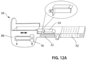
- the adjusting apparatus 24 may be a narrow long L-shape plate to change the width dimension of the carrying holder 30.
- the adjusting apparatus 24 may be disposed below the baffle apparatus 32, and in FIG.12C , part of the adjusting apparatus 24 may be made of the elastic and flexible material such as the soft plastic, rubber etc., and in FIG. 12D , the adjusting apparatus may merge with the baffle apparatus together.
- the control button 56 may be configured on the bottom of carrying holder 30 or the like, etc.
- the baffle apparatus 32 may be configured in an extending and retracting configuration between long and short configurations, to ensure that the gap created by movement of the carrying holder 30 is covered.
- part or all of the baffle apparatus 32 may be formed of the elastic and flexible material, such as soft plastic, rubber, nature or synthetic material etc. and when an external force actuates the delivering structure 10 to move from the stowed configuration to the dispensing configuration, the elastic part of the baffle apparatus 32 may extend, i.e., by stretching or expanding, for covering the gap caused by motion of the carrying holder 30, and when the external force is removed or canceled the elastic part of the baffle apparatus 32 may contract to facilitate the delivering structure 10 retreat back from the dispensing configuration to the stowed configuration.
- FIGS. 8-13B illustrate a baffle apparatus 32 configured in this manner. Because this embodiment may reduce the length of the baffle apparatus 32 or the length of the delivering structure 10 and enlarge the storage chamber 55 space for carrying more tablets and pills. It is within the teaching of the present disclosure that the baffle apparatus 32 may be formed of any suitable configurations and manners for the above intended functionality (i.e., extending and retracting), which permits shortening the length of the delivering structure 10 and enlarging the size of the storage chamber 55. In another embodiment, the baffle apparatus 32 may extend and retract by rolling.
- the baffle apparatus 32 in the stowed configuration may be disposed of a roll up configuration, like a self-retracting measure tape, with one distal tip connected to the carrying holder 30, and another distal tip may be connected directly or indirectly to the housing 8 (such as a rolling dispenser), with the tape rolled up, and a barrier apparatus 66 may be adjacent to the rolled up tape.
- the baffle apparatus 32 may stretch for covering the gap formed when the carrying holder 30 moves to dispensing position, and when the external force is cancel or removed the baffle apparatus 32 may roll up and facilitate the carrying holder 30 retreats back to the stowed position.
- the baffle apparatus 32 may be configured to extend and retract by folding, e.g., like an accordion door ( FIGS. 15A & B ), where one distal tip may connect to the holder 30, and another tip may be connected directly or indirectly to the housing 8.
- the baffle apparatus 32 folds together in the stowed position, and when an external force actuates the delivering structure 10 to move from the stowed configuration to the dispensing configuration, the baffle apparatus 32 may extend by unfolding for covering the gap formed when the carrying holder 30 moves to dispensing position, when the external force is removed the baffle apparatus 32 may contract or fold and facilitate the carrying holder 30 retreats back from the dispensing configuration to the stowed configuration.
- the baffle apparatus 32 may extend and retract by sliding.
- the baffle apparatus 32 in the stowed configuration the baffle apparatus 32 may be configured to expand by a sliding configuration, e.g., two or more sliding parts that slide with respect to each other, and the two or more parts of the baffle apparatus 32 may pile up together in the stowed configuration.
- One distal tip connects the holder 30 and another tip is directly or indirectly connected to the housing 8, and a barrier apparatus 66 may follow, and when an external force engages the delivering structure 10 to move from the stowed configuration to the dispensing configuration, the baffle apparatus 32 may slide and stretch for covering the gap formed when the carrying holder 30 moves to dispensing position.
- a biasing mechanism such as a spring 70 and spring hook 72 may be needed (see FIG. 17 ), when the external force is moved, the spring 70 may facilitate the delivering structure 10 automatically retreat back to the stowed configuration, or the like, etc. It is understood that the biasing mechanism (e.g., spring 70) in FIG. 17 may be used with other embodiments described herein.
- a thin layer of lower durometer hardness material may be coated or sprayed on the inside walls of the dispenser container (see FIG. 19 ).
- a second lid 76 of the dispenser may be disposed on the housing 8, open the lid the consumer may directly engage the button 56 of the adjusting apparatus 24.
- dispensing apparatuses have been described herein, which include various components and features. In other embodiments, the dispensing apparatus may be provided with any combination of such components and features. It is also understood that in other embodiments, the various devices, components, and features of the dispensing apparatus described herein may be constructed with similar structural and functional elements having different configurations, including different ornamental appearances.
Landscapes
- Health & Medical Sciences (AREA)
- Veterinary Medicine (AREA)
- Mechanical Engineering (AREA)
- Engineering & Computer Science (AREA)
- Life Sciences & Earth Sciences (AREA)
- Animal Behavior & Ethology (AREA)
- General Health & Medical Sciences (AREA)
- Public Health (AREA)
- Pharmacology & Pharmacy (AREA)
- Medical Preparation Storing Or Oral Administration Devices (AREA)
- Vending Machines For Individual Products (AREA)
- Closures For Containers (AREA)
- Confectionery (AREA)
- Packages (AREA)
Applications Claiming Priority (3)
| Application Number | Priority Date | Filing Date | Title |
|---|---|---|---|
| US201962830220P | 2019-04-05 | 2019-04-05 | |
| EP20784712.0A EP3947198B1 (en) | 2019-04-05 | 2020-04-06 | Dispensing apparatus |
| PCT/US2020/026833 WO2020206412A1 (en) | 2019-04-05 | 2020-04-06 | Dispensing apparatus |
Related Parent Applications (1)
| Application Number | Title | Priority Date | Filing Date |
|---|---|---|---|
| EP20784712.0A Division EP3947198B1 (en) | 2019-04-05 | 2020-04-06 | Dispensing apparatus |
Publications (1)
| Publication Number | Publication Date |
|---|---|
| EP4512742A1 true EP4512742A1 (en) | 2025-02-26 |
Family
ID=72667011
Family Applications (2)
| Application Number | Title | Priority Date | Filing Date |
|---|---|---|---|
| EP24184060.2A Pending EP4512742A1 (en) | 2019-04-05 | 2020-04-06 | Dispensing apparatus |
| EP20784712.0A Active EP3947198B1 (en) | 2019-04-05 | 2020-04-06 | Dispensing apparatus |
Family Applications After (1)
| Application Number | Title | Priority Date | Filing Date |
|---|---|---|---|
| EP20784712.0A Active EP3947198B1 (en) | 2019-04-05 | 2020-04-06 | Dispensing apparatus |
Country Status (9)
| Country | Link |
|---|---|
| US (1) | US12612236B2 (https=) |
| EP (2) | EP4512742A1 (https=) |
| JP (1) | JP2022527028A (https=) |
| KR (1) | KR20210148319A (https=) |
| CN (1) | CN113924258A (https=) |
| AU (1) | AU2020256275A1 (https=) |
| MX (1) | MX2021012241A (https=) |
| PH (1) | PH12021552778A1 (https=) |
| WO (1) | WO2020206412A1 (https=) |
Families Citing this family (1)
| Publication number | Priority date | Publication date | Assignee | Title |
|---|---|---|---|---|
| US12036185B2 (en) | 2021-07-19 | 2024-07-16 | Optum, Inc. | System and method to count pills |
Citations (1)
| Publication number | Priority date | Publication date | Assignee | Title |
|---|---|---|---|---|
| US20190092557A1 (en) * | 2017-09-22 | 2019-03-28 | Gumfriend International Corporation | Dispensing Container |
Family Cites Families (10)
| Publication number | Priority date | Publication date | Assignee | Title |
|---|---|---|---|---|
| US2669349A (en) | 1952-03-03 | 1954-02-16 | Edward C Silver | Pocket dispenser |
| US5174471A (en) * | 1992-06-10 | 1992-12-29 | Miles Inc. | Child-proof tablet dispenser |
| EP1002745A1 (de) * | 1998-11-17 | 2000-05-24 | Sanaro S.A. | Federbelasteter Drücker und mit einem solchen Drücker ausgerüstete Tabletten-Spendereinrichtung |
| GB2358627A (en) * | 2000-01-28 | 2001-08-01 | Bon Bon Buddies Ltd | Dispenser for confectionery products |
| EP1326790B1 (en) * | 2000-10-13 | 2005-12-21 | Cadbury Schweppes Plc | Tablet dispenser for dispensing individual tablets |
| CN2848753Y (zh) * | 2005-10-03 | 2006-12-20 | 彭实 | 密封式固体粉末定量取用装置 |
| JP4778842B2 (ja) * | 2006-06-19 | 2011-09-21 | 花王株式会社 | 携帯ケース |
| US10351333B2 (en) * | 2012-09-01 | 2019-07-16 | Gumfriend International Corp. | Dispensing container |
| CN206827345U (zh) * | 2017-04-15 | 2018-01-02 | 周主华 | 一种护理用丸剂药物存取器 |
| CN108438548A (zh) * | 2018-04-27 | 2018-08-24 | 张星星 | 定量容器及定量奶粉盒 |
-
2020
- 2020-04-06 PH PH1/2021/552778A patent/PH12021552778A1/en unknown
- 2020-04-06 JP JP2021560431A patent/JP2022527028A/ja active Pending
- 2020-04-06 CN CN202080041818.1A patent/CN113924258A/zh active Pending
- 2020-04-06 WO PCT/US2020/026833 patent/WO2020206412A1/en not_active Ceased
- 2020-04-06 KR KR1020217036154A patent/KR20210148319A/ko not_active Ceased
- 2020-04-06 MX MX2021012241A patent/MX2021012241A/es unknown
- 2020-04-06 US US17/598,875 patent/US12612236B2/en active Active
- 2020-04-06 EP EP24184060.2A patent/EP4512742A1/en active Pending
- 2020-04-06 EP EP20784712.0A patent/EP3947198B1/en active Active
- 2020-04-06 AU AU2020256275A patent/AU2020256275A1/en not_active Abandoned
Patent Citations (1)
| Publication number | Priority date | Publication date | Assignee | Title |
|---|---|---|---|---|
| US20190092557A1 (en) * | 2017-09-22 | 2019-03-28 | Gumfriend International Corporation | Dispensing Container |
Also Published As
| Publication number | Publication date |
|---|---|
| EP3947198B1 (en) | 2024-06-26 |
| WO2020206412A1 (en) | 2020-10-08 |
| KR20210148319A (ko) | 2021-12-07 |
| EP3947198C0 (en) | 2024-06-26 |
| JP2022527028A (ja) | 2022-05-27 |
| EP3947198A1 (en) | 2022-02-09 |
| US12612236B2 (en) | 2026-04-28 |
| EP3947198A4 (en) | 2023-05-24 |
| CN113924258A (zh) | 2022-01-11 |
| PH12021552778A1 (en) | 2022-09-19 |
| AU2020256275A1 (en) | 2021-12-02 |
| MX2021012241A (es) | 2022-01-24 |
| BR112021019617A2 (pt) | 2021-11-30 |
| US20240025627A1 (en) | 2024-01-25 |
Similar Documents
| Publication | Publication Date | Title |
|---|---|---|
| US12475755B2 (en) | Product dispensing system and methods | |
| US10889426B2 (en) | Dispensing container | |
| US10307023B2 (en) | Side-to-side tissue dispenser door restriction mechanism | |
| US9526383B2 (en) | Secondary dispenser method and apparatus | |
| EP3947198B1 (en) | Dispensing apparatus | |
| US20090008286A1 (en) | Dispenser with a Spout | |
| US20040130245A1 (en) | Bathroom items dispenser | |
| HK40066672A (zh) | 分配装置 | |
| WO2004024593A1 (en) | Dispenser for thin sheets | |
| US20250104502A1 (en) | Feminine product dispensing system and associated method | |
| WO2008068739A2 (en) | A compact tampon dispenser | |
| BR112021019617B1 (pt) | Aparelho de dispensação | |
| HK40032569A (en) | Dispensing apparatus | |
| KR20250149667A (ko) | 비누 스트립 디스펜서 | |
| HK40032569B (en) | Dispensing apparatus | |
| KR20250130677A (ko) | 비누 스트립, 디스펜서 및 리필 제품 |
Legal Events
| Date | Code | Title | Description |
|---|---|---|---|
| PUAI | Public reference made under article 153(3) epc to a published international application that has entered the european phase |
Free format text: ORIGINAL CODE: 0009012 |
|
| STAA | Information on the status of an ep patent application or granted ep patent |
Free format text: STATUS: THE APPLICATION HAS BEEN PUBLISHED |
|
| AC | Divisional application: reference to earlier application |
Ref document number: 3947198 Country of ref document: EP Kind code of ref document: P |
|
| AK | Designated contracting states |
Kind code of ref document: A1 Designated state(s): AL AT BE BG CH CY CZ DE DK EE ES FI FR GB GR HR HU IE IS IT LI LT LU LV MC MK MT NL NO PL PT RO RS SE SI SK SM TR |
|
| STAA | Information on the status of an ep patent application or granted ep patent |
Free format text: STATUS: REQUEST FOR EXAMINATION WAS MADE |
|
| 17P | Request for examination filed |
Effective date: 20250826 |
|
| GRAP | Despatch of communication of intention to grant a patent |
Free format text: ORIGINAL CODE: EPIDOSNIGR1 |
|
| STAA | Information on the status of an ep patent application or granted ep patent |
Free format text: STATUS: GRANT OF PATENT IS INTENDED |
|
| INTG | Intention to grant announced |
Effective date: 20251212 |
|
| GRAS | Grant fee paid |
Free format text: ORIGINAL CODE: EPIDOSNIGR3 |
|
| GRAA | (expected) grant |
Free format text: ORIGINAL CODE: 0009210 |
|
| STAA | Information on the status of an ep patent application or granted ep patent |
Free format text: STATUS: THE PATENT HAS BEEN GRANTED |