EP4512645A1 - Electric work vehicle - Google Patents
Electric work vehicle Download PDFInfo
- Publication number
- EP4512645A1 EP4512645A1 EP24184834.0A EP24184834A EP4512645A1 EP 4512645 A1 EP4512645 A1 EP 4512645A1 EP 24184834 A EP24184834 A EP 24184834A EP 4512645 A1 EP4512645 A1 EP 4512645A1
- Authority
- EP
- European Patent Office
- Prior art keywords
- connector section
- hood
- face portion
- charger
- side face
- Prior art date
- Legal status (The legal status is an assumption and is not a legal conclusion. Google has not performed a legal analysis and makes no representation as to the accuracy of the status listed.)
- Pending
Links
- 230000005540 biological transmission Effects 0.000 description 25
- 239000000428 dust Substances 0.000 description 4
- XLYOFNOQVPJJNP-UHFFFAOYSA-N water Substances O XLYOFNOQVPJJNP-UHFFFAOYSA-N 0.000 description 3
- 238000004519 manufacturing process Methods 0.000 description 2
- 244000025254 Cannabis sativa Species 0.000 description 1
- 239000010720 hydraulic oil Substances 0.000 description 1
- 229920003002 synthetic resin Polymers 0.000 description 1
- 239000000057 synthetic resin Substances 0.000 description 1
- 238000004078 waterproofing Methods 0.000 description 1
Images



Classifications
-
- B—PERFORMING OPERATIONS; TRANSPORTING
- B60—VEHICLES IN GENERAL
- B60K—ARRANGEMENT OR MOUNTING OF PROPULSION UNITS OR OF TRANSMISSIONS IN VEHICLES; ARRANGEMENT OR MOUNTING OF PLURAL DIVERSE PRIME-MOVERS IN VEHICLES; AUXILIARY DRIVES FOR VEHICLES; INSTRUMENTATION OR DASHBOARDS FOR VEHICLES; ARRANGEMENTS IN CONNECTION WITH COOLING, AIR INTAKE, GAS EXHAUST OR FUEL SUPPLY OF PROPULSION UNITS IN VEHICLES
- B60K1/00—Arrangement or mounting of electrical propulsion units
-
- B—PERFORMING OPERATIONS; TRANSPORTING
- B60—VEHICLES IN GENERAL
- B60L—PROPULSION OF ELECTRICALLY-PROPELLED VEHICLES; SUPPLYING ELECTRIC POWER FOR AUXILIARY EQUIPMENT OF ELECTRICALLY-PROPELLED VEHICLES; ELECTRODYNAMIC BRAKE SYSTEMS FOR VEHICLES IN GENERAL; MAGNETIC SUSPENSION OR LEVITATION FOR VEHICLES; MONITORING OPERATING VARIABLES OF ELECTRICALLY-PROPELLED VEHICLES; ELECTRIC SAFETY DEVICES FOR ELECTRICALLY-PROPELLED VEHICLES
- B60L53/00—Methods of charging batteries, specially adapted for electric vehicles; Charging stations or on-board charging equipment therefor; Exchange of energy storage elements in electric vehicles
- B60L53/10—Methods of charging batteries, specially adapted for electric vehicles; Charging stations or on-board charging equipment therefor; Exchange of energy storage elements in electric vehicles characterised by the energy transfer between the charging station and the vehicle
- B60L53/14—Conductive energy transfer
- B60L53/16—Connectors, e.g. plugs or sockets, specially adapted for charging electric vehicles
-
- B—PERFORMING OPERATIONS; TRANSPORTING
- B60—VEHICLES IN GENERAL
- B60K—ARRANGEMENT OR MOUNTING OF PROPULSION UNITS OR OF TRANSMISSIONS IN VEHICLES; ARRANGEMENT OR MOUNTING OF PLURAL DIVERSE PRIME-MOVERS IN VEHICLES; AUXILIARY DRIVES FOR VEHICLES; INSTRUMENTATION OR DASHBOARDS FOR VEHICLES; ARRANGEMENTS IN CONNECTION WITH COOLING, AIR INTAKE, GAS EXHAUST OR FUEL SUPPLY OF PROPULSION UNITS IN VEHICLES
- B60K15/00—Arrangement in connection with fuel supply of combustion engines or other fuel consuming energy converters, e.g. fuel cells; Mounting or construction of fuel tanks
- B60K15/03—Fuel tanks
- B60K15/04—Tank inlets
- B60K15/05—Inlet covers
-
- B—PERFORMING OPERATIONS; TRANSPORTING
- B60—VEHICLES IN GENERAL
- B60L—PROPULSION OF ELECTRICALLY-PROPELLED VEHICLES; SUPPLYING ELECTRIC POWER FOR AUXILIARY EQUIPMENT OF ELECTRICALLY-PROPELLED VEHICLES; ELECTRODYNAMIC BRAKE SYSTEMS FOR VEHICLES IN GENERAL; MAGNETIC SUSPENSION OR LEVITATION FOR VEHICLES; MONITORING OPERATING VARIABLES OF ELECTRICALLY-PROPELLED VEHICLES; ELECTRIC SAFETY DEVICES FOR ELECTRICALLY-PROPELLED VEHICLES
- B60L50/00—Electric propulsion with power supplied within the vehicle
- B60L50/50—Electric propulsion with power supplied within the vehicle using propulsion power supplied by batteries or fuel cells
- B60L50/60—Electric propulsion with power supplied within the vehicle using propulsion power supplied by batteries or fuel cells using power supplied by batteries
- B60L50/66—Arrangements of batteries
-
- B—PERFORMING OPERATIONS; TRANSPORTING
- B60—VEHICLES IN GENERAL
- B60K—ARRANGEMENT OR MOUNTING OF PROPULSION UNITS OR OF TRANSMISSIONS IN VEHICLES; ARRANGEMENT OR MOUNTING OF PLURAL DIVERSE PRIME-MOVERS IN VEHICLES; AUXILIARY DRIVES FOR VEHICLES; INSTRUMENTATION OR DASHBOARDS FOR VEHICLES; ARRANGEMENTS IN CONNECTION WITH COOLING, AIR INTAKE, GAS EXHAUST OR FUEL SUPPLY OF PROPULSION UNITS IN VEHICLES
- B60K1/00—Arrangement or mounting of electrical propulsion units
- B60K2001/001—Arrangement or mounting of electrical propulsion units one motor mounted on a propulsion axle for rotating right and left wheels of this axle
-
- B—PERFORMING OPERATIONS; TRANSPORTING
- B60—VEHICLES IN GENERAL
- B60K—ARRANGEMENT OR MOUNTING OF PROPULSION UNITS OR OF TRANSMISSIONS IN VEHICLES; ARRANGEMENT OR MOUNTING OF PLURAL DIVERSE PRIME-MOVERS IN VEHICLES; AUXILIARY DRIVES FOR VEHICLES; INSTRUMENTATION OR DASHBOARDS FOR VEHICLES; ARRANGEMENTS IN CONNECTION WITH COOLING, AIR INTAKE, GAS EXHAUST OR FUEL SUPPLY OF PROPULSION UNITS IN VEHICLES
- B60K1/00—Arrangement or mounting of electrical propulsion units
- B60K1/04—Arrangement or mounting of electrical propulsion units of the electric storage means for propulsion
- B60K2001/0405—Arrangement or mounting of electrical propulsion units of the electric storage means for propulsion characterised by their position
- B60K2001/0411—Arrangement in the front part of the vehicle
-
- B—PERFORMING OPERATIONS; TRANSPORTING
- B60—VEHICLES IN GENERAL
- B60K—ARRANGEMENT OR MOUNTING OF PROPULSION UNITS OR OF TRANSMISSIONS IN VEHICLES; ARRANGEMENT OR MOUNTING OF PLURAL DIVERSE PRIME-MOVERS IN VEHICLES; AUXILIARY DRIVES FOR VEHICLES; INSTRUMENTATION OR DASHBOARDS FOR VEHICLES; ARRANGEMENTS IN CONNECTION WITH COOLING, AIR INTAKE, GAS EXHAUST OR FUEL SUPPLY OF PROPULSION UNITS IN VEHICLES
- B60K15/00—Arrangement in connection with fuel supply of combustion engines or other fuel consuming energy converters, e.g. fuel cells; Mounting or construction of fuel tanks
- B60K15/03—Fuel tanks
- B60K15/04—Tank inlets
- B60K15/05—Inlet covers
- B60K2015/0515—Arrangements for closing or opening of inlet cover
- B60K2015/053—Arrangements for closing or opening of inlet cover with hinged connection to the vehicle body
-
- B—PERFORMING OPERATIONS; TRANSPORTING
- B60—VEHICLES IN GENERAL
- B60L—PROPULSION OF ELECTRICALLY-PROPELLED VEHICLES; SUPPLYING ELECTRIC POWER FOR AUXILIARY EQUIPMENT OF ELECTRICALLY-PROPELLED VEHICLES; ELECTRODYNAMIC BRAKE SYSTEMS FOR VEHICLES IN GENERAL; MAGNETIC SUSPENSION OR LEVITATION FOR VEHICLES; MONITORING OPERATING VARIABLES OF ELECTRICALLY-PROPELLED VEHICLES; ELECTRIC SAFETY DEVICES FOR ELECTRICALLY-PROPELLED VEHICLES
- B60L2200/00—Type of vehicles
- B60L2200/40—Working vehicles
-
- B—PERFORMING OPERATIONS; TRANSPORTING
- B60—VEHICLES IN GENERAL
- B60Y—INDEXING SCHEME RELATING TO ASPECTS CROSS-CUTTING VEHICLE TECHNOLOGY
- B60Y2200/00—Type of vehicle
- B60Y2200/20—Off-Road Vehicles
- B60Y2200/22—Agricultural vehicles
- B60Y2200/221—Tractors
-
- Y—GENERAL TAGGING OF NEW TECHNOLOGICAL DEVELOPMENTS; GENERAL TAGGING OF CROSS-SECTIONAL TECHNOLOGIES SPANNING OVER SEVERAL SECTIONS OF THE IPC; TECHNICAL SUBJECTS COVERED BY FORMER USPC CROSS-REFERENCE ART COLLECTIONS [XRACs] AND DIGESTS
- Y02—TECHNOLOGIES OR APPLICATIONS FOR MITIGATION OR ADAPTATION AGAINST CLIMATE CHANGE
- Y02T—CLIMATE CHANGE MITIGATION TECHNOLOGIES RELATED TO TRANSPORTATION
- Y02T10/00—Road transport of goods or passengers
- Y02T10/60—Other road transportation technologies with climate change mitigation effect
- Y02T10/70—Energy storage systems for electromobility, e.g. batteries
-
- Y—GENERAL TAGGING OF NEW TECHNOLOGICAL DEVELOPMENTS; GENERAL TAGGING OF CROSS-SECTIONAL TECHNOLOGIES SPANNING OVER SEVERAL SECTIONS OF THE IPC; TECHNICAL SUBJECTS COVERED BY FORMER USPC CROSS-REFERENCE ART COLLECTIONS [XRACs] AND DIGESTS
- Y02—TECHNOLOGIES OR APPLICATIONS FOR MITIGATION OR ADAPTATION AGAINST CLIMATE CHANGE
- Y02T—CLIMATE CHANGE MITIGATION TECHNOLOGIES RELATED TO TRANSPORTATION
- Y02T10/00—Road transport of goods or passengers
- Y02T10/60—Other road transportation technologies with climate change mitigation effect
- Y02T10/7072—Electromobility specific charging systems or methods for batteries, ultracapacitors, supercapacitors or double-layer capacitors
Definitions
- the present invention relates to a configuration relating to charging of a battery in an electric work vehicle.
- a hood is often provided in a front portion of a body, and a driving section is often provided behind the hood.
- a connector section to which a charger of an external power source (a charger included in an external power source facility) is connected to charge a battery may be provided on a lateral side of a steering wheel in the driving section as disclosed in Patent Document 1.
- Patent Document 1 JP 2022-60665A
- a work device such as a front loader is attached to the body of an electric tractor to perform work.
- portions of the work device such as a front loader may be located on the right side and the left side of the driving section.
- portions of a work device are located on the right side and the left side of the driving section in the electric tractor disclosed in Patent Document 1, it may be difficult to connect the charger of the external power source to the connector section due to the work device, and therefore, there is still room for improvement.
- An electric work vehicle includes: a body provided with a travel device; a battery; a motor configured to operate with power supplied from the battery and supply motive power to the travel device; a hood in a front portion of the body; a driving section behind the hood; and a connector section to which a charger is connected to charge the battery, wherein the connector section is in a front portion of the hood.
- the connector section is disposed in the front portion of the hood, and therefore, a worker can connect the charger to the connector section to charge the battery while standing in front of the body. Therefore, even if portions of a work device attached to the body are located on the right side and the left side of the driving section, the worker can easily connect the charger to the connector section without being affected by the work device. Consequently, workability of charging work can be improved.
- the battery is within the hood.
- the connector section is disposed in the front portion of the hood and the battery is disposed within the hood, and therefore, the connector section is close to the battery.
- the hood includes a top portion, a front face portion, a right side face portion, and a left side face portion, a right headlight and a left headlight are provided in a right region and a left region of an upper portion of the front face portion, respectively, and the connector section is disposed between the right headlight and the left headlight and oriented in such a manner that the charger is connected along a front-rear direction.
- an electric work vehicle includes a hood that includes a top portion, a front face portion, a right side face portion, and a left side face portion
- a right headlight and a left headlight may be provided in a right region and a left region of an upper portion of the front face portion of the hood.
- the connector section is disposed between the right headlight and the left headlight in this configuration and oriented in such a manner that the charger is connected in such a manner as to extend along the front-rear direction. Therefore, the worker can easily connect the charger to the connector section while standing in front of the body, and this configuration is advantageous in improving workability of the charging work.
- the connector section is within the hood and the front face portion includes a cover portion at a position corresponding to the connector section, the cover portion being openable and closable and configured to allow the charger to be connected to the connector section.
- the connector section is disposed within the hood and covered by the hood and the cover portion, and therefore, it is possible to suppress intrusion of rain water into the connector section and attachment of dust to the connector section, for example, and accordingly, it is possible to suppress damage to the connector section.
- the hood includes a top portion, a front face portion, a right side face portion, and a left side face portion, and the connector section is disposed in a front portion of the top portion and oriented in such a manner that the charger is connected along a front-rear direction or an up-down direction.
- the hood includes the top portion, the front face portion, the right side face portion, and the left side face portion, and the connector section is disposed in the front portion of the top portion of the hood.
- the connector section is oriented in such a manner that the charger is connected in such a manner as to extend along the front-rear direction or the up-down direction. Therefore, the worker can easily connect the charger to the connector section while standing in front of the body, and this configuration is advantageous in improving workability of the charging work.
- the connector section is within the hood and the top portion includes a cover portion at a position corresponding to the connector section, the cover portion being openable and closable and configured to allow the charger to be connected to the connector section.
- the connector section is disposed within the hood and covered by the hood and the cover portion, and therefore, it is possible to suppress intrusion of rain water into the connector section and attachment of dust to the connector section, for example, and accordingly, it is possible to suppress damage to the connector section.
- the hood includes a top portion, a front face portion, a right side face portion, and a left side face portion, and the connector section is disposed in a lower region of a front portion of the right side face portion or a lower region of a front portion of the left side face portion and oriented in such a manner that the charger is connected along a left-right direction.
- the hood includes the top portion, the front face portion, the right side face portion, and the left side face portion, and the connector section is disposed in the lower region of the front portion of the right side face portion (or the left side face portion) of the hood and oriented in such a manner that the charger is connected in such a manner as to extend along the left-right direction. Therefore, the worker can easily connect the charger to the connector section while standing in front of the body, and this configuration is advantageous in improving workability of the charging work.
- electric work vehicles may be produced by installing a battery and a motor on the body
- engine work vehicles may be produced by installing an engine on the body.
- an exhaust port of an exhaust pipe extending from the engine may be disposed in the lower region of the front portion of the right side face portion (or the left side face portion) of the hood.
- the lower region of the front portion of the right side face portion (or the left side face portion) of the hood can be used as a region for disposing the connector section as well as a region for disposing the exhaust port of the exhaust pipe, and therefore, it is possible to simplify the structure.
- the connector section is within the hood and the right side face portion or the left side face portion includes a cover portion at a position corresponding to the connector section, the cover portion being openable and closable and configured to allow the charger to be connected to the connector section.
- the connector section is disposed within the hood and covered by the hood and the cover portion, and therefore, it is possible to suppress intrusion of rain water into the connector section and attachment of dust to the connector section, for example, and accordingly, it is possible to suppress damage to the connector section.
- FIGS. 1 to 8 show a tractor, which is an example of an electric work vehicle.
- F indicates the front side
- B indicates the rear side
- U indicates the upper side
- D indicates the lower side
- R indicates the right side
- L indicates the left side.
- right and left front wheels 1 (corresponding to travel devices) and right and left rear wheels 2 (corresponding to travel devices) are attached to a body 3.
- a hood 4 is provided in a front portion of the body 3, and a driving section 5 is provided in a rear portion of the body 3.
- the driving section 5 includes a steering wheel 6 for changing orientations of the front wheels 1, a driver's seat 7, and a ROPS frame 9.
- the body 3 includes right and left body frames 10, a continuously variable transmission 11, a transmission case 12, etc.
- the continuously variable transmission 11 is coupled to a front portion of the transmission case 12.
- the body frames 10 are coupled to the continuously variable transmission 11 and the transmission case 12 and extend along the front-rear direction.
- a front wheel shaft case 8 is attached to front portions of the body frames 10.
- the front wheels 1 are attached to the front wheel shaft case 8.
- the rear wheels 2 are attached to the transmission case 12.
- a single top link 13 and right and left lower links 14 are attached to a rear portion of the transmission case 12 in such a manner as to be swingable in the up-down direction.
- Right and left lift arms 15 are provided on the rear portion of the transmission case 12.
- Rods 16 are connected to the lift arms 15 and the lower links 14.
- Various work devices can be attached to the top link 13 and the lower links 14.
- a work device is lifted and lowered via the top link 13 and the lower links 14 by operating the lift arms 15 so as to swing in the up-down direction.
- a front loader 17 is attached to the front portion of the body 3.
- the front loader 17 includes base portions 18, booms 19, a bucket 20, boom cylinders 21, a bucket cylinder 22, a frame 23, etc.
- the right and left base portions 18 are coupled to the body frames 10 and extend upward on the right side and the left side of a rear portion of the hood 4.
- the right and left booms 19 are attached to respective upper portions of the base portions 18 in such a manner as to be swingable in the up-down direction and extend forward.
- the right and left boom cylinders 21 are attached to the base portions 18 and the booms 19. The booms 19 are lifted and lowered by the boom cylinders 21.
- the bucket 20 is attached to front portions of the booms 19 in such a manner as to be swingable in the up-down direction.
- the frame 23 is coupled to the right and left booms 19.
- the bucket cylinder 22 is connected to the bucket 20 and the frame 23.
- the bucket 20 is caused to perform a scooping operation and a dumping operation by the bucket cylinder 22.
- a mower 24 is attached to the body frames 10 in such a manner as to be capable of being lifted and lowered and is disposed between the front wheels 1 and the rear wheels 2.
- the mower 24 includes three blades (not shown) disposed side by side in the left-right direction within the mower 24, and each blade is driven to rotate about an axis extending in the up-down direction. Grass reaped by the blades is discharged rightward from a discharge section 24a on the right side of the mower 24.
- a battery 27, an inverter 28, a motor 29, a battery 33, etc., are provided on the front portions of the body frames 10.
- Right and left support members 25 are coupled to the front portions of the body frames 10.
- a flat plate-shaped support frame 26 is coupled to the support members 25.
- the battery 27 is attached to an upper surface portion of the support frame 26. The battery 27 is disposed within the hood 4.
- the inverter 28 is attached to a front region of a lower surface portion of the support frame 26.
- the motor 29 is attached to a rear region of the lower surface portion of the support frame 26 and disposed between the right and left body frames 10.
- the inverter 28 and the motor 29 are covered by a lower cover 30 from below.
- Fans 31 are attached to a front portion of the lower cover 30. Outside air is introduced into the inside of the lower cover 30 by the fans 31 to cool the inverter 28 and the motor 29 with the outside air.
- An arch-shaped frame 32 is coupled to the right and left body frames 10 at a position corresponding to a rear end portion of the hood 4.
- the battery 33 which outputs 12 V power, is attached to the frame 32.
- Power is supplied from the battery 27 to the inverter 28, the DC power supplied from the battery 27 is converted to AC power in the inverter 28, and the AC power is supplied to the motor 29 to cause the motor 29 to operate.
- Power is supplied from the battery 27 to a DC-DC converter (not shown), and the voltage of the supplied power is reduced to 12 V in the DC-DC converter.
- the power with the reduced voltage of 12 V is supplied to the battery 33.
- Various devices (not shown) installed in the tractor operate with the 12 V power supplied from the battery 33.
- the continuously variable transmission 11 is a hydraulic transmission and capable of changing the speed of the motive power in a stepless manner in a forward traveling direction and a rearward traveling direction.
- Motive power subjected to the speed change in the continuously variable transmission 11 is transmitted via an auxiliary transmission (not shown) and a rear wheel differential device (not shown) provided within the transmission case 12 to the rear wheels 2.
- Motive power diverging from a position right before the rear wheel differential device is transmitted via transmission shafts 35 and 36 to a front wheel differential device (not shown) provided within the front wheel shaft case 8, and transmitted from the front wheel differential device to the front wheels 1.
- a PTO shaft 37 is provided in a lower region of the front portion of the transmission case 12 in such a manner as to face forward.
- a PTO shaft 38 is provided on the rear portion of the transmission case 12 in such a manner as to face rearward.
- Motive power that is transmitted by the transmission shaft 34 and not subjected to the speed change in the continuously variable transmission 11 is transmitted to the PTO shafts 37 and 38, and a hydraulic pump (not shown) is driven by the motive power not subjected to the speed change in the continuously variable transmission 11.
- Motive power is transmitted from the PTO shaft 37 via a transmission shaft (not shown) to the mower 24.
- Motive power is transmitted from the PTO shaft 38 via a transmission shaft (not shown) to the work device attached to the top link 13 and the lower links 14.
- the boom cylinders 21 and the bucket cylinder 22 included in the front loader 17 and a hydraulic cylinder (not shown) for swinging the lift arms 15 are operated with hydraulic oil supplied from the hydraulic pump.
- the tractor includes: the body 3 provided with the travel devices (the front wheels 1 and the rear wheels 2); and the battery 27.
- the tractor also includes the motor 29 configured to operate with power supplied from the battery 27 and supply motive power to the travel devices (the front wheels 1 and the rear wheels 2).
- the tractor also includes the hood 4 in the front portion of the body 3 and the driving section 5 behind the hood 4.
- the battery 27 is within the hood 4.
- the hood 4 includes a top portion 40, a front face portion 41, a right side face portion 42, and a left side face portion 43 that are formed as a single piece from a synthetic resin.
- the hood 4 is attached to the frame 32 in such a manner as to be swingable about an axis P1 extending in the left-right direction and capable of being operated to a closed position (see FIGS. 1 , 2 , and 3 ) and an open position spaced upward from the closed position.
- a front grill 46 including a large number of small openings is provided in a lower portion of the front face portion 41, a front portion of the right side face portion 42, and a front portion of the left side face portion 43 of the hood 4.
- the front grill 46 is a part of the front face portion 41 of the hood 4, a part of the right side face portion 42 of the hood 4, and a part of the left side face portion 43 of the hood 4.
- a right headlight 44 and a left headlight 45 are respectively provided in a right region and a left region of an upper portion of the front face portion 41 of the hood 4.
- Side grills 49 including a large number of small openings are provided in the right side face portion 42 and the left side face portion 43 of the hood 4.
- the front face portion 41 of the hood 4 includes an opening 47 between the right headlight 44 and the left headlight 45.
- a cover portion 48 is attached to the front face portion 41 of the hood 4 (an upper edge of the opening 47) in such a manner as to be swingable about an axis P2 extending in the left-right direction.
- the cover portion 48 can be operated to a closed position (see FIG. 1 ) and an open position (see FIGS. 2 and 3 ).
- right and left frames 50 that have an angular shape in a side view are coupled to front end portions of the body frames 10 and the frame 32 within the hood 4 and disposed above and in front of the battery 27.
- Right and left frames 51 extending in the up-down direction are coupled to a front portion of the support frame 26 and front regions of respective upper portions of the frames 50 within the hood 4 and disposed in front of the battery 27.
- a frame 52 extending in the left-right direction is coupled to the respective upper portions of the right and left frames 50 and disposed above the battery 27.
- a frame 53 extending in the left-right direction is coupled to upper regions of respective front portions of the right and left frames 50 within the hood 4.
- a connector section 39 is attached to a center portion of the frame 53 in the left-right direction.
- the connector section 39 faces forward behind the opening 47 of the front face portion 41 of the hood 4.
- the connector section 39 is exposed to the front side of the hood 4 via the opening 47 of the hood 4.
- a worker connects a charger (not shown) of an external power source (not shown) to the connector section 39 via the opening 47 of the hood 4 from the front side of the hood 4.
- the charger of the external power source is connected to the connector section 39 in such a manner as to extend along the front-rear direction, and the battery 27 is charged with power supplied from the external power source via the connector section 39.
- the tractor includes the connector section 39 to which a charger is connected to charge the battery 27, and the connector section 39 is disposed in a front portion of the hood 4.
- the hood 4 includes the top portion 40, the front face portion 41, the right side face portion 42, and the left side face portion 43.
- the right headlight 44 and the left headlight 45 are provided in the right region and the left region of the upper portion of the front face portion 41.
- the connector section 39 is disposed between the right headlight 44 and the left headlight 45 and oriented in such a manner that the charger is connected along the front-rear direction.
- the connector section 39 is within the hood 4.
- the front face portion 41 includes the cover portion 48 at a position corresponding to the connector section 39, and the cover portion 48 is openable and closable and allows the charger to be connected to the connector section 39.
- an opening 54 is provided in a center region in the left-right direction of a front portion of the top portion 40 of the hood 4.
- a cover portion 55 is attached to the front portion of the top portion 40 (a rear edge of the opening 54) of the hood 4 in such a manner as to be swingable about an axis P3 extending in the left-right direction.
- the cover portion 55 can be operated to a closed position and an open position (see FIG. 5 ).
- a frame 56 extending in the left-right direction is coupled to the front regions of the respective upper portions of the right and left frames 50 within the hood 4.
- the connector section 39 is attached to a center portion of the frame 56 in the left-right direction.
- the connector section 39 faces upward under the opening 54 of the hood 4. When the cover portion 55 is operated to the closed position, the connector section 39 is covered by the cover portion 55 and is not exposed to the upper side of the hood 4.
- the connector section 39 is exposed to the upper side of the hood 4 via the opening 54 of the hood 4.
- the worker connects the charger (not shown) of the external power source (not shown) to the connector section 39 via the opening 54 of the hood 4 from the upper side of the hood 4. Accordingly, the charger of the external power source is connected to the connector section 39 in such a manner as to extend along the up-down direction, and the battery 27 is charged with power supplied from the external power source via the connector section 39.
- the connector section 39 may also be attached to the frame 56 in such a manner as to face diagonally upward and forward. According to this configuration, the charger of the external power source is connected to the connector section 39 in such a manner as to extend in the front-rear direction via the opening 54 of the hood 4 from the upper side and the front side of the hood 4.
- the tractor includes the connector section 39 to which a charger is connected to charge the battery 27, and the connector section 39 is disposed in the front portion of the hood 4.
- the hood 4 includes the top portion 40, the front face portion 41, the right side face portion 42, and the left side face portion 43.
- the connector section 39 is disposed in the front portion of the top portion 40 and oriented in such a manner that the charger is connected along the front-rear direction or the up-down direction.
- the connector section 39 is within the hood 4.
- the top portion 40 includes the cover portion 55 at a position corresponding to the connector section 39, and the cover portion 55 is openable and closable and allows the charger to be connected to the connector section 39.
- an opening 57 is provided in the front portion of the left side face portion 43 (a lower region of a left portion of the front grill 46) of the hood 4.
- a cover portion 58 is attached to a lower region of the front portion of the left side face portion 43 (the lower region of the left portion of the front grill 46) (a rear edge of the opening 57) of the hood 4 in such a manner as to be swingable about an axis P4 extending in the up-down direction.
- the cover portion 58 can be operated to a closed position and an open position (see FIG. 8 ).
- a bracket 59 is coupled to a lower portion of the left frame 51 within the hood 4, and the connector section 39 is attached to the bracket 59.
- the connector section 39 faces leftward and is disposed on the right side of the opening 57 of the hood 4.
- the connector section 39 is covered by the cover portion 58 and is not exposed to the left side of the hood 4.
- the connector section 39 is exposed to the left side of the hood 4 via the opening 57 of the hood 4.
- the worker connects the charger (not shown) of the external power source (not shown) to the connector section 39 via the opening 57 of the hood 4 from the left side of the hood 4. Accordingly, the charger of the external power source is connected to the connector section 39 in such a manner as to extend along the left-right direction, and the battery 27 is charged with power supplied from the external power source via the connector section 39.
- the connector section 39 may also be attached to a lower portion of the right frame 51 in such manner as to face rightward, and the opening 57 and the cover portion 58 may also be provided in a lower region of the front portion of the right side face portion 42 (a lower region of a right portion of the front grill 46) of the hood 4.
- the tractor includes the connector section 39 to which a charger is connected to charge the battery 27, and the connector section 39 is disposed in the front portion of the hood 4.
- the hood 4 includes the top portion 40, the front face portion 41, the right side face portion 42, and the left side face portion 43.
- the connector section 39 is disposed in the lower region of the front portion of the right side face portion 42 or the lower region of the front portion of the left side face portion 43 and oriented in such a manner that the charger is connected along the left-right direction.
- the connector section 39 is within the hood 4.
- the right side face portion 42 or the left side face portion 43 includes the cover portion 58 at a position corresponding to the connector section 39, and the cover portion 58 is openable and closable and allows the charger to be connected to the connector section 39.
- An engine work vehicle may be produced by eliminating the battery 27, the inverter 28, the motor 29, etc., in the configuration shown in FIGS. 7 and 8 and installing an engine (not shown) on the front portions of the body frames 10.
- a configuration is also possible in which the connector section 39 is directly attached to the front portion of the hood 4, rather than being disposed within the hood 4. According to this configuration, the connector section 39 is exposed, and therefore, it is preferable to provide the connector section 39 with a cap (not shown) for dust proofing and water proofing, which is attachable to the connector section 39 and detachable therefrom.
- Crawler travel devices may also be used as travel devices instead of the rear wheels 2.
- Crawler travel devices may also be used as travel devices instead of the front wheels 1 and the rear wheels 2.
- the present invention is applicable to not only a tractor but also other electric work vehicles such as an electric cart and a transport vehicle.
Landscapes
- Engineering & Computer Science (AREA)
- Transportation (AREA)
- Mechanical Engineering (AREA)
- Power Engineering (AREA)
- Life Sciences & Earth Sciences (AREA)
- Sustainable Development (AREA)
- Sustainable Energy (AREA)
- Chemical & Material Sciences (AREA)
- Combustion & Propulsion (AREA)
- Arrangement Or Mounting Of Propulsion Units For Vehicles (AREA)
- Superstructure Of Vehicle (AREA)
Abstract
An electric work vehicle includes a hood (4) in a front portion of a body and a driving section (5) behind the hood (4). The electric work vehicle includes a connector section (39) to which a charger is connected to charge a battery, and the connector section (39) is in a front portion of the hood (4).
Description
- The present invention relates to a configuration relating to charging of a battery in an electric work vehicle.
- In an electric tractor, which is an example of an electric work vehicle, a hood is often provided in a front portion of a body, and a driving section is often provided behind the hood.
- In such an electric tractor, a connector section to which a charger of an external power source (a charger included in an external power source facility) is connected to charge a battery may be provided on a lateral side of a steering wheel in the driving section as disclosed in
Patent Document 1. - Patent Document 1:
JP 2022-60665A - In many cases, a work device such as a front loader is attached to the body of an electric tractor to perform work. In this case, portions of the work device such as a front loader may be located on the right side and the left side of the driving section.
- If portions of a work device are located on the right side and the left side of the driving section in the electric tractor disclosed in
Patent Document 1, it may be difficult to connect the charger of the external power source to the connector section due to the work device, and therefore, there is still room for improvement. - An object of the present invention is to configure an electric work vehicle in such a manner that a charger of an external power source can be easily connected to a connector section.
- An electric work vehicle according to an aspect of the present invention includes: a body provided with a travel device; a battery; a motor configured to operate with power supplied from the battery and supply motive power to the travel device; a hood in a front portion of the body; a driving section behind the hood; and a connector section to which a charger is connected to charge the battery, wherein the connector section is in a front portion of the hood.
- According to this aspect of the present invention, the connector section is disposed in the front portion of the hood, and therefore, a worker can connect the charger to the connector section to charge the battery while standing in front of the body. Therefore, even if portions of a work device attached to the body are located on the right side and the left side of the driving section, the worker can easily connect the charger to the connector section without being affected by the work device. Consequently, workability of charging work can be improved.
- In an aspect of the present invention, it is preferable that the battery is within the hood.
- According to this aspect of the present invention, the connector section is disposed in the front portion of the hood and the battery is disposed within the hood, and therefore, the connector section is close to the battery. With this configuration, it is possible to reduce the length of a harness or the like connecting the connector section and the battery, and accordingly, it is possible to simplify the structure.
- In an aspect of the present invention, it is preferable that the hood includes a top portion, a front face portion, a right side face portion, and a left side face portion, a right headlight and a left headlight are provided in a right region and a left region of an upper portion of the front face portion, respectively, and the connector section is disposed between the right headlight and the left headlight and oriented in such a manner that the charger is connected along a front-rear direction.
- If an electric work vehicle includes a hood that includes a top portion, a front face portion, a right side face portion, and a left side face portion, a right headlight and a left headlight may be provided in a right region and a left region of an upper portion of the front face portion of the hood.
- According to this aspect of the present invention, the connector section is disposed between the right headlight and the left headlight in this configuration and oriented in such a manner that the charger is connected in such a manner as to extend along the front-rear direction. Therefore, the worker can easily connect the charger to the connector section while standing in front of the body, and this configuration is advantageous in improving workability of the charging work.
- In an aspect of the present invention, it is preferable that the connector section is within the hood and the front face portion includes a cover portion at a position corresponding to the connector section, the cover portion being openable and closable and configured to allow the charger to be connected to the connector section.
- According to this aspect of the present invention, the connector section is disposed within the hood and covered by the hood and the cover portion, and therefore, it is possible to suppress intrusion of rain water into the connector section and attachment of dust to the connector section, for example, and accordingly, it is possible to suppress damage to the connector section.
- When the worker connects the charger to the connector section, the worker can connect the charger to the connector section without difficulty by opening the cover portion, and therefore, this configuration does not impair workability.
- In an aspect of the present invention, it is preferable that the hood includes a top portion, a front face portion, a right side face portion, and a left side face portion, and the connector section is disposed in a front portion of the top portion and oriented in such a manner that the charger is connected along a front-rear direction or an up-down direction.
- According to this aspect of the present invention, the hood includes the top portion, the front face portion, the right side face portion, and the left side face portion, and the connector section is disposed in the front portion of the top portion of the hood. Also, the connector section is oriented in such a manner that the charger is connected in such a manner as to extend along the front-rear direction or the up-down direction. Therefore, the worker can easily connect the charger to the connector section while standing in front of the body, and this configuration is advantageous in improving workability of the charging work.
- In an aspect of the present invention, it is preferable that the connector section is within the hood and the top portion includes a cover portion at a position corresponding to the connector section, the cover portion being openable and closable and configured to allow the charger to be connected to the connector section.
- According to this aspect of the present invention, the connector section is disposed within the hood and covered by the hood and the cover portion, and therefore, it is possible to suppress intrusion of rain water into the connector section and attachment of dust to the connector section, for example, and accordingly, it is possible to suppress damage to the connector section.
- When the worker connects the charger to the connector section, the worker can connect the charger to the connector section without difficulty by opening the cover portion, and therefore, this configuration does not impair workability.
- In an aspect of the present invention, it is preferable that the hood includes a top portion, a front face portion, a right side face portion, and a left side face portion, and the connector section is disposed in a lower region of a front portion of the right side face portion or a lower region of a front portion of the left side face portion and oriented in such a manner that the charger is connected along a left-right direction.
- According to this aspect of the present invention, the hood includes the top portion, the front face portion, the right side face portion, and the left side face portion, and the connector section is disposed in the lower region of the front portion of the right side face portion (or the left side face portion) of the hood and oriented in such a manner that the charger is connected in such a manner as to extend along the left-right direction. Therefore, the worker can easily connect the charger to the connector section while standing in front of the body, and this configuration is advantageous in improving workability of the charging work.
- In the production of work vehicles, electric work vehicles may be produced by installing a battery and a motor on the body, and engine work vehicles may be produced by installing an engine on the body. In the production of engine work vehicles, an exhaust port of an exhaust pipe extending from the engine may be disposed in the lower region of the front portion of the right side face portion (or the left side face portion) of the hood.
- According to this aspect of the present invention, the lower region of the front portion of the right side face portion (or the left side face portion) of the hood can be used as a region for disposing the connector section as well as a region for disposing the exhaust port of the exhaust pipe, and therefore, it is possible to simplify the structure.
- In an aspect of the present invention, it is preferable that the connector section is within the hood and the right side face portion or the left side face portion includes a cover portion at a position corresponding to the connector section, the cover portion being openable and closable and configured to allow the charger to be connected to the connector section.
- According to this aspect of the present invention, the connector section is disposed within the hood and covered by the hood and the cover portion, and therefore, it is possible to suppress intrusion of rain water into the connector section and attachment of dust to the connector section, for example, and accordingly, it is possible to suppress damage to the connector section.
- When the worker connects the charger to the connector section, the worker can connect the charger to the connector section without difficulty by opening the cover portion, and therefore, this configuration does not impair workability.
-
-
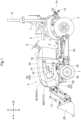
FIG. 1 is a left side view of a tractor. -
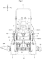
FIG. 2 is a front view of the tractor. -
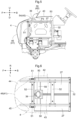
FIG. 3 is a longitudinal cross-sectional view showing arrangement of a connector section, a battery, a motor, etc., as viewed from the left side. -
FIG. 4 is a plan view showing the vicinity of the connector section and the battery. -
FIG. 5 is a longitudinal cross-sectional view showing the vicinity of the connector section and the battery as viewed from the left side in a first variation of the invention. -
FIG. 6 is a plan view showing the vicinity of the connector section and the battery in the first variation of the invention. -
FIG. 7 is a longitudinal cross-sectional view showing the vicinity of the connector section and the battery as viewed from the left side in a second variation of the invention. -
FIG. 8 is a plan view showing the vicinity of the connector section and the battery in the second variation of the invention. -
FIGS. 1 to 8 show a tractor, which is an example of an electric work vehicle. InFIGS. 1 to 8 , F indicates the front side, B indicates the rear side, U indicates the upper side, D indicates the lower side, R indicates the right side, and L indicates the left side. - As shown in
FIGS. 1 and2 , right and left front wheels 1 (corresponding to travel devices) and right and left rear wheels 2 (corresponding to travel devices) are attached to abody 3. Ahood 4 is provided in a front portion of thebody 3, and adriving section 5 is provided in a rear portion of thebody 3. Thedriving section 5 includes asteering wheel 6 for changing orientations of thefront wheels 1, a driver'sseat 7, and aROPS frame 9. - As shown in
FIGS. 1 and3 , thebody 3 includes right andleft body frames 10, a continuouslyvariable transmission 11, atransmission case 12, etc. The continuouslyvariable transmission 11 is coupled to a front portion of thetransmission case 12. Thebody frames 10 are coupled to the continuouslyvariable transmission 11 and thetransmission case 12 and extend along the front-rear direction. A frontwheel shaft case 8 is attached to front portions of thebody frames 10. Thefront wheels 1 are attached to the frontwheel shaft case 8. Therear wheels 2 are attached to thetransmission case 12. - A single
top link 13 and right and leftlower links 14 are attached to a rear portion of thetransmission case 12 in such a manner as to be swingable in the up-down direction. Right and left liftarms 15 are provided on the rear portion of thetransmission case 12.Rods 16 are connected to thelift arms 15 and thelower links 14. - Various work devices (not shown) can be attached to the
top link 13 and thelower links 14. A work device is lifted and lowered via thetop link 13 and thelower links 14 by operating thelift arms 15 so as to swing in the up-down direction. - As shown in
FIGS. 1 and2 , afront loader 17 is attached to the front portion of thebody 3. Thefront loader 17 includesbase portions 18,booms 19, abucket 20,boom cylinders 21, abucket cylinder 22, aframe 23, etc. - The right and left
base portions 18 are coupled to the body frames 10 and extend upward on the right side and the left side of a rear portion of thehood 4. The right and leftbooms 19 are attached to respective upper portions of thebase portions 18 in such a manner as to be swingable in the up-down direction and extend forward. The right and leftboom cylinders 21 are attached to thebase portions 18 and thebooms 19. Thebooms 19 are lifted and lowered by theboom cylinders 21. - The
bucket 20 is attached to front portions of thebooms 19 in such a manner as to be swingable in the up-down direction. Theframe 23 is coupled to the right and leftbooms 19. Thebucket cylinder 22 is connected to thebucket 20 and theframe 23. Thebucket 20 is caused to perform a scooping operation and a dumping operation by thebucket cylinder 22. - As shown in
FIGS. 1 and2 , amower 24 is attached to the body frames 10 in such a manner as to be capable of being lifted and lowered and is disposed between thefront wheels 1 and therear wheels 2. - The
mower 24 includes three blades (not shown) disposed side by side in the left-right direction within themower 24, and each blade is driven to rotate about an axis extending in the up-down direction. Grass reaped by the blades is discharged rightward from adischarge section 24a on the right side of themower 24. - As shown in
FIGS. 3 and4 , abattery 27, aninverter 28, amotor 29, abattery 33, etc., are provided on the front portions of the body frames 10. - Right and left support members 25 (see
FIG. 1 ) are coupled to the front portions of the body frames 10. A flat plate-shapedsupport frame 26 is coupled to thesupport members 25. Thebattery 27 is attached to an upper surface portion of thesupport frame 26. Thebattery 27 is disposed within thehood 4. - The
inverter 28 is attached to a front region of a lower surface portion of thesupport frame 26. Themotor 29 is attached to a rear region of the lower surface portion of thesupport frame 26 and disposed between the right and left body frames 10. - The
inverter 28 and themotor 29 are covered by alower cover 30 from below.Fans 31 are attached to a front portion of thelower cover 30. Outside air is introduced into the inside of thelower cover 30 by thefans 31 to cool theinverter 28 and themotor 29 with the outside air. - An arch-shaped
frame 32 is coupled to the right and left body frames 10 at a position corresponding to a rear end portion of thehood 4. Thebattery 33, which outputs 12 V power, is attached to theframe 32. - Power is supplied from the
battery 27 to theinverter 28, the DC power supplied from thebattery 27 is converted to AC power in theinverter 28, and the AC power is supplied to themotor 29 to cause themotor 29 to operate. - Power is supplied from the
battery 27 to a DC-DC converter (not shown), and the voltage of the supplied power is reduced to 12 V in the DC-DC converter. The power with the reduced voltage of 12 V is supplied to thebattery 33. Various devices (not shown) installed in the tractor operate with the 12 V power supplied from thebattery 33. - Configuration of transmission system for front wheels, rear wheels, and mower
- As shown in
FIG. 3 , motive power is transmitted from themotor 29 via atransmission shaft 34 to the continuouslyvariable transmission 11. The continuouslyvariable transmission 11 is a hydraulic transmission and capable of changing the speed of the motive power in a stepless manner in a forward traveling direction and a rearward traveling direction. - Motive power subjected to the speed change in the continuously
variable transmission 11 is transmitted via an auxiliary transmission (not shown) and a rear wheel differential device (not shown) provided within thetransmission case 12 to therear wheels 2. Motive power diverging from a position right before the rear wheel differential device is transmitted viatransmission shafts wheel shaft case 8, and transmitted from the front wheel differential device to thefront wheels 1. - A
PTO shaft 37 is provided in a lower region of the front portion of thetransmission case 12 in such a manner as to face forward. APTO shaft 38 is provided on the rear portion of thetransmission case 12 in such a manner as to face rearward. Motive power that is transmitted by thetransmission shaft 34 and not subjected to the speed change in the continuouslyvariable transmission 11 is transmitted to thePTO shafts variable transmission 11. - Motive power is transmitted from the
PTO shaft 37 via a transmission shaft (not shown) to themower 24. Motive power is transmitted from thePTO shaft 38 via a transmission shaft (not shown) to the work device attached to thetop link 13 and thelower links 14. Theboom cylinders 21 and thebucket cylinder 22 included in thefront loader 17 and a hydraulic cylinder (not shown) for swinging thelift arms 15 are operated with hydraulic oil supplied from the hydraulic pump. - According to the above configuration, the tractor includes: the
body 3 provided with the travel devices (thefront wheels 1 and the rear wheels 2); and thebattery 27. The tractor also includes themotor 29 configured to operate with power supplied from thebattery 27 and supply motive power to the travel devices (thefront wheels 1 and the rear wheels 2). - The tractor also includes the
hood 4 in the front portion of thebody 3 and thedriving section 5 behind thehood 4. Thebattery 27 is within thehood 4. - As shown in
FIGS. 1 to 4 , thehood 4 includes atop portion 40, afront face portion 41, a rightside face portion 42, and a leftside face portion 43 that are formed as a single piece from a synthetic resin. Thehood 4 is attached to theframe 32 in such a manner as to be swingable about an axis P1 extending in the left-right direction and capable of being operated to a closed position (seeFIGS. 1 ,2 , and3 ) and an open position spaced upward from the closed position. - A
front grill 46 including a large number of small openings is provided in a lower portion of thefront face portion 41, a front portion of the rightside face portion 42, and a front portion of the leftside face portion 43 of thehood 4. Thefront grill 46 is a part of thefront face portion 41 of thehood 4, a part of the rightside face portion 42 of thehood 4, and a part of the leftside face portion 43 of thehood 4. - A
right headlight 44 and aleft headlight 45 are respectively provided in a right region and a left region of an upper portion of thefront face portion 41 of thehood 4. Side grills 49 including a large number of small openings are provided in the rightside face portion 42 and the leftside face portion 43 of thehood 4. - The
front face portion 41 of thehood 4 includes anopening 47 between theright headlight 44 and theleft headlight 45. Acover portion 48 is attached to thefront face portion 41 of the hood 4 (an upper edge of the opening 47) in such a manner as to be swingable about an axis P2 extending in the left-right direction. Thecover portion 48 can be operated to a closed position (seeFIG. 1 ) and an open position (seeFIGS. 2 and3 ). - Configuration of connector section to which charger of external power source is connected to charge battery
- As shown in
FIGS. 3 and4 , right and leftframes 50 that have an angular shape in a side view are coupled to front end portions of the body frames 10 and theframe 32 within thehood 4 and disposed above and in front of thebattery 27. - Right and left
frames 51 extending in the up-down direction are coupled to a front portion of thesupport frame 26 and front regions of respective upper portions of theframes 50 within thehood 4 and disposed in front of thebattery 27. Aframe 52 extending in the left-right direction is coupled to the respective upper portions of the right and leftframes 50 and disposed above thebattery 27. - As shown in
FIGS. 2 ,3 , and4 , aframe 53 extending in the left-right direction is coupled to upper regions of respective front portions of the right and leftframes 50 within thehood 4. Aconnector section 39 is attached to a center portion of theframe 53 in the left-right direction. Theconnector section 39 faces forward behind theopening 47 of thefront face portion 41 of thehood 4. When thecover portion 48 is operated to the closed position (seeFIG. 1 ), theconnector section 39 is covered by thecover portion 48 and is not exposed to the front side of thehood 4. - When the
cover portion 48 is operated to the open position (seeFIGS. 2 and3 ), theconnector section 39 is exposed to the front side of thehood 4 via theopening 47 of thehood 4. A worker connects a charger (not shown) of an external power source (not shown) to theconnector section 39 via theopening 47 of thehood 4 from the front side of thehood 4. Accordingly, the charger of the external power source is connected to theconnector section 39 in such a manner as to extend along the front-rear direction, and thebattery 27 is charged with power supplied from the external power source via theconnector section 39. - According to the above configuration, the tractor includes the
connector section 39 to which a charger is connected to charge thebattery 27, and theconnector section 39 is disposed in a front portion of thehood 4. - The
hood 4 includes thetop portion 40, thefront face portion 41, the rightside face portion 42, and the leftside face portion 43. Theright headlight 44 and theleft headlight 45 are provided in the right region and the left region of the upper portion of thefront face portion 41. Theconnector section 39 is disposed between theright headlight 44 and theleft headlight 45 and oriented in such a manner that the charger is connected along the front-rear direction. - The
connector section 39 is within thehood 4. Thefront face portion 41 includes thecover portion 48 at a position corresponding to theconnector section 39, and thecover portion 48 is openable and closable and allows the charger to be connected to theconnector section 39. - As shown in
FIGS. 5 and 6 , anopening 54 is provided in a center region in the left-right direction of a front portion of thetop portion 40 of thehood 4. Acover portion 55 is attached to the front portion of the top portion 40 (a rear edge of the opening 54) of thehood 4 in such a manner as to be swingable about an axis P3 extending in the left-right direction. Thecover portion 55 can be operated to a closed position and an open position (seeFIG. 5 ). - A
frame 56 extending in the left-right direction is coupled to the front regions of the respective upper portions of the right and leftframes 50 within thehood 4. Theconnector section 39 is attached to a center portion of theframe 56 in the left-right direction. Theconnector section 39 faces upward under theopening 54 of thehood 4. When thecover portion 55 is operated to the closed position, theconnector section 39 is covered by thecover portion 55 and is not exposed to the upper side of thehood 4. - When the
cover portion 55 is operated to the open position (seeFIG. 5 ), theconnector section 39 is exposed to the upper side of thehood 4 via theopening 54 of thehood 4. The worker connects the charger (not shown) of the external power source (not shown) to theconnector section 39 via theopening 54 of thehood 4 from the upper side of thehood 4. Accordingly, the charger of the external power source is connected to theconnector section 39 in such a manner as to extend along the up-down direction, and thebattery 27 is charged with power supplied from the external power source via theconnector section 39. - In
FIGS. 5 and 6 , theconnector section 39 may also be attached to theframe 56 in such a manner as to face diagonally upward and forward. According to this configuration, the charger of the external power source is connected to theconnector section 39 in such a manner as to extend in the front-rear direction via theopening 54 of thehood 4 from the upper side and the front side of thehood 4. - Correspondence with claims regarding connector section in first variation of embodiment of invention
- According to the above configuration, the tractor includes the
connector section 39 to which a charger is connected to charge thebattery 27, and theconnector section 39 is disposed in the front portion of thehood 4. - The
hood 4 includes thetop portion 40, thefront face portion 41, the rightside face portion 42, and the leftside face portion 43. Theconnector section 39 is disposed in the front portion of thetop portion 40 and oriented in such a manner that the charger is connected along the front-rear direction or the up-down direction. - The
connector section 39 is within thehood 4. Thetop portion 40 includes thecover portion 55 at a position corresponding to theconnector section 39, and thecover portion 55 is openable and closable and allows the charger to be connected to theconnector section 39. - As shown in
FIGS. 7 and 8 , anopening 57 is provided in the front portion of the left side face portion 43 (a lower region of a left portion of the front grill 46) of thehood 4. Acover portion 58 is attached to a lower region of the front portion of the left side face portion 43 (the lower region of the left portion of the front grill 46) (a rear edge of the opening 57) of thehood 4 in such a manner as to be swingable about an axis P4 extending in the up-down direction. Thecover portion 58 can be operated to a closed position and an open position (seeFIG. 8 ). - A
bracket 59 is coupled to a lower portion of theleft frame 51 within thehood 4, and theconnector section 39 is attached to thebracket 59. Theconnector section 39 faces leftward and is disposed on the right side of theopening 57 of thehood 4. When thecover portion 58 is operated to the closed position, theconnector section 39 is covered by thecover portion 58 and is not exposed to the left side of thehood 4. - When the
cover portion 58 is operated to the open position (seeFIG. 8 ), theconnector section 39 is exposed to the left side of thehood 4 via theopening 57 of thehood 4. The worker connects the charger (not shown) of the external power source (not shown) to theconnector section 39 via theopening 57 of thehood 4 from the left side of thehood 4. Accordingly, the charger of the external power source is connected to theconnector section 39 in such a manner as to extend along the left-right direction, and thebattery 27 is charged with power supplied from the external power source via theconnector section 39. - In
FIGS. 7 and 8 , theconnector section 39 may also be attached to a lower portion of theright frame 51 in such manner as to face rightward, and theopening 57 and thecover portion 58 may also be provided in a lower region of the front portion of the right side face portion 42 (a lower region of a right portion of the front grill 46) of thehood 4. - Correspondence with claims regarding connector section in second variation of embodiment of the invention
- According to the above configuration, the tractor includes the
connector section 39 to which a charger is connected to charge thebattery 27, and theconnector section 39 is disposed in the front portion of thehood 4. - The
hood 4 includes thetop portion 40, thefront face portion 41, the rightside face portion 42, and the leftside face portion 43. Theconnector section 39 is disposed in the lower region of the front portion of the rightside face portion 42 or the lower region of the front portion of the leftside face portion 43 and oriented in such a manner that the charger is connected along the left-right direction. - The
connector section 39 is within thehood 4. The rightside face portion 42 or the leftside face portion 43 includes thecover portion 58 at a position corresponding to theconnector section 39, and thecover portion 58 is openable and closable and allows the charger to be connected to theconnector section 39. - An engine work vehicle may be produced by eliminating the
battery 27, theinverter 28, themotor 29, etc., in the configuration shown inFIGS. 7 and 8 and installing an engine (not shown) on the front portions of the body frames 10. - In this case, it is possible to leave the
opening 57 of thehood 4, eliminate thecover portion 58, and dispose an exhaust port of an exhaust pipe (not shown) extending from the engine in theopening 57 of thehood 4 to discharge exhaust gas from the engine to the outside via theopening 57 of thehood 4. - In the configurations shown in
FIGS. 1 to 8 , a configuration is also possible in which theconnector section 39 is directly attached to the front portion of thehood 4, rather than being disposed within thehood 4. According to this configuration, theconnector section 39 is exposed, and therefore, it is preferable to provide theconnector section 39 with a cap (not shown) for dust proofing and water proofing, which is attachable to theconnector section 39 and detachable therefrom. - Crawler travel devices (not shown) may also be used as travel devices instead of the
rear wheels 2. - Crawler travel devices (not shown) may also be used as travel devices instead of the
front wheels 1 and therear wheels 2. - The present invention is applicable to not only a tractor but also other electric work vehicles such as an electric cart and a transport vehicle.
Claims (8)
- An electric work vehicle comprising:a body (3) provided with a travel device (1,2);a battery (27);a motor (29) configured to operate with power supplied from the battery and supply motive power to the travel device;a hood (4) in a front portion of the body;a driving section (5) behind the hood; anda connector section (39) to which a charger is connected to charge the battery,wherein the connector section (39) is in a front portion of the hood (4).
- The electric work vehicle according to claim 1, wherein
the battery (27) is within the hood (4). - The electric work vehicle according to claim 1 or 2, whereinthe hood (4) includes a top portion (40), a front face portion (41), a right side face portion (42), and a left side face portion (43),a right headlight (44) and a left headlight (45) are provided in a right region and a left region of an upper portion of the front face portion, andthe connector section (39) is disposed between the right headlight and the left headlight and oriented in such a manner that the charger is connected along a front-rear direction.
- The electric work vehicle according to claim 3, whereinthe connector section is within the hood (4), andthe front face portion (41) includes a cover portion (48) at a position corresponding to the connector section (39), the cover portion being openable and closable and configured to allow the charger to be connected to the connector section.
- The electric work vehicle according to claim 1 or 2, whereinthe hood (4) includes a top portion (40), a front face portion (41), a right side face portion (42), and a left side face portion (43), andthe connector section (39) is disposed in a front portion of the top portion and oriented in such a manner that the charger is connected along a front-rear direction or an up-down direction.
- The electric work vehicle according to claim 5, whereinthe connector section is within the hood (4), andthe top portion (40) includes a cover portion (55) at a position corresponding to the connector section (39), the cover portion being openable and closable and configured to allow the charger to be connected to the connector section.
- The electric work vehicle according to claim 1 or 2, whereinthe hood (4) includes a top portion (40), a front face portion (41), a right side face portion (42), and a left side face portion (43), andthe connector section (39) is disposed in a lower region of a front portion of the right side face portion or a lower region of a front portion of the left side face portion and oriented in such a manner that the charger is connected along a left-right direction.
- The electric work vehicle according to claim 7, whereinthe connector section (39) is within the hood (4), andthe right side face portion (42) or the left side face portion (43) includes a cover portion (58) at a position corresponding to the connector section (39), the cover portion being openable and closable and configured to allow the charger to be connected to the connector section.
Applications Claiming Priority (1)
| Application Number | Priority Date | Filing Date | Title |
|---|---|---|---|
| JP2023109579A JP2025007878A (en) | 2023-07-03 | 2023-07-03 | Electric work vehicle |
Publications (1)
| Publication Number | Publication Date |
|---|---|
| EP4512645A1 true EP4512645A1 (en) | 2025-02-26 |
Family
ID=91738295
Family Applications (1)
| Application Number | Title | Priority Date | Filing Date |
|---|---|---|---|
| EP24184834.0A Pending EP4512645A1 (en) | 2023-07-03 | 2024-06-26 | Electric work vehicle |
Country Status (3)
| Country | Link |
|---|---|
| US (1) | US20250010735A1 (en) |
| EP (1) | EP4512645A1 (en) |
| JP (1) | JP2025007878A (en) |
Families Citing this family (2)
| Publication number | Priority date | Publication date | Assignee | Title |
|---|---|---|---|---|
| JP7498683B2 (en) * | 2021-06-29 | 2024-06-12 | 株式会社クボタ | Electric work vehicle |
| US12275321B2 (en) * | 2021-10-04 | 2025-04-15 | Chia-Jen Chang | Concealed charging device of electrical vehicle and method thereof |
Citations (3)
| Publication number | Priority date | Publication date | Assignee | Title |
|---|---|---|---|---|
| WO2022075206A1 (en) * | 2020-10-05 | 2022-04-14 | 株式会社クボタ | Electric tractor |
| JP2022060665A (en) | 2020-10-05 | 2022-04-15 | 株式会社クボタ | Electric tractor |
| JP2023088200A (en) * | 2021-12-14 | 2023-06-26 | 株式会社クボタ | electric work vehicle |
-
2023
- 2023-07-03 JP JP2023109579A patent/JP2025007878A/en active Pending
-
2024
- 2024-06-26 EP EP24184834.0A patent/EP4512645A1/en active Pending
- 2024-07-02 US US18/761,406 patent/US20250010735A1/en active Pending
Patent Citations (3)
| Publication number | Priority date | Publication date | Assignee | Title |
|---|---|---|---|---|
| WO2022075206A1 (en) * | 2020-10-05 | 2022-04-14 | 株式会社クボタ | Electric tractor |
| JP2022060665A (en) | 2020-10-05 | 2022-04-15 | 株式会社クボタ | Electric tractor |
| JP2023088200A (en) * | 2021-12-14 | 2023-06-26 | 株式会社クボタ | electric work vehicle |
Also Published As
| Publication number | Publication date |
|---|---|
| US20250010735A1 (en) | 2025-01-09 |
| JP2025007878A (en) | 2025-01-17 |
Similar Documents
| Publication | Publication Date | Title |
|---|---|---|
| US20250010735A1 (en) | Electric Work Vehicle | |
| EP1770223B1 (en) | Construction machine | |
| US8657048B2 (en) | Hydraulic excavator | |
| CN103569205B (en) | Body structure of a working vehicle | |
| US8857557B2 (en) | Work vehicle | |
| JP5985918B2 (en) | Work vehicle body structure | |
| EP1767706A2 (en) | Backhoe | |
| EP4456369A1 (en) | Electric work vehicle | |
| US7300241B2 (en) | Front loader attachment construction and work vehicle having the attachment construction | |
| EP4342704A1 (en) | Work vehicle | |
| US20170158242A1 (en) | Work Vehicle | |
| EP0707679B1 (en) | Material handling machine | |
| EP4344922A1 (en) | Work vehicle | |
| EP4644149A1 (en) | Electric work vehicle | |
| EP4342707A1 (en) | Work vehicle | |
| US20240326611A1 (en) | Electric work vehicle | |
| US12528368B2 (en) | Electric work machine | |
| EP4454913A1 (en) | Electric work vehicle | |
| EP4450310A1 (en) | Electric work vehicle | |
| US12371876B2 (en) | Work machine | |
| JP3693480B2 (en) | Upper swing body of hydraulic excavator | |
| JP7546543B2 (en) | Electric work vehicle | |
| WO2023127229A1 (en) | Electric work vehicle | |
| US12428802B2 (en) | Work vehicle | |
| JP7825680B2 (en) | electric work vehicle |
Legal Events
| Date | Code | Title | Description |
|---|---|---|---|
| PUAI | Public reference made under article 153(3) epc to a published international application that has entered the european phase |
Free format text: ORIGINAL CODE: 0009012 |
|
| STAA | Information on the status of an ep patent application or granted ep patent |
Free format text: STATUS: REQUEST FOR EXAMINATION WAS MADE |
|
| 17P | Request for examination filed |
Effective date: 20240626 |
|
| AK | Designated contracting states |
Kind code of ref document: A1 Designated state(s): AL AT BE BG CH CY CZ DE DK EE ES FI FR GB GR HR HU IE IS IT LI LT LU LV MC ME MK MT NL NO PL PT RO RS SE SI SK SM TR |