EP4512643A1 - Ziviles kettenfahrzeug - Google Patents
Ziviles kettenfahrzeug Download PDFInfo
- Publication number
- EP4512643A1 EP4512643A1 EP24192775.5A EP24192775A EP4512643A1 EP 4512643 A1 EP4512643 A1 EP 4512643A1 EP 24192775 A EP24192775 A EP 24192775A EP 4512643 A1 EP4512643 A1 EP 4512643A1
- Authority
- EP
- European Patent Office
- Prior art keywords
- heat
- coolant
- driver
- designed
- cab
- Prior art date
- Legal status (The legal status is an assumption and is not a legal conclusion. Google has not performed a legal analysis and makes no representation as to the accuracy of the status listed.)
- Pending
Links
Images


Classifications
-
- B—PERFORMING OPERATIONS; TRANSPORTING
- B60—VEHICLES IN GENERAL
- B60H—ARRANGEMENTS OF HEATING, COOLING, VENTILATING OR OTHER AIR-TREATING DEVICES SPECIALLY ADAPTED FOR PASSENGER OR GOODS SPACES OF VEHICLES
- B60H1/00—Heating, cooling or ventilating devices
- B60H1/00357—Air-conditioning arrangements specially adapted for particular vehicles
- B60H1/00378—Air-conditioning arrangements specially adapted for particular vehicles for tractor or load vehicle cabins
-
- B—PERFORMING OPERATIONS; TRANSPORTING
- B60—VEHICLES IN GENERAL
- B60H—ARRANGEMENTS OF HEATING, COOLING, VENTILATING OR OTHER AIR-TREATING DEVICES SPECIALLY ADAPTED FOR PASSENGER OR GOODS SPACES OF VEHICLES
- B60H1/00—Heating, cooling or ventilating devices
- B60H1/00271—HVAC devices specially adapted for particular vehicle parts or components and being connected to the vehicle HVAC unit
- B60H1/00278—HVAC devices specially adapted for particular vehicle parts or components and being connected to the vehicle HVAC unit for the battery
-
- B—PERFORMING OPERATIONS; TRANSPORTING
- B60—VEHICLES IN GENERAL
- B60H—ARRANGEMENTS OF HEATING, COOLING, VENTILATING OR OTHER AIR-TREATING DEVICES SPECIALLY ADAPTED FOR PASSENGER OR GOODS SPACES OF VEHICLES
- B60H1/00—Heating, cooling or ventilating devices
- B60H1/00357—Air-conditioning arrangements specially adapted for particular vehicles
- B60H1/00385—Air-conditioning arrangements specially adapted for particular vehicles for vehicles having an electrical drive, e.g. hybrid or fuel cell
-
- B—PERFORMING OPERATIONS; TRANSPORTING
- B60—VEHICLES IN GENERAL
- B60H—ARRANGEMENTS OF HEATING, COOLING, VENTILATING OR OTHER AIR-TREATING DEVICES SPECIALLY ADAPTED FOR PASSENGER OR GOODS SPACES OF VEHICLES
- B60H1/00—Heating, cooling or ventilating devices
- B60H1/00642—Control systems or circuits; Control members or indication devices for heating, cooling or ventilating devices
- B60H1/00814—Control systems or circuits characterised by their output, for controlling particular components of the heating, cooling or ventilating installation
- B60H1/00878—Control systems or circuits characterised by their output, for controlling particular components of the heating, cooling or ventilating installation the components being temperature regulating devices
- B60H1/00899—Controlling the flow of liquid in a heat pump system
- B60H1/00921—Controlling the flow of liquid in a heat pump system where the flow direction of the refrigerant does not change and there is an extra subcondenser, e.g. in an air duct
-
- B—PERFORMING OPERATIONS; TRANSPORTING
- B60—VEHICLES IN GENERAL
- B60H—ARRANGEMENTS OF HEATING, COOLING, VENTILATING OR OTHER AIR-TREATING DEVICES SPECIALLY ADAPTED FOR PASSENGER OR GOODS SPACES OF VEHICLES
- B60H1/00—Heating, cooling or ventilating devices
- B60H1/32—Cooling devices
- B60H1/3204—Cooling devices using compression
- B60H1/3228—Cooling devices using compression characterised by refrigerant circuit configurations
- B60H1/32281—Cooling devices using compression characterised by refrigerant circuit configurations comprising a single secondary circuit, e.g. at evaporator or condenser side
-
- E—FIXED CONSTRUCTIONS
- E01—CONSTRUCTION OF ROADS, RAILWAYS, OR BRIDGES
- E01H—STREET CLEANING; CLEANING OF PERMANENT WAYS; CLEANING BEACHES; DISPERSING OR PREVENTING FOG IN GENERAL CLEANING STREET OR RAILWAY FURNITURE OR TUNNEL WALLS
- E01H4/00—Working on surfaces of snow or ice in order to make them suitable for traffic or sporting purposes, e.g. by compacting snow
- E01H4/02—Working on surfaces of snow or ice in order to make them suitable for traffic or sporting purposes, e.g. by compacting snow for sporting purposes, e.g. preparation of ski trails; Construction of artificial surfacings for snow or ice sports ; Trails specially adapted for on-the-snow vehicles, e.g. devices adapted for ski-trails
-
- E—FIXED CONSTRUCTIONS
- E02—HYDRAULIC ENGINEERING; FOUNDATIONS; SOIL SHIFTING
- E02F—DREDGING; SOIL-SHIFTING
- E02F9/00—Component parts of dredgers or soil-shifting machines, not restricted to one of the kinds covered by groups E02F3/00 - E02F7/00
- E02F9/08—Superstructures; Supports for superstructures
- E02F9/0858—Arrangement of component parts installed on superstructures not otherwise provided for, e.g. electric components, fenders, air-conditioning units
-
- B—PERFORMING OPERATIONS; TRANSPORTING
- B60—VEHICLES IN GENERAL
- B60H—ARRANGEMENTS OF HEATING, COOLING, VENTILATING OR OTHER AIR-TREATING DEVICES SPECIALLY ADAPTED FOR PASSENGER OR GOODS SPACES OF VEHICLES
- B60H1/00—Heating, cooling or ventilating devices
- B60H1/00642—Control systems or circuits; Control members or indication devices for heating, cooling or ventilating devices
- B60H1/00814—Control systems or circuits characterised by their output, for controlling particular components of the heating, cooling or ventilating installation
- B60H1/00878—Control systems or circuits characterised by their output, for controlling particular components of the heating, cooling or ventilating installation the components being temperature regulating devices
- B60H2001/00928—Control systems or circuits characterised by their output, for controlling particular components of the heating, cooling or ventilating installation the components being temperature regulating devices comprising a secondary circuit
Definitions
- the invention relates to a civil tracked vehicle having a drive system which is designed to provide drive energy, a driver's cab and a heat transfer system associated with the drive system and the driver's cab, which comprises a primary circuit for receiving a coolant circulating therein, a secondary circuit for receiving a coolant circulating therein and a heat exchanger which thermally couples the primary circuit and the secondary circuit to one another, wherein the primary circuit is designed to cool the drive system by transferring waste heat from the drive system to the coolant and wherein the heat exchanger is designed to transfer heat from the coolant of the primary circuit to the coolant of the secondary circuit.
- Such a tracked vehicle having a heat transfer system with primary and secondary circuits for cooling a drive system is generally known.
- the heat transferred from the drive system of such tracked vehicles to a coolant of the primary circuit is transferred to a coolant of a first secondary circuit for heating a driver's cab and to a coolant of a second secondary circuit for discharging to the ambient air.
- the object of the invention is to create a tracked vehicle of the type mentioned above, which enables improved cooling of the drive system and at the same time improved temperature control of the driver's cab.
- This task is solved by setting up the secondary circuit to release heat to the air in the driver's cab and to the ambient air by cooling the coolant.
- the use of a secondary circuit both to heat the driver's cab and to release heat to the ambient air can provide several advantages over the use of two secondary circuits.
- the elimination of a secondary circuit enables a simpler design of the heat transfer system and less installation effort as well as lower costs and weight.
- the heat transfer system only has a single heat transfer from the coolant to the coolant or only a single heat exchanger and thus a higher efficiency of heat transfer.
- the heat exchanger can also be referred to as a heat exchanger.
- the primary circuit and the secondary circuit can also be referred to as the coolant circuit or refrigerant circuit.
- the secondary circuit has two capacitors connected one behind the other, i.e. in series, for heat dissipation and is designed to guide the coolant through the two capacitors one after the other.
- a first capacitor is assigned to the driver's cab to dissipate heat to the room air in the driver's cab and a second capacitor is assigned to the environment to dissipate heat to the ambient air.
- the capacitors enable efficient heat dissipation from the coolant to the room air and to the ambient air. With a flat design, the capacitors can be easily positioned at suitable positions on the tracked vehicle. The use of two capacitors enables high heat dissipation of the coolant in the secondary circuit.
- the coolant condenses there so that the other condenser in the driver's cab remains cold if there is no need for heating there. If there is a need for heating, the capacitor assigned to the driver's cab dissipates heat to the driver's cab.
- the designation of the capacitors as "first" and "second” serves only to distinguish them and in particular does not define any order of arrangement in the secondary circuit.
- the refrigerant can flow through the first and second condensers in any order, i.e. first through the ambient condenser and then through the driver's cab condenser, or vice versa.
- the condenser can also be called a condenser.
- the two condensers can also be designed in the form of a single condenser with two condenser areas, with one condenser area each assigned to the driver's cab and the surroundings.
- the coolant is passed through the two condenser areas one after the other. Heat can be released into the driver's cab and the surroundings via the respective condenser area.
- At least one condenser through which the coolant flows and at least one fan are provided in the secondary circuit, which is designed to generate an air flow via the condenser to transfer heat from the coolant to the air flow to dissipate the heat by means of the heated air flow to the air in the driver's cabin and to the ambient air.
- the condenser is arranged in the flow path of the air flow.
- a headwind can also be used to cool the capacitor when the tracked vehicle is moving. If two capacitors are provided in the secondary circuit, the air flow generated by the fan can be used to cool both capacitors.
- the fan can also be referred to as a ventilator or blower.
- the tracked vehicle has a control flap for directing the air flow generated by the fan over the condensers and an actuator for controlling the control flap.
- the control flap is designed to divide the air flow into a first flow portion, which can be directed via the first condenser, and a second flow portion, which can be directed via the second condenser.
- the control flap can advantageously be used to adjust the ratio of the two flow portions to one another and thus the ratio of heat dissipation at the first and second condensers.
- the actuator advantageously controls the control flap depending on the heating requirement in the driver's cab and the cooling requirement of the drive system and causes a corresponding distribution of the heat or flow portions emitted. Any excess heat can be emitted via the condenser assigned to the environment.
- the volume flow of the air generated by the fan can be adjusted by controlling the fan accordingly depending on the heating and cooling requirements.
- two or more fans are provided, one of which is assigned to the first and one to the second condenser.
- the flow components assigned to the condensers can then be adjusted independently of one another by controlling the respective fan accordingly.
- a control flap and actuator can be omitted in this design.
- the condenser and the fan are arranged in the driver's cab.
- the arrangement in the driver's cab enables a short path for the air flow from the fan via the condenser and into the driver's cab, thus allowing the driver's cab to be heated effectively.
- the arrangement of the components in the driver's cab enables a compact design. When using two condensers in the secondary circuit, it is advantageous to position both condensers in the driver's cab.
- the second condenser associated with the environment is arranged close to an outer wall or floor of the driver's cab, so that when using a single fan, the air flow can, on the one hand, take a short path via the first condenser and into the driver's cab for immediate heating of the driver's cab and, on the other hand, take a short path via the second condenser and into the environment for immediate heat dissipation to the ambient air.
- the control flap is also particularly advantageously arranged in the driver's cab and is designed to close off a flow path of the air flow from the fan into the environment.
- the secondary circuit implements a heat pump circuit and for this purpose has an evaporator, a compressor, at least one condenser and a throttle.
- the evaporator is designed to transfer heat from the coolant of the primary circuit to the refrigerant of the secondary circuit and the condenser is designed to release heat from the refrigerant to the air in the driver's cab and to the ambient air.
- the heat pump makes it possible to heat the driver's cab in an energy-saving manner.
- the evaporator of the heat pump circuit is provided by the heat exchanger, which thermally couples the primary circuit with the secondary circuit, and enables the transfer of heat from the coolant to the refrigerant by evaporating the refrigerant in the evaporator or heat exchanger.
- the compressor can also be referred to as a condenser.
- a heating device is optionally provided in the secondary circuit. This can help supply heat to the air in the driver's cab.
- a heating device is provided in the primary circuit, which is designed to heat the coolant.
- this arrangement enables additional heat to be supplied to the secondary circuit, in particular for heating the driver's cab.
- the heating device can support or enable heat to be supplied to the secondary circuit for the purpose of heating the driver's cab.
- the heating device enables heat to be supplied to the primary circuit, in particular to the drive system. This can be desirable, for example, in order to bring the drive system up to operating temperature in a shorter time or to keep the drive system at operating temperature even at very low ambient temperatures.
- the tracked vehicle is designed as an electrically driven tracked vehicle with at least one electrical drive device for providing drive power and at least one electrical energy storage device for providing electrical energy to the drive device.
- the primary circuit is designed to cool the drive device and/or the energy storage device.
- the design as an electrically driven tracked vehicle enables low-emission operation of the tracked vehicle.
- the drive device and the energy storage device form the drive system of the tracked vehicle, optionally together with other components, in particular with one or more converters.
- the electrical energy storage device is advantageously a battery or an accumulator.
- the primary circuit is divided into a first primary circuit branch, which is designed to cool the drive device, and a second primary circuit branch, which is designed to cool the energy storage device and to transfer heat from the coolant to the coolant of the secondary circuit.
- the first and second primary circuit branches are designed to exchange the coolant. This enables the cooling of the drive device to be at least partially decoupled from the cooling of the energy storage device. As a result, the drive device and the energy storage device do not need to be cooled to the same temperature. In other words, the drive device and the energy storage device do not need to have the same cooling requirements.
- the primary circuit advantageously has a circuit section that is common to both primary circuit branches, i.e.
- the circuit section is arranged in the flow direction of the coolant behind components of the drive system, such as the drive device and/or the energy storage device, so that the greatest possible thermal decoupling of the two primary circuit branches can be achieved without, for example, the waste heat of the drive device leading to excessive heating of the energy storage device.
- the heating device is provided in the second primary circuit branch comprising the heat exchanger and the energy storage device, so that the most direct possible heat supply to the secondary circuit and to the energy storage device is provided while at the same time the lowest possible heat supply to the first primary circuit branch with the drive device is provided.
- the coolant in the first primary circuit branch has a higher average volume flow and a higher average temperature than the coolant in the second primary circuit branch.
- More heat can be dissipated by the drive device at a higher coolant temperature than by the energy storage device in the second primary circuit branch at a lower coolant temperature. It is advantageous for the temperature and volume flow of the coolant in the respective primary circuit branch to be matched to the cooling requirements and the operating temperature of the components to be cooled in the primary circuit branch.
- Fig. 1 shows a civil tracked vehicle according to the invention in the form of a snow groomer 1, which is designed to move on a slope.
- the snow groomer 1 has a tracked chassis 2, which comprises a tracked drive 3 on each of the opposite sides of a support frame 5 of the snow groomer 1.
- the snow groomer 1 is equipped with a drive system 10, which is designed to drive the tracked drives 3.
- the drive system 10 has a travel drive assigned to the tracked drives 3 and an electric motor M1, M3 assigned to the travel drives, as well as a converter U1, U3 assigned to the electric motors M1, M3.
- the snow groomer 1 also has a further electric motor M2 for driving a milling drive, which is assigned to a rear milling machine 4 provided on the snow groomer 1, as well as a Converter U2.
- the converters U1 to U3 are part of the power electronics required to operate the electric motors M1 to M3.
- the travel drives and the milling drive are designed as hydraulic drive units.
- the snow groomer 1 also has two electrical energy storage units in the form of traction batteries B1, B2 for supplying the electric motors M1-3 with electrical energy.
- the travel and milling drives, the converters U1-3, the electric motors M1-3 and the traction batteries B1, B2 are mounted on the support frame 5 together with a driver's cab 20.
- the drive system 10 and the driver's cab 20 are provided with a heat transfer system 30 in accordance with Fig. 4 to 6 assigned.
- the heat transfer system 30 has a primary circuit 40 in which a coolant circulates.
- the primary circuit 40 is assigned to the drive devices 11-1, 11-2, 11-3 and the traction batteries B1, B2 for cooling them.
- the coolant circulating in the primary circuit 40 absorbs waste heat from the drive system 10 and dissipates the heat.
- the coolant is guided in such a way that it first absorbs and dissipates waste heat from the electric motors M1-3 and then waste heat from the converters U1-3.
- the heat transfer system 30 has a secondary circuit 50.
- the secondary circuit 50 is thermally coupled to the primary circuit 40 via a heat exchanger 31.
- heat can be transferred from the coolant to a refrigerant circulating in the secondary circuit 50.
- the coolant advantageously contains water, glycol or a mixture of the two and the refrigerant contains the refrigerant R-134a.
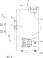
- the secondary circuit 50 is designed as a heat pump circuit and has, according to Fig. 6 an evaporator 51, a compressor 52, two condensers 53-1, 53-2; 53-1', 53-2' and a throttle 54.
- the evaporator 51 functions as a heat exchanger 31, wherein the heat is transferred from the coolant of the primary circuit 40 to the refrigerant of the secondary circuit 50 by evaporating the refrigerant, and is designed in the form of a plate heat exchanger.
- the refrigerant After evaporation, the refrigerant is passed successively through the compressor 52, through the second condenser 53-2; 53-2' and through the first condenser 53-1; 53-1', wherein heat is dissipated in the condensers 53-1, 53-2; 53-1', 53-2' by condensing the refrigerant.
- the liquid refrigerant After condensation of the refrigerant, the liquid refrigerant is expanded in the throttle 54 and then fed back to the evaporator 51 to absorb heat from the coolant.
- the first condenser 53-1; 53-1 ⁇ is assigned to the driver's cabin 20 for heating it. In this respect, heat is transferred from the coolant to the air in the driver's cabin 20 when the coolant condenses in the first condenser 53-1; 53-1'.
- the second condenser 53-2; 53-2 ⁇ is assigned to the environment or the ambient air of the snowcat 1, so that heat is released to the ambient air when the coolant condenses in the second condenser 53-2; 53-2'.
- the total amount of heat released via the secondary circuit 50 is the sum of the amount of heat released via the first condenser 53-1; 53-1' and the second condenser 53-2; 53-2' and essentially corresponds to a cooling capacity of the heat transfer system.
- the condensers 53-1, 53-2 are arranged in a floor assembly 26 of the driver's cab 20 in the driver's cab 20.
- the floor assembly 26 forms a tunnel-like region in which the condensers 53-1, 53-2 are arranged.
- the tunnel-like region runs below and in the middle of two vehicle seats 21 arranged in the driver's cab 20 and thus forms a central tunnel.
- the second condenser 53-2 is arranged on the floor of the floor assembly 26 so that air flowing around it is blown in the direction of the runway on which the snow groomer 1 is moving or standing.
- the first condenser 53-1 is arranged above the second condenser 53-2 so that air flowing around it is blown forward in the direction of travel of the snow groomer 1.
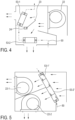
- a radial fan 22 and a control flap 23 controlled by an actuator 24 are provided in the floor assembly 26.
- the radial fan 22 is arranged behind the condensers 53-1, 53-2 and laterally offset from them, as shown in Fig. 4
- the radial fan 22 generates an air flow that is passed over the condensers 53-1, 53-2.
- heat is transferred from the coolant flowing through the condensers 53-1, 53-2 to the air flowing around the condensers 53-1, 53-2 and the heat is then passed on into the driver's cab 20 or dissipated to the environment by means of the air flow.
- the air flowing over the second condenser 53-2 is directed downwards towards the chassis or the runway after flowing around the second condenser 53-2.
- the air flowing over the first condenser 53-1 is directed, after flowing around the first condenser 53-1, into an air distribution box 27 arranged at the front of the driver's cab 20, which distributes the heated air in the driver's cab 20.
- the radial fan 22 sucks in the fresh air to be supplied to the condensers 53-1, 53-2 from the environment via air inlet slots 28 in the B-pillar of the driver's cab 20, sucks it through an air duct in the B-pillar and blows it out in flow proportions set by means of the control flap 23. via the two capacitors 53-1, 53-2.
- the air flow through the air inlet slots 28, through the air duct and the radial fan 22 and via the capacitors 53-1, 53-2 into the environment or into the air distribution box 27 is in Fig. 3 illustrated by appropriately directed arrows.
- Fig. 2 shows an alternative arrangement of the capacitors 53-1, 53-2.
- the first capacitor 53-1 is positioned below a vehicle seat 21 in the driver's cab 20 to release heat directly into the driver's cab 20 and the second capacitor 53-2 is positioned on an outer wall or floor of the driver's cab 20 (not shown) to release heat directly into the environment.
- the arrangement of the first capacitor 53-1 below the vehicle seat 21 can be advantageous in snow groomers 1 with only a single vehicle seat 21 in the driver's cab 20 provided for a driver of the snow groomer. The heated air can then be fed directly to an operator of the snow groomer 1 sitting on the vehicle seat 21.
- the control flap 23 serves to divide the air flow into flow components flowing via the first condenser 53-1 and the second condenser 53-2.
- the control flap 23 can be optionally adjusted in the range between a first end position and a second end position. In the first end position, the control flap 23 completely closes off the flow path of the air flow from the radial fan 22 into the environment, so that the air flow is completely directed via the first condenser 53-1 and into the driver's cab 20, and in the second end position it completely closes off the flow path of the air flow from the radial fan 22 into the driver's cab 20, so that the air flow is completely directed via the second condenser 53-2 and into the environment.
- the control flap 23 can assume any position between the first and second end positions and thus divide the air flow into corresponding flow components.
- Fig. 5 shows an alternative embodiment.
- a single condenser with two condenser regions 53-1', 53-2' is provided in the secondary circuit 50, with a first condenser region 53-1' being assigned to the driver's cab 20 for dissipating heat to the air in the driver's cab 20 and a second condenser region 53-2' being assigned to the environment for dissipating heat to the ambient air.
- two air flows are guided separately over the first and second condenser regions 53-1', 53-2'.
- two radial fans 22-1', 22-2' are provided behind the condenser regions 53-1', 53-2' in the air flow direction, which generate the air flows over the respective condenser region 53-1', 53-2'.
- the heated air is then blown by the radial fans 22-1', 22-2 ⁇ into the driver's cabin 20 or into the Environment.
- the two capacitor areas 53-1', 53-2 ⁇ thus fulfil the same function as the two capacitors 53-1, 53-2 of the Fig. 4 embodiment shown.
- the radial fans 22-1', 22-2' independently of one another, individual air flows or flow components assigned to the respective condenser area 53-1', 53-2' can be generated. For example, if there is no heating requirement in the driver's cab 20, the radial fan 22-1' assigned to the first condenser area 53-1' can stand still, while the radial fan 22-2' assigned to the second condenser area 53-2' is driven according to a cooling requirement of the drive system 10. Accordingly, in the event that the heating requirement in the driver's cab 20 corresponds to a cooling requirement of the drive system, the second radial fan 22-2' can stand still and the first radial fan 22-1' can be driven according to the heating requirement or the cooling requirement.
- two condensers 53-1, 53-2 are provided in the secondary circuit 50 and two radial fans 22-1', 22-2' are arranged in the flow direction behind a respective associated condenser 53-1, 53-2 and generate a respective air flow via the condenser 53-1, 53-2.
- the heat of the drive system 10 transferred to the coolant in the primary circuit 40 can be used to heat the driver's cab 20 by means of the secondary circuit 50. If the cooling requirement of the drive system 10 exceeds a heating requirement of the driver's cab 20, i.e. if the heat to be absorbed by the drive system 10 in the primary circuit 40 is greater than the amount of heat to be released into the driver's cab 20 in the secondary circuit 50, the excess heat, i.e. the difference between the cooling and heating requirements, can be conducted into the environment.
- the actuator 24 adjusts according to the Fig. 4
- the control flap 23 is in a corresponding position in which it divides the air flow generated by the radial fan 22 into the flow components assigned to the condensers 53-1, 53-2, so that an amount of heat emitted into the driver's cab 20 corresponds to a desired heating requirement and the remaining heat is emitted to the environment.
- the first radial fan 22-1' is controlled so that the heating requirement in the driver's cab 20 is covered, and the second radial fan 22-2' is controlled so that the heat emitted via both capacitors 53-1, 53-2 or via both capacitor areas 53-1', 53-2' serves the cooling requirement of the drive system.
- the primary circuit 40 is divided into two primary circuit branches 41-1, 41-2, wherein the first primary circuit branch 41-1 is assigned to the drive devices 11-1, 11-2, 11-3 and the second primary circuit branch 41-2 is assigned to the traction batteries B1, B2 for their respective cooling.
- the heat exchanger 31 is provided in the second primary circuit branch 41-2 so that heat from the primary circuit 40 can be dissipated via the second primary circuit branch 41-2.
- the first and second primary circuit branches 41-1, 41-2 are connected to one another via a common circuit section 42.
- the first and second primary circuit branches 41-1, 41-2 merge at the beginning of the circuit section 42 and the circuit section 42 splits into the two primary circuit branches 41-1, 41-2 at the end of the circuit section 42.
- the coolant in the first primary circuit branch 41-1 and the coolant in the second primary circuit branch 41-2 mix.
- a coolant pump 43-1, 43-2 is provided in each of the primary circuit branches 41-1, 41-2, which generates the circulation of the coolant in the respective primary circuit branch 41-1, 41-2.
- the coolant pumps 43-1, 43-2 By dimensioning or controlling the coolant pumps 43-1, 43-2 differently, different volume flows can be generated in the primary circuit branches 41-1, 41-2.
- the volume flow In the first primary circuit branch 41-1, the volume flow is approximately 60 liters per minute and in the second primary circuit branch 41-2 approximately 20 liters per minute.
- an operating temperature of the converters U1-3 and the electric motors M1-3 can be higher than an operating temperature of the traction batteries B1, B2, so that a temperature of the coolant in the first primary circuit branch 41-1 is higher than a temperature of the coolant in the second primary circuit branch 41-2.
- the temperature of the coolant in the first primary circuit branch 41-1 is approximately 30 °C and in the second primary circuit branch 41-2 approximately 21 °C.
- the differently tempered coolants assigned to the respective primary circuit branches 41-1, 41-2 meet and the mixing results in a heat exchange or temperature equalization. Heat is transferred from the coolant coming from the drive devices 11-1, 11-2, 11-3 to the coolant coming from the traction batteries B1, B2.
- the coolant in the second The coolant flowing in the primary circuit branch 41-2 transfers heat to the coolant in the secondary circuit 50 as it passes through the heat exchanger 31 and is then fed again to the traction batteries B1, B2, while the coolant flowing in the first primary circuit branch 41-1 is fed again to the drive devices 11-1, 11-2, 11-3.
- a heating device 32 is also provided in the second primary circuit branch 41-2.
- the heating device 32 can be used to heat the coolant in the second primary circuit branch 41-2.
- the heat supplied to the primary circuit 40 by the heating device 32 can be used indirectly to heat the driver's cab 20.
- the cooling circuit and thus the heating of the driver's cab 20 can also be operated at low cold start temperatures.
- a cooling water temperature can be raised to a suitable level for the cooling circuit, in particular by a preheating process.
- the heat supplied via the heating device 32 can be used to regulate the temperature of the traction batteries B1, B2 connected downstream of the heat exchanger 31 and, if necessary, also to regulate the temperature of the drive devices 11-1, 11-2, 11-3.
Landscapes
- Engineering & Computer Science (AREA)
- Physics & Mathematics (AREA)
- Mechanical Engineering (AREA)
- Thermal Sciences (AREA)
- Structural Engineering (AREA)
- Civil Engineering (AREA)
- Architecture (AREA)
- Life Sciences & Earth Sciences (AREA)
- Sustainable Development (AREA)
- Sustainable Energy (AREA)
- Mining & Mineral Resources (AREA)
- General Engineering & Computer Science (AREA)
- Air-Conditioning For Vehicles (AREA)
Abstract
Ziviles Kettenfahrzeug aufweisend ein Antriebssystem (10), das zum Bereitstellen von Antriebsenergie eingerichtet ist, eine Fahrerkabine und ein dem Antriebssystem (10) und der Fahrerkabine zugeordnetes Wärmeübertragungssystem, das einen Primärkreislauf (40) zur Aufnahme eines darin zirkulierenden Kühlmittels, einen Sekundärkreislauf (50) zur Aufnahme eines darin zirkulierenden Kältemittels und einen Wärmeübertrager (31) umfasst, der den Primärkreislauf (40) und den Sekundärkreislauf (50) thermisch miteinander koppelt, wobei der Primärkreislauf (40) zur Kühlung des Antriebssystems (10) durch Übertragung von Abwärme des Antriebssystems (10) auf das Kühlmittel eingerichtet ist, wobei der Wärmeübertrager (31) zur Übertragung von Wärme vom Kühlmittel des Primärkreislaufs (40) auf das Kältemittel des Sekundärkreislaufs (50) eingerichtet ist, und wobei der Sekundärkreislauf (50) zur Abgabe von Wärme an die Raumluft in der Fahrerkabine sowie an die Umgebungsluft durch Abkühlen des Kältemittels eingerichtet ist.
Description
- Die Erfindung betrifft ein ziviles Kettenfahrzeug aufweisend ein Antriebssystem, das zum Bereitstellen von Antriebsenergie eingerichtet ist, eine Fahrerkabine sowie ein dem Antriebssystem und der Fahrerkabine zugeordnetes Wärmeübertragungssystem, das einen Primärkreislauf zur Aufnahme eines darin zirkulierenden Kühlmittels, einen Sekundärkreislauf zur Aufnahme eines darin zirkulierenden Kältemittels und einen Wärmeübertrager umfasst, der den Primärkreislauf und den Sekundärkreislauf thermisch miteinander koppelt, wobei der Primärkreislauf zu Kühlung des Antriebssystems durch Übertragung von Abwärme des Antriebssystems auf das Kühlmittel eingerichtet ist und wobei der Wärmeübertrager zur Übertragung von Wärme vom Kühlmittel des Primärkreislaufs auf das Kältemittel des Sekundärkreislaufs eingerichtet ist.
- Ein derartiges Kettenfahrzeug aufweisend ein Wärmeübertragungssystem mit Primär- und Sekundärkreislauf zum Kühlen eines Antriebssystems ist allgemein bekannt. Die von dem Antriebssystem solcher Kettenfahrzeuge auf ein Kühlmittel des Primärkreislaufs übertragene Wärme wird auf ein Kältemittel eines ersten Sekundärkreislaufs zum Beheizen einer Fahrerkabine und auf ein Kältemittel eines zweiten Sekundärkreislaufs zur Abgabe an die Umgebungsluft übertragen.
- Aufgabe der Erfindung ist es, ein Kettenfahrzeug der eingangs genannten Art zu schaffen, das eine verbesserte Kühlung des Antriebssystems bei gleichzeitig verbesserter Temperierung der Fahrerkabine ermöglicht.
- Diese Aufgabe wird dadurch gelöst, dass der Sekundärkreislauf zur Abgabe von Wärme an die Raumluft in der Fahrerkabine sowie an die Umgebungsluft durch Abkühlen des Kältemittels eingerichtet ist. Damit ist gemeint, dass nur ein einziger Sekundärkreislauf zum Abführen von Wärme vom Primärkreislauf vorgesehen ist. Die Verwendung eines Sekundärkreislaufs sowohl zum Beheizen der Fahrerkabine als auch zur Abgabe von Wärme an die Umgebungsluft kann mehrere Vorteile gegenüber der Verwendung von zwei Sekundärkreisläufen ermöglichen. Die Einsparung eines Sekundärkreislaufs ermöglicht einen einfacheren Aufbau des Wärmeübertragungssystems und einen geringeren Installationsaufwand sowie geringere Kosten und Gewicht. Zudem weist das Wärmeübertragungssystem nur mehr einen einzigen Wärmeübergang vom Kühlmittel zum Kältemittel bzw. nur einen einzigen Wärmeübertrager und damit eine höhere Effizienz der Wärmeübertragung auf. Dadurch kann Wärme vom Primärkreislauf auf den Sekundärkreislauf effizienter übertragen und in vorteilhafter Weise zur Beheizung der Fahrerkabine genutzt oder gegebenenfalls in die Umgebung abgeführt werden. Gleichzeitig kann dadurch mehr Wärme vom Antriebssystem des Kettenfahrzeugs abgeführt werden, wodurch eine Kühlleistung des Primärkreislaufs steigt. Der Wärmeübertrager kann auch als Wärmetauscher bezeichnet werden. Des Weiteren können der Primärkreislauf und der Sekundärkreislauf auch als Kühlmittelkreislauf bzw. Kältemittelkreislauf bezeichnet werden.
- In Ausgestaltung der Erfindung weist der Sekundärkreislauf zwei hintereinander, d.h. seriell, geschaltete Kondensatoren zur Wärmeabgabe auf und ist zum Führen des Kältemittels nacheinander durch die beiden Kondensatoren hindurch eingerichtet. Dabei ist ein erster Kondensator der Fahrerkabine zur Abgabe von Wärme an die Raumluft in der Fahrerkabine und ein zweiter Kondensator der Umgebung zur Abgabe von Wärme an die Umgebungsluft zugeordnet. Die Kondensatoren ermöglichen eine effiziente Wärmeabgabe vom Kältemittel an die Raumluft und an die Umgebungsluft. Bei flacher Bauart lassen sich die Kondensatoren einfach an geeigneten Positionen am Kettenfahrzeug positionieren. Der Einsatz von zwei Kondensatoren ermöglicht eine hohe Wärmeabgabe des Kältemittels im Sekundärkreislauf. Wenn der eine Kondensator Wärme an die Umgebung abgibt, kondensiert das Kältemittel bereits dort, so dass der andere Kondensator der Fahrerkabine kalt bleibt, wenn dort kein Heizbedarf besteht. Wenn Heizbedarf besteht, dann gibt der der Fahrerkabine zugeordnete Kondensator Wärme an die Fahrerkabine ab. Die Bezeichnung der Kondensatoren als "erster" und "zweiter" dient lediglich deren Unterscheidung und definiert insbesondere keine Reihenfolge der Anordnung im Sekundärkreislauf. Mit anderen Worten kann das Kältemittel den ersten und den zweiten Kondensator in beliebiger Reihenfolge durchströmen, d.h. zunächst durch den der Umgebung und dann durch den der Fahrerkabine zugeordneten Kondensator, oder umgekehrt. Der Kondensator kann auch als Verflüssiger bezeichnet werden.
- Die beiden Kondensatoren können bei einer alternativen Ausgestaltung auch in Form eines einzelnen Kondensators mit zwei Kondensatorbereichen ausgebildet sein, wobei je ein Kondensatorbereich der Fahrerkabine und der Umgebung zugeordnet ist. Das Kältemittel wird nacheinander durch die beiden Kondensatorbereiche hindurchgeführt. Über den jeweiligen Kondensatorbereich ist eine Abgabe von Wärme in die Fahrerkabine und an die Umgebung möglich.
- In weiterer Ausgestaltung der Erfindung ist im Sekundärkreislauf wenigstens ein vom Kältemittel durchströmter Kondensator und wenigstens ein Lüfter vorgesehen, der zur Erzeugung eines Luftstroms über den Kondensator zur Übertragung von Wärme vom Kältemittel auf den Luftstrom zur Abfuhr der Wärme mittels des erwärmten Luftstroms an die Raumluft der Fahrerkabine und an die Umgebungsluft eingerichtet ist. Hierzu ist der Kondensator im Strömungsweg des Luftstroms angeordnet. Die Verwendung eines Lüfters zur Erzeugung eines Luftstroms zur Kühlung der Kondensatoren stellt eine einfache Realisierung der Kühlung der Kondensatoren dar, insbesondere gegenüber beispielsweise wassergekühlten Kondensatoren, die eine Wasserzufuhr und Wasserabfuhr benötigen. Zudem ermöglicht die Kühlung des Kondensators mittels des Luftstroms eine vorteilhafte Verteilung der am Kondensator abgegebenen Wärme in der Fahrerkabine. Optional kann zusätzlich bei einer Fortbewegung des Kettenfahrzeugs ein Fahrtwind zu Kühlung des Kondensators genutzt werden. Falls im Sekundärkreislauf zwei Kondensatoren vorgesehen sind, kann der durch den Lüfter erzeugte Luftstrom zur Kühlung beider Kondensatoren verwendet werden. Der Lüfter kann auch als Ventilator oder Gebläse bezeichnet werden.
- In weiterer Ausgestaltung der Erfindung weist das Kettenfahrzeug eine Steuerklappe zum Leiten des durch den Lüfter erzeugten Luftstroms über die Kondensatoren und einen Stellantrieb zum Ansteuern der Steuerklappe auf. Die Steuerklappe ist dazu eingerichtet, den Luftstrom in einen ersten Strömungsanteil, der über den ersten Kondensator leitbar ist, und einer zweiten Strömungsanteil aufzuteilen, der über den zweiten Kondensator leitbar ist. Durch die Verwendung der Steuerklappe ist bei Verwendung nur eines Lüfters der Luftstrom in zwei Strömungsanteile aufteilbar und über einen jeweiligen Kondensator zur Wärmeabfuhr leitbar. Durch die Steuerklappe kann vorteilhafterweise das Verhältnis der beiden Strömungsanteile zueinander und damit das Verhältnis der Wärmeabgabe am ersten und am zweiten Kondensator eingestellt werden. Vorteilhaft steuert der Stellantrieb die Steuerklappe abhängig vom Heizbedarf in der Fahrerkabine und vom Kühlbedarf des Antriebssystems an und bewirkt eine entsprechende Verteilung der abgegebenen Wärme bzw. der Strömungsanteile. Ein etwaiger Wärmeüberschuss kann über den der Umgebung zugeordneten Kondensator abgegeben werden. Optional kann ein Volumenstrom des durch den Lüfter erzeugten Luftstroms durch entsprechende Ansteuerung des Lüfters abhängig vom Heizbedarf und vom Kühlbedarf eingestellt werden.
- Bei einer alternativen Ausgestaltung sind zwei oder mehr Lüfter vorgesehen, von denen je einer dem ersten und dem zweiten Kondensator zugeordnet ist. Die den Kondensatoren zugeordneten Strömungsanteile können dann unabhängig voneinander durch entsprechende Ansteuerung des jeweiligen Lüfters eingestellt werden. Eine Steuerklappe samt Stellantrieb kann bei dieser Ausgestaltung entfallen.
- In weiterer Ausgestaltung der Erfindung sind der Kondensator und der Lüfter in der Fahrerkabine angeordnet. Die Anordnung in der Fahrerkabine ermöglicht einen kurzen Weg des Luftstroms vom Lüfter über den Kondensator und in die Fahrerkabine und damit eine effektive Beheizung der Fahrerkabine. Zudem ermöglicht das Anordnen der Komponenten in der Fahrerkabine eine kompakte Bauweise. Bei Verwendung von zwei Kondensatoren im Sekundärkreislauf sind vorteilhaft beide Kondensatoren in der Fahrerkabine positioniert. Besonders vorteilhaft ist der der Umgebung zugeordnete, zweite Kondensator nahe einer Außenwand oder einem Boden der Fahrerkabine angeordnet, sodass bei Verwendung eines einzigen Lüfters der Luftstrom einerseits auf kurzem Weg über den ersten Kondensator und in die Fahrerkabine für eine unmittelbare Beheizung der Fahrerkabine und andererseits auf kurzem Weg über den zweiten Kondensator und in die Umgebung zur unmittelbaren Wärmeabfuhr an die Umgebungsluft gelangen kann. Besonders vorteilhaft ist auch die Steuerklappe in der Fahrerkabine angeordnet und dazu eingerichtet, einen Strömungsweg des Luftstroms vom Lüfter in die Umgebung zu verschließen.
- In weiterer Ausgestaltung der Erfindung realisiert der Sekundärkreislauf einen Wärmepumpenkreislauf und weist hierzu einen Verdampfer, einen Kompressor, wenigstens einen Kondensator und eine Drossel auf. Der Verdampfer ist zur Übertragung von Wärme vom Kühlmittel des Primärkreislaufs auf das Kältemittel des Sekundärkreislaufs eingerichtet und der Kondensator ist zur Abgabe von Wärme vom Kältemittel an die Raumluft in der Fahrerkabine und an die Umgebungsluft eingerichtet. Durch die Wärmepumpe ist eine Beheizung der Fahrerkabine in energiesparender Weise möglich. Der Verdampfer des Wärmepumpenkreislaufs wird durch den Wärmeübertrager bereitgestellt, der den Primärkreislauf mit dem Sekundärkreislauf thermisch koppelt, und ermöglicht die Übertragung von Wärme vom Kühlmittel auf das Kältemittel durch Verdampfen des Kältemittels im Verdampfer bzw. Wärmeübertrager. Der Kompressor kann auch als Verdichter bezeichnet werden.
- Optional ist im Sekundärkreislauf eine Heizeinrichtung vorgesehen. Diese kann ein Zuführen von Wärme zur Raumluft der Fahrerkabine unterstützen.
- In weiterer Ausgestaltung der Erfindung ist im Primärkreislauf eine Heizeinrichtung vorgesehen, die zur Erwärmung des Kühlmittels eingerichtet ist. Diese Anordnung ermöglicht neben dem Abführen von Wärme vom Antriebssystem eine zusätzliche Wärmezufuhr in den Sekundärkreislauf, insbesondere zum Beheizen der Fahrerkabine. Das bedeutet, die Heizeinrichtung kann eine Wärmezufuhr zum Sekundärkreislauf zwecks Beheizung der Fahrerkabine unterstützen oder ermöglichen. Insbesondere kann dadurch auch bei einem (noch) kalten Antriebssystem, beispielsweise unmittelbar nach dem Start des Antriebssystems, die Fahrerkabine geheizt werden. Zudem ermöglicht die Heizeinrichtung eine Wärmezufuhr zum Primärkreislauf, insbesondere zum Antriebssystem. Dies kann beispielsweise erwünscht sein, um das Antriebssystem in kürzerer Zeit auf Betriebstemperatur zu bringen oder um das Antriebssystem auch bei sehr niedrigen Umgebungstemperaturen auf Betriebstemperatur zu halten.
- In weiterer Ausgestaltung der Erfindung ist das Kettenfahrzeug als elektrisch angetriebenes Kettenfahrzeug ausgeführt mit wenigstens einer elektrischen Antriebseinrichtung zum Bereitstellen von Antriebsleistung und wenigstens einem elektrischen Energiespeicher zum Bereitstellen von elektrischer Energie zur Antriebseinrichtung. Der Primärkreislauf ist zur Kühlung der Antriebseinrichtung und/oder des Energiespeichers eingerichtet. Durch die Ausführung als elektrisch angetriebenes Kettenfahrzeug ist ein emissionsarmer Betrieb des Kettenfahrzeugs möglich. Die Antriebseinrichtung und der Energiespeicher bilden das Antriebssystem des Kettenfahrzeugs, gegebenenfalls gemeinsam mit weiteren Komponenten, insbesondere mit einem oder mehreren Umrichtern. Vorteilhaft ist der elektrische Energiespeicher eine Batterie oder ein Akkumulator.
- In weiterer Ausgestaltung der Erfindung ist der Primärkreislauf in einen ersten Primärkreislaufzweig, der zum Kühlen der Antriebseinrichtung eingerichtet ist, und einen zweiten Primärkreislaufzweig aufgeteilt, der zum Kühlen des Energiespeichers und zur Übertragung von Wärme vom Kühlmittel auf das Kältemittel des Sekundärkreislaufs eingerichtet ist. Der erste und der zweite Primärkreislaufzweig sind zum Austausch des Kühlmittels eingerichtet. Dies ermöglicht ein zumindest teilweises Entkoppeln der Kühlung der Antriebseinrichtung von der Kühlung des Energiespeichers. Dadurch brauchen die Antriebseinrichtung und der Energiespeicher nicht auf dieselbe Temperatur gekühlt werden. In anderen Worten brauchen die Antriebseinrichtung und der Energiespeicher nicht denselben Kühlbedarf aufweisen. Vorteilhaft weist der Primärkreislauf einen Kreislaufabschnitt auf, der beiden Primärkreislaufzweigen gemeinsam ist, d.h. den diese teilen, sodass in dem gemeinsamen Kreislaufabschnitt das Kühlmittel des ersten und des zweiten Primärkreislaufzweigs gemeinsam fließen und sich dabei durchmischen. Besonders vorteilhaft ist der Kreislaufabschnitt in Strömungsrichtung des Kühlmittels hinter Komponenten des Antriebssystems, wie der Antriebseinrichtung und/oder dem Energiespeicher, angeordnet, sodass eine größtmögliche thermische Entkopplung der beiden Primärkreislaufzweige erreicht werden kann, ohne dass beispielsweise die Abwärme der Antriebseinrichtung zu einer übermäßigen Erwärmung des Energiespeichers führt.
- Vorteilhaft ist die Heizeinrichtung im zweiten Primärkreislaufzweig aufweisend den Wärmeübertrager und den Energiespeicher vorgesehen, sodass eine möglichst unmittelbare Wärmezufuhr zum Sekundärkreislauf und zum Energiespeicher bei gleichzeitig möglichst geringer Wärmezufuhr zum ersten Primärkreislaufzweig mit der Antriebseinrichtung bereitgestellt ist.
- In weiterer Ausgestaltung der Erfindung weist das Kühlmittel im ersten Primärkreislaufzweig einen höheren durchschnittlichen Volumenstrom und eine höhere durchschnittliche Temperatur als das Kühlmittel im zweiten Primärkreislaufzweig auf. Dadurch kann im ersten Primärkreislaufzweig von der Antriebseinrichtung mehr Wärme bei einer höheren Kühlmitteltemperatur abgeführt werden als im zweiten Primärkreislaufzweig vom Energiespeicher bei einer niedrigeren Kühlmitteltemperatur. Vorteilhaft ist im jeweiligen Primärkreislaufzweig die Temperatur und der Volumenstrom des Kühlmittels auf den Kühlbedarf und die Betriebstemperatur der im Primärkreislaufzweig vorgesehenen, zu kühlenden Komponenten abgestimmt.
- Weitere Vorteile und Merkmale der Erfindung ergeben sich aus den Ansprüchen sowie aus der nachfolgenden Beschreibung eines bevorzugten Ausführungsbeispiels der Erfindung, das anhand der Zeichnungen dargestellt ist.
- Fig. 1
- zeigt eine Perspektivansicht eines erfindungsgemäßen Kettenfahrzeugs mit einer Fahrerkabine,
- Fig. 2
- eine Innenansicht der Fahrerkabine des Kettenfahrzeugs nach
Fig. 1 , - Fig. 3
- eine Perspektivansicht der Fahrerkabine des Kettenfahrzeugs nach
Fig. 1 von schräg unten, - Fig. 4
- schematisch einen Ausschnitt eines Sekundärkreislaufs eines Wärmeübertragungssystems des Kettenfahrzeugs nach
Fig. 1 , - Fig. 5
- schematisch einen Ausschnitt eines alternativen Sekundärkreislaufs des Wärmeübertragungssystems des Kettenfahrzeugs nach
Fig. 1 , - Fig. 6
- eine blockdiagrammartige Darstellung des Wärmeübertragungssystems des Kettenfahrzeugs nach
Fig. 1 . -
Fig. 1 zeigt ein erfindungsgemäßes ziviles Kettenfahrzeug in Form einer Pistenraupe 1, die zur Fortbewegung auf einer Piste eingerichtet ist. Zu diesem Zweck weist die Pistenraupe 1 ein Kettenfahrwerk 2 auf, das auf einander gegenüberliegenden Seiten eines Tragrahmens 5 der Pistenraupe 1 jeweils ein Kettenlaufwerk 3 umfasst. Die Pistenraupe 1 ist mit einem Antriebssystem 10 ausgestattet, das zum Antreiben der Kettenlaufwerke 3 eingerichtet ist. Hierzu weist das Antriebssystem 10 jeweils einen, den Kettenlaufwerken 3 zugeordneten Fahrantrieb und jeweils einen den Fahrantrieben zugeordneten Elektromotor M1, M3 sowie jeweils einen den Elektromotoren M1, M3 zugeordneten Umrichter U1, U3 auf. Ferner weist die Pistenraupe 1 einen weiteren Elektromotor M2 zum Antrieb eines Fräsantriebs, der einer an der Pistenraupe 1 vorgesehenen Heckfräse 4 zugeordnet ist, sowie einen dem Elektromotor M2 zugeordneten Umrichter U2 auf. Die Umrichter U1 bis U3 zählen zu einer für den Betrieb der Elektromotoren M1 bis M3 notwendige Leistungselektronik. Die Fahrantriebe und der Fräsantrieb sind als hydraulische Antriebseinheiten ausgebildet. Die Antriebseinheiten bilden mit dem jeweils zugeordneten Elektromotor M1-3 und Umrichter U1-3 eine Antriebseinrichtung 11-1, 11-2, 11-3 der Pistenraupe 1. Zudem weist die Pistenraupe 1 zwei elektrische Energiespeicher in Form von Traktionsbatterien B1, B2 zur Speisung der Elektromotoren M1-3 mit elektrischer Energie auf. Die Fahr- und Fräsantriebe, die Umrichter U1-3, die Elektromotoren M1-3 und die Traktionsbatterien B1, B2 sind samt einer Fahrerkabine 20 auf dem Tragrahmen 5 montiert. - Dem Antriebssystem 10 und der Fahrerkabine 20 ist ein Wärmeübertragungssystem 30 gemäß den
Fig. 4 bis 6 zugeordnet. Das Wärmeübertragungssystem 30 weist einen Primärkreislauf 40 auf, in dem ein Kühlmittel zirkuliert. Der Primärkreislauf 40 ist den Antriebseinrichtungen 11-1, 11-2, 11-3 und den Traktionsbatterien B1, B2 zu deren Kühlung zugeordnet. Zu diesem Zweck nimmt das in den Primärkreislauf 40 zirkulierende Kühlmittel Abwärme des Antriebssystems 10 auf und führt die Wärme ab. Zur Kühlung der Antriebseinrichtungen 11-1, 11-2, 11-3 wird das Kühlmittel so geführt, dass es zunächst Abwärme von den Elektromotoren M1-3 und dann Abwärme der Umrichter U1-3 aufnimmt und abführt. - Neben dem Primärkreislauf 40 weist das Wärmeübertragungssystem 30 einen Sekundärkreislauf 50 auf. Der Sekundärkreislauf 50 ist mit dem Primärkreislauf 40 über einen Wärmeübertrager 31 thermisch gekoppelt. Mittels des Wärmeübertragers 31 ist Wärme von dem Kühlmittel auf ein in dem Sekundärkreislauf 50 zirkulierendes Kältemittel übertragbar. Vorteilhaft enthält das Kühlmittel Wasser, Glykol oder eine Mischung der beiden und das Kältemittel enthält das Kältemittel R-134a.
- Der Sekundärkreislauf 50 ist als ein Wärmepumpenkreislauf ausgebildet und weist hierzu gemäß
Fig. 6 einen Verdampfer 51, einen Kompressor 52, zwei Kondensatoren 53-1, 53-2; 53-1', 53-2' und eine Drossel 54 auf. Der Verdampfer 51 fungiert als Wärmeübertrager 31, wobei die Wärme vom Kühlmittel des Primärkreislaufs 40 auf das Kältemittel des Sekundärkreislaufs 50 durch Verdampfen des Kältemittels übertragen wird, und ist in Form eines Plattenwärmetauschers ausgebildet. Nach dem Verdampfen wird das Kältemittel nacheinander durch den Kompressor 52, durch den zweiten Kondensator 53-2; 53-2' und durch den ersten Kondensator 53-1; 53-1' geleitet, wobei in den Kondensatoren 53-1, 53-2; 53-1', 53-2' unter Kondensation des Kältemittels Wärme abgeführt wird. Nach der Kondensation des Kältemittels wird das flüssige Kältemittel in der Drossel 54 entspannt und dann wieder dem Verdampfer 51 zur Aufnahme von Wärme vom Kühlmittel zugeführt. - Der erste Kondensator 53-1; 53-1` ist der Fahrerkabine 20 zu deren Beheizung zugeordnet. Insofern wird unter Kondensation des Kältemittels im ersten Kondensator 53-1; 53-1' Wärme von dem Kältemittel an die Raumluft der Fahrerkabine 20 übertragen. Der zweite Kondensator 53-2; 53-2` ist der Umgebung bzw. der Umgebungsluft der Pistenraupe 1 zugeordnet, sodass unter Kondensation des Kältemittels im zweiten Kondensator 53-2; 53-2' Wärme an die Umgebungsluft abgegeben wird. Die über den Sekundärkreislauf 50 insgesamt abgegebene Wärmemenge ergibt sich als die Summe der über den ersten Kondensator 53-1; 53-1' und den zweiten Kondensator 53-2; 53-2' jeweils abgegebenen Wärmemenge und entspricht im Wesentlichen einer Kühlleistung des Wärmeübertragungssystems.
- Entsprechend der in
Fig. 3 gezeigten Ausführungsform, sind die Kondensatoren 53-1, 53-2 in einer Bodengruppe 26 der Fahrerkabine 20 in der Fahrerkabine 20 angeordnet. Die Bodengruppe 26 bildet einen tunnelartigen Bereich aus, in dem die Kondensatoren 53-1, 53-2 angeordnet sind. Der tunnelartige Bereich verläuft unterhalb von und mittig zu zwei in der Fahrerkabine 20 angeordneten Fahrzeugsitzen 21 und bildet somit einen Mitteltunnel. Der zweite Kondensator 53-2 ist am Boden der Bodengruppe 26 angeordnet, sodass ihn umströmende Luft in Richtung der Piste geblasen wird, auf dem sich die Pistenraupe 1 fortbewegt oder steht. Der erste Kondensator 53-1 ist oberhalb des zweiten Kondensators 53-2 angeordnet, sodass ihn umströmende Luft in Fahrtrichtung der Pistenraupe 1 nach vorn geblasen wird. - Zudem sind in der Bodengruppe 26 ein Radiallüfter 22 sowie eine über einen Stellantrieb 24 ansteuerbare Steuerklappe 23 vorgesehen. Der Radiallüfter 22 ist hinter den Kondensatoren 53-1, 53-2 und seitlich zu diesen versetzt angeordnet, wie in
Fig. 4 zu sehen. Der Radiallüfter 22 erzeugt einen Luftstrom, der über die Kondensatoren 53-1, 53-2 geleitet wird. Beim Umströmen der Kondensatoren 53-1, 53-2 findet eine Übertragung von Wärme vom die Kondensatoren 53-1, 53-2 durchströmenden Kältemittel auf die die Kondensatoren 53-1, 53-2 umströmende Luft statt und die Wärme wird dann mittels des Luftstroms weiter in die Fahrerkabine 20 geleitet bzw. an die Umgebung abgeführt. - Die über den zweiten Kondensator 53-2 strömende Luft wird nach Umströmen des zweiten Kondensators 53-2 nach unten in Richtung des Fahrgestells bzw. der Piste unmittelbar in die Umgebung geleitet. Die über den ersten Kondensator 53-1 strömende Luft wird nach Umströmen des ersten Kondensators 53-1 in einen frontseitig in der Fahrerkabine 20 angeordneten Luftverteilerkasten 27 geleitet, der die erwärmte Luft in der Fahrerkabine 20 verteilt. Der Radiallüfter 22 saugt die den Kondensatoren 53-1, 53-2 zuzuführende Frischluft über Lufteinlassschlitze 28 in der B-Säule der Fahrerkabine 20 aus der Umgebung an, saugt sie durch einen Luftkanal in der B-Säule und bläst sie in mittels der Steuerklappe 23 eingestellten Strömungsanteilen über die beiden Kondensatoren 53-1, 53-2. Der Luftstrom durch die Lufteinlassschlitze 28, durch den Luftkanal und den Radiallüfter 22 hindurch und über die Kondensatoren 53-1, 53-2 in die Umgebung bzw. in den Luftverteilerkasten 27 ist in
Fig. 3 durch entsprechend gerichtete Pfeile veranschaulicht. -
Fig. 2 zeigt eine alternative Anordnung der Kondensatoren 53-1, 53-2. Bei dieser Ausführungsform ist der erste Kondensator 53-1 unterhalb eines Fahrzeugsitzes 21 in der Fahrerkabine 20 zur Abgabe von Wärme unmittelbar in die Fahrerkabine 20 und der zweite Kondensator 53-2 an einer Außenwand oder einem Boden der Fahrerkabine 20 (nicht gezeigt) zur Abgabe von Wärme unmittelbar in die Umgebung positioniert. Die Anordnung des ersten Kondensators 53-1 unter dem Fahrzeugsitz 21 kann bei Pistenraupen 1 mit lediglich einem einzigen, für einen Fahrer der Pistenraupe vorgesehenen Fahrzeugsitz 21 in der Fahrerkabine 20 vorteilhaft sein. Die erwärmte Luft kann dann unmittelbar einer auf dem Fahrzeugsitz 21 sitzenden Bedienperson der Pistenraupe 1 zugeführt werden. - Gemäß der in
Fig. 4 gezeigten Ausführungsform dient die Steuerklappe 23 zum Aufteilen des Luftstroms in über den ersten Kondensator 53-1 und den zweiten Kondensator 53-2 strömende Strömungsanteile. Dabei kann die Steuerklappe 23 wahlweise im Bereich zwischen einer ersten Endstellung und einer zweiten Endstellung verstellt werden. In der ersten Endstellung schließt die Steuerklappe 23 den Strömungsweg des Luftstroms vom Radiallüfter 22 in die Umgebung vollständig ab, sodass der Luftstrom vollständig über den ersten Kondensator 53-1 und in die Fahrerkabine 20 geleitet wird, und in der zweiten Endstellung schließt sie den Strömungsweg des Luftstroms vom Radiallüfter 22 in die Fahrerkabine 20 vollständig ab, sodass der Luftstrom vollständig über den zweiten Kondensator 53-2 und in die Umgebung geleitet wird. Die Steuerklappe 23 kann jede Stellung zwischen der ersten und zweiten Endstellung einnehmen und so den Luftstrom in entsprechende Strömungsanteile aufteilen. -
Fig. 5 zeigt eine alternative Ausführungsform. Bei dieser Ausführungsform ist ein einzelner Kondensator mit zwei Kondensatorbereichen 53-1', 53-2' im Sekundärkreislauf 50 vorgesehen, wobei ein erster Kondensatorbereich 53-1' der Fahrerkabine 20 zur Abgabe von Wärme an die Raumluft in der Fahrerkabine 20 und ein zweiter Kondensatorbereich 53-2' der Umgebung zur Abgabe von Wärme an die Umgebungsluft zugeordnet ist. Zur getrennten Abgabe von Wärme in die Fahrerkabine 20 und an die Umgebung werden zwei Luftströmungen getrennt über den ersten und den zweiten Kondensatorbereich 53-1', 53-2' geleitet. In Luftströmungsrichtung hinter den Kondensatorbereichen 53-1', 53-2' sind hierzu zwei Radiallüfter 22-1', 22-2` vorgesehen, welche die Luftströmungen über den jeweiligen Kondensatorbereich 53-1', 53-2' erzeugen. Die erwärmte Luft blasen die Radiallüfter 22-1', 22-2` dann in die Fahrerkabine 20 bzw. in die Umgebung. Die zwei Kondensatorbereiche 53-1', 53-2` erfüllen somit dieselbe Funktion wie die zwei Kondensatoren 53-1, 53-2 der inFig. 4 gezeigten Ausführungsform. - Durch entsprechende Ansteuerung der Radiallüfter 22-1', 22-2' unabhängig voneinander können dem jeweiligen Kondensatorbereich 53-1', 53-2' zugeordnete individuelle Luftströmungen bzw. Strömungsanteile erzeugt werden. Beispielsweise kann bei keinem Heizbedarf in der Fahrerkabine 20 der dem ersten Kondensatorbereich 53-1' zugeordnete Radiallüfter 22-1' stillstehen, während der dem zweiten Kondensatorbereich 53-2` zugeordnete Radiallüfter 22-2` entsprechend einem Kühlbedarf des Antriebssystems 10 angetrieben wird. Entsprechend kann in dem Fall, dass der Heizbedarf in der Fahrerkabine 20 einem Kühlbedarf des Antriebssystems entspricht, der zweite Radiallüfter 22-2' stillstehen und der erste Radiallüfter 22-1' entsprechend des Heizbedarfs bzw. des Kühlbedarfs angetrieben werden. Durch entsprechende Ansteuerung der beiden Radiallüfter 22-1', 22-2` können auf diese Weise Luftströmungen in beliebigen Strömungsanteilen über die beiden Kondensatorbereiche 53-1', 53-2` erzeugt werden und somit die Funktion des einzelnen Radiallüfters 22, der Steuerklappe 23 und des Stellantrieb 24 der Ausführungsform von
Fig. 4 in alternativer Weise erfüllt werden. - In einer nicht gezeigten Ausführungsform sind im Sekundärkreislauf 50 zwei Kondensatoren 53-1, 53-2 vorgesehen und zwei Radiallüfter 22-1', 22-2' sind in Strömungsrichtung hinter einem jeweiligen zugeordneten Kondensator 53-1, 53-2 angeordnet und erzeugen eine jeweilige Luftströmung über den Kondensator 53-1, 53-2.
- Unabhängig davon, welche der vorhergehend beschriebenen Ausführungsformen umgesetzt ist, kann die im Primärkreislauf 40 auf das Kühlmittel übertragene Wärme des Antriebssystems 10 zur Beheizung der Fahrerkabine 20 mittels des Sekundärkreislaufs 50 verwendet werden. Übersteigt der Kühlbedarf des Antriebssystems 10 einen Heizbedarf der Fahrerkabine 20, d.h. ist die im Primärkreislauf 40 aufzunehmende Wärme vom Antriebssystem 10 größer als die im Sekundärkreislauf 50 in die Fahrerkabine 20 abzugebende Wärmemenge, kann der Überschuss an Wärme, d.h. die Differenz zwischen Kühl- und Heizbedarf, in die Umgebung geleitet werden.
- Hierzu verstellt der Stellantrieb 24 gemäß der in
Fig. 4 gezeigten Ausführungsform die Steuerklappe 23 in eine entsprechende Stellung, in der sie den durch den Radiallüfter 22 erzeugten Luftstrom in die den Kondensatoren 53-1, 53-2 zugeordneten Strömungsanteile aufteilt, sodass eine in die Fahrerkabine 20 abgegebene Wärmemenge einem gewünschten Heizbedarf entspricht und die übrige Wärme an die Umgebung abgegeben wird. - Entsprechend erfolgt bei der in
Fig. 5 gezeigten Ausführungsform eine Ansteuerung des ersten Radiallüfters 22-1', sodass der Heizbedarf in der Fahrerkabine 20 gedeckt ist, und eine Ansteuerung des zweiten Radiallüfters 22-2', sodass die über beide Kondensatoren 53-1, 53-2 bzw. über beide Kondensatorbereiche 53-1', 53-2' abgegebene Wärme den Kühlbedarf des Antriebssystems bedient. - Wie in
Fig. 6 gezeigt, ist der Primärkreislauf 40 in zwei Primärkreislaufzweige 41-1, 41-2 aufgeteilt, wobei der erste Primärkreislaufzweig 41-1 den Antriebseinrichtungen 11-1, 11-2, 11-3 und der zweite Primärkreislaufzweig 41-2 den Traktionsbatterien B1, B2 jeweils zu deren Kühlung zugeordnet ist. Der Wärmeübertrager 31 ist im zweiten Primärkreislaufzweig 41-2 vorgesehen, sodass Wärme aus dem Primärkreislauf 40 über den zweiten Primärkreislaufzweig 41-2 abführbar ist. Der erste und zweite Primärkreislaufzweig 41-1, 41-2 sind über einen gemeinsamen Kreislaufabschnitt 42 miteinander verbunden. Das bedeutet, dass in Strömungsrichtung des Kühlmittels am Beginn des Kreislaufabschnitts 42 der erste und der zweite Primärkreislaufzweig 41-1, 41-2 zusammenführen und der Kreislaufabschnitt 42 sich am Ende des Kreislaufabschnitts 42 in die beiden Primärkreislaufzweige 41-1, 41-2 aufteilt. Bei Durchströmen des Kreislaufabschnitts 42 mischen sich das im ersten Primärkreislaufzweig 41-1 und das im zweiten Primärkreislaufzweig 41-2 geführte Kühlmittel. - In den Primärkreislaufzweigen 41-1, 41-2 ist jeweils eine Kühlmittelpumpe 43-1, 43-2 vorgesehen, welche die Zirkulation des Kühlmittels im jeweiligen Primärkreislaufzweig 41-1, 41-2 erzeugt. Durch eine unterschiedliche Dimensionierung oder Ansteuerung der Kühlmittelpumpen 43-1, 43-2 können in den Primärkreislaufzweigen 41-1, 41-2 unterschiedliche Volumenströme erzeugt werden. So beträgt im ersten Primärkreislaufzweig 41-1 der Volumenstrom etwa 60 Liter pro Minute und im zweiten Primärkreislaufzweig 41-2 etwa 20 Liter pro Minute. Zudem kann eine Betriebstemperatur der Umrichter U1-3 und der Elektromotoren M1-3 höher als eine Betriebstemperatur der Traktionsbatterien B1, B2 sein, sodass eine Temperatur des Kühlmittels im ersten Primärkreislaufzweig 41-1 größer ist als eine Temperatur des Kühlmittels im zweiten Primärkreislaufzweig 41-2. Konkret beträgt die Temperatur des Kühlmittels im ersten Primärkreislaufzweig 41-1 etwa 30 °C und im zweiten Primärkreislaufzweig 41-2 etwa 21 °C.
- Im gemeinsamen Kreislaufabschnitt 42 treffen die den jeweiligen Primärkreislaufzweigen 41-1, 41-2 zugeordneten, unterschiedlich temperierten Kühlmittel aufeinander und durch die Vermischung erfolgt ein Wärmeaustausch bzw. eine Temperaturangleichung. Dabei überträgt sich Wärme vom von den Antriebseinrichtungen 11-1, 11-2, 11-3 kommenden Kühlmittel auf das von den Traktionsbatterien B1, B2 kommende Kühlmittel. Nach Aufteilung des Kühlmittels am Ende des Kreislaufabschnitts 42 in die beiden Primärkreislaufzweige 41-1, 41-2 gibt das im zweiten Primärkreislaufzweig 41-2 strömende Kühlmittel bei Durchlaufen des Wärmeübertragers 31 Wärme auf das Kältemittel im Sekundärkreislauf 50 ab und wird danach erneut den Traktionsbatterien B1, B2 zugeführt, während das im ersten Primärkreislaufzweig 41-1 strömende Kühlmittel erneut den Antriebseinrichtungen 11-1, 11-2, 11-3 zugeführt wird.
- Im zweiten Primärkreislaufzweig 41-2 ist ferner eine Heizeinrichtung 32 vorgesehen. Mit der Heizeinrichtung 32 lässt sich das Kühlmittel im zweiten Primärkreislaufzweig 41-2 erwärmen. Durch Übertragung der Wärme vom zweiten Primärkreislaufzweig 41-2 auf den Sekundärkreislauf 50 mittels des Wärmeübertragers 31 kann die durch die Heizeinrichtung 32 dem Primärkreislauf 40 zugeführte Wärme mittelbar zur Beheizung der Fahrerkabine 20 verwendet werden. Dadurch kann der Kältekreis und somit die Beheizung der Fahrerkabine 20 auch bei niedrigen Kaltstart-Temperaturen betrieben werden. Eine Kühlwassertemperatur kann auf ein passendes Niveau für den Kältekreis angehoben werden, insbesondere durch einen Vorwärmprozess. Des Weiteren kann die über die Heizeinrichtung 32 zugeführte Wärme zur Temperaturregulierung der dem Wärmeübertrager 31 nachgeschalteten Traktionsbatterien B1, B2 und gegebenenfalls auch zur Temperaturregulierung der Antriebseinrichtungen 11-1, 11-2, 11-3 verwendet werden.
Claims (10)
- Ziviles Kettenfahrzeug (1) aufweisend ein Antriebssystem (10), das zum Bereitstellen von Antriebsenergie eingerichtet ist, eine Fahrerkabine (20) und ein dem Antriebssystem (10) und der Fahrerkabine (20) zugeordnetes Wärmeübertragungssystem (30), das einen Primärkreislauf (40) zur Aufnahme eines darin zirkulierenden Kühlmittels, einen Sekundärkreislauf (50) zur Aufnahme eines darin zirkulierenden Kältemittels und einen Wärmeübertrager (31) umfasst, der den Primärkreislauf (40) und den Sekundärkreislauf (50) thermisch miteinander koppelt, wobei der Primärkreislauf (40) zur Kühlung des Antriebssystems (10) durch Übertragung von Abwärme des Antriebssystems (10) auf das Kühlmittel eingerichtet ist und wobei der Wärmeübertrager (31) zur Übertragung von Wärme vom Kühlmittel des Primärkreislaufs (40) auf das Kältemittel des Sekundärkreislaufs (50) eingerichtet ist, dadurch gekennzeichnet, dass der Sekundärkreislauf (50) zur Abgabe von Wärme an die Raumluft in der Fahrerkabine (20) sowie an die Umgebungsluft durch Abkühlen des Kältemittels eingerichtet ist.
- Ziviles Kettenfahrzeug (1) nach Anspruch 1, dadurch gekennzeichnet, dass der Sekundärkreislauf (50) zwei hintereinander geschaltete Kondensatoren (53-1, 53-2; 53-1', 53-2') zur Wärmeabgabe aufweist und zum Führen des Kältemittels nacheinander durch die beiden Kondensatoren (53-1, 53-2; 53-1', 53-2') hindurch eingerichtet ist, wobei ein erster Kondensator (53-1; 53-1') der Fahrerkabine (20) zur Abgabe von Wärme an die Raumluft in der Fahrerkabine (20) zugeordnet ist und wobei ein zweiter Kondensator (53-2; 53-2') der Umgebung zur Abgabe von Wärme an die Umgebungsluft zugeordnet ist.
- Ziviles Kettenfahrzeug (1) nach Anspruch 1 oder 2, gekennzeichnet durch wenigstens einen im Sekundärkreislauf (50) vorgesehenen, vom Kältemittel durchströmten Kondensator (53-1, 53-2; 53-1', 53-2') und wenigstens einen Lüfter (22; 22-1', 22-2'), der zur Erzeugung eines Luftstroms über den Kondensator (53-1, 53-2; 53-1', 53-2`) zur Übertragung von Wärme vom Kältemittel auf den Luftstrom zur Abfuhr der Wärme mittels des erwärmten Luftstroms an die Raumluft der Fahrerkabine (20) und an die Umgebungsluft eingerichtet ist.
- Ziviles Kettenfahrzeug (1) nach Anspruch 2 und 3, gekennzeichnet durch eine Steuerklappe (23) zum Leiten des Luftstroms über die Kondensatoren (53-1, 53-2; 53-1', 53-2') und einen Stellantrieb (24) zum Ansteuern der Steuerklappe (23), wobei die Steuerklappe (23) dazu eingerichtet ist, den Luftstrom in einen ersten Strömungsanteil, der über den ersten Kondensator (53-1; 53-1') leitbar ist, und einen zweiten Strömungsanteil aufzuteilen, der über den zweiten Kondensator (53-2; 53-2') leitbar ist.
- Ziviles Kettenfahrzeug (1) nach Anspruch 3 oder 4, dadurch gekennzeichnet, dass der Kondensator (53-1, 53-2; 53-1', 53-2') und der Lüfter (22; 22-1', 22-2') in der Fahrerkabine (20) angeordnet sind, und dass insbesondere die Steuerklappe (23) in der Fahrerkabine (20) angeordnet und dazu eingerichtet ist, einen Strömungsweg des Luftstroms vom Lüfter (22) in die Umgebung zu verschließen.
- Ziviles Kettenfahrzeug (1) nach einem der vorhergehenden Ansprüche, dadurch gekennzeichnet, dass der Sekundärkreislauf (50) einen Wärmepumpenkreislauf realisiert und hierzu einen Verdampfer (51), einen Kompressor (52), wenigstens einen Kondensator (53-1, 53-2; 53-1', 53-2') und eine Drossel (54) aufweist, wobei der Verdampfer (51) zur Übertragung von Wärme vom Kühlmittel auf das Kältemittel eingerichtet ist, und wobei der Kondensator (53-1, 53-2; 53-1', 53-2') zur Abgabe von Wärme vom Kältemittel an die Raumluft in der Fahrerkabine (20) und an die Umgebungsluft eingerichtet ist.
- Ziviles Kettenfahrzeug (1) nach einem der vorhergehenden Ansprüche, dadurch gekennzeichnet, dass im Primärkreislauf (40) eine Heizeinrichtung (32) vorgesehen ist, die zur Erwärmung des Kühlmittels eingerichtet ist.
- Ziviles Kettenfahrzeug (1) nach einem der vorhergehenden Ansprüche, dadurch gekennzeichnet, dass das Kettenfahrzeug (1) als elektrisch angetriebenes Kettenfahrzeug (1) ausgeführt ist mit wenigstens einer elektrischen Antriebseinrichtung (11-1, 11-2, 11-3) zum Bereitstellen von Antriebsleistung und wenigstens einem elektrischen Energiespeicher (B1, B2) zum Bereitstellen von elektrischer Energie zur Antriebseinrichtung (11-1, 11-2, 11-3), wobei der Primärkreislauf (40) zur Kühlung der Antriebseinrichtung (11-1, 11-2, 11-3) und/oder des Energiespeichers (B1, B2) eingerichtet ist.
- Ziviles Kettenfahrzeug (1) nach Anspruch 8, dadurch gekennzeichnet, dass der Primärkreislauf (40) in einen ersten Primärkreislaufzweig (41-1), der zum Kühlen der Antriebseinrichtung (11-1, 11-2, 11-3) eingerichtet ist, und einen zweiten Primärkreislaufzweig (41-2) aufgeteilt ist, der zum Kühlen des Energiespeichers (B1, B2) und zur Übertragung von Wärme vom Kühlmittel auf das Kältemittel des Sekundärkreislaufs (50) eingerichtet ist, wobei der erste und der zweite Primärkreislaufzweig (41-1, 41-2) zum Austausch von Kühlmittel eingerichtet sind.
- Ziviles Kettenfahrzeug (1) nach Anspruch 9, dadurch gekennzeichnet, dass das Kühlmittel im ersten Primärkreislaufzweig (41-1) einen höheren durchschnittlichen Volumenstrom und eine höhere durchschnittliche Temperatur als das Kühlmittel im zweiten Primärkreislaufzweig (41-2) aufweist.
Applications Claiming Priority (1)
| Application Number | Priority Date | Filing Date | Title |
|---|---|---|---|
| DE102023121776.3A DE102023121776A1 (de) | 2023-08-15 | 2023-08-15 | Ziviles Kettenfahrzeug |
Publications (1)
| Publication Number | Publication Date |
|---|---|
| EP4512643A1 true EP4512643A1 (de) | 2025-02-26 |
Family
ID=92214444
Family Applications (1)
| Application Number | Title | Priority Date | Filing Date |
|---|---|---|---|
| EP24192775.5A Pending EP4512643A1 (de) | 2023-08-15 | 2024-08-05 | Ziviles kettenfahrzeug |
Country Status (2)
| Country | Link |
|---|---|
| EP (1) | EP4512643A1 (de) |
| DE (1) | DE102023121776A1 (de) |
Citations (3)
| Publication number | Priority date | Publication date | Assignee | Title |
|---|---|---|---|---|
| DE202013004087U1 (de) * | 2012-05-29 | 2013-05-27 | Kässbohrer Geländefahrzeug AG | Pistenraupe |
| DE102017202472A1 (de) * | 2017-02-15 | 2018-08-16 | Volkswagen Aktiengesellschaft | Klimatisierungseinrichtung für ein Kraftfahrzeug |
| US20230012558A1 (en) * | 2021-07-14 | 2023-01-19 | GM Global Technology Operations LLC | Active thermal management systems and control logic for heat exchanger storage of refrigerant |
Family Cites Families (2)
| Publication number | Priority date | Publication date | Assignee | Title |
|---|---|---|---|---|
| DE102012108043B4 (de) | 2012-08-30 | 2025-04-24 | Dr. Ing. H.C. F. Porsche Aktiengesellschaft | Temperierungsanordnung |
| DE102015114939A1 (de) | 2015-09-07 | 2017-03-09 | Valeo Klimasysteme Gmbh | Fahrzeugklimasystem sowie Verfahren zur Steuerung eines Fahrzeugklimasystems |
-
2023
- 2023-08-15 DE DE102023121776.3A patent/DE102023121776A1/de active Pending
-
2024
- 2024-08-05 EP EP24192775.5A patent/EP4512643A1/de active Pending
Patent Citations (3)
| Publication number | Priority date | Publication date | Assignee | Title |
|---|---|---|---|---|
| DE202013004087U1 (de) * | 2012-05-29 | 2013-05-27 | Kässbohrer Geländefahrzeug AG | Pistenraupe |
| DE102017202472A1 (de) * | 2017-02-15 | 2018-08-16 | Volkswagen Aktiengesellschaft | Klimatisierungseinrichtung für ein Kraftfahrzeug |
| US20230012558A1 (en) * | 2021-07-14 | 2023-01-19 | GM Global Technology Operations LLC | Active thermal management systems and control logic for heat exchanger storage of refrigerant |
Also Published As
| Publication number | Publication date |
|---|---|
| DE102023121776A1 (de) | 2025-02-20 |
Similar Documents
| Publication | Publication Date | Title |
|---|---|---|
| EP3711983B1 (de) | Wärmesystem für ein elektro- oder hybridfahrzeug, elektro- oder hybridfahrzeug, verfahren zum betrieb eines wärmesystems | |
| EP0504653B1 (de) | Verfahren zur Kühlung von Antriebskomponenten und Heizung eines Fahrgastraumes eines Kraftfahrzeugs, insbesondere eines Elektromobils, und Einrichtung zur Durchführung des Verfahrens | |
| DE102019132688B4 (de) | Wärmemanagementsystem für ein Kraftfahrzeug und Verfahren zum Steuern des Wärmemanagementsystems | |
| DE102015220623B4 (de) | Wärmesystem für ein Elektro- oder Hybridfahrzeug | |
| DE60029874T2 (de) | Umwälzanlage für Kühlmittel in einem Fahrzeug | |
| DE4433836C1 (de) | Vorrichtung zur Beheizung eines Innenraumes eines Elektrofahrzeuges | |
| DE102016006682B4 (de) | Verfahren zum Betreiben einer Klimaanlage eines Elektro- oder Hybridfahrzeugs sowie Klimaanlage zur Durchführung des Verfahrens | |
| DE102020206727B4 (de) | Thermomanagementsystem für eine Batterie eines Kraftfahrzeugs, und Verfahren für ein Thermomanagement für eine Batterie eines Kraftfahrzeugs | |
| DE102015016241B4 (de) | Elektrisch angetriebenes Fahrzeug mit einem Kühlsystem | |
| DE102017201206A1 (de) | Abwärmenutzungseinrichtung für ein Elektrofahrzeug | |
| DE102011016070A1 (de) | Klimatisierungsanlage eines Kraftfahrzeugs | |
| WO2021244810A1 (de) | Klimasystem für ein elektrisch antreibbares kraftfahrzeug, kraftfahrzeug sowie verfahren zum betreiben eines klimasystems | |
| DE102013225839A1 (de) | Klimatisierungssystem und -verfahren für eine Hochspannungsbatterie eines Fahrzeuges | |
| DE102021120744A1 (de) | Fahrzeug mit gekoppelten Kühlkreisläufen zur Kühlung einer elektrochemischen Zelle | |
| DE102022206698B4 (de) | Wärmeenergiesystem zum Regulieren von Temperaturen eines Fahrzeugs und Fahrzeug mit einem solchen | |
| DE102021204380A1 (de) | Thermomanagementsystem für eine Batterie eines Kraftfahrzeuges sowie Kraftfahrzeug mit einem Thermomanagementsystem | |
| DE102018219859B4 (de) | Kälteanlage für ein Fahrzeug sowie Fahrzeug mit einer Kälteanlage | |
| DE102017223146A1 (de) | Fahrzeug mit einem Kühlmodul einer Klimatisierungsvorrichtung zur Konditionierung eines in einen Fahrzeuginnenraum zugeführten Zuluftstromes | |
| DE19625925C2 (de) | Omnibus mit mehreren Klimatisierungseinheiten | |
| DE102019215846A1 (de) | Vorrichtung zur Temperierung einer Energiespeichervorrichtung | |
| DE102023121776A1 (de) | Ziviles Kettenfahrzeug | |
| EP1527914A2 (de) | Temperiersystem für ein Fahrzeug und Verfahren zum Trocknen eines in einem derartigen Temperiersystem vorgesehenen Verdampfers einer Klimaanlage | |
| DE102019204720B4 (de) | Vorrichtung zur Klimatisierung eines Kraftfahrzeuginnenraums | |
| DE202024102139U1 (de) | Batterieelektrisches Kraftfahrzeug | |
| DE102020110602A1 (de) | Heiz- und/oder Klimaanlage mit verbesserter Luftbehandlung und Verfahren dazu |
Legal Events
| Date | Code | Title | Description |
|---|---|---|---|
| PUAI | Public reference made under article 153(3) epc to a published international application that has entered the european phase |
Free format text: ORIGINAL CODE: 0009012 |
|
| STAA | Information on the status of an ep patent application or granted ep patent |
Free format text: STATUS: THE APPLICATION HAS BEEN PUBLISHED |
|
| AK | Designated contracting states |
Kind code of ref document: A1 Designated state(s): AL AT BE BG CH CY CZ DE DK EE ES FI FR GB GR HR HU IE IS IT LI LT LU LV MC ME MK MT NL NO PL PT RO RS SE SI SK SM TR |
|
| STAA | Information on the status of an ep patent application or granted ep patent |
Free format text: STATUS: REQUEST FOR EXAMINATION WAS MADE |
|
| 17P | Request for examination filed |
Effective date: 20250804 |