EP4512634A1 - Tire - Google Patents
Tire Download PDFInfo
- Publication number
- EP4512634A1 EP4512634A1 EP24192038.8A EP24192038A EP4512634A1 EP 4512634 A1 EP4512634 A1 EP 4512634A1 EP 24192038 A EP24192038 A EP 24192038A EP 4512634 A1 EP4512634 A1 EP 4512634A1
- Authority
- EP
- European Patent Office
- Prior art keywords
- rubber layer
- tire
- ground
- elastic modulus
- complex elastic
- Prior art date
- Legal status (The legal status is an assumption and is not a legal conclusion. Google has not performed a legal analysis and makes no representation as to the accuracy of the status listed.)
- Pending
Links
Images


Classifications
-
- B—PERFORMING OPERATIONS; TRANSPORTING
- B60—VEHICLES IN GENERAL
- B60C—VEHICLE TYRES; TYRE INFLATION; TYRE CHANGING; CONNECTING VALVES TO INFLATABLE ELASTIC BODIES IN GENERAL; DEVICES OR ARRANGEMENTS RELATED TO TYRES
- B60C11/00—Tyre tread bands; Tread patterns; Anti-skid inserts
- B60C11/0041—Tyre tread bands; Tread patterns; Anti-skid inserts comprising different tread rubber layers
- B60C11/005—Tyre tread bands; Tread patterns; Anti-skid inserts comprising different tread rubber layers with cap and base layers
-
- B—PERFORMING OPERATIONS; TRANSPORTING
- B60—VEHICLES IN GENERAL
- B60C—VEHICLE TYRES; TYRE INFLATION; TYRE CHANGING; CONNECTING VALVES TO INFLATABLE ELASTIC BODIES IN GENERAL; DEVICES OR ARRANGEMENTS RELATED TO TYRES
- B60C1/00—Tyres characterised by the chemical composition or the physical arrangement or mixture of the composition
- B60C1/0016—Compositions of the tread
-
- B—PERFORMING OPERATIONS; TRANSPORTING
- B60—VEHICLES IN GENERAL
- B60C—VEHICLE TYRES; TYRE INFLATION; TYRE CHANGING; CONNECTING VALVES TO INFLATABLE ELASTIC BODIES IN GENERAL; DEVICES OR ARRANGEMENTS RELATED TO TYRES
- B60C1/00—Tyres characterised by the chemical composition or the physical arrangement or mixture of the composition
- B60C2001/0083—Compositions of the cap ply layers
-
- B—PERFORMING OPERATIONS; TRANSPORTING
- B60—VEHICLES IN GENERAL
- B60C—VEHICLE TYRES; TYRE INFLATION; TYRE CHANGING; CONNECTING VALVES TO INFLATABLE ELASTIC BODIES IN GENERAL; DEVICES OR ARRANGEMENTS RELATED TO TYRES
- B60C11/00—Tyre tread bands; Tread patterns; Anti-skid inserts
- B60C11/0008—Tyre tread bands; Tread patterns; Anti-skid inserts characterised by the tread rubber
- B60C2011/0016—Physical properties or dimensions
- B60C2011/0025—Modulus or tan delta
Definitions
- the present invention relates to a tire including a tread portion.
- Japanese Laid-Open Patent Publication No. 2017-210044 proposes a pneumatic tire in which a rubber composition for a tread portion including a first layer, a second layer, and a third layer is specified.
- the present invention has been made in view of the above circumstances, and a main object of the present invention is to provide a tire capable of achieving both grip performance and low fuel consumption performance.
- the present invention is directed to a tire including a tread portion, wherein the tread portion includes a first rubber layer forming a ground-contact surface, a second rubber layer located inward of the first rubber layer in a tire radial direction, and a third rubber layer located inward of the second rubber layer in the tire radial direction, a complex elastic modulus E* 1 of the first rubber layer at 30°C is not greater than 8.5 MPa, a complex elastic modulus E*2 of the second rubber layer at 30°C is 80% to 90% of the complex elastic modulus E* 1 of the first rubber layer, a complex elastic modulus E*3 of the third rubber layer at 30°C is 35% to 45% of the complex elastic modulus E* 1 of the first rubber layer, and the first rubber layer includes first portions each having a thickness t1 that is 5% to 25% of a tread thickness T and a second portion having a thickness t2 that is 35% to 55% of the tread thickness T.
- the tire of the present invention can achieve both grip performance and low fuel consumption performance.
- FIG. 1 is a tire meridional cross-sectional view of a tread portion 2 of a tire 1 in a standardized state according to the present embodiment.
- the tire 1 of the present embodiment includes the tread portion 2.
- the tire 1 of the present embodiment is suitably used as a pneumatic tire to be mounted to a passenger car or the like.
- the tire 1 is not limited to a pneumatic tire for a passenger car, and is applicable as various tires such as a heavy-duty pneumatic tire, a motorcycle pneumatic tire, and an airless tire.
- the "standardized state” is a state where the tire 1 is mounted on a standardized rim and adjusted to a standardized internal pressure and no load is applied to the tire 1.
- dimensions and the like of components of the tire 1 are values measured in the standardized state.
- the "standardized rim” is a rim that is defined for each tire by the standard, and is, for example, the “standard rim” in the JATMA standard, the “Design Rim” in the TRA standard, or the “Measuring Rim” in the ETRTO standard. If there is no standard system including a standard on which the tire 1 is based, the "standardized rim” is a rim having the smallest rim diameter and having the smallest rim width, among rims to which the tire 1 can be fitted and which do not cause air leakage.
- the "standardized internal pressure” is an air pressure that is defined for each tire by each standard, and is the “maximum air pressure” in the JATMA standard, the maximum value indicated in the table “TIRE LOAD LIMITS AT VARIOUS COLD INFLATION PRESSURES" in the TRA standard, or the "INFLATION PRESSURE” in the ETRTO standard. If there is no standard system including a standard on which the tire 1 is based, the "standardized internal pressure” is an air pressure that is defined for each tire by the manufacturer or the like.
- the tread portion 2 of the present embodiment has a ground-contact surface 2s extending between a pair of tread ends Te.
- the pair of tread ends Te are outermost ground-contact positions in a tire axial direction when 70% of a standardized load is applied to the pneumatic tire in the standardized state and the pneumatic tire is brought into contact with a flat surface at a camber angle of 0°.
- the distance in the tire axial direction between the pair of tread ends Te is a ground-contact width TW.
- the center position in the tire axial direction between the pair of tread ends Te is a tire equator C.
- the "standardized load” is a load that is defined for each tire by each standard, and is the "maximum load capacity" in the JATMA standard, the maximum value indicated in the table “TIRE LOAD LIMITS AT VARIOUS COLD INFLATION PRESSURES" in the TRA standard, or the "LOAD CAPACITY” in the ETRTO standard. If there is no standard system including a standard on which the tire 1 is based, the "standardized load” is a load that is defined for each tire by the manufacturer or the like.
- the tread portion 2 of the present embodiment includes a plurality of rubber layers 3.
- the plurality of rubber layers 3 include a first rubber layer 3A forming the ground-contact surface 2s, a second rubber layer 3B located inward of the first rubber layer 3A in a tire radial direction, and a third rubber layer 3C located inward of the second rubber layer 3B in the tire radial direction.
- the properties of the plurality of rubber layers 3 are made different, and thus such a tread portion 2 serves to achieve both grip performance and low fuel consumption performance.
- a complex elastic modulus E*1 of the first rubber layer 3A at 30°C is preferably not greater than 8.5 MPa.
- Such a first rubber layer 3A can exhibit good heat generation properties, so that grip performance such as braking performance on a wet road surface can be improved.
- the first rubber layer 3A also serves to attain an object of improving on-snow performance.
- the complex elastic modulus E* 1 of the first rubber layer 3A is preferably not less than 6.0 MPa.
- the complex elastic modulus is a value obtained by collecting, from each rubber layer 3, a sample having a length of 20 mm ⁇ a width of 4 mm ⁇ a thickness of 1 mm and measuring the sample by using a dynamic viscoelasticity measurement device (EPLEXOR series manufactured by NETZSCH-Gerätebau GmbH) in accordance with the standards of JIS-K6394 under the following conditions.
- the sample was collected so as to have a length in a tire circumferential direction, a width in the tire axial direction, and a thickness in the tire radial direction.
- a complex elastic modulus E*2 of the second rubber layer 3B at 30°C is preferably 80% to 90% of the complex elastic modulus E* 1 of the first rubber layer 3A.
- Such a second rubber layer 3B can further inhibit heat generation than the first rubber layer 3A, so that low fuel consumption performance can be improved.
- a complex elastic modulus E*3 of the third rubber layer 3C at 30°C is preferably 35% to 45% of the complex elastic modulus E* 1 of the first rubber layer 3A.
- Such a third rubber layer 3C in an inner region in the tire radial direction where heat is easily stored can further inhibit heat generation than the first rubber layer 3A and the second rubber layer 3B, so that low fuel consumption performance can be improved.
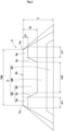
- FIG. 2 is a schematic view of the tread portion 2.
- the first rubber layer 3A includes first portions 3a each having a thickness t1 that is 5% to 25% of a tread thickness T and a second portion 3b having a thickness t2 that is 35% to 55% of the tread thickness T.
- each first portion 3a is disposed at a position that greatly affects low fuel consumption performance and the second portion 3b is disposed at a position that greatly affects grip performance, so that both grip performance and low fuel consumption performance, which have a trade-off relationship, can be achieved at high levels.
- the tire 1 of the present embodiment can achieve both grip performance and low fuel consumption performance.
- the first rubber layer 3A includes third portions 3c each disposed between the first portion 3a and the second portion 3b.
- the thickness of each third portion 3c of the first rubber layer 3A is gradually increased from the thickness t1 of the first portion 3a to the thickness t2 of the second portion 3b, for example. Change in stress between each first portion 3a and the second portion 3b is alleviated by such third portions 3c, and an object of improving durability can also be attained.
- FIG. 3 is a schematic view of the ground-contact surface 2s.
- a ground-contact length in the tire circumferential direction of a crown region around the tire equator C is large.
- the crown region has a large ground-contact area, and thus greatly affects grip performance such as braking performance on a wet road surface.
- a shoulder ground-contact length Ls at a position corresponding to 80% of the ground-contact width TW is preferably 65% to 95% of a crown ground-contact length Lc on the tire equator C.
- the shoulder ground-contact length Ls is not less than 65% of the crown ground-contact length Lc, the compressive strain of shoulder regions during load application can be alleviated, and heat generation can be inhibited in the shoulder regions which easily generate heat and greatly affect low fuel consumption performance, which serves to improve low fuel consumption performance.
- the shoulder ground-contact length Ls is not greater than 95% of the crown ground-contact length Lc, the large ground-contact area of the crown region can be ensured, which serves to improve grip performance.
- the first portions 3a of the present embodiment are located on both sides of the second portion 3b in the tire axial direction.
- the second portion 3b can be positioned around the tire equator C and the position thereof greatly affects grip performance
- the first portions 3a can be positioned on both sides of the second portion 3b and the positions thereof greatly affect low fuel consumption performance, so that both grip performance and low fuel consumption performance can be achieved.
- Each first portion 3a is preferably located outward of a position defining 35% to 45% of the ground-contact width TW from the tire equator C in the tire axial direction. Such first portions 3a can increase the contribution of the second rubber layer 3B in the shoulder regions which greatly affect low fuel consumption performance, so that low fuel consumption performance can be improved.
- a width w1 in the tire axial direction of each first portion 3a is preferably 5% to 20% of the ground-contact width TW.
- the width w1 of the first portion 3a is not less than 5% of the ground-contact width TW, the first portions 3a can be assuredly positioned at the shoulder regions which greatly affect low fuel consumption performance.
- the width w1 of the first portion 3a is not greater than 20% of the ground-contact width TW, the first rubber layer 3A in the second portion 3b can remain and excellent grip performance can be maintained, even if the first portion 3a disappears due to wear.
- the first portions 3a may extend outward of the tread ends Te in the tire axial direction.
- a width w2 in the tire axial direction of the second portion 3b is preferably 70% to 90% of the ground-contact width TW.
- the width w2 of the second portion 3b is not less than 70% of the ground-contact width TW, the contribution of the first rubber layer 3A can be increased in a crown region which greatly affects grip performance, so that grip performance can be improved.
- the width w2 of the second portion 3b is not greater than 90% of the ground-contact width TW, the contribution of the second rubber layer 3B can be increased in the shoulder regions which greatly affect low fuel consumption performance, so that low fuel consumption performance can be improved.
- the tread portion 2 has at least one circumferential groove 4 extending in the tire circumferential direction, and has four circumferential grooves 4 in the present embodiment.
- a groove depth d of each circumferential groove 4 is preferably 5.5 to 8.5 mm.
- the groove depth d of the circumferential groove 4 is not less than 5.5 mm, excellent drainage performance is exhibited during running on a wet road surface, so that wet performance can be improved.
- the tread thickness T of the tread portion 2 can be decreased, which serves to reduce the weight of the tread portion 2 to improve low fuel consumption performance.
- a groove bottom 4a of each circumferential groove 4 is, for example, located at the third rubber layer 3C.
- the tread thickness T can be decreased, so that low fuel consumption performance can be improved.
- the position of the groove bottom 4a of the circumferential groove 4 is not limited to such a mode, and the groove bottom 4a may be located at the second rubber layer 3B, for example. In this case, the tread portion 2 can maintain good grip performance even if the circumferential groove 4 is worn until it disappears.
- a loss tangent tan ⁇ 1 of the first rubber layer 3A at 30°C is preferably 0.20 to 0.25.
- the loss tangent tan ⁇ 1 of the first rubber layer 3A is not less than 0.20, such a first rubber layer 3A can exhibit good heat generation properties, so that both grip performance such as braking performance on a wet road surface, and on-snow performance can be achieved.
- the loss tangent tan ⁇ 1 of the first rubber layer 3A is not greater than 0.25, excessive heat generation is inhibited, which serves to improve low fuel consumption performance.
- the loss tangent is a value measured by the same method as the above-described complex elastic modulus. That is, the loss tangent is a value obtained by collecting, from each rubber layer 3, a sample having a length of 20 mm ⁇ a width of 4 mm ⁇ a thickness of 1 mm and measuring the sample by using a dynamic viscoelasticity measurement device (EPLEXOR series manufactured by NETZSCH-Gerätebau GmbH) in accordance with the standards of JIS-K6394 under the following conditions. The sample was collected so as to have a length in the tire circumferential direction, a width in the tire axial direction, and a thickness in the tire radial direction.
- a dynamic viscoelasticity measurement device EPLEXOR series manufactured by NETZSCH-Gerätebau GmbH
- a loss tangent tan62 of the second rubber layer 3B at 30°C is less than the loss tangent tan ⁇ 1 of the first rubber layer 3A.
- Such a second rubber layer 3B can further inhibit heat generation than first rubber layer 3A, so that low fuel consumption performance can be improved.
- the loss tangent tan ⁇ 2 of the second rubber layer 3B is preferably 60% to 80% of the loss tangent tan ⁇ 1 of the first rubber layer 3A.
- the loss tangent tan62 of the second rubber layer 3B is not less than 60% of the loss tangent tan ⁇ 1 of the first rubber layer 3A, good grip performance can be maintained even if the second rubber layer 3B serves as the ground-contact surface 2s due to wear.
- the loss tangent tan62 of the second rubber layer 3B is not greater than 80% of the loss tangent tan ⁇ 1 of the first rubber layer 3A, heat generation can be inhibited during load application, so that low fuel consumption performance can be improved.
- Tires having the basic structure shown in FIG. 1 were produced as test tires on the basis of specifications in Table 1. Low fuel consumption performance and grip performance were tested using the produced test tires, and combined performance represented by the total thereof was evaluated. Main common specifications and test methods are as follows.
- Each produced test tire was mounted to a rolling resistance testing machine, and a rolling resistance value was measured under the conditions that an air pressure was adjusted to be 250 kPa and a load of 8.09 kN was applied to the tire.
- the results are represented as indexes with the result of Comparative Example 1 being regarded as 100. A higher value indicates that the rolling resistance value is lower and the low fuel consumption performance is better.
- the produced test tires were mounted to the test vehicle.
- One test driver rode in the test vehicle, and a braking test on a wet road surface was performed.
- the braking distance was measured on a wet road surface in the same manner with the produced test tire in a 70% worn state.
- the results are represented as indexes with the result of Comparative Example 1 being regarded as 100. A higher value indicates that the braking distance is shorter and the grip performance is better.
- the present invention is as follows.
- a tire including a tread portion, wherein
- each first portion is located outward of a position defining 35% to 45% of a ground-contact width TW from a tire equator in the tire axial direction.
- a shoulder ground-contact length Ls at a position corresponding to 80% of the ground-contact width TW is 65% to 95% of a crown ground-contact length Lc on the tire equator.
Landscapes
- Engineering & Computer Science (AREA)
- Mechanical Engineering (AREA)
- Tires In General (AREA)
Abstract
Description
- The present invention relates to a tire including a tread portion.
- Conventionally, a tire including a tread portion composed of a plurality of rubber layers has been known.
Japanese Laid-Open Patent Publication No. 2017-210044 - However, in the tire of
Japanese Laid-Open Patent Publication No. 2017-210044 - The present invention has been made in view of the above circumstances, and a main object of the present invention is to provide a tire capable of achieving both grip performance and low fuel consumption performance.
- The present invention is directed to a tire including a tread portion, wherein the tread portion includes a first rubber layer forming a ground-contact surface, a second rubber layer located inward of the first rubber layer in a tire radial direction, and a third rubber layer located inward of the second rubber layer in the tire radial direction, a complex elastic modulus E* 1 of the first rubber layer at 30°C is not greater than 8.5 MPa, a complex elastic modulus E*2 of the second rubber layer at 30°C is 80% to 90% of the complex elastic modulus E* 1 of the first rubber layer, a complex elastic modulus E*3 of the third rubber layer at 30°C is 35% to 45% of the complex elastic modulus E* 1 of the first rubber layer, and the first rubber layer includes first portions each having a thickness t1 that is 5% to 25% of a tread thickness T and a second portion having a thickness t2 that is 35% to 55% of the tread thickness T.
- As a result of having the above-described configuration, the tire of the present invention can achieve both grip performance and low fuel consumption performance.
-
-
FIG. 1 is a sectional view of a tread portion of a tire according to one embodiment of the present invention; -
FIG. 2 is a schematic view of the tread portion; and -
FIG. 3 is a schematic view of a ground-contact surface. - Hereinafter, an embodiment of the present invention will be described in detail with reference to the drawings.
-
FIG. 1 is a tire meridional cross-sectional view of atread portion 2 of a tire 1 in a standardized state according to the present embodiment. As shown inFIG. 1 , the tire 1 of the present embodiment includes thetread portion 2. The tire 1 of the present embodiment is suitably used as a pneumatic tire to be mounted to a passenger car or the like. The tire 1 is not limited to a pneumatic tire for a passenger car, and is applicable as various tires such as a heavy-duty pneumatic tire, a motorcycle pneumatic tire, and an airless tire. - Here, in the case where the tire 1 is a pneumatic tire, the "standardized state" is a state where the tire 1 is mounted on a standardized rim and adjusted to a standardized internal pressure and no load is applied to the tire 1. Hereinafter, unless otherwise specified, dimensions and the like of components of the tire 1 are values measured in the standardized state.
- If there is a standard system including a standard on which the tire 1 is based, the "standardized rim" is a rim that is defined for each tire by the standard, and is, for example, the "standard rim" in the JATMA standard, the "Design Rim" in the TRA standard, or the "Measuring Rim" in the ETRTO standard. If there is no standard system including a standard on which the tire 1 is based, the "standardized rim" is a rim having the smallest rim diameter and having the smallest rim width, among rims to which the tire 1 can be fitted and which do not cause air leakage.
- If there is a standard system including a standard on which the tire 1 is based, the "standardized internal pressure" is an air pressure that is defined for each tire by each standard, and is the "maximum air pressure" in the JATMA standard, the maximum value indicated in the table "TIRE LOAD LIMITS AT VARIOUS COLD INFLATION PRESSURES" in the TRA standard, or the "INFLATION PRESSURE" in the ETRTO standard. If there is no standard system including a standard on which the tire 1 is based, the "standardized internal pressure" is an air pressure that is defined for each tire by the manufacturer or the like.
- The
tread portion 2 of the present embodiment has a ground-contact surface 2s extending between a pair of tread ends Te. Here, in the case where the tire 1 is a pneumatic tire, the pair of tread ends Te are outermost ground-contact positions in a tire axial direction when 70% of a standardized load is applied to the pneumatic tire in the standardized state and the pneumatic tire is brought into contact with a flat surface at a camber angle of 0°. The distance in the tire axial direction between the pair of tread ends Te is a ground-contact width TW. In addition, the center position in the tire axial direction between the pair of tread ends Te is a tire equator C. - If there is a standard system including a standard on which the tire 1 is based, the "standardized load" is a load that is defined for each tire by each standard, and is the "maximum load capacity" in the JATMA standard, the maximum value indicated in the table "TIRE LOAD LIMITS AT VARIOUS COLD INFLATION PRESSURES" in the TRA standard, or the "LOAD CAPACITY" in the ETRTO standard. If there is no standard system including a standard on which the tire 1 is based, the "standardized load" is a load that is defined for each tire by the manufacturer or the like.
- The
tread portion 2 of the present embodiment includes a plurality ofrubber layers 3. The plurality ofrubber layers 3 include afirst rubber layer 3A forming the ground-contact surface 2s, asecond rubber layer 3B located inward of thefirst rubber layer 3A in a tire radial direction, and athird rubber layer 3C located inward of thesecond rubber layer 3B in the tire radial direction. The properties of the plurality ofrubber layers 3 are made different, and thus such atread portion 2 serves to achieve both grip performance and low fuel consumption performance. - A complex elastic modulus E*1 of the
first rubber layer 3A at 30°C is preferably not greater than 8.5 MPa. Such afirst rubber layer 3A can exhibit good heat generation properties, so that grip performance such as braking performance on a wet road surface can be improved. In addition, thefirst rubber layer 3A also serves to attain an object of improving on-snow performance. From the viewpoint of steering stability on a dry road surface, the complex elastic modulus E* 1 of thefirst rubber layer 3A is preferably not less than 6.0 MPa. - Here, the complex elastic modulus is a value obtained by collecting, from each
rubber layer 3, a sample having a length of 20 mm × a width of 4 mm × a thickness of 1 mm and measuring the sample by using a dynamic viscoelasticity measurement device (EPLEXOR series manufactured by NETZSCH-Gerätebau GmbH) in accordance with the standards of JIS-K6394 under the following conditions. The sample was collected so as to have a length in a tire circumferential direction, a width in the tire axial direction, and a thickness in the tire radial direction. - Initial strain: 5%
- Dynamic strain: 1%
- Frequency: 10 Hz
- Deformation mode: stretch
- Measurement temperature: 30°C
- A complex elastic modulus E*2 of the
second rubber layer 3B at 30°C is preferably 80% to 90% of the complex elastic modulus E* 1 of thefirst rubber layer 3A. Such asecond rubber layer 3B can further inhibit heat generation than thefirst rubber layer 3A, so that low fuel consumption performance can be improved. - A complex elastic modulus E*3 of the
third rubber layer 3C at 30°C is preferably 35% to 45% of the complex elastic modulus E* 1 of thefirst rubber layer 3A. Such athird rubber layer 3C in an inner region in the tire radial direction where heat is easily stored can further inhibit heat generation than thefirst rubber layer 3A and thesecond rubber layer 3B, so that low fuel consumption performance can be improved. -
FIG. 2 is a schematic view of thetread portion 2. As shown inFIG. 1 andFIG. 2 , thefirst rubber layer 3A includesfirst portions 3a each having a thickness t1 that is 5% to 25% of a tread thickness T and asecond portion 3b having a thickness t2 that is 35% to 55% of the tread thickness T. - In such a
tread portion 2, eachfirst portion 3a is disposed at a position that greatly affects low fuel consumption performance and thesecond portion 3b is disposed at a position that greatly affects grip performance, so that both grip performance and low fuel consumption performance, which have a trade-off relationship, can be achieved at high levels. Thus, the tire 1 of the present embodiment can achieve both grip performance and low fuel consumption performance. - In a more preferable mode, the
first rubber layer 3A includesthird portions 3c each disposed between thefirst portion 3a and thesecond portion 3b. The thickness of eachthird portion 3c of thefirst rubber layer 3A is gradually increased from the thickness t1 of thefirst portion 3a to the thickness t2 of thesecond portion 3b, for example. Change in stress between eachfirst portion 3a and thesecond portion 3b is alleviated by suchthird portions 3c, and an object of improving durability can also be attained. -
FIG. 3 is a schematic view of the ground-contact surface 2s. As shown inFIG. 3 , in the ground-contact surface 2s of the present embodiment, a ground-contact length in the tire circumferential direction of a crown region around the tire equator C is large. In such a ground-contact surface 2s, the crown region has a large ground-contact area, and thus greatly affects grip performance such as braking performance on a wet road surface. - In the ground-
contact surface 2s, a shoulder ground-contact length Ls at a position corresponding to 80% of the ground-contact width TW is preferably 65% to 95% of a crown ground-contact length Lc on the tire equator C. When the shoulder ground-contact length Ls is not less than 65% of the crown ground-contact length Lc, the compressive strain of shoulder regions during load application can be alleviated, and heat generation can be inhibited in the shoulder regions which easily generate heat and greatly affect low fuel consumption performance, which serves to improve low fuel consumption performance. When the shoulder ground-contact length Ls is not greater than 95% of the crown ground-contact length Lc, the large ground-contact area of the crown region can be ensured, which serves to improve grip performance. - As shown in
FIG. 1 andFIG. 2 , thefirst portions 3a of the present embodiment are located on both sides of thesecond portion 3b in the tire axial direction. In such atread portion 2, thesecond portion 3b can be positioned around the tire equator C and the position thereof greatly affects grip performance, and thefirst portions 3a can be positioned on both sides of thesecond portion 3b and the positions thereof greatly affect low fuel consumption performance, so that both grip performance and low fuel consumption performance can be achieved. - Each
first portion 3a is preferably located outward of a position defining 35% to 45% of the ground-contact width TW from the tire equator C in the tire axial direction. Suchfirst portions 3a can increase the contribution of thesecond rubber layer 3B in the shoulder regions which greatly affect low fuel consumption performance, so that low fuel consumption performance can be improved. - A width w1 in the tire axial direction of each
first portion 3a is preferably 5% to 20% of the ground-contact width TW. When the width w1 of thefirst portion 3a is not less than 5% of the ground-contact width TW, thefirst portions 3a can be assuredly positioned at the shoulder regions which greatly affect low fuel consumption performance. When the width w1 of thefirst portion 3a is not greater than 20% of the ground-contact width TW, thefirst rubber layer 3A in thesecond portion 3b can remain and excellent grip performance can be maintained, even if thefirst portion 3a disappears due to wear. For example, thefirst portions 3a may extend outward of the tread ends Te in the tire axial direction. - A width w2 in the tire axial direction of the
second portion 3b is preferably 70% to 90% of the ground-contact width TW. When the width w2 of thesecond portion 3b is not less than 70% of the ground-contact width TW, the contribution of thefirst rubber layer 3A can be increased in a crown region which greatly affects grip performance, so that grip performance can be improved. When the width w2 of thesecond portion 3b is not greater than 90% of the ground-contact width TW, the contribution of thesecond rubber layer 3B can be increased in the shoulder regions which greatly affect low fuel consumption performance, so that low fuel consumption performance can be improved. - As shown in
FIG. 1 andFIG. 3 , thetread portion 2 has at least onecircumferential groove 4 extending in the tire circumferential direction, and has fourcircumferential grooves 4 in the present embodiment. A groove depth d of eachcircumferential groove 4 is preferably 5.5 to 8.5 mm. When the groove depth d of thecircumferential groove 4 is not less than 5.5 mm, excellent drainage performance is exhibited during running on a wet road surface, so that wet performance can be improved. When the groove depth d of thecircumferential groove 4 is not greater than 8.5 mm, the tread thickness T of thetread portion 2 can be decreased, which serves to reduce the weight of thetread portion 2 to improve low fuel consumption performance. - A
groove bottom 4a of eachcircumferential groove 4 is, for example, located at thethird rubber layer 3C. In such atread portion 2, the tread thickness T can be decreased, so that low fuel consumption performance can be improved. The position of thegroove bottom 4a of thecircumferential groove 4 is not limited to such a mode, and thegroove bottom 4a may be located at thesecond rubber layer 3B, for example. In this case, thetread portion 2 can maintain good grip performance even if thecircumferential groove 4 is worn until it disappears. - A loss tangent tanδ1 of the
first rubber layer 3A at 30°C is preferably 0.20 to 0.25. When the loss tangent tanδ1 of thefirst rubber layer 3A is not less than 0.20, such afirst rubber layer 3A can exhibit good heat generation properties, so that both grip performance such as braking performance on a wet road surface, and on-snow performance can be achieved. When the loss tangent tanδ1 of thefirst rubber layer 3A is not greater than 0.25, excessive heat generation is inhibited, which serves to improve low fuel consumption performance. - Here, the loss tangent is a value measured by the same method as the above-described complex elastic modulus. That is, the loss tangent is a value obtained by collecting, from each
rubber layer 3, a sample having a length of 20 mm × a width of 4 mm × a thickness of 1 mm and measuring the sample by using a dynamic viscoelasticity measurement device (EPLEXOR series manufactured by NETZSCH-Gerätebau GmbH) in accordance with the standards of JIS-K6394 under the following conditions. The sample was collected so as to have a length in the tire circumferential direction, a width in the tire axial direction, and a thickness in the tire radial direction. - Initial strain: 5%
- Dynamic strain: 1%
- Frequency: 10 Hz
- Deformation mode: stretch
- Measurement temperature: 30°C
- In the present embodiment, a loss tangent tan62 of the
second rubber layer 3B at 30°C is less than the loss tangent tanδ1 of thefirst rubber layer 3A. Such asecond rubber layer 3B can further inhibit heat generation thanfirst rubber layer 3A, so that low fuel consumption performance can be improved. - The loss tangent tanδ2 of the
second rubber layer 3B is preferably 60% to 80% of the loss tangent tanδ1 of thefirst rubber layer 3A. When the loss tangent tan62 of thesecond rubber layer 3B is not less than 60% of the loss tangent tanδ1 of thefirst rubber layer 3A, good grip performance can be maintained even if thesecond rubber layer 3B serves as the ground-contact surface 2s due to wear. When the loss tangent tan62 of thesecond rubber layer 3B is not greater than 80% of the loss tangent tanδ1 of thefirst rubber layer 3A, heat generation can be inhibited during load application, so that low fuel consumption performance can be improved. - Although the particularly preferred embodiment of the present invention has been described in detail above, the present invention is not limited to the above-described embodiment, and various modifications can be made to implement the present invention.
- Tires having the basic structure shown in
FIG. 1 were produced as test tires on the basis of specifications in Table 1. Low fuel consumption performance and grip performance were tested using the produced test tires, and combined performance represented by the total thereof was evaluated. Main common specifications and test methods are as follows. -
- Tire size: 255/50R20 109V XL
- Rim size: 20×8.0J
- Test vehicle: large-sized SUV
- Each produced test tire was mounted to a rolling resistance testing machine, and a rolling resistance value was measured under the conditions that an air pressure was adjusted to be 250 kPa and a load of 8.09 kN was applied to the tire. The results are represented as indexes with the result of Comparative Example 1 being regarded as 100. A higher value indicates that the rolling resistance value is lower and the low fuel consumption performance is better.
- The produced test tires were mounted to the test vehicle. One test driver rode in the test vehicle, and a braking test on a wet road surface was performed. In addition, the braking distance was measured on a wet road surface in the same manner with the produced test tire in a 70% worn state. The results are represented as indexes with the result of Comparative Example 1 being regarded as 100. A higher value indicates that the braking distance is shorter and the grip performance is better.
- The results of the tests are indicated in Table 1.
[Table 1] Comp. Ex. 1 Comp. Ex. 2 Comp. Ex. 3 Comp. Ex. 4 Comp. Ex. 5 Ex. 1 Ex. 2 Ex. 3 Complex elastic modulus E*1 of first rubber layer (MPa) 8.5 8.5 8.5 8.5 9.5 8.5 8.5 8.5 Complex elastic modulus E*2 of second rubber layer / complex elastic modulus E*1 of first rubber layer (%) 90 90 90 90 100 90 90 90 Complex elastic modulus E*3 of third rubber layer / complex elastic modulus E*1 of first rubber layer (%) 40 40 40 40 30 40 40 40 Loss tangent tanδ1 of first rubber layer 0.20 0.20 0.20 0.20 0.27 0.20 0.20 0.20 Thickness t1 of first portion / tread thickness T (%) 15 45 0 5 5 5 25 5 Thickness t2 of second portion / tread thickness T (%) 15 45 45 30 45 45 45 35 Low fuel consumption performance (index) 100 98 100 99 98 100 99 99 Grip performance (index) 100 100 95 100 100 100 100 100 Grip performance in 70% worn state (index) 75 90 90 75 90 93 90 90 Combined performance (index) 275 288 285 274 288 293 289 289 - As a result of the tests, it is confirmed that the tire of each Example has better combined performance evaluated by the total of low fuel consumption performance, grip performance, and grip performance in a 70% wear state than those of the Comparative Examples, and achieves both grip performance and low fuel consumption performance.
- The present invention is as follows.
- A tire including a tread portion, wherein
- the tread portion includes a first rubber layer forming a ground-contact surface, a second rubber layer located inward of the first rubber layer in a tire radial direction, and a third rubber layer located inward of the second rubber layer in the tire radial direction,
- a complex elastic modulus E* 1 of the first rubber layer at 30°C is not greater than 8.5 MPa,
- a complex elastic modulus E*2 of the second rubber layer at 30°C is 80% to 90% of the complex elastic modulus E* 1 of the first rubber layer,
- a complex elastic modulus E*3 of the third rubber layer at 30°C is 35% to 45% of the complex elastic modulus E* 1 of the first rubber layer, and
- the first rubber layer includes first portions each having a thickness t1 that is 5% to 25% of a tread thickness T and a second portion having a thickness t2 that is 35% to 55% of the tread thickness T.
- The tire according to Present Invention 1, wherein the first portions are located on both sides of the second portion in a tire axial direction.
- The tire according to
Present Invention 1 or 2, wherein each first portion is located outward of a position defining 35% to 45% of a ground-contact width TW from a tire equator in the tire axial direction. - The tire according to any one of Present Inventions 1 to 3, wherein a width w2 in the tire axial direction of the second portion is 70% to 90% of the ground-contact width TW.
- The tire according to any one of Present Inventions 1 to 4, wherein
in the ground-contact surface, a shoulder ground-contact length Ls at a position corresponding to 80% of the ground-contact width TW is 65% to 95% of a crown ground-contact length Lc on the tire equator. - The tire according to any one of Present Inventions 1 to 5, wherein
- the tread portion includes at least one circumferential groove extending in a tire circumferential direction, and
- a groove depth of the circumferential groove is 5.5 to 8.5 mm.
- The tire according to Present Invention 6, wherein a groove bottom of the circumferential groove is located at the third rubber layer.
- The tire according to any one of Present Inventions 1 to 7, wherein a loss tangent tanδ1 of the first rubber layer at 30°C is 0.20 to 0.25.
- The tire according to Present Invention 8, wherein a loss tangent tan62 of the second rubber layer at 30°C is less than the loss tangent tanδ1 of the first rubber layer.
- The tire according to Present Invention 9, wherein the loss tangent tanδ2 of the second rubber layer is 60% to 80% of the loss tangent tanδ1 of the first rubber layer.
Claims (10)
- A tire (1) comprising a tread portion (2), whereinthe tread portion (2) includes a first rubber layer (3A) forming a ground-contact surface (2s), a second rubber layer (3B) located inward of the first rubber layer (3A) in a tire radial direction, and a third rubber layer (3C) located inward of the second rubber layer (3B) in the tire radial direction,a complex elastic modulus (E* 1) of the first rubber layer (3A) at 30°C is not greater than 8.5 MPa,a complex elastic modulus (E*2) of the second rubber layer (3B) at 30°C is 80% to 90% of the complex elastic modulus (E* 1) of the first rubber layer (3A),a complex elastic modulus (E*3) of the third rubber layer (3C) at 30°C is 35% to 45% of the complex elastic modulus (E* 1) of the first rubber layer (3A), andthe first rubber layer (3A) includes first portions (3a) each having a thickness (t1) that is 5% to 25% of a tread thickness (T) and a second portion (3b) having a thickness (t2) that is 35% to 55% of the tread thickness (T).
- The tire (1) according to claim 1, wherein the first portions (3a) are located on both sides of the second portion (3b) in a tire axial direction.
- The tire (1) according to claim 1 or 2, wherein each first portion (3a) is located outward of a position defining 35% to 45% of a ground-contact width (TW) from a tire equator (C) in the tire axial direction.
- The tire (1) according to any one of claims 1 to 3, wherein a width w2 in the tire axial direction of the second portion (3b) is 70% to 90% of the ground-contact width (TW).
- The tire (1) according to any one of claims 1 to 4, wherein
in the ground-contact surface (2s), a shoulder ground-contact length (Ls) at a position corresponding to 80% of the ground-contact width (TW) is 65% to 95% of a crown ground-contact length (Lc) on the tire equator (C). - The tire (1) according to any one of claims 1 to 5, whereinthe tread portion (2) includes at least one circumferential groove (4) extending in a tire circumferential direction, anda groove depth (d) of the circumferential groove (4) is 5.5 to 8.5 mm.
- The tire (1) according to claim 6, wherein a groove bottom (4a) of the circumferential groove (4) is located at the third rubber layer (3C).
- The tire (1) according to any one of claims 1 to 7, wherein a loss tangent (tanδ1) of the first rubber layer (3A) at 30°C is 0.20 to 0.25.
- The tire (1) according to claim 8, wherein a loss tangent (tanδ2) of the second rubber layer (3B) at 30°C is less than the loss tangent (tanδ1) of the first rubber layer (3A).
- The tire (1) according to claim 9, wherein the loss tangent (tanδ2) of the second rubber layer (3B) is 60% to 80% of the loss tangent (tanδ1) of the first rubber layer (3A).
Applications Claiming Priority (1)
| Application Number | Priority Date | Filing Date | Title |
|---|---|---|---|
| JP2023135713A JP2025030429A (en) | 2023-08-23 | 2023-08-23 | tire |
Publications (1)
| Publication Number | Publication Date |
|---|---|
| EP4512634A1 true EP4512634A1 (en) | 2025-02-26 |
Family
ID=92172091
Family Applications (1)
| Application Number | Title | Priority Date | Filing Date |
|---|---|---|---|
| EP24192038.8A Pending EP4512634A1 (en) | 2023-08-23 | 2024-07-31 | Tire |
Country Status (2)
| Country | Link |
|---|---|
| EP (1) | EP4512634A1 (en) |
| JP (1) | JP2025030429A (en) |
Citations (4)
| Publication number | Priority date | Publication date | Assignee | Title |
|---|---|---|---|---|
| JP4410505B2 (en) * | 2003-07-15 | 2010-02-03 | 住友ゴム工業株式会社 | Heavy duty pneumatic tire |
| JP2017210044A (en) | 2016-05-24 | 2017-11-30 | 住友ゴム工業株式会社 | Pneumatic tire |
| US20220063334A1 (en) * | 2020-08-27 | 2022-03-03 | Sumitomo Rubber Industries, Ltd. | Heavy duty tire |
| US20220203769A1 (en) * | 2020-12-28 | 2022-06-30 | Sumitomo Rubber Industries, Ltd. | Tire |
-
2023
- 2023-08-23 JP JP2023135713A patent/JP2025030429A/en active Pending
-
2024
- 2024-07-31 EP EP24192038.8A patent/EP4512634A1/en active Pending
Patent Citations (4)
| Publication number | Priority date | Publication date | Assignee | Title |
|---|---|---|---|---|
| JP4410505B2 (en) * | 2003-07-15 | 2010-02-03 | 住友ゴム工業株式会社 | Heavy duty pneumatic tire |
| JP2017210044A (en) | 2016-05-24 | 2017-11-30 | 住友ゴム工業株式会社 | Pneumatic tire |
| US20220063334A1 (en) * | 2020-08-27 | 2022-03-03 | Sumitomo Rubber Industries, Ltd. | Heavy duty tire |
| US20220203769A1 (en) * | 2020-12-28 | 2022-06-30 | Sumitomo Rubber Industries, Ltd. | Tire |
Also Published As
| Publication number | Publication date |
|---|---|
| JP2025030429A (en) | 2025-03-07 |
Similar Documents
| Publication | Publication Date | Title |
|---|---|---|
| EP2628612B1 (en) | Pneumatic tire | |
| US9415637B2 (en) | Pneumatic tire | |
| JP4303051B2 (en) | Pneumatic tire | |
| EP3753752A1 (en) | Pneumatic tire | |
| EP3530487B1 (en) | Two-wheeled vehicle tyre | |
| EP3059100B1 (en) | Pneumatic tire | |
| EP3069899A1 (en) | Pneumatic tire | |
| EP3936660B1 (en) | Tire | |
| CN106715158B (en) | run-flat tires | |
| EP3967520B1 (en) | Tire having tread grooves | |
| EP4173845B1 (en) | Tire | |
| EP3967521B1 (en) | Tire having tread grooves and method for configuring groove depths | |
| EP4070968B1 (en) | Motorcycle tyre | |
| EP3838620B1 (en) | Motorcycle tire | |
| EP3552843B1 (en) | Two-wheeled vehicle tyre | |
| EP3943660B1 (en) | Tire | |
| EP3689644B1 (en) | Tire | |
| EP4678421A1 (en) | Pneumatic tire | |
| EP4242013B1 (en) | Pneumatic tire | |
| JP4566788B2 (en) | Pneumatic tires for passenger cars | |
| EP4635751A1 (en) | Pneumatic tire | |
| EP3858641B1 (en) | Pneumatic tire | |
| JP2025030429A (en) | tire | |
| JP2025162444A (en) | pneumatic tires |
Legal Events
| Date | Code | Title | Description |
|---|---|---|---|
| PUAI | Public reference made under article 153(3) epc to a published international application that has entered the european phase |
Free format text: ORIGINAL CODE: 0009012 |
|
| STAA | Information on the status of an ep patent application or granted ep patent |
Free format text: STATUS: THE APPLICATION HAS BEEN PUBLISHED |
|
| AK | Designated contracting states |
Kind code of ref document: A1 Designated state(s): AL AT BE BG CH CY CZ DE DK EE ES FI FR GB GR HR HU IE IS IT LI LT LU LV MC ME MK MT NL NO PL PT RO RS SE SI SK SM TR |
|
| STAA | Information on the status of an ep patent application or granted ep patent |
Free format text: STATUS: REQUEST FOR EXAMINATION WAS MADE |
|
| P01 | Opt-out of the competence of the unified patent court (upc) registered |
Free format text: CASE NUMBER: APP_12456/2025 Effective date: 20250313 |
|
| 17P | Request for examination filed |
Effective date: 20250331 |
|
| GRAP | Despatch of communication of intention to grant a patent |
Free format text: ORIGINAL CODE: EPIDOSNIGR1 |
|
| STAA | Information on the status of an ep patent application or granted ep patent |
Free format text: STATUS: GRANT OF PATENT IS INTENDED |