EP3069899A1 - Pneumatic tire - Google Patents
Pneumatic tire Download PDFInfo
- Publication number
- EP3069899A1 EP3069899A1 EP16158366.1A EP16158366A EP3069899A1 EP 3069899 A1 EP3069899 A1 EP 3069899A1 EP 16158366 A EP16158366 A EP 16158366A EP 3069899 A1 EP3069899 A1 EP 3069899A1
- Authority
- EP
- European Patent Office
- Prior art keywords
- tire
- tread
- pattern
- width
- land
- Prior art date
- Legal status (The legal status is an assumption and is not a legal conclusion. Google has not performed a legal analysis and makes no representation as to the accuracy of the status listed.)
- Granted
Links
- 239000011324 bead Substances 0.000 claims abstract description 41
- 238000005096 rolling process Methods 0.000 description 33
- 238000012360 testing method Methods 0.000 description 23
- 238000005259 measurement Methods 0.000 description 15
- 239000000446 fuel Substances 0.000 description 11
- 230000000694 effects Effects 0.000 description 5
- 238000005452 bending Methods 0.000 description 3
- 238000011161 development Methods 0.000 description 3
- 238000006073 displacement reaction Methods 0.000 description 3
- 239000000853 adhesive Substances 0.000 description 2
- 230000007423 decrease Effects 0.000 description 2
- 230000003247 decreasing effect Effects 0.000 description 2
- 238000005299 abrasion Methods 0.000 description 1
- 238000013459 approach Methods 0.000 description 1
- 238000010586 diagram Methods 0.000 description 1
- 238000002474 experimental method Methods 0.000 description 1
- 230000017525 heat dissipation Effects 0.000 description 1
- 238000005338 heat storage Methods 0.000 description 1
- 238000011056 performance test Methods 0.000 description 1
- 230000003014 reinforcing effect Effects 0.000 description 1
- 238000013112 stability test Methods 0.000 description 1
Images


Classifications
-
- B—PERFORMING OPERATIONS; TRANSPORTING
- B60—VEHICLES IN GENERAL
- B60C—VEHICLE TYRES; TYRE INFLATION; TYRE CHANGING; CONNECTING VALVES TO INFLATABLE ELASTIC BODIES IN GENERAL; DEVICES OR ARRANGEMENTS RELATED TO TYRES
- B60C3/00—Tyres characterised by the transverse section
- B60C3/04—Tyres characterised by the transverse section characterised by the relative dimensions of the section, e.g. low profile
-
- B—PERFORMING OPERATIONS; TRANSPORTING
- B60—VEHICLES IN GENERAL
- B60C—VEHICLE TYRES; TYRE INFLATION; TYRE CHANGING; CONNECTING VALVES TO INFLATABLE ELASTIC BODIES IN GENERAL; DEVICES OR ARRANGEMENTS RELATED TO TYRES
- B60C11/00—Tyre tread bands; Tread patterns; Anti-skid inserts
- B60C11/03—Tread patterns
- B60C11/0304—Asymmetric patterns
-
- B—PERFORMING OPERATIONS; TRANSPORTING
- B60—VEHICLES IN GENERAL
- B60C—VEHICLE TYRES; TYRE INFLATION; TYRE CHANGING; CONNECTING VALVES TO INFLATABLE ELASTIC BODIES IN GENERAL; DEVICES OR ARRANGEMENTS RELATED TO TYRES
- B60C11/00—Tyre tread bands; Tread patterns; Anti-skid inserts
- B60C11/03—Tread patterns
- B60C11/0306—Patterns comprising block rows or discontinuous ribs
-
- B—PERFORMING OPERATIONS; TRANSPORTING
- B60—VEHICLES IN GENERAL
- B60C—VEHICLE TYRES; TYRE INFLATION; TYRE CHANGING; CONNECTING VALVES TO INFLATABLE ELASTIC BODIES IN GENERAL; DEVICES OR ARRANGEMENTS RELATED TO TYRES
- B60C11/00—Tyre tread bands; Tread patterns; Anti-skid inserts
- B60C11/03—Tread patterns
- B60C11/0327—Tread patterns characterised by special properties of the tread pattern
- B60C11/033—Tread patterns characterised by special properties of the tread pattern by the void or net-to-gross ratios of the patterns
-
- B—PERFORMING OPERATIONS; TRANSPORTING
- B60—VEHICLES IN GENERAL
- B60C—VEHICLE TYRES; TYRE INFLATION; TYRE CHANGING; CONNECTING VALVES TO INFLATABLE ELASTIC BODIES IN GENERAL; DEVICES OR ARRANGEMENTS RELATED TO TYRES
- B60C11/00—Tyre tread bands; Tread patterns; Anti-skid inserts
- B60C11/03—Tread patterns
- B60C11/0327—Tread patterns characterised by special properties of the tread pattern
- B60C11/0332—Tread patterns characterised by special properties of the tread pattern by the footprint-ground contacting area of the tyre tread
-
- B—PERFORMING OPERATIONS; TRANSPORTING
- B60—VEHICLES IN GENERAL
- B60C—VEHICLE TYRES; TYRE INFLATION; TYRE CHANGING; CONNECTING VALVES TO INFLATABLE ELASTIC BODIES IN GENERAL; DEVICES OR ARRANGEMENTS RELATED TO TYRES
- B60C11/00—Tyre tread bands; Tread patterns; Anti-skid inserts
- B60C11/0008—Tyre tread bands; Tread patterns; Anti-skid inserts characterised by the tread rubber
- B60C2011/0016—Physical properties or dimensions
- B60C2011/0025—Modulus or tan delta
-
- B—PERFORMING OPERATIONS; TRANSPORTING
- B60—VEHICLES IN GENERAL
- B60C—VEHICLE TYRES; TYRE INFLATION; TYRE CHANGING; CONNECTING VALVES TO INFLATABLE ELASTIC BODIES IN GENERAL; DEVICES OR ARRANGEMENTS RELATED TO TYRES
- B60C11/00—Tyre tread bands; Tread patterns; Anti-skid inserts
- B60C11/03—Tread patterns
- B60C2011/0337—Tread patterns characterised by particular design features of the pattern
- B60C2011/0386—Continuous ribs
- B60C2011/0388—Continuous ribs provided at the equatorial plane
Definitions
- the present invention relates to a pneumatic tire capable of improving fuel consumption performance while ensuring wet performance as well as steering stability.
- the present inventors who had conducted studies were able to find the following.
- the tread width is also decreased accordingly.
- the volume of the tread rubber is reduced.
- the energy loss caused by the tread rubber is reduced, and the weight of the tire is also lowered.
- a tire exposed area appearing downwardly from a bumper edge of the vehicle is reduced according to the reduced tire section width. This makes it possible to reduce the air resistance of the tire.
- the present invention has an object to provide a pneumatic tire, in particular, a narrow-width and large bead diameter tire capable of improving fuel consumption performance while ensuring wet performance as well as steering stability by basically employing a tread pattern including three rib-shaped land portions and a land ratio of not less than 85%.
- a pneumatic tire comprises a carcass extending between bead cores of bead portions through a tread portion and a pair of sidewall portions.
- a tire section width Wt (unit: mm) in relation to a bead diameter Db (unit: inch) satisfies the following equations (1) and (2): Wt ⁇ ⁇ 07257 ⁇ Db 2 + 42.763 ⁇ Db ⁇ 339.67 Wt ⁇ ⁇ 0.7257 ⁇ Db 2 + 48.568 ⁇ Db ⁇ 552.33
- the tread portion comprises a tread pattern comprising three rib-shaped land portions separated by two longitudinal grooves, and a land ratio of the tread pattern is not less than 85%.
- the tread pattern may have lateral pattern rigidity in an axial direction of the tire in a range of from 2.8 to 3.2 kg/mm/mm.
- the tread pattern may have longitudinal pattern rigidity in a circumferential direction of the tire in a range of not less than 4.1 kg/mm/mm.
- the tread portion may comprise a tread rubber comprising a loss modulus E" of not more than 0.06 kg/mm 2 and a loss compliance Ls of not more than 0.28 mm 2 /kg.
- the three rib-shaped land portions may comprise an outboard shoulder land portion having an axial width WSo, an inboard shoulder land portion having an axial width WSi and a central land portion having an axial width WC arranged therebetween, a ratio WSo/WC of the axial width WSo of the outboard shoulder land portion to the axial width WC of the central land portion may be in a range of from 0.95 to 1.32, and a ratio WSi/WC of the axial width WSi of the inboard shoulder land portion to the axial width WC of the central land portion may be in a range of from 1.35 to 1.60.
- the loss modulus E" and the loss compliance Ls are values measured using a viscoelastic spectrometer according to provision of JIS-K 6394 under a condition of initial strain of 10%, amplitude of 2%, frequency of 10 Hz, a tensile strain mode and temperature of 30 degrees C.
- the pneumatic tire according to the present invention is configured as a tire having a narrow width and a large bead diameter satisfying the above mentioned equations (1) and (2). Therefore reduction of energy loss in the tread portion and the sidewall portion, reduction of tire weight, and reduction of air resistance may be achieved, thereby improving fuel consumption. While, since the tire having a narrow width and a large bead diameter has a narrow tread width, the steering stability may be deteriorated.
- the tread portion employs the tread pattern including three rib-shaped land portions and the land ratio of not less than 85%.
- the tire having a narrow width and a large bead diameter may deliver better draining performance as compared with conventional tires due to its narrow tread width.
- the tire according to the invention may employ a high land ratio, i.e., the land ratio of not less than 85%, while ensuring wet grip performance on the same levels with conventional tires.
- the tread pattern consisting of three rib-shaped land portions may have a higher lateral rigidity than the tread pattern consisting of four rib-shaped land portions, when they have the same tread width.
- the tire according to the present invention may increase cornering force while ensuring wet grip performance on the same levels with conventional tires and offering low fuel consumption, by employing the tread pattern having three rib-shaped land portions and a land ratio of not less than 85%. That is, the tire in accordance with the present invention may offer an excellent low fuel consumption performance while ensuring the wet performance as well as the steering stability.
- the pneumatic tire 1 in accordance with the present embodiment includes a carcass 6 extending between bead cores 5 of bead portions 4 through a tread portion 2 and a pair of sidewall portions 3.
- the tire further includes a belt layer 7 disposed radially outward of the carcass 6 in the tread portion 2, and a reinforcing band layer 9 disposed radially outward of the belt layer 7.
- the carcass 6 includes one carcass ply 6A of carcass cords oriented as an angle of 75 to 90 degrees with respect to the tire equatorial plane Co.
- the carcass ply 6A for example, includes a toroidal main body 6a extending between the bead cores 5 and a pair of turn-up portions 6b each turned up around each bead core 5 from the axially inside to the outside of the tire.
- a radially tapering bead apex rubber 8 which extends from the bead core 5 is disposed between the main portion 6a and the turn-up portions 6b.
- the belt layer 7, for example, includes two belt plies 7A and 7B of belt cords oriented at an angle of from 10 to 35 degrees with respect to the tire equatorial plane Co.
- the belt plies 7A and 7B are overlapped one another so that belt cords of each ply intersect.
- the tread portion 2 may be enhanced by hoop effect of the belt layer 7 having high stiffness.
- the band layer 9A for example, includes a spiral band ply 9A of a band cord formed by being wound spirally at an angle of not more than 5 degrees with respect to the tire equatorial plane Co.
- the band layer 9 covers the substantially entire belt layer so as to restrain the movement of the belt layer 7. Accordingly, growth of the tire outer diameter during high speed traveling, in particular growth of shoulder portion can be prevented.
- the band layer 9 is configured to have an axial width greater than that of the belt layer 7.
- the pneumatic tire 1 is configured as a narrow width and a large bead diameter tire in which the tire section width Wt (unit: mm) in relation to the bead diameter Db (unit: inch) satisfies the following equations (1) and (2), Wt ⁇ ⁇ 0.7257 ⁇ Db 2 + 42.763 ⁇ Db ⁇ 339.67 Wt ⁇ ⁇ 0.7257 ⁇ Db 2 + 48.568 ⁇ Db ⁇ 552.33
- the region Y1 that satisfies the equations (1) and (2) is outside the scope of the conventional tires shown in the plots. Furthermore, the region Y1 exists on the location where the relationship Ka identified by the equation (A) is moved parallel to a direction to decrease the tire section width Wt as well as to enlarge the bead diameter Db. That is, the tire satisfying the equations (1) and (2) is configured so as to have a narrow tire section width Wt and an enlarged bead diameter Db as compared with conventional tires having the same tire outer diameter.
- Such a tire with a narrow tire section width may provide a narrow tread width which offers less tread rubber volume accordingly. Therefore energy loss due to the tread rubber is relatively less, and the tire mass is also reduced. Furthermore, when a vehicle is viewed from its front, a tire exposed area appearing downwardly from a bumper edge is reduced according to the reduced tire section width. This makes it possible to reduce the air resistance of the tire.
- the tire has an enlarged bead diameter as compared with conventional tires having the same tire outer diameter, a sidewall region, which tends to deform largely during traveling, becomes narrow. As a result, a reduction in energy loss by the sidewall portion 3 as well as the weight of the tire can be achieved.
- the tire having a narrow width and a large bead diameter may improve the fuel efficiency through a reduction in energy loss by the tread portion 2 and the sidewall portions 3, a reduction in tire mass, and the reduction of air resistance.
- the pneumatic tire 1 has a tire outer diameter Dt (Unit: mm) satisfying the following equations (3) and (4): Dt ⁇ 59.078 ⁇ Wt 0.498 and Dt ⁇ 59.078 ⁇ Wt 0.467
- the region Y2 that satisfies the equations (3) and (4) exists on the location where the relationship Kb identified by the equation (B) is moved parallel to a direction to enlarge the tire outer diameter Dt. That is, the tire satisfying the equations (3) and (4) has a narrow width, a large bead diameter and a large tire outer diameter Dt.
- the tire T1 with a relatively large outer diameter Dt is small in amount of bending deformation of the ground contacting portion in the circumferential direction of the tire as compared with the tire T2 with a relatively small outer diameter. Accordingly, the tire is small in energy loss and has advantageous effect of low rolling resistance. Therefore, when the tire does not satisfy the equation (4), low rolling resistance may not be expected. On the other hand, when the tire does not satisfy the equation (3), it may be necessary to be inflated with a high internal pressure to ensure necessary load capacity, and therefore ride comfort and road noise performance may be deteriorated.
- the tread portion 2 of the pneumatic tire 1 includes a tread pattern consisting of three rib-shaped land portions 11 separated by two longitudinal grooves 10.
- the three rib-shaped land portions 11 include a central land portion 11C disposed between the main grooves 10 and 10, and a pair of shoulder land portions 11S each disposed axially outward of each main groove 10.
- the main grooves 10 and 10 are arranged on both sides of the tire equator C in a symmetrical manner. Accordingly, the axial width WS1 of one of the shoulder land portions 11S is the same as the axial width WS2 of the other one of the shoulder land portions 11S, for example.
- the tread portion 2 is provided with only two main grooves 10 as a circumferentially and continuously extending groove which includes a sipe having a width of not more than 0.5 mm so as to close the width when coming into contact with the ground.
- Each rib-shaped land portion 11 is not provided with a lateral groove that extends across perfectly the land portion 11 to form a plurality of blocks. However, it is allowed to provide a sipe that extends across perfectly the land portion 11. Accordingly, each rib-shaped land portion 11 is formed as a rib that extends substantially continuously in the circumferential direction of the tire.
- the central land portion 11C is provided with a plurality of central sipes 12C extending across the central land portion 11C.
- Each shoulder land portion 11S is provided with a plurality of lug grooves 13S each extending axially inwardly from the tread edge Te and having an axially inner end E terminating within the shoulder land portion 11S and a plurality of first sipes 12S 1 each extending from each inner end E of each lug groove 13S, and at least one second sipe 12S 2 arranged between a pair of circumferentially adjacent lug grooves 13S.
- each second shoulder sipe 12S 2 has at least one end, preferably both ends that terminate within the shoulder land portion 11S.
- the tread pattern has a land ratio in a range of not less than 85% by adjusting widths of the main grooves 10 and lengths, widths and the number of the lug grooves 13S, for example.
- the land ratio is defined as a ratio Mb/Ma of a total area Mb of ground contact surface of the land portions to a tread gross surface area Ma obtained by adding the total ground contact surface of the land portions to the total area of the grooves.
- the tire having a narrow width and a large bead diameter may deliver better draining performance as compared with conventional tires due to its narrow tread width.
- the tire according to the present embodiment may employ a high land ratio, i.e., the land ratio of not less than 85%, while ensuring wet grip performance on the same levels with conventional tires.
- the tread pattern consisting of three rib-shaped land portions 11 may have a higher lateral rigidity and generate a larger cornering force than the tread pattern consisting of four rib-shaped land portions 11 (hereinafter, it may be referred to as a four-rib pattern P4), when they have the same specification including the tread width except for tread pattern only.
- FIG. 6 illustrates a graph showing the relationship among a land ratio, lateral pattern rigidity and cornering power index (Cp/W) of the respective three-rib pattern P3 and the four-rib tread pattern P4.
- the cornering power index (Cp/W) is a dimensionless value obtained by dividing the cornering power (Cp) by the load (W).
- the land ratio is the same, it has been confirmed that the three-rib pattern P3 exhibits high lateral pattern rigidity and generates a large cornering power index (Cp/W), as compared with the four-rib pattern P4.
- the land ratio is not less than 85%, it is understood that the three-rib pattern P3 exhibits an excellent steering stability where the cornering power index (Cp/W) is equal to or more than 16.
- FIG. 7 is a graph showing the relationship among a land ratio, lateral pattern rigidity and wet grip performance of the respective three-rib pattern P3 and the four-rib tread pattern P4.
- the numerals in parentheses indicate the land ratio.
- the wet grip performance is evaluated using a speed in which a hydroplaning phenomenon occurs.
- the tread pattern has lateral pattern rigidity per a circumferential unit length of 1 mm in a range of from 2.8 to 3.2 kg/mm/mm.
- the lateral pattern rigidity is less than 2.8 kg/mm/mm, it may be difficult to offer an excellent steering stability due to lack of cornering power index (Cp/W).
- the lateral pattern rigidity is more than 3.2 kg/mm/mm, it may be difficult to offer an excellent wet grip performance since the drainage performance tends to deteriorate by difficulty of maintaining a necessary groove area.
- the land ratio is preferably set not more than 90%.
- the tread pattern has longitudinal pattern rigidity per a circumferential unit length of 1 mm in a range of not less than 4.1 kg/mm/mm.
- FIG. 8 is a graph showing the relationship among a land ratio, longitudinal pattern rigidity and low rolling resistance index of the three-rib pattern P3 obtained through inventor's experiments.
- the numerals in parentheses indicate the land ratio.
- the low rolling resistance performance improves according to increase of the longitudinal pattern rigidity.
- the land ratio tends to be high, the temperature of the tread rubber may rise since heat dissipation property of the tread portion tends to be lower.
- hysteresis loss of rubber tends to be lower according to temperature rise of the rubber.
- a tire having a high land ratio exhibits a low rolling resistance, since the hysteresis loss of the rubber is lowered according to temperature rise of the rubber due to heat storage.
- the tire according to the embodiment includes a narrow width and a large bead diameter, the behavior of the tread is influenced by the longitudinal pattern rigidity more than the lateral pattern rigidity. Accordingly, in order to enhance pattern rigidity of the tread portion, it may be possible to improve low rolling performance of the tire.
- the longitudinal pattern rigidity is less than 4.1 kg/mm/mm, it may be difficult to maintain low rolling resistance performance.
- the lateral pattern rigidity and the longitudinal pattern rigidity of the tread pattern may be measured using a measurement device 19 as illustrated in FIG. 9 .
- the device 19 includes a base 21, a mount table 20 on which a measurement sample piece 22 of a tread pattern is mounted and which can move on the base 21 in the x-direction, a fixing plate 23 for fixing the sample piece toward the mount table 20, a load sensor (e.g. load cell) 24 for measuring a load acting on the mount table 20 in the x-direction, and a distance sensor 25 for measuring a moving distance of the mount table in the x-direction.
- load sensor e.g. load cell
- the measurement sample 22 is prepared from the tread rubber G cut out from the pneumatic tire 1.
- the measurement sample 22 can be prepared from a replica G of the tread rubber G if it has the same size, pattern and rubber composition as the tread rubber G.
- the measurement sample 22 is firmly fixed to the mount table 20 using an adhesive agent so that the samples 22 and the mount table 20 can move together.
- the base tread portion 22b of the measurement sample 22 is fixed by a stopper piece 20A on the mount table 20 so that the base portion 22b cannot deform.
- the ground contact surface of the measurement sample 22 may be fixed to the fixing plate 23 using an adhesive agent so as to prevent slippage therebetween.
- the displacement t in the X-direction of the mount table 20 is measured under the condition where the mount table 20 receives a vertical force F0 through the measurement sample and a lateral force f in the X-direction.
- the pneumatic tire 1 preferably includes the tread rubber G having a loss modulus E" of not more than 0.06 kg/mm 2 and a loss compliance Ls of not more than 0.28 mm 2 /kg.
- the loss modulus E" and the loss compliance Ls of the tread rubber are defined as values of the radially outermost ground contact layer when the tread rubber G is formed of a plurality of rubber layers.
- FIG. 10 illustrates a stress-strain curve of a rubber under forced vibration.
- the hysteresis loss Q depends on the loss modulus E" when the strain ⁇ 0 is constant. Accordingly, it is possible to reduce the rolling resistance of the tire by lowering the loss modulus E" of the tread rubber. Furthermore, the hysteresis loss Q depends on the loss compliance Ls when the stress ⁇ 0 is constant. Accordingly, it is possible to reduce the rolling resistance of the tire by lowering the loss compliance Lc of the tread rubber.
- a strain-constant behavior of the tread portion is mainly caused by a bending deformation
- a stress-constant behavior of the tread portion is mainly caused by a compressive deformation.
- a large bending deformation of the tread portion may be caused owing to its narrow tread width and its long ground contact patch.
- the hysteresis loss Q of the tread rubber can be reduced effectively by lowering the loss modulus E" of the tread rubber.
- the tire having a narrow width and a large bead diameter according to the embodiment tends to exhibit low load index as compared with conventional tires, the tire may be used with a high internal pressure in order to ensure a required load index.
- the hysteresis loss Q of the tread rubber can also be reduced effectively by lowering the loss compliance Lc of the tread rubber.
- the tire having a narrow width and a large bead diameter may offer low rolling resistance by lowering the hysteresis loss Q of the tread rubber based on the tread rubber with the loss modulus E" of not more than 0.06 kg/mm 2 and the loss compliance Lc of not more than 0.28 mm 2 /kg.
- the loss modulus E" is less than 0.04kg/mm 2 or the loss compliance Lc is less than 0.20mm 2 /kg
- the wet grip performance may be deteriorated since the storage modulus E' tends to increase.
- the loss modulus E" is not less than 0.04 kg/mm 2
- the loss compliance Lc is not less than 0.20kg/mm 2 .
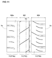
- FIG. 11 illustrates a development view of the tread pattern in accordance with another embodiment of the invention.
- a tire used for a rear wheel of a passenger vehicle is subjected to a low load condition where about 40% of the standard load is acted.
- the cornering power generated from such a rear tire would be small.
- a tire used for a rear wheel tends to be installed to the vehicle with negative camber.
- a tire for rear wheels preferably includes a tread pattern including an outboard shoulder land portion 11S o and an inboard shoulder portion 11S i having an axial width greater than that of the outboard shoulder land portion 11S o in order to increase a ground contact area of the inboard shoulder land portion 11S i to improve cornering power.
- the tread pattern includes the outboard shoulder land portion 11S o having an axial width WS o , the inboard shoulder land portion 11S i having an axial width WS i and the central land portion 11C having an axial width WC arranged therebetween.
- the outboard land portion 11S o is intended to be positioned towards away from a center of a vehicle body when the tire is installed to the vehicle.
- the inboard land portion 11S i is intended to be positioned towards the center of the vehicle body when the tire is installed to the vehicle.
- a ratio WS o / WC of the axial width WS o of the outboard shoulder land portion 11S o to the axial width WC of the central land portion 11C is set in a range of from 0.95 to 1.32.
- a ratio WS i / WC of the axial width WS i of the inboard shoulder land portion 11S i to the axial width WC of the central land portion 11C is set in a range of from 1.35 to 1.60.
- the tire according to the embodiment can improve cornering power by increasing the ground contact area of the inboard shoulder land portion 11S i when the tire is installed to a vehicle with negative camber.
- the ratio WS i / WC is less than 1.35, or the ratio WS o / WC is more than 1.32, the cornering power generated from the rear wheel with respect to the cornering power generated from the front wheel tends to be large relatively, thereby being deteriorated steering stability owing to oversteer behavior.
- the ratio WS i / WC is more than 1.6 or the ratio WS o / WC is less than 0.95, the wet grip performance may be deteriorated since the grooved area of the rear tire is not sufficient.
- Pneumatic tires having an internal structure shown in FIG. 1 were manufactured based on the specification in Table 1. Then, rolling resistance and air resistance of each test tire was tested. In each tire, the land ratio is set to 100%. Rolling resistance test:
- rolling resistance unit: N
- the test results were shown using an index of the reciprocal of the respective rolling resistance, wherein Sample 1 is set to 100. The larger the value, the lower the rolling resistance is.
- Pneumatic tires having the three-rib pattern ( FIG. 5 ) and the fourth-rib pattern (not shown) were manufactured based on the tire according to Sample 4. These configurations are shown in Table 2. Then, rolling resistance, steering stability and wet grip performance of each test tire was tested. Regarding each land ratio, it was adjusted by modifying the main groove widths, the lug groove widths, lengths and the number. Regarding rolling resistance test, the same test was conducted. The test results are indicated using an index based on Ref. 1 being 100. The larger the value, the lower the rolling resistance.
- cornering power of each test tire was measured under a condition of slip angle of 1 degree, internal pressure of 310 kPa and tire load of 4.82 kN.
- the test results are indicated using the cornering power index (Cp/W) which is calculated by dividing the cornering power (Cp) by the tire load (W).
- the tire load was defined as a 70% standard load for front and a 40% standard load for rear. The larger the value, the better the steering stability is.
- the tires having the three-rib pattern and a land ratio of not less than 85% may improve fuel consumption performance while ensuring wet performance as well as steering stability.
Landscapes
- Engineering & Computer Science (AREA)
- Mechanical Engineering (AREA)
- Tires In General (AREA)
Abstract
Description
- The present invention relates to a pneumatic tire capable of improving fuel consumption performance while ensuring wet performance as well as steering stability.
- As a factor of fuel economy in tires, rolling resistance of tires and air resistance is known. The major cause of rolling resistance of tires is energy loss due to repeated deformation of rubber during traveling. In order to reduce the rolling resistance, it has been proposed to use a tread rubber having low energy loss (low tan δ).
- When the tread rubber having low energy loss is used, although the rolling resistance decreases, grip performance, in particular wet grip performance, however, is lowered, and there is another problem that the abrasion resistance deteriorates. As shown in Japanese Unexamined Patent Application Publication Nos.
2004-010781 2004-002622 - In view of these circumstances, the present inventors who had conducted studies were able to find the following. When a tire section width is decreased while maintaining its tire outer diameter, the tread width is also decreased accordingly. Thus, the volume of the tread rubber is reduced. As a result, the energy loss caused by the tread rubber is reduced, and the weight of the tire is also lowered. Furthermore, when viewing a vehicle from its front, a tire exposed area appearing downwardly from a bumper edge of the vehicle is reduced according to the reduced tire section width. This makes it possible to reduce the air resistance of the tire.
- Furthermore, when a bead diameter is enlarged while maintaining its tire outer diameter, a sidewall region which tends to deform largely during traveling becomes narrow. As a result, a reduction in energy loss in the sidewall region as well as the weight of the tire can be achieved.
- Consequently, it has been confirmed that a narrow width and large bead diameter tire in which the tire section width is reduced while enlarging the bead diameter has significantly improved fuel consumption performance through reduction of energy loss in the tread portion and the sidewall portion, reduction of tire mass, and reduction of air resistance.
- Unfortunately, as a result of further study of the inventors of the present invention, in the above-mentioned narrow width and large bead diameter tire, steering stability tends to lower according to a narrow tire section width.
- The present invention has an object to provide a pneumatic tire, in particular, a narrow-width and large bead diameter tire capable of improving fuel consumption performance while ensuring wet performance as well as steering stability by basically employing a tread pattern including three rib-shaped land portions and a land ratio of not less than 85%.
- According to the present invention, a pneumatic tire comprises a carcass extending between bead cores of bead portions through a tread portion and a pair of sidewall portions. A tire section width Wt (unit: mm) in relation to a bead diameter Db (unit: inch) satisfies the following equations (1) and (2):


- In another aspect of the invention, the tread pattern may have lateral pattern rigidity in an axial direction of the tire in a range of from 2.8 to 3.2 kg/mm/mm.
- In another aspect of the invention, the tread pattern may have longitudinal pattern rigidity in a circumferential direction of the tire in a range of not less than 4.1 kg/mm/mm.
- In another aspect of the invention, the tread portion may comprise a tread rubber comprising a loss modulus E" of not more than 0.06 kg/mm2 and a loss compliance Ls of not more than 0.28 mm2/kg.
- In another aspect of the invention, the three rib-shaped land portions may comprise an outboard shoulder land portion having an axial width WSo, an inboard shoulder land portion having an axial width WSi and a central land portion having an axial width WC arranged therebetween, a ratio WSo/WC of the axial width WSo of the outboard shoulder land portion to the axial width WC of the central land portion may be in a range of from 0.95 to 1.32, and a ratio WSi/WC of the axial width WSi of the inboard shoulder land portion to the axial width WC of the central land portion may be in a range of from 1.35 to 1.60.
- As used herein, the loss modulus E" and the loss compliance Ls are values measured using a viscoelastic spectrometer according to provision of JIS-K 6394 under a condition of initial strain of 10%, amplitude of 2%, frequency of 10 Hz, a tensile strain mode and temperature of 30 degrees C.
- The pneumatic tire according to the present invention is configured as a tire having a narrow width and a large bead diameter satisfying the above mentioned equations (1) and (2). Therefore reduction of energy loss in the tread portion and the sidewall portion, reduction of tire weight, and reduction of air resistance may be achieved, thereby improving fuel consumption. While, since the tire having a narrow width and a large bead diameter has a narrow tread width, the steering stability may be deteriorated.
- In the present invention, the tread portion employs the tread pattern including three rib-shaped land portions and the land ratio of not less than 85%.
- The tire having a narrow width and a large bead diameter may deliver better draining performance as compared with conventional tires due to its narrow tread width. Thus, the tire according to the invention may employ a high land ratio, i.e., the land ratio of not less than 85%, while ensuring wet grip performance on the same levels with conventional tires. Furthermore, the tread pattern consisting of three rib-shaped land portions may have a higher lateral rigidity than the tread pattern consisting of four rib-shaped land portions, when they have the same tread width.
- Accordingly, the tire according to the present invention may increase cornering force while ensuring wet grip performance on the same levels with conventional tires and offering low fuel consumption, by employing the tread pattern having three rib-shaped land portions and a land ratio of not less than 85%. That is, the tire in accordance with the present invention may offer an excellent low fuel consumption performance while ensuring the wet performance as well as the steering stability.
-
-
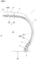
FIG. 1 is a cross sectional view of a pneumatic tire according to the present embodiment of the invention. -
FIG. 2 is a graph showing the relationship between a tire section width and a bead diameter of tires based on JATMA. -
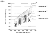
FIG. 3 is a graph showing the relationship between a tire section width and a tire outer diameter of tires based on JATMA. -
FIG. 4 is a conceptual diagram for explaining the effect of enlarged tire diameter. -
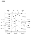
FIG. 5 is a development view of an example of a tread pattern. -
FIG. 6 is a graph showing the relationship among a land ratio, lateral pattern rigidity and cornering power index (Cp/W). -
FIG. 7 is a graph showing the relationship among a land ratio, lateral pattern rigidity and wet grip performance. -
FIG. 8 is a graph showing the relationship among a land ratio, longitudinal pattern rigidity and low rolling resistance index. -
FIG. 9 is a cross-sectional view of an example of a measurement device for measuring lateral and longitudinal rigidity of tire. -
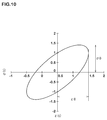
FIG. 10 is a stress-strain curve of a rubber. -
FIG. 11 is a development view of a tread pattern in accordance with another embodiment of the invention. - Hereinafter, an embodiment of the present invention will be described in detail in conjunction with accompanying drawings. As illustrated in
FIG. 1 , thepneumatic tire 1 in accordance with the present embodiment includes acarcass 6 extending betweenbead cores 5 ofbead portions 4 through atread portion 2 and a pair ofsidewall portions 3. In this embodiment, the tire further includes abelt layer 7 disposed radially outward of thecarcass 6 in thetread portion 2, and a reinforcingband layer 9 disposed radially outward of thebelt layer 7. - Preferably, the
carcass 6 includes onecarcass ply 6A of carcass cords oriented as an angle of 75 to 90 degrees with respect to the tire equatorial plane Co. Thecarcass ply 6A, for example, includes a toroidalmain body 6a extending between thebead cores 5 and a pair of turn-upportions 6b each turned up around eachbead core 5 from the axially inside to the outside of the tire. In each bead portion, a radially taperingbead apex rubber 8 which extends from thebead core 5 is disposed between themain portion 6a and the turn-upportions 6b. - The
belt layer 7, for example, includes twobelt plies belt plies tread portion 2 may be enhanced by hoop effect of thebelt layer 7 having high stiffness. - The
band layer 9A, for example, includes aspiral band ply 9A of a band cord formed by being wound spirally at an angle of not more than 5 degrees with respect to the tire equatorial plane Co. Theband layer 9 covers the substantially entire belt layer so as to restrain the movement of thebelt layer 7. Accordingly, growth of the tire outer diameter during high speed traveling, in particular growth of shoulder portion can be prevented. In this embodiment, theband layer 9 is configured to have an axial width greater than that of thebelt layer 7. - The
pneumatic tire 1 is configured as a narrow width and a large bead diameter tire in which the tire section width Wt (unit: mm) in relation to the bead diameter Db (unit: inch) satisfies the following equations (1) and (2),

-
FIG. 2 is a graph showing the relationship between the tire section width Wt and the bead diameter Db of tires based on JATMA. From this study result, the average relationship between the tire section width and the bead diameter of the conventional tires based on JATM, as indicated by one-dot chain line Ka in the Figure, it can be identified by the following equation (A):
- In contrast, the region Y1 that satisfies the equations (1) and (2) is outside the scope of the conventional tires shown in the plots. Furthermore, the region Y1 exists on the location where the relationship Ka identified by the equation (A) is moved parallel to a direction to decrease the tire section width Wt as well as to enlarge the bead diameter Db. That is, the tire satisfying the equations (1) and (2) is configured so as to have a narrow tire section width Wt and an enlarged bead diameter Db as compared with conventional tires having the same tire outer diameter.
- Such a tire with a narrow tire section width may provide a narrow tread width which offers less tread rubber volume accordingly. Therefore energy loss due to the tread rubber is relatively less, and the tire mass is also reduced. Furthermore, when a vehicle is viewed from its front, a tire exposed area appearing downwardly from a bumper edge is reduced according to the reduced tire section width. This makes it possible to reduce the air resistance of the tire.
- Furthermore, since the tire has an enlarged bead diameter as compared with conventional tires having the same tire outer diameter, a sidewall region, which tends to deform largely during traveling, becomes narrow. As a result, a reduction in energy loss by the
sidewall portion 3 as well as the weight of the tire can be achieved. - Accordingly, the tire having a narrow width and a large bead diameter may improve the fuel efficiency through a reduction in energy loss by the
tread portion 2 and thesidewall portions 3, a reduction in tire mass, and the reduction of air resistance. - When the tire section width Wt does not satisfy the equation (1), improvement of the fuel efficiency is insufficient owing to insufficient improvement reducing the section width or enlarging the bead diameter. When the tire does not satisfy the equation (2), the tire tends to have excessively narrow width. Such a tire may be necessary to be inflated with a high internal pressure in order to ensure use of under the load capacity. In this situation, ride comfort and road noise performance may be deteriorated.
- In order to further improve the fuel efficiency, the
pneumatic tire 1 has a tire outer diameter Dt (Unit: mm) satisfying the following equations (3) and (4):

-
FIG. 3 illustrates a graph showing the relationship between tire section widths Wt and tire outer diameters Dt of tires based on JATMA. From the study result, the average relationship between tire section widths Wt and tire outer diameters Dt of the conventional tire based on JATMA, as indicated by one-dot chain line Kb in the Figure, can be identified by the following equation (B):
- In contrast, the region Y2 that satisfies the equations (3) and (4) exists on the location where the relationship Kb identified by the equation (B) is moved parallel to a direction to enlarge the tire outer diameter Dt. That is, the tire satisfying the equations (3) and (4) has a narrow width, a large bead diameter and a large tire outer diameter Dt.
- The tire T1 with a relatively large outer diameter Dt, as conceptually shown in
FIG. 4 , is small in amount of bending deformation of the ground contacting portion in the circumferential direction of the tire as compared with the tire T2 with a relatively small outer diameter. Accordingly, the tire is small in energy loss and has advantageous effect of low rolling resistance. Therefore, when the tire does not satisfy the equation (4), low rolling resistance may not be expected. On the other hand, when the tire does not satisfy the equation (3), it may be necessary to be inflated with a high internal pressure to ensure necessary load capacity, and therefore ride comfort and road noise performance may be deteriorated. - As illustrated in
FIG. 5 , thetread portion 2 of thepneumatic tire 1 includes a tread pattern consisting of three rib-shapedland portions 11 separated by twolongitudinal grooves 10. The three rib-shapedland portions 11 include acentral land portion 11C disposed between themain grooves shoulder land portions 11S each disposed axially outward of eachmain groove 10. In this embodiment, themain grooves shoulder land portions 11S is the same as the axial width WS2 of the other one of theshoulder land portions 11S, for example. - The
tread portion 2 is provided with only twomain grooves 10 as a circumferentially and continuously extending groove which includes a sipe having a width of not more than 0.5 mm so as to close the width when coming into contact with the ground. Each rib-shapedland portion 11 is not provided with a lateral groove that extends across perfectly theland portion 11 to form a plurality of blocks. However, it is allowed to provide a sipe that extends across perfectly theland portion 11. Accordingly, each rib-shapedland portion 11 is formed as a rib that extends substantially continuously in the circumferential direction of the tire. - In this embodiment, the
central land portion 11C is provided with a plurality of central sipes 12C extending across thecentral land portion 11C. Eachshoulder land portion 11S is provided with a plurality oflug grooves 13S each extending axially inwardly from the tread edge Te and having an axially inner end E terminating within theshoulder land portion 11S and a plurality of first sipes 12S1 each extending from each inner end E of eachlug groove 13S, and at least one second sipe 12S2 arranged between a pair of circumferentiallyadjacent lug grooves 13S. In this embodiment, each second shoulder sipe 12S2 has at least one end, preferably both ends that terminate within theshoulder land portion 11S. - The tread pattern has a land ratio in a range of not less than 85% by adjusting widths of the
main grooves 10 and lengths, widths and the number of thelug grooves 13S, for example. Here, the land ratio is defined as a ratio Mb/Ma of a total area Mb of ground contact surface of the land portions to a tread gross surface area Ma obtained by adding the total ground contact surface of the land portions to the total area of the grooves. - The tire having a narrow width and a large bead diameter may deliver better draining performance as compared with conventional tires due to its narrow tread width. Thus, the tire according to the present embodiment may employ a high land ratio, i.e., the land ratio of not less than 85%, while ensuring wet grip performance on the same levels with conventional tires.
- Furthermore, the tread pattern consisting of three rib-shaped land portions 11 (hereinafter, it may be referred to as a "three-rib pattern P3") may have a higher lateral rigidity and generate a larger cornering force than the tread pattern consisting of four rib-shaped land portions 11 (hereinafter, it may be referred to as a four-rib pattern P4), when they have the same specification including the tread width except for tread pattern only.
-
FIG. 6 illustrates a graph showing the relationship among a land ratio, lateral pattern rigidity and cornering power index (Cp/W) of the respective three-rib pattern P3 and the four-rib tread pattern P4. In the graph, the numerals in parentheses indicate the land ratio. The cornering power index (Cp/W) is a dimensionless value obtained by dividing the cornering power (Cp) by the load (W). As illustrated inFIG. 6 , when the land ratio is the same, it has been confirmed that the three-rib pattern P3 exhibits high lateral pattern rigidity and generates a large cornering power index (Cp/W), as compared with the four-rib pattern P4. In particular, when the land ratio is not less than 85%, it is understood that the three-rib pattern P3 exhibits an excellent steering stability where the cornering power index (Cp/W) is equal to or more than 16. -
FIG. 7 is a graph showing the relationship among a land ratio, lateral pattern rigidity and wet grip performance of the respective three-rib pattern P3 and the four-rib tread pattern P4. In the graph, the numerals in parentheses indicate the land ratio. As illustrated inFIG.7 , when the land ratio is the same, it has been confirmed that there is no difference in wet grip performance between the three-rib pattern P3 and the four-rib pattern P4, and a sufficient wet grip performance can be obtained due to a narrow tread width even when the land ratio is set not less than 85%. In the graph ofFIG. 7 , the wet grip performance is evaluated using a speed in which a hydroplaning phenomenon occurs. - Preferably, the tread pattern has lateral pattern rigidity per a circumferential unit length of 1 mm in a range of from 2.8 to 3.2 kg/mm/mm. When the lateral pattern rigidity is less than 2.8 kg/mm/mm, it may be difficult to offer an excellent steering stability due to lack of cornering power index (Cp/W). On the other hand, when the lateral pattern rigidity is more than 3.2 kg/mm/mm, it may be difficult to offer an excellent wet grip performance since the drainage performance tends to deteriorate by difficulty of maintaining a necessary groove area. In view of wet grip performance, the land ratio is preferably set not more than 90%.
- Preferably, the tread pattern has longitudinal pattern rigidity per a circumferential unit length of 1 mm in a range of not less than 4.1 kg/mm/mm.
FIG. 8 is a graph showing the relationship among a land ratio, longitudinal pattern rigidity and low rolling resistance index of the three-rib pattern P3 obtained through inventor's experiments. In the graph, the numerals in parentheses indicate the land ratio. As illustrated inFIG. 8 , it has been confirmed that the low rolling resistance performance improves according to increase of the longitudinal pattern rigidity. When the land ratio tends to be high, the temperature of the tread rubber may rise since heat dissipation property of the tread portion tends to be lower. On the other hand, hysteresis loss of rubber tends to be lower according to temperature rise of the rubber. That is, a tire having a high land ratio (high pattern rigidity) exhibits a low rolling resistance, since the hysteresis loss of the rubber is lowered according to temperature rise of the rubber due to heat storage. Furthermore, since the tire according to the embodiment includes a narrow width and a large bead diameter, the behavior of the tread is influenced by the longitudinal pattern rigidity more than the lateral pattern rigidity. Accordingly, in order to enhance pattern rigidity of the tread portion, it may be possible to improve low rolling performance of the tire. Furthermore, the longitudinal pattern rigidity is less than 4.1 kg/mm/mm, it may be difficult to maintain low rolling resistance performance. - The lateral pattern rigidity and the longitudinal pattern rigidity of the tread pattern may be measured using a
measurement device 19 as illustrated inFIG. 9 . Thedevice 19 includes abase 21, a mount table 20 on which ameasurement sample piece 22 of a tread pattern is mounted and which can move on the base 21 in the x-direction, a fixingplate 23 for fixing the sample piece toward the mount table 20, a load sensor (e.g. load cell) 24 for measuring a load acting on the mount table 20 in the x-direction, and adistance sensor 25 for measuring a moving distance of the mount table in the x-direction. - The
measurement sample 22 is prepared from the tread rubber G cut out from thepneumatic tire 1. Alternatively, themeasurement sample 22 can be prepared from a replica G of the tread rubber G if it has the same size, pattern and rubber composition as the tread rubber G. Themeasurement sample 22 is firmly fixed to the mount table 20 using an adhesive agent so that thesamples 22 and the mount table 20 can move together. Furthermore, thebase tread portion 22b of themeasurement sample 22 is fixed by astopper piece 20A on the mount table 20 so that thebase portion 22b cannot deform. In addition, the ground contact surface of themeasurement sample 22 may be fixed to the fixingplate 23 using an adhesive agent so as to prevent slippage therebetween. In an embodiment to use themeasurement device 19, the displacement t in the X-direction of the mount table 20 is measured under the condition where the mount table 20 receives a vertical force F0 through the measurement sample and a lateral force f in the X-direction. The vertical force F0 (kgf), for example, may be defined as follows:
measurement sample 22. - When the longitudinal pattern rigidity is measured, the
measurement sample 22 is mounted on the mount table 20 so that the circumferential direction of the sample is along the X-direction of themeasurement device 19. Then, the longitudinal pattern rigidity of the tread portion is defined, in relation to the sample length L, the lateral force f and the displacement t of the mount table 20, as follows:
- When the lateral pattern rigidity is measured, the
measurement sample 22 is mounted on the mount table 20 so that the circumferential direction of the sample is perpendicular to the X-direction of themeasurement device 19. Then, the lateral pattern rigidity of the tread portion is defined, in relation to the sample length L, the lateral force f and the displacement t of the mount table 20, as follows:
- Furthermore, the
pneumatic tire 1 preferably includes the tread rubber G having a loss modulus E" of not more than 0.06 kg/mm2 and a loss compliance Ls of not more than 0.28 mm2/kg. Note that the loss modulus E" and the loss compliance Ls of the tread rubber are defined as values of the radially outermost ground contact layer when the tread rubber G is formed of a plurality of rubber layers. -
FIG. 10 illustrates a stress-strain curve of a rubber under forced vibration. Here, the hysteresis loss Q is expressed by (A) and (B):

- The hysteresis loss Q depends on the loss modulus E" when the strain ε0 is constant. Accordingly, it is possible to reduce the rolling resistance of the tire by lowering the loss modulus E" of the tread rubber. Furthermore, the hysteresis loss Q depends on the loss compliance Ls when the stress σ0 is constant. Accordingly, it is possible to reduce the rolling resistance of the tire by lowering the loss compliance Lc of the tread rubber.
- The present inventors have found that a strain-constant behavior of the tread portion is mainly caused by a bending deformation, and a stress-constant behavior of the tread portion is mainly caused by a compressive deformation. Meanwhile, in the tire having a narrow width and a large bead diameter according to the embodiment, a large bending deformation of the tread portion may be caused owing to its narrow tread width and its long ground contact patch. Thus, the hysteresis loss Q of the tread rubber can be reduced effectively by lowering the loss modulus E" of the tread rubber. Furthermore, since the tire having a narrow width and a large bead diameter according to the embodiment tends to exhibit low load index as compared with conventional tires, the tire may be used with a high internal pressure in order to ensure a required load index. Thus, the hysteresis loss Q of the tread rubber can also be reduced effectively by lowering the loss compliance Lc of the tread rubber.
- As described above, the tire having a narrow width and a large bead diameter may offer low rolling resistance by lowering the hysteresis loss Q of the tread rubber based on the tread rubber with the loss modulus E" of not more than 0.06 kg/mm2 and the loss compliance Lc of not more than 0.28 mm2/kg. When the loss modulus E" is less than 0.04kg/mm2 or the loss compliance Lc is less than 0.20mm2/kg, the wet grip performance may be deteriorated since the storage modulus E' tends to increase. Preferably, the loss modulus E" is not less than 0.04 kg/mm2, and preferably the loss compliance Lc is not less than 0.20kg/mm2.
-
FIG. 11 illustrates a development view of the tread pattern in accordance with another embodiment of the invention. In general, a tire used for a rear wheel of a passenger vehicle is subjected to a low load condition where about 40% of the standard load is acted. Thus, the cornering power generated from such a rear tire would be small. Furthermore, a tire used for a rear wheel tends to be installed to the vehicle with negative camber. Accordingly, a tire for rear wheels preferably includes a tread pattern including an outboardshoulder land portion 11So and aninboard shoulder portion 11Si having an axial width greater than that of the outboardshoulder land portion 11So in order to increase a ground contact area of the inboardshoulder land portion 11Si to improve cornering power. - In this embodiment, the tread pattern includes the outboard
shoulder land portion 11So having an axial width WSo, the inboardshoulder land portion 11Si having an axial width WSi and thecentral land portion 11C having an axial width WC arranged therebetween. Here, theoutboard land portion 11So is intended to be positioned towards away from a center of a vehicle body when the tire is installed to the vehicle. Theinboard land portion 11Si is intended to be positioned towards the center of the vehicle body when the tire is installed to the vehicle. - Preferably, a ratio WSo / WC of the axial width WSo of the outboard
shoulder land portion 11So to the axial width WC of thecentral land portion 11C is set in a range of from 0.95 to 1.32. Preferably, a ratio WSi / WC of the axial width WSi of the inboardshoulder land portion 11Si to the axial width WC of thecentral land portion 11C is set in a range of from 1.35 to 1.60. - Accordingly, the tire according to the embodiment can improve cornering power by increasing the ground contact area of the inboard
shoulder land portion 11Si when the tire is installed to a vehicle with negative camber. When the ratio WSi / WC is less than 1.35, or the ratio WSo / WC is more than 1.32, the cornering power generated from the rear wheel with respect to the cornering power generated from the front wheel tends to be large relatively, thereby being deteriorated steering stability owing to oversteer behavior. On the other hand, when the ratio WSi / WC is more than 1.6 or the ratio WSo / WC is less than 0.95, the wet grip performance may be deteriorated since the grooved area of the rear tire is not sufficient. - While the particularly preferable embodiments in accordance with the present invention have been described in detail, the present invention is not limited to the illustrated embodiments, but can be modified and carried out in various aspects.
- Pneumatic tires having an internal structure shown in
FIG. 1 were manufactured based on the specification in Table 1. Then, rolling resistance and air resistance of each test tire was tested. In each tire, the land ratio is set to 100%. Rolling resistance test: - Using a rolling resistance tester, under the following conditions, rolling resistance (unit: N) of each test tire was measured. The test results were shown using an index of the reciprocal of the respective rolling resistance, wherein
Sample 1 is set to 100. The larger the value, the lower the rolling resistance is. - Temperature: 20 degrees C.
- Load: 4.8 kN
- Internal pressure: Listed in Table 1
- Rim: Standard rim
- Speed: 80 km/h
-
- Toe angle: 0 deg.
- Camber angle: 0 deg.
- In a laboratory, a force received from each test tire installed to a vehicle was measured under the condition where the air with a speed corresponding to the vehicle running speed of 100 km/hr was provided toward the test tire exposed from a lower edge of the bumper, wherein the tire exposed height was set to 140 mm. The test results were shown using an index of the reciprocal of the respective forces, wherein
Sample 1 is set to 100. The larger the value, the better the air resistance is.Table 1 Sample 1Sample 2Sample 3Sample 4Tire section width Wt (mm) 195 165 165 165 Aspect ratio H (%) 65 65 65 65 Bead diameter Db (inch) 15 16 18 19 Load index LI 91 81 84 85 Internal pressure (kPa) 250 350 320 310 Tire load (kN) 4.82 4.82 4.82 4.82 Rim width (inch) 6 5 5 5 Tire outer diameter Dt (mm) 634.5 620.9 671.7 697.1 Satisfying equations (1) and (2) No No Yes Yes Satisfying equations (3) and (4) No No Yes Yes Rolling resistance test 100 102 103 104 Air resistance 100 114 114 114 - From the test results, it has been confirmed that the tires of
Samples - Pneumatic tires having the three-rib pattern (
FIG. 5 ) and the fourth-rib pattern (not shown) were manufactured based on the tire according toSample 4. These configurations are shown in Table 2. Then, rolling resistance, steering stability and wet grip performance of each test tire was tested. Regarding each land ratio, it was adjusted by modifying the main groove widths, the lug groove widths, lengths and the number. Regarding rolling resistance test, the same test was conducted. The test results are indicated using an index based on Ref. 1 being 100. The larger the value, the lower the rolling resistance. - In a laboratory, cornering power of each test tire was measured under a condition of slip angle of 1 degree, internal pressure of 310 kPa and tire load of 4.82 kN. The test results are indicated using the cornering power index (Cp/W) which is calculated by dividing the cornering power (Cp) by the tire load (W). The tire load was defined as a 70% standard load for front and a 40% standard load for rear. The larger the value, the better the steering stability is.
- In a laboratory, hydroplaning occurring speed of each test tire was measured under a condition of slip angle of 1 degree, internal pressure of 310 kPa and tire load of 4.82 kN.
Table 2 Ref. 1 Ref. 2 Ref. 3 Ref. 4 Ex. 1 Ex. 2 Ex. 3 Ex. 4 Number of ribs in tread portion 4 4 4 3 3 3 3 3 Land ratio (%) 80 85 90 80 85 85 85 90 Longitudinal pattern rigidity (kg/mm/mm) 4.71 5.22 5.57 4.03 4.37 4.13 3.88 4.67 Lateral pattern rigidity (kg/mm/mm) 2.54 2.81 3.00 2.82 3.06 3.02 2.98 3.24 Rolling resistance test 104.0 104.0 102.7 103.1 104.6 103.9 102.0 106.7 Wet grip performance 94 89 84 97 88 88 91 80 Cornering power index (Cp/W) 15.6 15.8 16.2 15.5 16.2 16.3 16.2 16.6 - As shown in Table 2, it has been confirmed that the tires having the three-rib pattern and a land ratio of not less than 85% may improve fuel consumption performance while ensuring wet performance as well as steering stability.
- Pneumatic tires having the three-rib pattern (
FIG. 5 ) and the land ratio of 85% were manufactured based on the tire according toSample 4. These configurations are shown in Table 3. Then, rolling resistance and wet grip performance of each test tire was tested.Table 3 Ex. 5 Ex. 6 Ex. 7 Ex. 8 Ex. 9 Number of ribs in tread portion 3 3 3 3 3 Land ratio (%) 85 85 85 85 85 Tread rubber loss modulus E" (kg/mm2) 0.112 0.089 0.051 0.098 0.058 Tread rubber loss compliance Lc (mm2/kg) 0.37 0.211 0.276 0.268 0.239 Rolling resistance test 104 111 115 110 117 Wet grip performance 100 93 90 95 90 - Pneumatic tires having the three-rib pattern (
FIG. 5 ) were manufactured based on the tire according toSample 4. These configurations are shown in Table 4. Then, rolling resistance, wet grip performance and steering stability of each test tire was tested. Regarding steering stability, the test was conducted in the same manner except setting the negative camber of 1 degree.Table 4 Ex. 10 Ex. 11 Ex. 12 Ex. 13 Ex. 14 Ex. 15 Tread pattern 3 3 3 3 3 3 Land ratio (%) 85 85 85 85 85 85 WSo (mm) 37 26 35 31 27 23 WC (mm) 14 31 25 25 25 25 WSi (mm) 36 29 29 33 37 41 Ratio WSo / WC 2.64 0.84 1.40 1.24 1.08 0.92 Ratio WSi / WC 2.57 0.94 1.16 1.32 1.48 1.64 Rolling resistance test 105 105 105 105 105 105 Wet grip performance 89 87 88 88 88 86 Front (Cp/W) 21.8 22.0 22.0 21.9 21.9 21.8 Rear (Cp/W) 23.5 23.9 23.5 23.8 24.1 24.4
Claims (5)
- A pneumatic tire comprising:a carcass extending between bead cores of bead portions through a tread portion and a pair of sidewall portions;a tire section width Wt (unit: mm) in relation to a bead diameter Db (unit: inch) satisfying the following equations (1) and (2),

 the tread portion comprising a tread pattern comprising three rib-shaped land portions separated by two longitudinal grooves; anda land ratio of the tread pattern being not less than 85%.
 - The pneumatic tire according to claim 1,
wherein the tread pattern has lateral pattern rigidity in an axial direction of the tire in a range of from 2.8 to 3.2 kg/mm/mm. - The pneumatic tire according to claim 1 or 2,
wherein the tread pattern has longitudinal pattern rigidity in a circumferential direction of the tire in a range of not less than 4.1 kg/mm/mm. - The pneumatic tire according to any one of claims 1 to 3,
wherein the tread portion comprises a tread rubber comprising a loss modulus E" of not more than 0.06 kg/mm2 and a loss compliance Ls of not more than 0.28 mm2/kg. - The pneumatic tire according to any one of claims 1 to 4,
wherein the three rib-shaped land portions comprise an outboard shoulder land portion having an axial width WSo, an inboard shoulder land portion having an axial width WSi and a central land portion having an axial width WC arranged therebetween, a ratio WSo / WC of the axial width WSo of the outboard shoulder land portion to the axial width WC of the central land portion is in a range of from 0.95 to 1.32, and a ratio WSi / WC of the axial width WSi of the inboard shoulder land portion to the axial width WC of the central land portion is in a range of from 1.35 to 1.60.
Applications Claiming Priority (1)
| Application Number | Priority Date | Filing Date | Title |
|---|---|---|---|
| JP2015054636A JP6405273B2 (en) | 2015-03-18 | 2015-03-18 | Pneumatic tire |
Publications (2)
| Publication Number | Publication Date |
|---|---|
| EP3069899A1 true EP3069899A1 (en) | 2016-09-21 |
| EP3069899B1 EP3069899B1 (en) | 2018-01-17 |
Family
ID=55586131
Family Applications (1)
| Application Number | Title | Priority Date | Filing Date |
|---|---|---|---|
| EP16158366.1A Active EP3069899B1 (en) | 2015-03-18 | 2016-03-03 | Pneumatic tire |
Country Status (3)
| Country | Link |
|---|---|
| EP (1) | EP3069899B1 (en) |
| JP (1) | JP6405273B2 (en) |
| CN (1) | CN105984281B (en) |
Cited By (1)
| Publication number | Priority date | Publication date | Assignee | Title |
|---|---|---|---|---|
| EP4245568A1 (en) * | 2022-03-15 | 2023-09-20 | Sumitomo Rubber Industries, Ltd. | Tire |
Families Citing this family (3)
| Publication number | Priority date | Publication date | Assignee | Title |
|---|---|---|---|---|
| JP7140665B2 (en) * | 2018-12-12 | 2022-09-21 | Toyo Tire株式会社 | pneumatic tire |
| JP7385107B2 (en) * | 2019-08-08 | 2023-11-22 | 横浜ゴム株式会社 | pneumatic tires |
| JP6769573B1 (en) * | 2020-02-28 | 2020-10-14 | 住友ゴム工業株式会社 | tire |
Citations (6)
| Publication number | Priority date | Publication date | Assignee | Title |
|---|---|---|---|---|
| JP2004002622A (en) | 2002-03-27 | 2004-01-08 | Sumitomo Rubber Ind Ltd | Rubber composition |
| JP2004010781A (en) | 2002-06-07 | 2004-01-15 | Sumitomo Rubber Ind Ltd | Rubber composition |
| EP2724871A1 (en) * | 2011-06-22 | 2014-04-30 | Bridgestone Corporation | Pneumatic radial tire for passenger car, method for using tire, and tire/rim assembly with tire |
| EP2738015A1 (en) * | 2011-07-28 | 2014-06-04 | Bridgestone Corporation | Pneumatic radial tire for passenger vehicle and method for using same |
| EP2738016A1 (en) * | 2011-07-28 | 2014-06-04 | Bridgestone Corporation | Pneumatic radial tire for passenger vehicle and method for using same |
| WO2014132551A1 (en) * | 2013-02-28 | 2014-09-04 | 株式会社ブリヂストン | Pneumatic radial tire for passenger vehicle |
Family Cites Families (5)
| Publication number | Priority date | Publication date | Assignee | Title |
|---|---|---|---|---|
| JPS52118705A (en) * | 1976-03-23 | 1977-10-05 | Toyo Tire & Rubber Co Ltd | Automotive tire with low rolling resistance |
| JPS5940642B2 (en) * | 1979-06-01 | 1984-10-02 | 住友ゴム工業株式会社 | Radial tires for passenger cars |
| JPS56163906A (en) * | 1980-05-20 | 1981-12-16 | Sumitomo Rubber Ind Ltd | Heavy duty pneumatic tyre |
| US9511630B2 (en) * | 2011-11-02 | 2016-12-06 | Bridgestone Corporation | Pneumatic radial tire for passenger vehicle and method for using the same |
| JP2015030428A (en) * | 2013-08-06 | 2015-02-16 | 住友ゴム工業株式会社 | Pneumatic tire |
-
2015
- 2015-03-18 JP JP2015054636A patent/JP6405273B2/en active Active
-
2016
- 2016-03-03 EP EP16158366.1A patent/EP3069899B1/en active Active
- 2016-03-04 CN CN201610124166.3A patent/CN105984281B/en active Active
Patent Citations (7)
| Publication number | Priority date | Publication date | Assignee | Title |
|---|---|---|---|---|
| JP2004002622A (en) | 2002-03-27 | 2004-01-08 | Sumitomo Rubber Ind Ltd | Rubber composition |
| JP2004010781A (en) | 2002-06-07 | 2004-01-15 | Sumitomo Rubber Ind Ltd | Rubber composition |
| EP2724871A1 (en) * | 2011-06-22 | 2014-04-30 | Bridgestone Corporation | Pneumatic radial tire for passenger car, method for using tire, and tire/rim assembly with tire |
| EP2738015A1 (en) * | 2011-07-28 | 2014-06-04 | Bridgestone Corporation | Pneumatic radial tire for passenger vehicle and method for using same |
| EP2738016A1 (en) * | 2011-07-28 | 2014-06-04 | Bridgestone Corporation | Pneumatic radial tire for passenger vehicle and method for using same |
| WO2014132551A1 (en) * | 2013-02-28 | 2014-09-04 | 株式会社ブリヂストン | Pneumatic radial tire for passenger vehicle |
| EP2962874A1 (en) * | 2013-02-28 | 2016-01-06 | Bridgestone Corporation | Pneumatic radial tire for passenger vehicle |
Non-Patent Citations (2)
| Title |
|---|
| LONGSTONE TYRES: "Citroen 2cv | Longstone Tyres", LONGSTONETYRES.CO.UK, 24 February 2015 (2015-02-24), XP055171748, Retrieved from the Internet <URL:http://www.longstonetyres.co.uk/page/citroen-2cv> [retrieved on 20150224] * |
| MICHELIN: "MICHELIN X", LAVENTUREMICHELIN.COM, 1 January 1950 (1950-01-01), pages 1 - 2, XP055171753, Retrieved from the Internet <URL:http://www.laventuremichelin.com/scolaires_et_enseignants/DOCS/radial_small.jpg> [retrieved on 20150224] * |
Cited By (1)
| Publication number | Priority date | Publication date | Assignee | Title |
|---|---|---|---|---|
| EP4245568A1 (en) * | 2022-03-15 | 2023-09-20 | Sumitomo Rubber Industries, Ltd. | Tire |
Also Published As
| Publication number | Publication date |
|---|---|
| EP3069899B1 (en) | 2018-01-17 |
| CN105984281A (en) | 2016-10-05 |
| CN105984281B (en) | 2019-06-25 |
| JP6405273B2 (en) | 2018-10-17 |
| JP2016172540A (en) | 2016-09-29 |
Similar Documents
| Publication | Publication Date | Title |
|---|---|---|
| EP2781372B1 (en) | Pneumatic radial tire for passenger car and method for use thereof | |
| US9505269B2 (en) | Pneumatic tire with tread having central main groove, shoulder main grooves and sipes | |
| JP5781610B2 (en) | Pneumatic radial tire for passenger cars and method of using the same | |
| EP2781373B1 (en) | Pneumatic tire | |
| US7036541B2 (en) | Pneumatic tire | |
| EP3202596B1 (en) | Run-flat tire | |
| KR101677304B1 (en) | Pneumatic tire | |
| EP2962874B1 (en) | Pneumatic radial tire for passenger vehicle | |
| EP3332991B1 (en) | Pneumatic tire | |
| EP3069899B1 (en) | Pneumatic tire | |
| US10195900B2 (en) | Pneumatic tire with specified tread thickness distribution and specified section width in relation to bead diameter | |
| EP3597453B1 (en) | Pneumatic tyre | |
| US20160193874A1 (en) | Pneumatic tire | |
| EP3059100B1 (en) | Pneumatic tire | |
| JP2018111360A (en) | Pneumatic tire | |
| WO2016024390A1 (en) | Pneumatic tire | |
| JP2003146015A (en) | Pneumatic tire | |
| EP4353494A1 (en) | Pneumatic radial tire for passenger vehicle | |
| EP4360907A1 (en) | Pneumatic radial tire for passenger vehicle | |
| EP4360912A1 (en) | Pneumatic radial tire for passenger vehicle | |
| EP4353496A1 (en) | Pneumatic radial tire for passenger vehicle | |
| EP4357157A1 (en) | Pneumatic radial tire for passenger car | |
| JP2010254249A (en) | Pneumatic tire |
Legal Events
| Date | Code | Title | Description |
|---|---|---|---|
| PUAI | Public reference made under article 153(3) epc to a published international application that has entered the european phase |
Free format text: ORIGINAL CODE: 0009012 |
|
| AK | Designated contracting states |
Kind code of ref document: A1 Designated state(s): AL AT BE BG CH CY CZ DE DK EE ES FI FR GB GR HR HU IE IS IT LI LT LU LV MC MK MT NL NO PL PT RO RS SE SI SK SM TR |
|
| AX | Request for extension of the european patent |
Extension state: BA ME |
|
| 17P | Request for examination filed |
Effective date: 20170126 |
|
| RBV | Designated contracting states (corrected) |
Designated state(s): AL AT BE BG CH CY CZ DE DK EE ES FI FR GB GR HR HU IE IS IT LI LT LU LV MC MK MT NL NO PL PT RO RS SE SI SK SM TR |
|
| GRAP | Despatch of communication of intention to grant a patent |
Free format text: ORIGINAL CODE: EPIDOSNIGR1 |
|
| RIC1 | Information provided on ipc code assigned before grant |
Ipc: B60C 3/04 20060101AFI20170623BHEP Ipc: B60C 11/03 20060101ALI20170623BHEP |
|
| INTG | Intention to grant announced |
Effective date: 20170801 |
|
| GRAS | Grant fee paid |
Free format text: ORIGINAL CODE: EPIDOSNIGR3 |
|
| GRAA | (expected) grant |
Free format text: ORIGINAL CODE: 0009210 |
|
| AK | Designated contracting states |
Kind code of ref document: B1 Designated state(s): AL AT BE BG CH CY CZ DE DK EE ES FI FR GB GR HR HU IE IS IT LI LT LU LV MC MK MT NL NO PL PT RO RS SE SI SK SM TR |
|
| REG | Reference to a national code |
Ref country code: GB Ref legal event code: FG4D |
|
| REG | Reference to a national code |
Ref country code: CH Ref legal event code: EP |
|
| REG | Reference to a national code |
Ref country code: IE Ref legal event code: FG4D |
|
| REG | Reference to a national code |
Ref country code: AT Ref legal event code: REF Ref document number: 964157 Country of ref document: AT Kind code of ref document: T Effective date: 20180215 |
|
| REG | Reference to a national code |
Ref country code: DE Ref legal event code: R096 Ref document number: 602016001327 Country of ref document: DE |
|
| REG | Reference to a national code |
Ref country code: FR Ref legal event code: PLFP Year of fee payment: 3 |
|
| REG | Reference to a national code |
Ref country code: NL Ref legal event code: MP Effective date: 20180117 |
|
| REG | Reference to a national code |
Ref country code: LT Ref legal event code: MG4D |
|
| REG | Reference to a national code |
Ref country code: AT Ref legal event code: MK05 Ref document number: 964157 Country of ref document: AT Kind code of ref document: T Effective date: 20180117 |
|
| PG25 | Lapsed in a contracting state [announced via postgrant information from national office to epo] |
Ref country code: NL Free format text: LAPSE BECAUSE OF FAILURE TO SUBMIT A TRANSLATION OF THE DESCRIPTION OR TO PAY THE FEE WITHIN THE PRESCRIBED TIME-LIMIT Effective date: 20180117 |
|
| PG25 | Lapsed in a contracting state [announced via postgrant information from national office to epo] |
Ref country code: LT Free format text: LAPSE BECAUSE OF FAILURE TO SUBMIT A TRANSLATION OF THE DESCRIPTION OR TO PAY THE FEE WITHIN THE PRESCRIBED TIME-LIMIT Effective date: 20180117 Ref country code: ES Free format text: LAPSE BECAUSE OF FAILURE TO SUBMIT A TRANSLATION OF THE DESCRIPTION OR TO PAY THE FEE WITHIN THE PRESCRIBED TIME-LIMIT Effective date: 20180117 Ref country code: HR Free format text: LAPSE BECAUSE OF FAILURE TO SUBMIT A TRANSLATION OF THE DESCRIPTION OR TO PAY THE FEE WITHIN THE PRESCRIBED TIME-LIMIT Effective date: 20180117 Ref country code: NO Free format text: LAPSE BECAUSE OF FAILURE TO SUBMIT A TRANSLATION OF THE DESCRIPTION OR TO PAY THE FEE WITHIN THE PRESCRIBED TIME-LIMIT Effective date: 20180417 Ref country code: FI Free format text: LAPSE BECAUSE OF FAILURE TO SUBMIT A TRANSLATION OF THE DESCRIPTION OR TO PAY THE FEE WITHIN THE PRESCRIBED TIME-LIMIT Effective date: 20180117 Ref country code: CY Free format text: LAPSE BECAUSE OF FAILURE TO SUBMIT A TRANSLATION OF THE DESCRIPTION OR TO PAY THE FEE WITHIN THE PRESCRIBED TIME-LIMIT Effective date: 20180117 |
|
| PG25 | Lapsed in a contracting state [announced via postgrant information from national office to epo] |
Ref country code: AT Free format text: LAPSE BECAUSE OF FAILURE TO SUBMIT A TRANSLATION OF THE DESCRIPTION OR TO PAY THE FEE WITHIN THE PRESCRIBED TIME-LIMIT Effective date: 20180117 Ref country code: RS Free format text: LAPSE BECAUSE OF FAILURE TO SUBMIT A TRANSLATION OF THE DESCRIPTION OR TO PAY THE FEE WITHIN THE PRESCRIBED TIME-LIMIT Effective date: 20180117 Ref country code: PL Free format text: LAPSE BECAUSE OF FAILURE TO SUBMIT A TRANSLATION OF THE DESCRIPTION OR TO PAY THE FEE WITHIN THE PRESCRIBED TIME-LIMIT Effective date: 20180117 Ref country code: IS Free format text: LAPSE BECAUSE OF FAILURE TO SUBMIT A TRANSLATION OF THE DESCRIPTION OR TO PAY THE FEE WITHIN THE PRESCRIBED TIME-LIMIT Effective date: 20180517 Ref country code: GR Free format text: LAPSE BECAUSE OF FAILURE TO SUBMIT A TRANSLATION OF THE DESCRIPTION OR TO PAY THE FEE WITHIN THE PRESCRIBED TIME-LIMIT Effective date: 20180418 Ref country code: SE Free format text: LAPSE BECAUSE OF FAILURE TO SUBMIT A TRANSLATION OF THE DESCRIPTION OR TO PAY THE FEE WITHIN THE PRESCRIBED TIME-LIMIT Effective date: 20180117 Ref country code: LV Free format text: LAPSE BECAUSE OF FAILURE TO SUBMIT A TRANSLATION OF THE DESCRIPTION OR TO PAY THE FEE WITHIN THE PRESCRIBED TIME-LIMIT Effective date: 20180117 Ref country code: BG Free format text: LAPSE BECAUSE OF FAILURE TO SUBMIT A TRANSLATION OF THE DESCRIPTION OR TO PAY THE FEE WITHIN THE PRESCRIBED TIME-LIMIT Effective date: 20180417 |
|
| REG | Reference to a national code |
Ref country code: DE Ref legal event code: R097 Ref document number: 602016001327 Country of ref document: DE |
|
| PG25 | Lapsed in a contracting state [announced via postgrant information from national office to epo] |
Ref country code: AL Free format text: LAPSE BECAUSE OF FAILURE TO SUBMIT A TRANSLATION OF THE DESCRIPTION OR TO PAY THE FEE WITHIN THE PRESCRIBED TIME-LIMIT Effective date: 20180117 Ref country code: IT Free format text: LAPSE BECAUSE OF FAILURE TO SUBMIT A TRANSLATION OF THE DESCRIPTION OR TO PAY THE FEE WITHIN THE PRESCRIBED TIME-LIMIT Effective date: 20180117 Ref country code: EE Free format text: LAPSE BECAUSE OF FAILURE TO SUBMIT A TRANSLATION OF THE DESCRIPTION OR TO PAY THE FEE WITHIN THE PRESCRIBED TIME-LIMIT Effective date: 20180117 Ref country code: RO Free format text: LAPSE BECAUSE OF FAILURE TO SUBMIT A TRANSLATION OF THE DESCRIPTION OR TO PAY THE FEE WITHIN THE PRESCRIBED TIME-LIMIT Effective date: 20180117 |
|
| PLBE | No opposition filed within time limit |
Free format text: ORIGINAL CODE: 0009261 |
|
| STAA | Information on the status of an ep patent application or granted ep patent |
Free format text: STATUS: NO OPPOSITION FILED WITHIN TIME LIMIT |
|
| PG25 | Lapsed in a contracting state [announced via postgrant information from national office to epo] |
Ref country code: SM Free format text: LAPSE BECAUSE OF FAILURE TO SUBMIT A TRANSLATION OF THE DESCRIPTION OR TO PAY THE FEE WITHIN THE PRESCRIBED TIME-LIMIT Effective date: 20180117 Ref country code: SK Free format text: LAPSE BECAUSE OF FAILURE TO SUBMIT A TRANSLATION OF THE DESCRIPTION OR TO PAY THE FEE WITHIN THE PRESCRIBED TIME-LIMIT Effective date: 20180117 Ref country code: CZ Free format text: LAPSE BECAUSE OF FAILURE TO SUBMIT A TRANSLATION OF THE DESCRIPTION OR TO PAY THE FEE WITHIN THE PRESCRIBED TIME-LIMIT Effective date: 20180117 Ref country code: MC Free format text: LAPSE BECAUSE OF FAILURE TO SUBMIT A TRANSLATION OF THE DESCRIPTION OR TO PAY THE FEE WITHIN THE PRESCRIBED TIME-LIMIT Effective date: 20180117 Ref country code: DK Free format text: LAPSE BECAUSE OF FAILURE TO SUBMIT A TRANSLATION OF THE DESCRIPTION OR TO PAY THE FEE WITHIN THE PRESCRIBED TIME-LIMIT Effective date: 20180117 |
|
| REG | Reference to a national code |
Ref country code: BE Ref legal event code: MM Effective date: 20180331 |
|
| 26N | No opposition filed |
Effective date: 20181018 |
|
| REG | Reference to a national code |
Ref country code: IE Ref legal event code: MM4A |
|
| PG25 | Lapsed in a contracting state [announced via postgrant information from national office to epo] |
Ref country code: LU Free format text: LAPSE BECAUSE OF NON-PAYMENT OF DUE FEES Effective date: 20180303 |
|
| PG25 | Lapsed in a contracting state [announced via postgrant information from national office to epo] |
Ref country code: IE Free format text: LAPSE BECAUSE OF NON-PAYMENT OF DUE FEES Effective date: 20180303 |
|
| PG25 | Lapsed in a contracting state [announced via postgrant information from national office to epo] |
Ref country code: SI Free format text: LAPSE BECAUSE OF FAILURE TO SUBMIT A TRANSLATION OF THE DESCRIPTION OR TO PAY THE FEE WITHIN THE PRESCRIBED TIME-LIMIT Effective date: 20180117 Ref country code: BE Free format text: LAPSE BECAUSE OF NON-PAYMENT OF DUE FEES Effective date: 20180331 |
|
| REG | Reference to a national code |
Ref country code: CH Ref legal event code: PL |
|
| PG25 | Lapsed in a contracting state [announced via postgrant information from national office to epo] |
Ref country code: CH Free format text: LAPSE BECAUSE OF NON-PAYMENT OF DUE FEES Effective date: 20190331 Ref country code: MT Free format text: LAPSE BECAUSE OF NON-PAYMENT OF DUE FEES Effective date: 20180303 Ref country code: LI Free format text: LAPSE BECAUSE OF NON-PAYMENT OF DUE FEES Effective date: 20190331 |
|
| PG25 | Lapsed in a contracting state [announced via postgrant information from national office to epo] |
Ref country code: TR Free format text: LAPSE BECAUSE OF FAILURE TO SUBMIT A TRANSLATION OF THE DESCRIPTION OR TO PAY THE FEE WITHIN THE PRESCRIBED TIME-LIMIT Effective date: 20180117 |
|
| PG25 | Lapsed in a contracting state [announced via postgrant information from national office to epo] |
Ref country code: PT Free format text: LAPSE BECAUSE OF FAILURE TO SUBMIT A TRANSLATION OF THE DESCRIPTION OR TO PAY THE FEE WITHIN THE PRESCRIBED TIME-LIMIT Effective date: 20180117 |
|
| PG25 | Lapsed in a contracting state [announced via postgrant information from national office to epo] |
Ref country code: MK Free format text: LAPSE BECAUSE OF NON-PAYMENT OF DUE FEES Effective date: 20180117 Ref country code: HU Free format text: LAPSE BECAUSE OF FAILURE TO SUBMIT A TRANSLATION OF THE DESCRIPTION OR TO PAY THE FEE WITHIN THE PRESCRIBED TIME-LIMIT; INVALID AB INITIO Effective date: 20160303 |
|
| GBPC | Gb: european patent ceased through non-payment of renewal fee |
Effective date: 20200303 |
|
| PG25 | Lapsed in a contracting state [announced via postgrant information from national office to epo] |
Ref country code: GB Free format text: LAPSE BECAUSE OF NON-PAYMENT OF DUE FEES Effective date: 20200303 |
|
| P01 | Opt-out of the competence of the unified patent court (upc) registered |
Effective date: 20230510 |
|
| PGFP | Annual fee paid to national office [announced via postgrant information from national office to epo] |
Ref country code: DE Payment date: 20240130 Year of fee payment: 9 |
|
| PGFP | Annual fee paid to national office [announced via postgrant information from national office to epo] |
Ref country code: FR Payment date: 20240213 Year of fee payment: 9 |