EP4512592A1 - Resin molding device, and method for manufacturing resin molded article - Google Patents
Resin molding device, and method for manufacturing resin molded article Download PDFInfo
- Publication number
- EP4512592A1 EP4512592A1 EP23791588.9A EP23791588A EP4512592A1 EP 4512592 A1 EP4512592 A1 EP 4512592A1 EP 23791588 A EP23791588 A EP 23791588A EP 4512592 A1 EP4512592 A1 EP 4512592A1
- Authority
- EP
- European Patent Office
- Prior art keywords
- intermediate plate
- linear motion
- resin
- resin molding
- connecting member
- Prior art date
- Legal status (The legal status is an assumption and is not a legal conclusion. Google has not performed a legal analysis and makes no representation as to the accuracy of the status listed.)
- Pending
Links
Images






Classifications
-
- B—PERFORMING OPERATIONS; TRANSPORTING
- B29—WORKING OF PLASTICS; WORKING OF SUBSTANCES IN A PLASTIC STATE IN GENERAL
- B29C—SHAPING OR JOINING OF PLASTICS; SHAPING OF MATERIAL IN A PLASTIC STATE, NOT OTHERWISE PROVIDED FOR; AFTER-TREATMENT OF THE SHAPED PRODUCTS, e.g. REPAIRING
- B29C33/00—Moulds or cores; Details thereof or accessories therefor
- B29C33/0088—Multi-face stack moulds
-
- B—PERFORMING OPERATIONS; TRANSPORTING
- B29—WORKING OF PLASTICS; WORKING OF SUBSTANCES IN A PLASTIC STATE IN GENERAL
- B29C—SHAPING OR JOINING OF PLASTICS; SHAPING OF MATERIAL IN A PLASTIC STATE, NOT OTHERWISE PROVIDED FOR; AFTER-TREATMENT OF THE SHAPED PRODUCTS, e.g. REPAIRING
- B29C33/00—Moulds or cores; Details thereof or accessories therefor
- B29C33/30—Mounting, exchanging or centering
- B29C33/308—Adjustable moulds
-
- B—PERFORMING OPERATIONS; TRANSPORTING
- B29—WORKING OF PLASTICS; WORKING OF SUBSTANCES IN A PLASTIC STATE IN GENERAL
- B29C—SHAPING OR JOINING OF PLASTICS; SHAPING OF MATERIAL IN A PLASTIC STATE, NOT OTHERWISE PROVIDED FOR; AFTER-TREATMENT OF THE SHAPED PRODUCTS, e.g. REPAIRING
- B29C43/00—Compression moulding, i.e. applying external pressure to flow the moulding material; Apparatus therefor
- B29C43/32—Component parts, details or accessories; Auxiliary operations
-
- H—ELECTRICITY
- H10—SEMICONDUCTOR DEVICES; ELECTRIC SOLID-STATE DEVICES NOT OTHERWISE PROVIDED FOR
- H10W—GENERIC PACKAGES, INTERCONNECTIONS, CONNECTORS OR OTHER CONSTRUCTIONAL DETAILS OF DEVICES COVERED BY CLASS H10
- H10W74/00—Encapsulations, e.g. protective coatings
- H10W74/01—Manufacture or treatment
- H10W74/016—Manufacture or treatment using moulds
-
- B—PERFORMING OPERATIONS; TRANSPORTING
- B29—WORKING OF PLASTICS; WORKING OF SUBSTANCES IN A PLASTIC STATE IN GENERAL
- B29C—SHAPING OR JOINING OF PLASTICS; SHAPING OF MATERIAL IN A PLASTIC STATE, NOT OTHERWISE PROVIDED FOR; AFTER-TREATMENT OF THE SHAPED PRODUCTS, e.g. REPAIRING
- B29C43/00—Compression moulding, i.e. applying external pressure to flow the moulding material; Apparatus therefor
- B29C43/02—Compression moulding, i.e. applying external pressure to flow the moulding material; Apparatus therefor of articles of definite length, i.e. discrete articles
- B29C43/18—Compression moulding, i.e. applying external pressure to flow the moulding material; Apparatus therefor of articles of definite length, i.e. discrete articles incorporating preformed parts or layers, e.g. compression moulding around inserts or for coating articles
- B29C2043/181—Compression moulding, i.e. applying external pressure to flow the moulding material; Apparatus therefor of articles of definite length, i.e. discrete articles incorporating preformed parts or layers, e.g. compression moulding around inserts or for coating articles encapsulated
-
- B—PERFORMING OPERATIONS; TRANSPORTING
- B29—WORKING OF PLASTICS; WORKING OF SUBSTANCES IN A PLASTIC STATE IN GENERAL
- B29C—SHAPING OR JOINING OF PLASTICS; SHAPING OF MATERIAL IN A PLASTIC STATE, NOT OTHERWISE PROVIDED FOR; AFTER-TREATMENT OF THE SHAPED PRODUCTS, e.g. REPAIRING
- B29C43/00—Compression moulding, i.e. applying external pressure to flow the moulding material; Apparatus therefor
- B29C43/32—Component parts, details or accessories; Auxiliary operations
- B29C43/36—Moulds for making articles of definite length, i.e. discrete articles
- B29C2043/366—Moulds for making articles of definite length, i.e. discrete articles plates pressurized by an actuator, e.g. ram drive, screw, vulcanizing presses
-
- B—PERFORMING OPERATIONS; TRANSPORTING
- B29—WORKING OF PLASTICS; WORKING OF SUBSTANCES IN A PLASTIC STATE IN GENERAL
- B29C—SHAPING OR JOINING OF PLASTICS; SHAPING OF MATERIAL IN A PLASTIC STATE, NOT OTHERWISE PROVIDED FOR; AFTER-TREATMENT OF THE SHAPED PRODUCTS, e.g. REPAIRING
- B29C43/00—Compression moulding, i.e. applying external pressure to flow the moulding material; Apparatus therefor
- B29C43/32—Component parts, details or accessories; Auxiliary operations
- B29C43/36—Moulds for making articles of definite length, i.e. discrete articles
- B29C2043/3676—Moulds for making articles of definite length, i.e. discrete articles moulds mounted on rotating supporting constuctions
- B29C2043/3678—Moulds for making articles of definite length, i.e. discrete articles moulds mounted on rotating supporting constuctions on cylindrical supports with moulds or mould cavities provided on the periphery
- B29C2043/3681—Moulds for making articles of definite length, i.e. discrete articles moulds mounted on rotating supporting constuctions on cylindrical supports with moulds or mould cavities provided on the periphery opening and closing axially, i.e. parallel to the rotation axis
-
- B—PERFORMING OPERATIONS; TRANSPORTING
- B29—WORKING OF PLASTICS; WORKING OF SUBSTANCES IN A PLASTIC STATE IN GENERAL
- B29C—SHAPING OR JOINING OF PLASTICS; SHAPING OF MATERIAL IN A PLASTIC STATE, NOT OTHERWISE PROVIDED FOR; AFTER-TREATMENT OF THE SHAPED PRODUCTS, e.g. REPAIRING
- B29C33/00—Moulds or cores; Details thereof or accessories therefor
- B29C33/20—Opening, closing or clamping
- B29C33/22—Opening, closing or clamping by rectilinear movement
-
- B—PERFORMING OPERATIONS; TRANSPORTING
- B29—WORKING OF PLASTICS; WORKING OF SUBSTANCES IN A PLASTIC STATE IN GENERAL
- B29C—SHAPING OR JOINING OF PLASTICS; SHAPING OF MATERIAL IN A PLASTIC STATE, NOT OTHERWISE PROVIDED FOR; AFTER-TREATMENT OF THE SHAPED PRODUCTS, e.g. REPAIRING
- B29C43/00—Compression moulding, i.e. applying external pressure to flow the moulding material; Apparatus therefor
- B29C43/02—Compression moulding, i.e. applying external pressure to flow the moulding material; Apparatus therefor of articles of definite length, i.e. discrete articles
- B29C43/04—Compression moulding, i.e. applying external pressure to flow the moulding material; Apparatus therefor of articles of definite length, i.e. discrete articles using movable moulds
-
- B—PERFORMING OPERATIONS; TRANSPORTING
- B29—WORKING OF PLASTICS; WORKING OF SUBSTANCES IN A PLASTIC STATE IN GENERAL
- B29C—SHAPING OR JOINING OF PLASTICS; SHAPING OF MATERIAL IN A PLASTIC STATE, NOT OTHERWISE PROVIDED FOR; AFTER-TREATMENT OF THE SHAPED PRODUCTS, e.g. REPAIRING
- B29C43/00—Compression moulding, i.e. applying external pressure to flow the moulding material; Apparatus therefor
- B29C43/32—Component parts, details or accessories; Auxiliary operations
- B29C43/36—Moulds for making articles of definite length, i.e. discrete articles
- B29C43/361—Moulds for making articles of definite length, i.e. discrete articles with pressing members independently movable of the parts for opening or closing the mould, e.g. movable pistons
-
- B—PERFORMING OPERATIONS; TRANSPORTING
- B29—WORKING OF PLASTICS; WORKING OF SUBSTANCES IN A PLASTIC STATE IN GENERAL
- B29L—INDEXING SCHEME ASSOCIATED WITH SUBCLASS B29C, RELATING TO PARTICULAR ARTICLES
- B29L2031/00—Other particular articles
- B29L2031/34—Electrical apparatus, e.g. sparking plugs or parts thereof
-
- B—PERFORMING OPERATIONS; TRANSPORTING
- B29—WORKING OF PLASTICS; WORKING OF SUBSTANCES IN A PLASTIC STATE IN GENERAL
- B29L—INDEXING SCHEME ASSOCIATED WITH SUBCLASS B29C, RELATING TO PARTICULAR ARTICLES
- B29L2031/00—Other particular articles
- B29L2031/34—Electrical apparatus, e.g. sparking plugs or parts thereof
- B29L2031/3425—Printed circuits
Definitions
- the present invention relates to a resin molding apparatus and a resin molded product manufacturing method.
- Patent Document 1 in a manufacturing apparatus for manufacturing synthetic resin molded bodies that includes a fixed lower die, an upper die that can be raised and lowered above the lower die, and a frame that supports an intermediate die arranged between the lower die and the upper die, it has been considered to connect the upper die, intermediate die, and lower die with a pantograph mechanism so that molding of a molded body by the upper die and intermediate die and molding of a molded body by the intermediate die and lower die is carried out simultaneously.
- Patent Document 1 Japanese Utility Model Application Publication No. S63-161708
- the above-mentioned manufacturing apparatus does not take into consideration variations in thickness between molded bodies that are resin-molded by the upper die and the intermediate die and molded bodies that are resin-molded by the intermediate die and the lower die.
- variations in the thickness of the object-to-be-molded can end up causing variations in the quality or the like of resin molded products that have been resin molded by the respective molding dies.
- the present invention has been developed in view of the above-mentioned problems, and its main object is to provide a resin molding apparatus that clamps a plurality of molding dies that, while synchronizing the clamping of the plurality of molding dies, absorbs variations in the thickness, etc., of the object-to-be-molded in each molding die and performs resin molding.
- a resin molding apparatus is characterized by comprising: a fixed platen; a movable platen that can be raised and lowered by a drive mechanism; an intermediate plate arranged between the fixed platen and the movable platen; molding dies, each including an upper die and a lower die, one of the molding dies being provided between the fixed platen and the intermediate plate and another of the molding dies being provided between the intermediate plate and the movable platen; a pair of side wall members arranged on both lateral sides of the movable platen and the intermediate plate; a slide mechanism that causes the intermediate plate to slide with respect to the pair of side wall members; and a raising-and-lowering linking mechanism that causes the raising and lowering of the intermediate plate to occur together with the raising and lowering of the movable platen; wherein the raising-and-lowering linking mechanism comprises a pantograph mechanism that extends and contracts due to the raising and lowering of the movable platen, and a coupling mechanism that couples a cross link part of the pantograph mechanism and
- the present invention configured in this manner, in a resin molding apparatus that clamps a plurality of molding dies, it is possible to, while synchronizing the clamping of the plurality of molding dies, absorb variations in the thickness, etc., of the object-to-be-molded in each molding die and perform resin molding.
- a resin molding apparatus is characterized by comprising: a fixed platen; a movable platen that can be raised and lowered by a drive mechanism; an intermediate plate arranged between the fixed platen and the movable platen; molding dies, each including an upper die and a lower die, one of the molding dies being provided between the fixed platen and the intermediate plate and another of the molding dies being provided between the intermediate plate and the movable platen; a pair of side wall members arranged on both lateral sides of the movable platen and the intermediate plate; a slide mechanism that causes the intermediate plate to slide with respect to the pair of side wall members; and a raising-and-lowering linking mechanism that causes the raising and lowering of the intermediate plate to occur together with the raising and lowering of the movable platen; wherein the raising-and-lowering linking mechanism comprises a pantograph mechanism that extends and contracts due to the raising and lowering of the movable platen, and a coupling mechanism that couples a cross link part of the
- the coupling mechanism that couples the cross link part of the pantograph mechanism and the intermediate plate has a connecting member connected to the cross link part, a coupling member that couples the connecting member to the intermediate plate, and an elastic member interposed between the connecting member and the coupling member, so that the clamping of a plurality of molding dies can be synchronized while absorbing variations in the thickness of the object-to-be-molded in each molding die.
- the elastic members can be elastically deformed to absorb any variation in the thickness of the object-to-be-molded and the mold can be clamped.
- a resin molding apparatus that clamps a plurality of molding dies, it is possible to, while synchronizing the clamping of the plurality of molding dies, absorb variations in the thickness of the object-to-be-molded in each molding die and perform resin molding.
- the resin molding apparatus is one characterized in that, in addition to the configuration of the first aspect described above, a plurality of the intermediate plates are arranged along an up-and-down direction between the fixed platen and the movable platen; and one of the molding dies including the upper die and the lower die is provided between each of the plurality of intermediate plates.
- the number of molding dies can be increased, thereby improving the productivity of manufacturing the resin molded products. Since the raising and lowering of the plurality of intermediate plates is made to occur together with the raising and lowering of the movable platen via the pantograph mechanism, even in a configuration in which molding dies are provided between each of a plurality of intermediate plates, it is possible to avoid a situation in which each component must be enlarged as well as avoid the need to increase the size of the entire apparatus, and highly rigid components are also made to be unnecessary.
- a resin molding apparatus is one characterized in that, in addition to the configuration of the first or second aspect, the pantograph mechanism is provided on an exterior side of the side wall members; the coupling member extends to the exterior side of the side wall members; and the elastic member is provided on the exterior side of the side wall members.
- the pantograph mechanism is provided exterior to the side wall members and the elastic member is provided exterior to the side wall members, the number of members provided between the pair of side wall members can be reduced and the configuration simplified.
- the size of the intermediate plate arranged between the pair of side wall members can also be increased without being restricted by the pantograph mechanisms, elastic members, etc., thus increasing the size of molding dies attached to the intermediate plate and increasing the potential varieties of the molding dies.
- a resin molding apparatus is one characterized in that, in addition to the configuration of any one of the first to the third aspects, the elastic member has a lower side elastic member that absorbs a downward displacement of the intermediate plate relative to the connecting member and an upper side elastic member that absorbs an upward displacement of the intermediate plate relative to the connecting member.
- the lower side elastic member absorbs the variation in their thickness.
- the upper side elastic member absorbs the variation in their thickness.
- a resin molding apparatus is one characterized in that, in addition to the configuration of any one of the first to the fourth aspects, the slide mechanism has a linear motion rail and a linear motion block that slides on said linear motion rail.
- a resin molding apparatus is one characterized in that, in addition to the configuration of the fifth aspect, a side surface plate is connected to each of both lateral sides of the intermediate plate, the linear motion block is provided on one of the side surface plate or the side wall member, and the linear motion rail is provided on the other of the side surface plate or the side wall member.
- the linear motion block or the linear motion rail is arranged on the side surface plate connected to the intermediate plate, so by making the up-and-down direction dimension of the side surface plate larger than the up-and-down direction dimension (thickness dimension) of the intermediate plate, the linear motion block or linear motion rail can be provided without regard to the thickness dimension of the intermediate plate.
- a resin molding apparatus is one characterized in that, in addition to the configuration of the fifth or the sixth aspect, a side surface plate is connected to each of both lateral sides of the intermediate plate, the linear motion block is provided on the side surface plate, and the linear motion rail is provided on an inner surface of the side wall member.
- the linear motion block is arranged on the side surface plate connected to the intermediate plate, so by making the up-and-down direction dimension of the side surface plate larger than the up-and-down direction dimension (thickness dimension) of the intermediate plate, the linear motion block can be provided without regard to the thickness dimension of the intermediate plate.
- the linear motion rail is arranged on the inner surface of the side wall member, the linear motion rail of the raising-and-lowering platen and the linear motion rail of the intermediate plate can be the same one, simplifying the configuration.
- a resin molding apparatus is one characterized in that, in addition to the configuration of the seventh aspect, two of the linear motion rails are provided on the inner surface of the side wall member, and two rows of the linear motion blocks are provided on the side surface plate corresponding to the two linear motion rails.
- a resin molding apparatus is one characterized in that, in addition to the configuration of any one of the sixth to the eighth aspect, in a configuration having a plurality of the intermediate plates, the side surface plates respectively connected to the plurality of intermediate plates are displaced in a horizontal direction so as not to interfere with each other.
- the side surface plates of each intermediate plate do not interfere with each other when the plurality of intermediate plates are raised and lowered, thus reducing the height dimension of the resin molding apparatus. That is, if the side surface plates of each intermediate plate were not displaced in the horizontal direction, the side surface plates would have to be placed with enough room in the up-and-down direction to prevent interference, which would increases the height dimension of the resin molding apparatus.
- a resin molding apparatus is one characterized in that, in addition to the configuration of any one of the first to the ninth aspect, it further comprises a guide mechanism interposed between the connecting member and either the coupling member or the side wall member, and in that the guide mechanism has a linear motion rail provided on one of (i) the connecting member or (ii) either of the coupling member or the side wall member and a linear motion block provided on the other of (i) the connecting member or (ii) either of the coupling member or the side wall member.
- the connecting member connected to the cross link part of the pantograph mechanism can be raised and lowered in a stable manner.
- a resin molded product manufacturing method for manufacturing a resin molded product that is an aspect of the present invention is one using the resin molding apparatus according to any one of the first to tenth aspects, and includes a resin molding process in which, in a state in which an object-to-be-molded and a resin material have been supplied to the molding dies, the molding dies are clamped and resin molding is performed using the raising-and-lowering linking mechanism and a removal process in which the molding dies are opened using the raising-and-lowering linking mechanism and the object-to-be-molded that has been resin-molded is removed from the mold.
- the resin molding apparatus 100 is one that manufactures resin molded products P by resin sealing an electronic component Wx fixed on a substrate W, which is the object-to-be-molded, via resin molding using a resin material J.
- the substrate include a metal substrate, a resin substrate, a glass substrate, a ceramic substrate, a circuit board, a semiconductor substrate, a lead frame, a silicon wafer, and a glass wafer.
- the resin material J include powdered resin (including a granular resin), liquid resin, and so on.
- the electronic component Wx include electronic elements such as semiconductor chips, resistor elements, or capacitor elements, or also an electronic component formed by sealing at least one of said electronic elements with resin.
- the resin molding apparatus 100 includes a substrate supplying and storing module A, two resin molding modules B, and a resin material supply module C as its respective components.
- Each of the components is detachable and replaceable with respect to the other components.
- the substrate supplying and storing module A has a substrate receiving unit 11 that receives substrates W that have not yet been molded from an exterior, a substrate storage unit 12 that stores substrates W that have been molded (resin molded products P), a conveying mechanism 13 that conveys substrates W that have not yet been molded and resin molded products P, and a transfer mechanism 14, such as a conveyance robot, that transfers substrates W that have not yet been molded and resin molded products P to the conveying mechanism 13.
- the conveying mechanism 13 conveys a substrate W that has not yet been molded from the substrate supplying and storing module A to the resin molding module B and, in the resin molding module B, supplies the substrate W that has not yet been molded to the molding dies 5a, 5b.
- the conveying mechanism 13 receives the resin molded product P, which is the substrate W after having been resin molded, from the molding dies 5a, 5b in the resin molding module B and conveys it to the substrate supplying and storing module A.
- the transfer mechanism 14 transfers the substrate W that has not yet been molded from the substrate receiving unit 11 to the conveying mechanism 13, and transfers the resin molded product P from the conveying mechanism 13 to the substrate storage unit 12.
- Each resin molding module B has an upper die 51 which is a first die that holds the substrate W, and a lower die 52 which is a second die in which a cavity 52C is formed, and by clamping these together, the electronic component Wx fixed to the substrate W is resin-sealed by resin molding using a resin material J.
- the specific configuration of the resin molding module B will be described later.
- the resin material supply module C has a moving table 15, a resin material accommodation unit 16 placed on the moving table 15, a resin material providing mechanism 17 that measures and provides resin material J to the resin material accommodation unit 16, and a resin material supply mechanism 18 that transports the resin material accommodation unit 16 and supplies resin material J to the cavity 52C of the lower die 52.
- the moving table 15 moves between a resin providing position where the resin material providing mechanism 17 provides resin material and a transfer position for transferring the resin material accommodation unit 16 to the resin material supply mechanism 18.
- the resin material supply mechanism 18 transports the resin material accommodation unit 16, which contains resin material J, from the resin material supply module C to the resin molding module B, and supplies resin material J to the molding dies 5a and 5b in the resin molding module B.
- the resin material supply mechanism 18 then conveys the resin material accommodation unit 16, after it has supplied the resin material J, from the resin molding module B to the resin material supply module C.
- the resin molding module B includes a fixed platen 2; a movable platen 3 that can be raised and lowered by a drive mechanism 10; an intermediate plate 4 arranged between the fixed platen 2 and the movable platen 3; a first molding die 5a and a second molding die 5b each including an upper die 51 and a lower die 52, respectively provided between the fixed platen 2 and the intermediate plate 4 and between the intermediate plate 4 and the movable platen 3; a pair of side wall members 61, 62 arranged on both lateral sides (here, on the left and right side) of the movable platen 3 and intermediate plate 4; a slide mechanism 7 that causes the intermediate plate 4 to slide with respect to the pair of side wall members 61 and 62; and a raising-and-lowering linking mechanism 8 that causes the raising and lowering of the intermediate plate 4 to occur together with the raising and lowering of the movable platen 3.
- the upper die 51 of the first molding die 5a is removably attached to the lower surface of the fixed platen 2 directly or via another component.
- the pair of side wall members 61 and 62 are connected to the left and right sides of the fixed platen 2. It is also possible for the pair of side wall members 61 and 62 to be formed integrally with the fixed platen 2.
- the fixed platen 2 of the present embodiment takes the form of a flat plate that is roughly rectangular in plan view.
- the lower die 52 of the second molding die 5b is removably attached to the upper surface of the movable platen 3 directly or via another component.
- the movable platen 3 is raised and lowered by the drive mechanism 10 provided below the movable platen 3.
- the movable platen 3 of the present embodiment takes the form of a flat plate that is roughly rectangular in plan view.
- a fixing member 31 is connected to the movable platen 3, and a lower end section (lower end link part 813) of the pantograph mechanism 81, described below, is fixed to the fixing member 31.
- the drive mechanism 10 of the present embodiment is a linear motion system that raises and lowers the movable platen using a ball screw mechanism that converts rotation of a servomotor or the like into linear movement, but it may also be a link system that transmits power from a power source such as a servomotor to the movable platen using a link mechanism such as a toggle link, for example.
- the lower die 52 of the first molding die 5a is removably attached to the upper surface of the intermediate plate 4 directly or via another component.
- the upper die 51 of the second molding die 5b is removably attached to the lower surface of the intermediate plate 4 directly or via another component.
- the intermediate plate 4 of the present embodiment takes the form of a flat plate that is roughly rectangular in plan view.
- the upper die 51 of each molding die 5a, 5b holds the back surface of the substrate W by suction.
- a suction opening (not shown) is formed on the lower surface of the upper die 51, and a suction channel (not shown) leading to the suction opening is formed within the upper die 51.
- the suction channel is connected to an external suction apparatus (not shown)
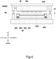
- the lower die 52 of each molding die 5a, 5b has a cavity 52C that accommodates an electronic component Wx fixed to a substrate W and resin material J.
- the lower die 52 has a bottom surface member 521 that forms the bottom surface of the cavity 52C and a side surface member 522 that surrounds the bottom surface member 521.
- the cavity 52C is formed by an upper surface of the bottom surface member 521 and an inner circumferential surface of the side surface member 522.
- the side surface member 522 is provided so as to be movable up and down relative to the bottom surface member 521.
- the side surface member 522 is supported by a plurality of elastic members 524, which may be coil springs or the like, with respect to a base plate 523 of the lower die 52.
- the lower die 52 of the present embodiment is covered with a die release film F to improve the ability of the resin molded product P to be released from the die.
- An air vent (not shown) may also be provided on the upper surface of the side surface member 522 (the contact surface between the side surface member 522 and the substrate W) to exhaust air or gas.
- a sealing structure 50 (not shown in FIGs 2 and 5 ) is be provided around the upper die 51 and lower die 52 and consists of side wall portions and sealing members such as O-rings or the like to draw a vacuum around the molding dies 5a and 5b during resin molding.
- each of the side wall members 61, 62 fix the fixed platen 2 at a predetermined height relative to a base member 101, and also support the intermediate plate 4 so that it is slidable.
- the upper end section of each of the side wall members 61, 62 is connected to the fixed platen 2
- the lower end sections of the side wall members 61, 62 are connected to the base member 101.
- each of the side wall members 61, 62 takes the form of a vertically elongated flat plate extending in the up-and-down direction.
- the slide mechanisms 7 causes linear movement of the intermediate plate 4 along the up-and-down direction with respect to the pair of side wall members 61, 62.
- the slide mechanism 7 has one or more linear motion rails 71 that extend in a straight line and one or more linear motion blocks 72 that slide on said linear motion rail 71.
- side surface plates 41 which have a flat plate shape, are connected to both the left and right side of the intermediate plate 4, the linear motion blocks 72 are provided on said side surface plates 41, and the linear motion rails 71 are provided along the inner surfaces of side wall members 61 and 62 along the up-and-down direction (the vertical direction).
- linear motion rails 71 are provided on the inner surface of each side wall member 61, 62 in parallel towards the front and rear, and linear motion blocks 72 corresponding to the two linear motion rails 71 are provided in two rows on each side surface plate 41.
- a row of linear motion blocks 72 on each side surface plate 41 is configured to have two linear motion blocks 72 (see FIG 2 ). In other words, a total of four linear motion blocks 72 are provided to each side surface plate 41.
- two linear motion rails 71 are provided on the inner surface of each side wall member 61, 62.
- the two linear motion rails 71 extend in an up-and-down direction (vertical direction).
- the two linear motion rails 71 are arranged so as to be lined up in a front-to-rear direction.
- the linear motion blocks 72 are provided on each side surface plate 41.
- the linear motion blocks 72 are arranged so as to line up in two rows in the front-to-rear direction on each side surface plate 41, so as to correspond to the two linear motion rails 71.
- the linear motion blocks 72 are arranged on each side surface plate 41, with two in each row in the up-and-down direction (vertical direction). In other words, a total of four linear motion blocks 72 are provided to each side surface plate 41.
- the raising-and-lowering linking mechanism 8 synchronizes the mold clamping and mold opening of the first molding die 5a and the second molding die 5b by causing the raising and lowering of the intermediate plate 4 to occur together with the raising and lowering of the movable platen 3.
- the raising-and-lowering linking mechanism 8 allows for simultaneous clamping of the molding dies while causing the mold clamping speed of the first molding die 5a and the mold clamping speed of the second molding die 5b to be the same.
- the raising-and-lowering linking mechanism 8 has a pantograph mechanism 81 that extends and contracts as the movable platen 3 is raised and lowered, and a coupling mechanism 82 that couples a cross link part 811 of the pantograph mechanism 81 and the intermediate plate 4.
- a pantograph mechanism 81 is arranged on each of the left and right exterior sides of the pair of side wall members 61, 62.
- the raising and lowering of the movable platen 3 and the intermediate plate 4 is made to occur together due to the two pantograph mechanisms 81 on the left and right.
- the configurations of the left and right pantograph mechanisms 81 are identical to each other.
- each pantograph mechanism 81 has a configuration including one cross link part 811, as well as an upper end link part 812 and a lower end link part 813.
- the cross link part 811 consists of a first link 81a and a second link 81b that intersect each other at their center portion, and their intersecting portions are rotatably connected by a rotary shaft 81c.
- the upper end link part 812 is such that the lower end section of each of a third link 81d and a fourth link 81e are rotatably connected to the upper end section of each of the first link 81a and second link 81b by a rotary shaft 81f, respectively, and the upper end section of each of the third link 81d and the fourth link 81e are rotatably connected to each other by a rotary shaft 81g.
- the lower end link part 813 is such that the upper end section of each of a fifth link 81h and a sixth link 81i are rotatably connected to the lower end section of each of the first link 81a and second link 81b by a rotary shaft 81j, respectively, and the lower end section of each of the fifth link 81h and the sixth link 81i are rotatably connected to each other by a rotary shaft 81k.
- the upper end section of the pantograph mechanism 81 (the upper end link part 812) is fixed to the upper end section of the side wall members 61, 62, and the lower end section of the pantograph mechanism 81 (the lower end link part 813) is fixed to the fixing member 31 that moves with the movable platen 3. Therefore, the lower end section of the pantograph mechanism 81 (the lower end link part 813) is connected to the movable platen 3 via the fixing member 31 and moves in accordance with the movement of the movable platen 3.
- the rotary shaft 81c of the cross link part 811, the rotary shaft 81g of the upper end link part 812, and the rotary shaft 81k of the lower end link part 813 of the pantograph mechanism 81 are arranged along the up-and-down direction (the vertical direction), and are located in the center portion in the width direction of the side wall members 61, 62 in the side view.
- the coupling mechanism 82 couples the cross link part 811 of the pantograph mechanism 81 and the intermediate plate 4.
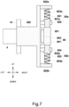
- the coupling mechanism 82 has a connecting member 821 connected to the cross link part 811, a coupling member 822 that couples the connecting member 821 to the intermediate plate 4, and elastic members 823a, 823b that are interposed between the connecting member 821 and the coupling member 822.
- the configurations of the left and right linking mechanism 82 are identical to each other.
- the connecting member 821 is connected to the cross link part 811 without interfering with the extension and contraction of the pantograph mechanism 81.
- the connecting member 821 has a long rectangular shape, and its center portion is connected to the rotary shaft 81c of the cross link part 811.
- the connecting member 821 is provided so as to extend in the front-to-rear direction (the horizontal direction).
- the coupling member 822 couples the connecting member 821 to the intermediate plate 4, and in the present embodiment is respectively connected to the side surface plates 41 connected to each of both lateral sides (here, the left and the right sides) of the intermediate plate 4 (see FIG 2 ).
- the coupling member 822 extends to an exterior side from the front and rear of the side wall members 61, 62 (see FIG 5 ).
- the elastic members 823a, 823b include an upper side elastic member 823a that absorbs upward displacement of the intermediate plate 4 relative to the connecting member 821 and a lower side elastic member 823b that absorbs downward displacement relative to the connecting member 821.
- these elastic members 823a, 823b are components of displacement absorbing mechanisms 83a, 83b provided to the coupling member 822.
- the displacement absorbing mechanisms 83a, 83b are respectively provided on the upper side and the lower side of the connecting member 821 in the coupling member 822.
- the displacement absorbing mechanism 83a on the upper side has an upper side contact part 831 that contacts the upper surface of the connecting member 821, an upper side elastic member 823a that applies force to (biases) said upper side contact part 831 toward the upper surface of the connecting member 821, and an upper side support part 832 that supports the upper side contact part 831 so as to be movable in an upward direction.
- the displacement absorbing mechanisms 83b on the lower side has a lower side contact part 833 that contacts the lower surface of the connecting member 821, a lower side elastic member 823b that applies force to (biases) said lower side contact part 833 toward the lower surface of the connecting member 821, and a lower side support part 834 that supports the lower side contact part 833 so as to be movable in a downward direction.
- the upper side support part 832 and the lower side support part 834 are fixed to the coupling member 822.
- the upper side contact part 831 is formed with an upper side stopper 831a that protrudes around its circumference so as to be able to contact the upper surface of the upper side support part 832 and limit downward movement.
- the lower side contact part 833 is formed with a lower side stopper 833a that protrudes around its circumference so as to be able to contact the lower surface of the lower side support part 834 and limit upward movement.
- the coupling member 822 has an upper side protruding portion 822a that protrudes to form an opposing surface on the upper side of the upper end surface of the upper side contact part 831 and a lower side protruding portion 822b that protrudes to form an opposing surface on the lower side of a lower end surface of the lower side contact part 831.
- a gap is provided between the upper end surface of the upper side contact part 831 and the lower surface of the upper side protruding portion 822a of the coupling member 822 (the opposing surface to the upper end surface of the upper side contact part 831) that is large enough that they do not make contact with one another due to the operation of the displacement absorbing mechanisms 83a, 83b as described below.
- a gap is also provided between the lower end surface of the lower side contact part 833 and the upper surface of the lower side protruding portion 822b of the coupling member 822 (the opposing surface to the lower end surface of the lower side contact part 833) that is large enough that they do not make contact with one another due to the operation of the displacement absorbing mechanisms 83a, 83b as described below.
- the elastic member 823a is such that its upper end contacts the lower surface of the upper side protruding portion 822a of the coupling member 822 (the opposing surface to the upper end surface of the upper side contact part 831), its lower end contacts the upper surface of the upper side stopper 831a of the upper side contact part 831, and it is in a state of not being expanded or contracted.
- the elastic member 823b is such that its upper end contacts the lower surface of the lower side stopper 833a of the lower side contact part 833, its lower end contacts the upper surface of the lower side protruding portion 822b of the coupling member 822 (the opposing surface to the lower end surface of the lower side contact part 833), and it is in a state of not being expanded or contracted.
- the resin molding apparatus 100 of the present embodiment is further provided with a guide mechanism 84 interposed between the connecting member 821 and the coupling member 822.
- the guide mechanism 84 guides the movement of the connecting member 821 and the coupling member 822 when they move relative to each other.
- the guide mechanism 84 guides the movement in the up-and-down direction of the connecting member 821 and is provided between the opposing surfaces of the connecting member 821 and the coupling member 822.
- the guide mechanism 84 has a linear motion rail 841 provided on one of either the connecting member 821 or the coupling member 822 and a linear motion block 842 provided on the other of the connecting member 821 or the coupling member 822.
- the linear motion rail 841 is provided on the coupling member 822 and the linear motion block 842 is provided on the connecting member 821.
- control unit COM is a dedicated or general-purpose computer with a CPU, internal memory, input/output interface, AD converter, etc.
- the substrate W is conveyed and held in the upper die 51 of each molding die 5a, 5b by the substrate supplying and storing module A shown in FIG 1 .
- the resin material J is contained in the cavity 52C of the lower die 52 of each molding die 5a, 5b by the resin material supply module C. In this way, the substrate W, which is the object-to-be-molded, and resin material J are supplied to each molding die 5a, 5b
- the movable platen 3 is raised by the drive mechanism 10.
- the pantograph mechanism 81 contracts as the movable platen 3 is raised, and the intermediate plate 4 connected to the rotary shaft 81c of the cross link part 811 of the pantograph mechanism 81 rises.
- the sealing structure 50 shown in FIG 5 seals the circumference around the molding dies 5a, 5b, and a vacuum pump, not shown, draws a vacuum around the molding dies 5a, 5b.
- the upper surface of the lower die 52 of each molding die 5a, 5b contacts the substrate W held by suction to the upper die 51.
- the upper side elastic member 823a or the lower side elastic member 823b will deform before the elastic member 524 of the lower die 52.
- the spring constants of the upper side elastic member 823a and the lower side elastic member 823b are smaller than the spring constant of the elastic member 524 of the lower die 52.
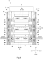
- the intermediate plate 4 (lower die 52 of the first molding die 5a) makes contact with the substrate W held by suction to the corresponding upper die 51 before the lower die 52 atop the movable platen 3 (the lower die 52 of the second molding die 5b), the intermediate plate 4 is displaced downward with respect to the connecting member 821 and the upper side elastic member 823a contracts (see FIG 8(a) ).
- the upper side elastic member 823a and lower side elastic member 823b absorb not only variations in the thickness of the substrate W, but also variations in the amount of resin material J contained in the cavity 52C, variations in the volume of the electronic components Wx fixed to the substrate W, and so on.
- the drive mechanism 10 then further raises the movable platen 3 to complete the mold clamping of the first molding die 5a and the second molding die 5b, and resin molding is completed by maintaining this state for a predetermined time (for example, the curing time of resin material J). In this way, each molding die 5a, 5b is clamped using the raising-and-lowering linking mechanism 8, and resin molding is performed.
- the drive mechanism 10 then lowers the movable platen 3, causing each molding die 5a, 5b to open.
- the resin molded product P is then stored in the substrate storage part 12 by the substrate supplying and storing module A (see FIG 1 ).
- each molding die 5a, 5b is opened using the raising-and-lowering linking mechanism 8, and the substrate W that is the object-to-be-molded that has been resin molded (resin molded product P) is removed from each molding die 5a, 5b and stored in the substrate storage part 12, and the resin molded product P is thus manufactured.
- the coupling mechanism 82 that couples the cross link part 811 of the pantograph mechanism 81 and the intermediate plate 4, has a connecting member 821 connected to the cross link part 811, a coupling member 822 that couples the connecting member 821 to the intermediate plate 4, and elastic members 823a, 823b interposed between the connecting member 821 and the coupling member 822, so that variations in the thickness and the like of the substrate W in each molding die 5a and 5b can be absorbed.
- the molds can be clamped while absorbing such variations in the thickness or the like of the substrate W thanks to the elastic deformation of the elastic members 823a, 823b.
- the resin molding apparatus 100 that clamps a plurality of molding dies 5a, 5b it is possible to, while synchronizing the clamping of the plurality of molding dies 5a, 5b, absorb variations in the thickness, etc., of the object-to-be-molded in each molding die and perform resin molding.
- the resin molding apparatus 100 according the second embodiment differs from that of the first embodiment (which is a configuration with two sets of molding dies using one intermediate plate 4) in that it is configured to have a plurality of sets of molding dies using a plurality of intermediate plates 4.
- it may be configured to have three sets of molding dies using two intermediate plates 4, to have four sets of molding dies using three intermediate plates 4, to have five sets of molding dies using four intermediate plates 4, or to have six or more molding dies using five or more intermediate plates 4.
- a plurality of intermediate plates 4 are arranged along the up-and-down direction between the fixed platen 2 and the movable platen 3.
- Molding dies 5b, 5c which include an upper die 51 and a lower die 52, are respectively provided between the plurality of intermediate plates 4.
- FIG 8 the configuration from the fixed platen 2 up until three intermediate plates 4 is shown, and the lower part is omitted.
- Each of the plurality of intermediate plates 4 is connected to each of the plurality of cross link parts 811 of the pantograph mechanism 81 via a coupling mechanism 82, as in the first embodiment described above. As a result, the raising and lowering of the plurality of intermediate plates 4 is made to occur together with the raising and lowering of the movable platen 3.
- the pantograph mechanism 81 is configured to have a plurality of cross link parts 811 of a number corresponding to the number of the plurality of intermediate plates 4, as well as an upper end link part 812 and a lower end link part 813.
- the plurality of cross link parts 811 are connected in series.
- the upper end section of the first link 81a of one cross link part 811 is rotatably connected to the upper end section of the second link 81b of the other cross link part 811 by a rotary shaft 811
- the upper end section of the second link 81b of one cross link part 811 is rotatably connected to the upper end section of the first link 81a of the other cross link part 811 by a rotary shaft 81m.
- the configuration of the upper end link part 812 and the lower end link part 813 is the same as in the first embodiment.
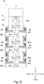
- the side surface plates 41 connected to each of the plurality of intermediate plates 4 are displaced in the horizontal direction so as not to interfere with each other.
- the side surface plates 41 of adjacent intermediate plate 4 in the up-and-down direction are arranged so that they are displaced to the left and right (in the horizontal direction) and so as to alternate.
- the side surface plate 41a of the first intermediate plate 4 from the top is positioned on the inner side and the side surface plate 41b of the second intermediate plate 4 from the top is positioned on the exterior side.
- the side surface plate 41b of the second intermediate plate 4 from the top is positioned on the exterior side and the side surface plate 41c of the third intermediate plate 4 from the top is positioned on the inner side.
- the side surface plate 41b of the second intermediate plate 4 from the top does not impede the movement of the linear motion blocks 842 located on the side surface plates 41a, 41c (first from the top and third from the top) located on the inner side, a through hole or notch or the like not shown in the figures is formed over the range of movement of said linear motion blocks 842.
- resin molding can be performed using three or more molding dies 5a - 5c, thereby improving the productivity of manufacturing the resin molded products P.
- the side surface plates 41 of the plurality of intermediate plates 4 are arranged so as to be displaced in the horizontal direction so that they do not interfere with each other, thereby allowing the height dimension of the resin molding apparatus 100 to be reduced.
- the present invention is not limited to the aforementioned embodiments.
- the above embodiments were configured such that the coupling member 822 extends outward from the front and rear of the side wall members 61, 62, but as shown in FIG 11 , the coupling member 822 and the connecting member 821 may be configured to be connected through a through portion 6H formed in the side wall members 61, 62.
- a through portion 6H is formed in the side wall members 61, 62 corresponding to the cross link part 811.
- the through portion 6H is formed so that it does not interfere with the movement of the coupling member 822, taking into account the extent to which the intermediate plate 4 moves.
- the coupling member 822 is connected to the side surface plate 41 of the intermediate plate 4 and extends outward from the side wall members 61, 62 through the through portion 6H of the side wall members 61, 62 to support the elastic members 823a, 823b (the displacement absorbing mechanisms 83a, 83b) on the exterior side of the side wall members 61, 62.
- the elastic members 823a, 823b (displacement absorbing mechanisms 83a, 83b) couple the coupling member 822 to the connecting member 821.
- a guide mechanism 84 is provided between the connecting member 821 and the coupling member 822.
- the guide mechanism 84 has a linear motion rail 841 provided on one of the connecting member 821 or the coupling member 822 and a linear motion block 842 provided on the other of the connecting member 821 or the coupling member 822.
- the plurality of molding dies used in the first and second embodiments described above may be the same molding dies or different molding dies from each other.
- the upper dies may be different from each other and the lower dies may be different from each other.
- the linear motion rails 71 of the slide mechanism 7 are provided on side wall members 61, 62, and the linear motion blocks 72 are provided on the side surface plate 41, but it is also possible for the linear motion rails 71 of the slide mechanism 7 to be installed on the side surface plate 41 and the linear motion block 72 on the side wall members 61, 62.
- the present invention configured in this manner, in a resin molding apparatus that clamps a plurality of molding dies, it is possible to, while synchronizing the clamping of the plurality of molding dies, absorb variations in the thickness, etc., of the object-to-be-molded in each molding die and perform resin molding.
Landscapes
- Engineering & Computer Science (AREA)
- Mechanical Engineering (AREA)
- Moulds For Moulding Plastics Or The Like (AREA)
- Casting Or Compression Moulding Of Plastics Or The Like (AREA)
- Injection Moulding Of Plastics Or The Like (AREA)
Abstract
Description
- The present invention relates to a resin molding apparatus and a resin molded product manufacturing method.
- Conventionally, as disclosed in Patent Document 1, in a manufacturing apparatus for manufacturing synthetic resin molded bodies that includes a fixed lower die, an upper die that can be raised and lowered above the lower die, and a frame that supports an intermediate die arranged between the lower die and the upper die, it has been considered to connect the upper die, intermediate die, and lower die with a pantograph mechanism so that molding of a molded body by the upper die and intermediate die and molding of a molded body by the intermediate die and lower die is carried out simultaneously.
- [Patent Document 1]
Japanese Utility Model Application Publication No. S63-161708 - However, the above-mentioned manufacturing apparatus does not take into consideration variations in thickness between molded bodies that are resin-molded by the upper die and the intermediate die and molded bodies that are resin-molded by the intermediate die and the lower die. Moreover, when resin molding is performed on an object-to-be-molded such as a substrate, variations in the thickness of the object-to-be-molded can end up causing variations in the quality or the like of resin molded products that have been resin molded by the respective molding dies.
- The present invention has been developed in view of the above-mentioned problems, and its main object is to provide a resin molding apparatus that clamps a plurality of molding dies that, while synchronizing the clamping of the plurality of molding dies, absorbs variations in the thickness, etc., of the object-to-be-molded in each molding die and performs resin molding.
- A resin molding apparatus according to the present invention is characterized by comprising: a fixed platen; a movable platen that can be raised and lowered by a drive mechanism; an intermediate plate arranged between the fixed platen and the movable platen; molding dies, each including an upper die and a lower die, one of the molding dies being provided between the fixed platen and the intermediate plate and another of the molding dies being provided between the intermediate plate and the movable platen; a pair of side wall members arranged on both lateral sides of the movable platen and the intermediate plate; a slide mechanism that causes the intermediate plate to slide with respect to the pair of side wall members; and a raising-and-lowering linking mechanism that causes the raising and lowering of the intermediate plate to occur together with the raising and lowering of the movable platen; wherein the raising-and-lowering linking mechanism comprises a pantograph mechanism that extends and contracts due to the raising and lowering of the movable platen, and a coupling mechanism that couples a cross link part of the pantograph mechanism and the intermediate plate; and the coupling mechanism has a connecting member connected to the cross link part; a coupling member that couples the connecting member to the intermediate plate; and an elastic member interposed between the connecting member and the coupling member.
- According to the present invention configured in this manner, in a resin molding apparatus that clamps a plurality of molding dies, it is possible to, while synchronizing the clamping of the plurality of molding dies, absorb variations in the thickness, etc., of the object-to-be-molded in each molding die and perform resin molding.
-
-
FIG 1 : A diagram schematically showing a configuration of a resin molding apparatus according to a first embodiment of the present invention. -
FIG 2 : A front view schematically showing a configuration of the resin molding apparatus of the first embodiment. -
FIG 3 : A side view schematically showing a configuration of the resin molding apparatus according to the first embodiment. -
FIG 4 : A diagram schematically showing a configuration of a molding die according to the first embodiment. -
FIG 5 : An enlarged cross-sectional view schematically showing a peripheral structure of a side wall member according to the first embodiment. -
FIG 6 : An enlarged view schematically showing a pantograph mechanism according to the first embodiment. -
FIG 7 : An enlarged cross-sectional view schematically showing a peripheral structure of an elastic member of the first embodiment. -
FIG 8 : A cross-sectional view schematically showing the operation of the elastic member of the first embodiment. -
FIG 9 : A front view schematically showing a configuration of a resin molding apparatus according to a second embodiment. -
FIG 10 : A side view schematically showing a configuration of the resin molding apparatus according to the second embodiment. -
FIG 11 : A side view, a cross-sectional view, and a front view schematically showing a peripheral structure of an elastic member according to a variation embodiment. - Next, making reference to examples, the aspects of the present invention will be described in greater detail. However, the present invention is not limited by the aspects as described below.
- A resin molding apparatus according to a first aspect of the present invention is characterized by comprising: a fixed platen; a movable platen that can be raised and lowered by a drive mechanism; an intermediate plate arranged between the fixed platen and the movable platen; molding dies, each including an upper die and a lower die, one of the molding dies being provided between the fixed platen and the intermediate plate and another of the molding dies being provided between the intermediate plate and the movable platen; a pair of side wall members arranged on both lateral sides of the movable platen and the intermediate plate; a slide mechanism that causes the intermediate plate to slide with respect to the pair of side wall members; and a raising-and-lowering linking mechanism that causes the raising and lowering of the intermediate plate to occur together with the raising and lowering of the movable platen; wherein the raising-and-lowering linking mechanism comprises a pantograph mechanism that extends and contracts due to the raising and lowering of the movable platen, and a coupling mechanism that couples a cross link part of the pantograph mechanism and the intermediate plate; and the coupling mechanism has a connecting member connected to the cross link part; a coupling member that couples the connecting member to the intermediate plate; and an elastic member interposed between the connecting member and the coupling member.
- In a resin molding apparatus configured as such, the coupling mechanism that couples the cross link part of the pantograph mechanism and the intermediate plate has a connecting member connected to the cross link part, a coupling member that couples the connecting member to the intermediate plate, and an elastic member interposed between the connecting member and the coupling member, so that the clamping of a plurality of molding dies can be synchronized while absorbing variations in the thickness of the object-to-be-molded in each molding die.
- For example, even if the thickness of the object-to-be-molded in the molding die on one side of the intermediate plate and the thickness of the object-to-be-molded in the molding die on the other side of the intermediate plate are different, the elastic members can be elastically deformed to absorb any variation in the thickness of the object-to-be-molded and the mold can be clamped. As a result, in a resin molding apparatus that clamps a plurality of molding dies, it is possible to, while synchronizing the clamping of the plurality of molding dies, absorb variations in the thickness of the object-to-be-molded in each molding die and perform resin molding.
- Since the raising and lowering of the movable platen and the raising and lowering of the intermediate plate are made to occur together using the pantograph mechanism, it is possible to avoid a situation in which each component must be enlarged as well as avoid the need to increase the size of the entire apparatus, and highly rigid components are also made to be unnecessary.
- The resin molding apparatus according to a second aspect of the present invention is one characterized in that, in addition to the configuration of the first aspect described above, a plurality of the intermediate plates are arranged along an up-and-down direction between the fixed platen and the movable platen; and one of the molding dies including the upper die and the lower die is provided between each of the plurality of intermediate plates.
- With this configuration, the number of molding dies can be increased, thereby improving the productivity of manufacturing the resin molded products. Since the raising and lowering of the plurality of intermediate plates is made to occur together with the raising and lowering of the movable platen via the pantograph mechanism, even in a configuration in which molding dies are provided between each of a plurality of intermediate plates, it is possible to avoid a situation in which each component must be enlarged as well as avoid the need to increase the size of the entire apparatus, and highly rigid components are also made to be unnecessary.
- A resin molding apparatus according to a third aspect of the present invention is one characterized in that, in addition to the configuration of the first or second aspect, the pantograph mechanism is provided on an exterior side of the side wall members; the coupling member extends to the exterior side of the side wall members; and the elastic member is provided on the exterior side of the side wall members.
- Configured like this, since the pantograph mechanism is provided exterior to the side wall members and the elastic member is provided exterior to the side wall members, the number of members provided between the pair of side wall members can be reduced and the configuration simplified. The size of the intermediate plate arranged between the pair of side wall members can also be increased without being restricted by the pantograph mechanisms, elastic members, etc., thus increasing the size of molding dies attached to the intermediate plate and increasing the potential varieties of the molding dies.
- A resin molding apparatus according to a fourth aspect of the present invention is one characterized in that, in addition to the configuration of any one of the first to the third aspects, the elastic member has a lower side elastic member that absorbs a downward displacement of the intermediate plate relative to the connecting member and an upper side elastic member that absorbs an upward displacement of the intermediate plate relative to the connecting member.
- With this configuration, if the thickness of the object-to-be-molded in the molding die on one side of the intermediate plate (the upper surface side) is greater than the thickness of the object-to-be-molded in the molding die on the other side of the intermediate plate (the lower surface side), the lower side elastic member absorbs the variation in their thickness. On the other hand, if the thickness of the object-to-be-molded in the molding die on the other side of the intermediate plate (the lower surface side) is greater than the thickness of the object-to-be-molded in the molding die on one side of the intermediate plate (the upper surface side), the upper side elastic member absorbs the variation in their thickness.
- A resin molding apparatus according to a fifth aspect of the present invention is one characterized in that, in addition to the configuration of any one of the first to the fourth aspects, the slide mechanism has a linear motion rail and a linear motion block that slides on said linear motion rail.
- With this configuration, the extent to which the intermediate plate and movable platen are parallel to the fixed platen, as well as the extent to which the upper die and lower die of each molding die are parallel, can be maintained with high accuracy.
- A resin molding apparatus according to a sixth aspect of the present invention is one characterized in that, in addition to the configuration of the fifth aspect, a side surface plate is connected to each of both lateral sides of the intermediate plate, the linear motion block is provided on one of the side surface plate or the side wall member, and the linear motion rail is provided on the other of the side surface plate or the side wall member.
- Configured like this, the linear motion block or the linear motion rail is arranged on the side surface plate connected to the intermediate plate, so by making the up-and-down direction dimension of the side surface plate larger than the up-and-down direction dimension (thickness dimension) of the intermediate plate, the linear motion block or linear motion rail can be provided without regard to the thickness dimension of the intermediate plate.
- A resin molding apparatus according to a seventh aspect of the present invention is one characterized in that, in addition to the configuration of the fifth or the sixth aspect, a side surface plate is connected to each of both lateral sides of the intermediate plate, the linear motion block is provided on the side surface plate, and the linear motion rail is provided on an inner surface of the side wall member.
- Configured like this, the linear motion block is arranged on the side surface plate connected to the intermediate plate, so by making the up-and-down direction dimension of the side surface plate larger than the up-and-down direction dimension (thickness dimension) of the intermediate plate, the linear motion block can be provided without regard to the thickness dimension of the intermediate plate. Moreover, since the linear motion rail is arranged on the inner surface of the side wall member, the linear motion rail of the raising-and-lowering platen and the linear motion rail of the intermediate plate can be the same one, simplifying the configuration.
- A resin molding apparatus according to an eighth aspect of the present invention is one characterized in that, in addition to the configuration of the seventh aspect, two of the linear motion rails are provided on the inner surface of the side wall member, and two rows of the linear motion blocks are provided on the side surface plate corresponding to the two linear motion rails.
- With this configuration, the extent to which the intermediate plate and movable platen are parallel to the fixed platen, as well as the extent to which the upper die and lower die of each molding die are parallel, can be maintained with even higher accuracy.
- A resin molding apparatus according to a ninth aspect of the present invention is one characterized in that, in addition to the configuration of any one of the sixth to the eighth aspect, in a configuration having a plurality of the intermediate plates, the side surface plates respectively connected to the plurality of intermediate plates are displaced in a horizontal direction so as not to interfere with each other.
- With this configuration, the side surface plates of each intermediate plate do not interfere with each other when the plurality of intermediate plates are raised and lowered, thus reducing the height dimension of the resin molding apparatus. That is, if the side surface plates of each intermediate plate were not displaced in the horizontal direction, the side surface plates would have to be placed with enough room in the up-and-down direction to prevent interference, which would increases the height dimension of the resin molding apparatus.
- A resin molding apparatus according to a tenth aspect of the present invention is one characterized in that, in addition to the configuration of any one of the first to the ninth aspect, it further comprises a guide mechanism interposed between the connecting member and either the coupling member or the side wall member, and in that the guide mechanism has a linear motion rail provided on one of (i) the connecting member or (ii) either of the coupling member or the side wall member and a linear motion block provided on the other of (i) the connecting member or (ii) either of the coupling member or the side wall member.
- With this configuration, the connecting member connected to the cross link part of the pantograph mechanism can be raised and lowered in a stable manner.
- A resin molded product manufacturing method for manufacturing a resin molded product that is an aspect of the present invention is one using the resin molding apparatus according to any one of the first to tenth aspects, and includes a resin molding process in which, in a state in which an object-to-be-molded and a resin material have been supplied to the molding dies, the molding dies are clamped and resin molding is performed using the raising-and-lowering linking mechanism and a removal process in which the molding dies are opened using the raising-and-lowering linking mechanism and the object-to-be-molded that has been resin-molded is removed from the mold.
- A first embodiment of a resin molding apparatus according to the present invention will be described below with reference to the drawings. Moreover, for ease of understanding, each of the drawings shown below are drawn schematically with some parts omitted or exaggerated where appropriate. The same components are denoted by the same reference numerals and the description thereof will be omitted as appropriate.
- The
resin molding apparatus 100 according the first embodiment is one that manufactures resin molded products P by resin sealing an electronic component Wx fixed on a substrate W, which is the object-to-be-molded, via resin molding using a resin material J. Examples of the substrate include a metal substrate, a resin substrate, a glass substrate, a ceramic substrate, a circuit board, a semiconductor substrate, a lead frame, a silicon wafer, and a glass wafer. Examples of the resin material J include powdered resin (including a granular resin), liquid resin, and so on. Examples of the electronic component Wx include electronic elements such as semiconductor chips, resistor elements, or capacitor elements, or also an electronic component formed by sealing at least one of said electronic elements with resin. - As shown in
FIG 1 , theresin molding apparatus 100 includes a substrate supplying and storing module A, two resin molding modules B, and a resin material supply module C as its respective components. Each of the components (each module A to C) is detachable and replaceable with respect to the other components. - The substrate supplying and storing module A has a
substrate receiving unit 11 that receives substrates W that have not yet been molded from an exterior, asubstrate storage unit 12 that stores substrates W that have been molded (resin molded products P), a conveyingmechanism 13 that conveys substrates W that have not yet been molded and resin molded products P, and atransfer mechanism 14, such as a conveyance robot, that transfers substrates W that have not yet been molded and resin molded products P to the conveyingmechanism 13. - The conveying
mechanism 13 conveys a substrate W that has not yet been molded from the substrate supplying and storing module A to the resin molding module B and, in the resin molding module B, supplies the substrate W that has not yet been molded to the molding dies 5a, 5b. After said substrate W is resin molded, the conveyingmechanism 13 receives the resin molded product P, which is the substrate W after having been resin molded, from the molding dies 5a, 5b in the resin molding module B and conveys it to the substrate supplying and storing module A. In addition, thetransfer mechanism 14 transfers the substrate W that has not yet been molded from thesubstrate receiving unit 11 to the conveyingmechanism 13, and transfers the resin molded product P from the conveyingmechanism 13 to thesubstrate storage unit 12. - Each resin molding module B has an
upper die 51 which is a first die that holds the substrate W, and alower die 52 which is a second die in which acavity 52C is formed, and by clamping these together, the electronic component Wx fixed to the substrate W is resin-sealed by resin molding using a resin material J. The specific configuration of the resin molding module B will be described later. - The resin material supply module C has a moving table 15, a resin
material accommodation unit 16 placed on the moving table 15, a resinmaterial providing mechanism 17 that measures and provides resin material J to the resinmaterial accommodation unit 16, and a resinmaterial supply mechanism 18 that transports the resinmaterial accommodation unit 16 and supplies resin material J to thecavity 52C of thelower die 52. - In the resin material supply module C, the moving table 15 moves between a resin providing position where the resin
material providing mechanism 17 provides resin material and a transfer position for transferring the resinmaterial accommodation unit 16 to the resinmaterial supply mechanism 18. The resinmaterial supply mechanism 18 transports the resinmaterial accommodation unit 16, which contains resin material J, from the resin material supply module C to the resin molding module B, and supplies resin material J to the molding dies 5a and 5b in the resin molding module B. The resinmaterial supply mechanism 18 then conveys the resinmaterial accommodation unit 16, after it has supplied the resin material J, from the resin molding module B to the resin material supply module C. - As shown in
FIGs 2 and3 , the resin molding module B includes a fixedplaten 2; amovable platen 3 that can be raised and lowered by adrive mechanism 10; anintermediate plate 4 arranged between the fixedplaten 2 and themovable platen 3; a first molding die 5a and a second molding die 5b each including anupper die 51 and alower die 52, respectively provided between the fixedplaten 2 and theintermediate plate 4 and between theintermediate plate 4 and themovable platen 3; a pair ofside wall members movable platen 3 andintermediate plate 4; aslide mechanism 7 that causes theintermediate plate 4 to slide with respect to the pair ofside wall members linking mechanism 8 that causes the raising and lowering of theintermediate plate 4 to occur together with the raising and lowering of themovable platen 3. - The upper die 51 of the
first molding die 5a is removably attached to the lower surface of the fixedplaten 2 directly or via another component. Also, the pair ofside wall members platen 2. It is also possible for the pair ofside wall members platen 2. The fixedplaten 2 of the present embodiment takes the form of a flat plate that is roughly rectangular in plan view. - The
lower die 52 of thesecond molding die 5b is removably attached to the upper surface of themovable platen 3 directly or via another component. Themovable platen 3 is raised and lowered by thedrive mechanism 10 provided below themovable platen 3. Themovable platen 3 of the present embodiment takes the form of a flat plate that is roughly rectangular in plan view. A fixingmember 31 is connected to themovable platen 3, and a lower end section (lower end link part 813) of thepantograph mechanism 81, described below, is fixed to the fixingmember 31. - The
drive mechanism 10 of the present embodiment is a linear motion system that raises and lowers the movable platen using a ball screw mechanism that converts rotation of a servomotor or the like into linear movement, but it may also be a link system that transmits power from a power source such as a servomotor to the movable platen using a link mechanism such as a toggle link, for example. - The
lower die 52 of thefirst molding die 5a is removably attached to the upper surface of theintermediate plate 4 directly or via another component. The upper die 51 of thesecond molding die 5b is removably attached to the lower surface of theintermediate plate 4 directly or via another component. Theintermediate plate 4 of the present embodiment takes the form of a flat plate that is roughly rectangular in plan view. - Next, the first molding die 5a and
second molding die 5b will be described with reference toFIG 4 . - The upper die 51 of each molding die 5a, 5b holds the back surface of the substrate W by suction. A suction opening (not shown) is formed on the lower surface of the
upper die 51, and a suction channel (not shown) leading to the suction opening is formed within theupper die 51. The suction channel is connected to an external suction apparatus (not shown) - The
lower die 52 of each molding die 5a, 5b has acavity 52C that accommodates an electronic component Wx fixed to a substrate W and resin material J. Specifically, thelower die 52 has abottom surface member 521 that forms the bottom surface of thecavity 52C and aside surface member 522 that surrounds thebottom surface member 521. Thecavity 52C is formed by an upper surface of thebottom surface member 521 and an inner circumferential surface of theside surface member 522. Theside surface member 522 is provided so as to be movable up and down relative to thebottom surface member 521. Specifically, theside surface member 522 is supported by a plurality ofelastic members 524, which may be coil springs or the like, with respect to abase plate 523 of thelower die 52. Furthermore, thelower die 52 of the present embodiment is covered with a die release film F to improve the ability of the resin molded product P to be released from the die. An air vent (not shown) may also be provided on the upper surface of the side surface member 522 (the contact surface between theside surface member 522 and the substrate W) to exhaust air or gas. Besides this, a sealing structure 50 (not shown inFIGs 2 and5 ) is be provided around theupper die 51 andlower die 52 and consists of side wall portions and sealing members such as O-rings or the like to draw a vacuum around the molding dies 5a and 5b during resin molding. - As shown in
FIGs 2 and3 , the pair ofside wall members platen 2 at a predetermined height relative to abase member 101, and also support theintermediate plate 4 so that it is slidable. Here, the upper end section of each of theside wall members platen 2, and the lower end sections of theside wall members base member 101. Moreover, in the present embodiment, each of theside wall members - The
slide mechanisms 7 causes linear movement of theintermediate plate 4 along the up-and-down direction with respect to the pair ofside wall members slide mechanism 7 has one or more linear motion rails 71 that extend in a straight line and one or more linear motion blocks 72 that slide on saidlinear motion rail 71. - In the present embodiment,
side surface plates 41, which have a flat plate shape, are connected to both the left and right side of theintermediate plate 4, the linear motion blocks 72 are provided on saidside surface plates 41, and the linear motion rails 71 are provided along the inner surfaces ofside wall members - In detail, as shown in
FIG 5 , two linear motion rails 71 are provided on the inner surface of eachside wall member side surface plate 41. Here, a row of linear motion blocks 72 on eachside surface plate 41 is configured to have two linear motion blocks 72 (seeFIG 2 ). In other words, a total of four linear motion blocks 72 are provided to eachside surface plate 41. - In detail, as shown in
FIGs 2 and5 , two linear motion rails 71 are provided on the inner surface of eachside wall member side surface plate 41. Here, the linear motion blocks 72 are arranged so as to line up in two rows in the front-to-rear direction on eachside surface plate 41, so as to correspond to the two linear motion rails 71. The linear motion blocks 72 are arranged on eachside surface plate 41, with two in each row in the up-and-down direction (vertical direction). In other words, a total of four linear motion blocks 72 are provided to eachside surface plate 41. - As shown in
FIGs 2 ,3 , and5 - 7 , the raising-and-loweringlinking mechanism 8 synchronizes the mold clamping and mold opening of the first molding die 5a and the second molding die 5b by causing the raising and lowering of theintermediate plate 4 to occur together with the raising and lowering of themovable platen 3. In other words, the raising-and-loweringlinking mechanism 8 allows for simultaneous clamping of the molding dies while causing the mold clamping speed of the first molding die 5a and the mold clamping speed of the second molding die 5b to be the same. - Specifically, the raising-and-lowering
linking mechanism 8 has apantograph mechanism 81 that extends and contracts as themovable platen 3 is raised and lowered, and acoupling mechanism 82 that couples across link part 811 of thepantograph mechanism 81 and theintermediate plate 4. - As shown in
FIG 2 , apantograph mechanism 81 is arranged on each of the left and right exterior sides of the pair ofside wall members movable platen 3 and theintermediate plate 4 is made to occur together due to the twopantograph mechanisms 81 on the left and right. Moreover, the configurations of the left andright pantograph mechanisms 81 are identical to each other. - Specifically, as shown in
FIGs 3 and6 , eachpantograph mechanism 81 has a configuration including onecross link part 811, as well as an upperend link part 812 and a lowerend link part 813. Thecross link part 811 consists of afirst link 81a and asecond link 81b that intersect each other at their center portion, and their intersecting portions are rotatably connected by arotary shaft 81c. The upperend link part 812 is such that the lower end section of each of athird link 81d and afourth link 81e are rotatably connected to the upper end section of each of thefirst link 81a andsecond link 81b by arotary shaft 81f, respectively, and the upper end section of each of thethird link 81d and thefourth link 81e are rotatably connected to each other by arotary shaft 81g. The lowerend link part 813 is such that the upper end section of each of afifth link 81h and asixth link 81i are rotatably connected to the lower end section of each of thefirst link 81a andsecond link 81b by arotary shaft 81j, respectively, and the lower end section of each of thefifth link 81h and thesixth link 81i are rotatably connected to each other by arotary shaft 81k. - The upper end section of the pantograph mechanism 81 (the upper end link part 812) is fixed to the upper end section of the
side wall members member 31 that moves with themovable platen 3. Therefore, the lower end section of the pantograph mechanism 81 (the lower end link part 813) is connected to themovable platen 3 via the fixingmember 31 and moves in accordance with the movement of themovable platen 3. In the present embodiment, as shown inFIG 6 , therotary shaft 81c of thecross link part 811, therotary shaft 81g of the upperend link part 812, and therotary shaft 81k of the lowerend link part 813 of thepantograph mechanism 81 are arranged along the up-and-down direction (the vertical direction), and are located in the center portion in the width direction of theside wall members - As shown in
FIGs 2 ,3 ,5 , and7 , thecoupling mechanism 82 couples thecross link part 811 of thepantograph mechanism 81 and theintermediate plate 4. Specifically, thecoupling mechanism 82 has a connectingmember 821 connected to thecross link part 811, acoupling member 822 that couples the connectingmember 821 to theintermediate plate 4, andelastic members member 821 and thecoupling member 822. Moreover, the configurations of the left and right linkingmechanism 82 are identical to each other. - As shown in
FIGs 3 ,5 , and6 , the connectingmember 821 is connected to thecross link part 811 without interfering with the extension and contraction of thepantograph mechanism 81. Specifically, the connectingmember 821 has a long rectangular shape, and its center portion is connected to therotary shaft 81c of thecross link part 811. The connectingmember 821 is provided so as to extend in the front-to-rear direction (the horizontal direction). - The
coupling member 822 couples the connectingmember 821 to theintermediate plate 4, and in the present embodiment is respectively connected to theside surface plates 41 connected to each of both lateral sides (here, the left and the right sides) of the intermediate plate 4 (seeFIG 2 ). Thecoupling member 822 extends to an exterior side from the front and rear of theside wall members 61, 62 (seeFIG 5 ). - The
elastic members coupling member 822 and the connectingmember 821. Theelastic members side wall members - Specifically, as shown in
FIGs 2 ,3 ,5 and7 , theelastic members elastic member 823a that absorbs upward displacement of theintermediate plate 4 relative to the connectingmember 821 and a lower sideelastic member 823b that absorbs downward displacement relative to the connectingmember 821. As shown inFIG 7 , theseelastic members displacement absorbing mechanisms coupling member 822. - The
displacement absorbing mechanisms member 821 in thecoupling member 822. Thedisplacement absorbing mechanism 83a on the upper side has an upperside contact part 831 that contacts the upper surface of the connectingmember 821, an upper sideelastic member 823a that applies force to (biases) said upperside contact part 831 toward the upper surface of the connectingmember 821, and an upperside support part 832 that supports the upperside contact part 831 so as to be movable in an upward direction. Thedisplacement absorbing mechanisms 83b on the lower side has a lowerside contact part 833 that contacts the lower surface of the connectingmember 821, a lower sideelastic member 823b that applies force to (biases) said lowerside contact part 833 toward the lower surface of the connectingmember 821, and a lowerside support part 834 that supports the lowerside contact part 833 so as to be movable in a downward direction. The upperside support part 832 and the lowerside support part 834 are fixed to thecoupling member 822. - Here, the upper
side contact part 831 is formed with anupper side stopper 831a that protrudes around its circumference so as to be able to contact the upper surface of the upperside support part 832 and limit downward movement. The lowerside contact part 833 is formed with alower side stopper 833a that protrudes around its circumference so as to be able to contact the lower surface of the lowerside support part 834 and limit upward movement. - The
coupling member 822 has an upperside protruding portion 822a that protrudes to form an opposing surface on the upper side of the upper end surface of the upperside contact part 831 and a lowerside protruding portion 822b that protrudes to form an opposing surface on the lower side of a lower end surface of the lowerside contact part 831. A gap is provided between the upper end surface of the upperside contact part 831 and the lower surface of the upperside protruding portion 822a of the coupling member 822 (the opposing surface to the upper end surface of the upper side contact part 831) that is large enough that they do not make contact with one another due to the operation of thedisplacement absorbing mechanisms side contact part 833 and the upper surface of the lowerside protruding portion 822b of the coupling member 822 (the opposing surface to the lower end surface of the lower side contact part 833) that is large enough that they do not make contact with one another due to the operation of thedisplacement absorbing mechanisms - The basic operation of the
displacement absorbing mechanisms - In the initial state of the
displacement absorbing mechanisms FIG 7 ), theelastic member 823a is such that its upper end contacts the lower surface of the upperside protruding portion 822a of the coupling member 822 (the opposing surface to the upper end surface of the upper side contact part 831), its lower end contacts the upper surface of theupper side stopper 831a of the upperside contact part 831, and it is in a state of not being expanded or contracted. Moreover, in the initial state of thedisplacement absorbing mechanisms elastic member 823b is such that its upper end contacts the lower surface of thelower side stopper 833a of the lowerside contact part 833, its lower end contacts the upper surface of the lowerside protruding portion 822b of the coupling member 822 (the opposing surface to the lower end surface of the lower side contact part 833), and it is in a state of not being expanded or contracted. - Then, as shown in
FIG 8(a) , when theintermediate plate 4 is displaced downward relative to the connectingmember 821, thecoupling member 822 connected to theintermediate plate 4 is displaced downward relative to the connectingmember 821. When this happens, with the connectingmember 821 and the upperside contact part 831 in a state of rest, the upperside support part 832 and the upperside protruding portion 822a of thecoupling member 822 are also displaced relatively downward, so that the upper sideelastic member 823a contracts. In other words, the connectingmember 821 and the upperside contact part 831 move upward relative to the upperside protruding portion 822a of thecoupling member 822, and the upper sideelastic member 823a contracts. Thanks to this, the downward displacement of theintermediate plate 4 relative to the connectingmember 821 is absorbed. - On the other hand, as shown in
FIG 8(b) , when theintermediate plate 4 is displaced upward relative to the connectingmember 821, thecoupling member 822 connected to theintermediate plate 4 is displaced upward relative to the connectingmember 821. When this happens, with the connectingmember 821 and the lowerside contact part 833 in a state of rest, the lowerside support part 834 and the lowerside protruding portion 822b of thecoupling member 822 are also displaced relatively upward, so that the lower sideelastic member 823b contracts. In other words, the connectingmember 821 and the lowerside contact part 833 move downward relative to the lowerside protruding portion 822b of thecoupling member 822, and the lower sideelastic member 823b contracts. Thanks to this, the upward displacement of theintermediate plate 4 relative to the connectingmember 821 is absorbed. - Furthermore, as shown in
FIGS 2 ,5 , and7 , theresin molding apparatus 100 of the present embodiment is further provided with aguide mechanism 84 interposed between the connectingmember 821 and thecoupling member 822. Theguide mechanism 84 guides the movement of the connectingmember 821 and thecoupling member 822 when they move relative to each other. - The
guide mechanism 84 guides the movement in the up-and-down direction of the connectingmember 821 and is provided between the opposing surfaces of the connectingmember 821 and thecoupling member 822. Specifically, theguide mechanism 84 has alinear motion rail 841 provided on one of either the connectingmember 821 or thecoupling member 822 and alinear motion block 842 provided on the other of the connectingmember 821 or thecoupling member 822. In the present embodiment, thelinear motion rail 841 is provided on thecoupling member 822 and thelinear motion block 842 is provided on the connectingmember 821. - Next, an example of the operation of the
resin molding apparatus 100 is described with reference toFIGs 1 ,2 ,4 , and8 . The operation as described below is performed, for example, by a control unit COM provided in the substrate supplying and storing module A that controls each part of theresin molding apparatus 100. The control unit COM is a dedicated or general-purpose computer with a CPU, internal memory, input/output interface, AD converter, etc. - First, with each of the molding dies 5a, 5b in a state of having been opened by the raising-and-lowering linking mechanism 8 (see
FIG 2 ), the substrate W is conveyed and held in theupper die 51 of each molding die 5a, 5b by the substrate supplying and storing module A shown inFIG 1 . The resin material J is contained in thecavity 52C of thelower die 52 of each molding die 5a, 5b by the resin material supply module C. In this way, the substrate W, which is the object-to-be-molded, and resin material J are supplied to each molding die 5a, 5b - Next, the
movable platen 3 is raised by thedrive mechanism 10. Thepantograph mechanism 81 contracts as themovable platen 3 is raised, and theintermediate plate 4 connected to therotary shaft 81c of thecross link part 811 of thepantograph mechanism 81 rises. Here, as themovable platen 3 is raised, the sealingstructure 50 shown inFIG 5 seals the circumference around the molding dies 5a, 5b, and a vacuum pump, not shown, draws a vacuum around the molding dies 5a, 5b. - The upper surface of the
lower die 52 of each molding die 5a, 5b (specifically, the upper surface of theside surface member 522 or the die release film F in cases in which there is die release film F) contacts the substrate W held by suction to theupper die 51. At such a time, if the lower dies 52 in the first molding die 5a and the second molding die 5b make contact with the upper dies 51 at different times, the upper sideelastic member 823a or the lower sideelastic member 823b will deform before theelastic member 524 of thelower die 52. In other words, the spring constants of the upper sideelastic member 823a and the lower sideelastic member 823b are smaller than the spring constant of theelastic member 524 of thelower die 52. - For example, when the
lower die 52 atop the intermediate plate 4 (lower die 52 of thefirst molding die 5a) makes contact with the substrate W held by suction to the correspondingupper die 51 before thelower die 52 atop the movable platen 3 (thelower die 52 of thesecond molding die 5b), theintermediate plate 4 is displaced downward with respect to the connectingmember 821 and the upper sideelastic member 823a contracts (seeFIG 8(a) ). - On the other hand, when the
lower die 52 atop the movable platen 3 (thelower die 52 of thesecond molding die 5b) makes contact with the substrate W held by suction to the correspondingupper die 51 before thelower die 52 atop the intermediate plate 4 (thelower die 52 of thefirst molding die 5a), theintermediate plate 4 is displaced upward with respect to the connectingmember 821 and the lower sideelastic member 823b contracts (seeFIG 7(b) ). - These allow the mold clamping operation to be performed while eliminating differences in the timing of the
lower die 52 contacting theupper die 51 in the first molding die 5a and thesecond molding die 5b. The upper sideelastic member 823a and lower sideelastic member 823b absorb not only variations in the thickness of the substrate W, but also variations in the amount of resin material J contained in thecavity 52C, variations in the volume of the electronic components Wx fixed to the substrate W, and so on. - The
drive mechanism 10 then further raises themovable platen 3 to complete the mold clamping of the first molding die 5a and the second molding die 5b, and resin molding is completed by maintaining this state for a predetermined time (for example, the curing time of resin material J). In this way, each molding die 5a, 5b is clamped using the raising-and-loweringlinking mechanism 8, and resin molding is performed. Thedrive mechanism 10 then lowers themovable platen 3, causing each molding die 5a, 5b to open. The resin molded product P is then stored in thesubstrate storage part 12 by the substrate supplying and storing module A (seeFIG 1 ). In this way, each molding die 5a, 5b is opened using the raising-and-loweringlinking mechanism 8, and the substrate W that is the object-to-be-molded that has been resin molded (resin molded product P) is removed from each molding die 5a, 5b and stored in thesubstrate storage part 12, and the resin molded product P is thus manufactured. - According to the
resin molding apparatus 100 of the present embodiment, thecoupling mechanism 82, that couples thecross link part 811 of thepantograph mechanism 81 and theintermediate plate 4, has a connectingmember 821 connected to thecross link part 811, acoupling member 822 that couples the connectingmember 821 to theintermediate plate 4, andelastic members member 821 and thecoupling member 822, so that variations in the thickness and the like of the substrate W in each molding die 5a and 5b can be absorbed. - For example, even if the thickness of the substrate W held in the
upper die 51 of the first molding die 5a and the thickness of the substrate W held in theupper die 51 of thesecond molding die 5b vary, the molds can be clamped while absorbing such variations in the thickness or the like of the substrate W thanks to the elastic deformation of theelastic members resin molding apparatus 100 that clamps a plurality of molding dies 5a, 5b it is possible to, while synchronizing the clamping of the plurality of molding dies 5a, 5b, absorb variations in the thickness, etc., of the object-to-be-molded in each molding die and perform resin molding. - Since the raising and lowering of the
movable platen 3 and the raising and lowering of theintermediate plate 4 is made to occur together using thepantograph mechanism 81, it is possible to avoid a situation in which each component must be enlarged as well as avoid the need to increase the size of the entire apparatus, and highly rigid components are also made to be unnecessary. - A second embodiment of the present invention will now be explained. In the following, parts that differ from the first embodiment will be explained, and parts that are the same will be indicated by the same reference numeral.
- The
resin molding apparatus 100 according the second embodiment differs from that of the first embodiment (which is a configuration with two sets of molding dies using one intermediate plate 4) in that it is configured to have a plurality of sets of molding dies using a plurality ofintermediate plates 4. For example, it may be configured to have three sets of molding dies using twointermediate plates 4, to have four sets of molding dies using threeintermediate plates 4, to have five sets of molding dies using fourintermediate plates 4, or to have six or more molding dies using five or moreintermediate plates 4. - Specifically, as shown in
FIG 9 , in theresin molding apparatus 100, a plurality ofintermediate plates 4 are arranged along the up-and-down direction between the fixedplaten 2 and themovable platen 3. Molding dies 5b, 5c, which include anupper die 51 and alower die 52, are respectively provided between the plurality ofintermediate plates 4. InFIG 8 , the configuration from the fixedplaten 2 up until threeintermediate plates 4 is shown, and the lower part is omitted. - Each of the plurality of
intermediate plates 4 is connected to each of the plurality ofcross link parts 811 of thepantograph mechanism 81 via acoupling mechanism 82, as in the first embodiment described above. As a result, the raising and lowering of the plurality ofintermediate plates 4 is made to occur together with the raising and lowering of themovable platen 3. - Here, as shown in
FIG 10 , thepantograph mechanism 81 is configured to have a plurality ofcross link parts 811 of a number corresponding to the number of the plurality ofintermediate plates 4, as well as an upperend link part 812 and a lowerend link part 813. The plurality ofcross link parts 811 are connected in series. Specifically, in adjacentcross link parts 811, the upper end section of thefirst link 81a of onecross link part 811 is rotatably connected to the upper end section of thesecond link 81b of the othercross link part 811 by arotary shaft 811, and the upper end section of thesecond link 81b of onecross link part 811 is rotatably connected to the upper end section of thefirst link 81a of the othercross link part 811 by arotary shaft 81m. The configuration of the upperend link part 812 and the lowerend link part 813 is the same as in the first embodiment. - The
side surface plates 41 connected to each of the plurality ofintermediate plates 4 are displaced in the horizontal direction so as not to interfere with each other. Specifically, as shown inFIG 9 , theside surface plates 41 of adjacentintermediate plate 4 in the up-and-down direction are arranged so that they are displaced to the left and right (in the horizontal direction) and so as to alternate. - For example, the
side surface plate 41a of the firstintermediate plate 4 from the top is positioned on the inner side and theside surface plate 41b of the secondintermediate plate 4 from the top is positioned on the exterior side. Meanwhile, theside surface plate 41b of the secondintermediate plate 4 from the top is positioned on the exterior side and theside surface plate 41c of the thirdintermediate plate 4 from the top is positioned on the inner side. Here, so that theside surface plate 41b of the secondintermediate plate 4 from the top does not impede the movement of the linear motion blocks 842 located on theside surface plates - According to the
resin molding apparatus 100 of the present embodiment, in addition to the effects of the first embodiment described above, resin molding can be performed using three or more molding dies 5a - 5c, thereby improving the productivity of manufacturing the resin molded products P. Theside surface plates 41 of the plurality ofintermediate plates 4 are arranged so as to be displaced in the horizontal direction so that they do not interfere with each other, thereby allowing the height dimension of theresin molding apparatus 100 to be reduced. - The present invention is not limited to the aforementioned embodiments.
- For example, the above embodiments were configured such that the
coupling member 822 extends outward from the front and rear of theside wall members FIG 11 , thecoupling member 822 and the connectingmember 821 may be configured to be connected through a throughportion 6H formed in theside wall members - Specifically, a through
portion 6H is formed in theside wall members cross link part 811. Here, the throughportion 6H is formed so that it does not interfere with the movement of thecoupling member 822, taking into account the extent to which theintermediate plate 4 moves. Thecoupling member 822 is connected to theside surface plate 41 of theintermediate plate 4 and extends outward from theside wall members portion 6H of theside wall members elastic members displacement absorbing mechanisms side wall members elastic members displacement absorbing mechanisms coupling member 822 to the connectingmember 821. - A
guide mechanism 84 is provided between the connectingmember 821 and thecoupling member 822. Specifically, theguide mechanism 84 has alinear motion rail 841 provided on one of the connectingmember 821 or thecoupling member 822 and alinear motion block 842 provided on the other of the connectingmember 821 or thecoupling member 822. - The plurality of molding dies used in the first and second embodiments described above may be the same molding dies or different molding dies from each other. Here, since the plurality of molding dies may be different from each other, the upper dies may be different from each other and the lower dies may be different from each other.
- In the above embodiment, the linear motion rails 71 of the
slide mechanism 7 are provided onside wall members side surface plate 41, but it is also possible for the linear motion rails 71 of theslide mechanism 7 to be installed on theside surface plate 41 and thelinear motion block 72 on theside wall members - Needless to say, the present invention is not limited to the aforementioned embodiments, and various other variations are possible without departing from the intent of the invention.
- According to the present invention configured in this manner, in a resin molding apparatus that clamps a plurality of molding dies, it is possible to, while synchronizing the clamping of the plurality of molding dies, absorb variations in the thickness, etc., of the object-to-be-molded in each molding die and perform resin molding.
-
- 100: resin molding apparatus
- 2: fixed platen
- 3: movable platen
- 4: intermediate plate
- 41: side surface plate
- 5a, 5b, 5c: molding dies
- 51: upper die
- 52: lower die
- 61, 62: side wall members
- 7: slide mechanism
- 71: linear motion rail
- 72: linear motion block
- 81: pantograph mechanism
- 811: cross link part
- 82: coupling mechanism
- 821: connecting member
- 822: coupling member
- 823a, 823b: elastic members
- 84: guide mechanism
- 841: linear motion rail
- 842: linear motion block
Claims (11)
- A resin molding apparatus comprising:a fixed platen;a movable platen that can be raised and lowered by a drive mechanism;an intermediate plate arranged between the fixed platen and the movable platen;molding dies, each including an upper die and a lower die, one of the molding dies being provided between the fixed platen and the intermediate plate and another of the molding dies being provided between the intermediate plate and the movable platen;a pair of side wall members arranged on both lateral sides of the movable platen and the intermediate plate;a slide mechanism that causes the intermediate plate to slide with respect to the pair of side wall members; anda raising-and-lowering linking mechanism that causes the raising and lowering of the intermediate plate to occur together with the raising and lowering of the movable platen; whereinthe raising-and-lowering linking mechanism comprisesa pantograph mechanism that extends and contracts due to the raising and lowering of the movable platen, anda coupling mechanism that couples a cross link part of the pantograph mechanism and the intermediate plate; andthe coupling mechanism hasa connecting member connected to the cross link part;a coupling member that couples the connecting member to the intermediate plate; andan elastic member interposed between the connecting member and the coupling member.
- The resin molding apparatus according to claim 1, whereina plurality of the intermediate plates are arranged along an up-and-down direction between the fixed platen and the movable platen; andone of said molding dies including the upper die and the lower die is provided between each of the plurality of intermediate plates.
- The resin molding apparatus according to claim 1 or 2, whereinthe pantograph mechanism is provided on an exterior side of the side wall members;the coupling member extends to the exterior side of the side wall members; andthe elastic member is provided on the exterior side of the side wall members.
- The resin molding apparatus according to any one of claims 1 to 3, wherein
the elastic member has a lower side elastic member that absorbs a downward displacement of the intermediate plate relative to the connecting member and an upper side elastic member that absorbs an upward displacement of the intermediate plate relative to the connecting member. - The resin molding apparatus according to any one of claims 1 to 4, wherein
the slide mechanism has a linear motion rail and a linear motion block that slides on said linear motion rail. - The resin molding apparatus according to claim 5, wherein
a side surface plate is connected to each of both lateral sides of the intermediate plate, the linear motion block is provided on one of the side surface plate or the side wall member, and the linear motion rail is provided on the other of the side surface plate or the side wall member. - The resin molding apparatus according to claim 5 or 6, wherein
a side surface plate is connected to each of both lateral sides of the intermediate plate, the linear motion block is provided on the side surface plate, and the linear motion rail is provided on an inner surface of the side wall member. - The resin molding apparatus according to claim 7, wherein
two of the linear motion rails are provided on the inner surface of the side wall member, and two rows of the linear motion blocks are provided on the side surface plate corresponding to the two linear motion rails. - The resin molding apparatus according to any one of claims 6 to 8, wherein
in a configuration having a plurality of the intermediate plates, the side surface plates respectively connected to the plurality of intermediate plates are displaced in a horizontal direction so as not to interfere with each other. - The resin molding apparatus according to any one of claims 1 to 9, further comprising:a guide mechanism interposed between the connecting member and the coupling member, whereinthe guide mechanism has a linear motion rail provided on one of the connecting member or the coupling member and a linear motion block provided to the other of the connecting member or the coupling member.
- A resin molded product manufacturing method for manufacturing a resin molded product using the resin molding apparatus according to any one of claims 1 to 10, including:a resin molding process in which, in a state in which an object-to-be-molded and a resin material have been supplied to the molding dies, the molding dies are clamped and resin molding is performed using the raising-and-lowering linking mechanism, anda removal process in which the molding dies are opened using the raising-and-lowering linking mechanism and the object-to-be-molded that has been resin molded is removed from the mold.
Applications Claiming Priority (2)
| Application Number | Priority Date | Filing Date | Title |
|---|---|---|---|
| JP2022070980A JP7341282B1 (en) | 2022-04-22 | 2022-04-22 | Resin molding equipment and method for manufacturing resin molded products |
| PCT/JP2023/010914 WO2023203935A1 (en) | 2022-04-22 | 2023-03-20 | Resin molding device, and method for manufacturing resin molded article |
Publications (2)
| Publication Number | Publication Date |
|---|---|
| EP4512592A1 true EP4512592A1 (en) | 2025-02-26 |
| EP4512592A4 EP4512592A4 (en) | 2025-08-13 |
Family
ID=87886935
Family Applications (1)
| Application Number | Title | Priority Date | Filing Date |
|---|---|---|---|
| EP23791588.9A Pending EP4512592A4 (en) | 2022-04-22 | 2023-03-20 | Resin molding apparatus and method for producing a resin molded article |
Country Status (7)
| Country | Link |
|---|---|
| US (1) | US20260042243A1 (en) |
| EP (1) | EP4512592A4 (en) |
| JP (1) | JP7341282B1 (en) |
| KR (1) | KR20250002514A (en) |
| CN (1) | CN118973785A (en) |
| TW (1) | TWI855631B (en) |
| WO (1) | WO2023203935A1 (en) |
Families Citing this family (4)
| Publication number | Priority date | Publication date | Assignee | Title |
|---|---|---|---|---|
| JP2024169087A (en) * | 2023-05-25 | 2024-12-05 | Towa株式会社 | Resin molding device and method for manufacturing resin molded product |
| JP7549079B1 (en) * | 2023-05-25 | 2024-09-10 | Towa株式会社 | Resin molding device and method for manufacturing resin molded product |
| JP2026058564A (en) * | 2024-09-25 | 2026-04-06 | Towa株式会社 | Resin material supply mechanism, resin molding apparatus, and method for manufacturing resin molded products |
| JP2026058599A (en) * | 2024-09-25 | 2026-04-06 | Towa株式会社 | Resin molding apparatus and method for manufacturing resin molded products |
Family Cites Families (6)
| Publication number | Priority date | Publication date | Assignee | Title |
|---|---|---|---|---|
| JPS59225923A (en) * | 1983-06-06 | 1984-12-19 | Toto Ltd | Manufacture of frp molding |
| JPS63161708A (en) | 1986-12-25 | 1988-07-05 | Murata Mfg Co Ltd | Piezoelectric resonator and its manufacture |
| JPH0414175Y2 (en) | 1987-04-07 | 1992-03-31 | ||
| TW469935U (en) * | 2000-09-06 | 2001-12-21 | Tien Kang Plastic Machinery Co | Improved structure for opening and closing of multi-layer molds |
| US7125247B2 (en) * | 2004-10-15 | 2006-10-24 | Husky Injection Molding Systems Ltd. | Linkage assembly for a multiple level stack mold molding machine |
| JP6774835B2 (en) * | 2016-10-06 | 2020-10-28 | アピックヤマダ株式会社 | Mold base, mold base device and resin mold device |
-
2022
- 2022-04-22 JP JP2022070980A patent/JP7341282B1/en active Active
-
2023
- 2023-03-20 US US18/850,345 patent/US20260042243A1/en active Pending
- 2023-03-20 CN CN202380031706.1A patent/CN118973785A/en active Pending
- 2023-03-20 WO PCT/JP2023/010914 patent/WO2023203935A1/en not_active Ceased
- 2023-03-20 EP EP23791588.9A patent/EP4512592A4/en active Pending
- 2023-03-20 KR KR1020247037970A patent/KR20250002514A/en active Pending
- 2023-04-11 TW TW112113532A patent/TWI855631B/en active
Also Published As
| Publication number | Publication date |
|---|---|
| TWI855631B (en) | 2024-09-11 |
| CN118973785A (en) | 2024-11-15 |
| KR20250002514A (en) | 2025-01-07 |
| TW202342267A (en) | 2023-11-01 |
| US20260042243A1 (en) | 2026-02-12 |
| WO2023203935A1 (en) | 2023-10-26 |
| JP2023160547A (en) | 2023-11-02 |
| JP7341282B1 (en) | 2023-09-08 |
| EP4512592A4 (en) | 2025-08-13 |
Similar Documents
| Publication | Publication Date | Title |
|---|---|---|
| US20260042243A1 (en) | Resin molding device, and method for manufacturing resin molded article | |
| JP6923503B2 (en) | Resin molding equipment and manufacturing method of resin molded products | |
| TWI690404B (en) | Manufacturing device and manufacturing method of resin molded product, resin molding system | |
| JP2012104518A (en) | Substrate delivery mechanism of sealing device and substrate delivery method of sealing device | |
| JP6723177B2 (en) | Resin molding device, resin molding method, and method of manufacturing resin molded product | |
| KR20180015568A (en) | Mold, resin molding apparatus and method for manufacturing resin molded article | |
| JP2011143730A (en) | Apparatus for sealing and molding electronic component with resin | |
| TWI736804B (en) | Resin molded product manufacturing apparatus, resin molding system, and resin molded product manufacturing method | |
| JP7549079B1 (en) | Resin molding device and method for manufacturing resin molded product | |
| JP2025166370A (en) | Resin molding device and method for manufacturing resin molded product | |
| JP2006156796A (en) | Resin seal molding method and device of semiconductor chip | |
| JP2024169087A (en) | Resin molding device and method for manufacturing resin molded product | |
| TWI919262B (en) | Resin molding apparatus and resin molded product manufacturing method | |
| CN109719913B (en) | Apparatus and method for manufacturing resin molded product, and resin molding system | |
| CN115954278B (en) | A fully automatic chip planting and capping equipment | |
| KR20260040159A (en) | Resin molding device, and method for manufacturing a resin molded article | |
| CN223348871U (en) | Base plate fixing jig | |
| CN111483103B (en) | Resin molding device and method for manufacturing resin molded product | |
| CN220363051U (en) | Surrounding strip forming equipment | |
| JP2025178787A (en) | Resin molding device and method for manufacturing resin molded product | |
| JP2026075223A (en) | Resin supply mechanism, resin molding apparatus, and method for manufacturing resin molded products | |
| CN118254324A (en) | Molded object conveying mechanism, resin molding device, and method for manufacturing resin molded product | |
| WO2026069989A1 (en) | Resin molding device and method for producing resin molded article | |
| KR20130067030A (en) | Molding apparatus for manufacturing semi-conductor package |
Legal Events
| Date | Code | Title | Description |
|---|---|---|---|
| STAA | Information on the status of an ep patent application or granted ep patent |
Free format text: STATUS: THE INTERNATIONAL PUBLICATION HAS BEEN MADE |
|
| PUAI | Public reference made under article 153(3) epc to a published international application that has entered the european phase |
Free format text: ORIGINAL CODE: 0009012 |
|
| STAA | Information on the status of an ep patent application or granted ep patent |
Free format text: STATUS: REQUEST FOR EXAMINATION WAS MADE |
|
| 17P | Request for examination filed |
Effective date: 20241009 |
|
| AK | Designated contracting states |
Kind code of ref document: A1 Designated state(s): AL AT BE BG CH CY CZ DE DK EE ES FI FR GB GR HR HU IE IS IT LI LT LU LV MC ME MK MT NL NO PL PT RO RS SE SI SK SM TR |
|
| REG | Reference to a national code |
Ref country code: DE Ref legal event code: R079 Free format text: PREVIOUS MAIN CLASS: B29C0033220000 Ipc: B29C0033000000 |
|
| DAV | Request for validation of the european patent (deleted) | ||
| DAX | Request for extension of the european patent (deleted) | ||
| A4 | Supplementary search report drawn up and despatched |
Effective date: 20250714 |
|
| RIC1 | Information provided on ipc code assigned before grant |
Ipc: B29C 33/00 20060101AFI20250708BHEP Ipc: B29C 43/18 20060101ALI20250708BHEP Ipc: B29C 33/22 20060101ALI20250708BHEP Ipc: B29C 33/30 20060101ALI20250708BHEP Ipc: B29C 43/04 20060101ALI20250708BHEP Ipc: B29C 43/32 20060101ALI20250708BHEP Ipc: B29C 43/36 20060101ALI20250708BHEP Ipc: H01L 21/56 20060101ALI20250708BHEP Ipc: B29L 31/34 20060101ALN20250708BHEP |
|
| GRAP | Despatch of communication of intention to grant a patent |
Free format text: ORIGINAL CODE: EPIDOSNIGR1 |
|
| STAA | Information on the status of an ep patent application or granted ep patent |
Free format text: STATUS: GRANT OF PATENT IS INTENDED |
|
| RIC1 | Information provided on ipc code assigned before grant |
Ipc: B29C 33/00 20060101AFI20251218BHEP Ipc: B29C 43/18 20060101ALI20251218BHEP Ipc: B29C 33/22 20060101ALI20251218BHEP Ipc: B29C 33/30 20060101ALI20251218BHEP Ipc: B29C 43/04 20060101ALI20251218BHEP Ipc: B29C 43/32 20060101ALI20251218BHEP Ipc: B29C 43/36 20060101ALI20251218BHEP Ipc: H01L 21/56 20060101ALI20251218BHEP Ipc: B29L 31/34 20060101ALN20251218BHEP |
|
| INTG | Intention to grant announced |
Effective date: 20260107 |