EP4512465A2 - Alternative elektrodenkonfigurationen für verminderten stromverbrauch - Google Patents
Alternative elektrodenkonfigurationen für verminderten stromverbrauch Download PDFInfo
- Publication number
- EP4512465A2 EP4512465A2 EP25150728.1A EP25150728A EP4512465A2 EP 4512465 A2 EP4512465 A2 EP 4512465A2 EP 25150728 A EP25150728 A EP 25150728A EP 4512465 A2 EP4512465 A2 EP 4512465A2
- Authority
- EP
- European Patent Office
- Prior art keywords
- electrodes
- stimulation
- electrode
- alternative
- alternative electrode
- Prior art date
- Legal status (The legal status is an assumption and is not a legal conclusion. Google has not performed a legal analysis and makes no representation as to the accuracy of the status listed.)
- Pending
Links
Images


Classifications
-
- A—HUMAN NECESSITIES
- A61—MEDICAL OR VETERINARY SCIENCE; HYGIENE
- A61N—ELECTROTHERAPY; MAGNETOTHERAPY; RADIATION THERAPY; ULTRASOUND THERAPY
- A61N1/00—Electrotherapy; Circuits therefor
- A61N1/18—Applying electric currents by contact electrodes
- A61N1/32—Applying electric currents by contact electrodes alternating or intermittent currents
- A61N1/36—Applying electric currents by contact electrodes alternating or intermittent currents for stimulation
- A61N1/3605—Implantable neurostimulators for stimulating central or peripheral nerve system
- A61N1/36128—Control systems
- A61N1/36146—Control systems specified by the stimulation parameters
- A61N1/36182—Direction of the electrical field, e.g. with sleeve around stimulating electrode
- A61N1/36185—Selection of the electrode configuration
-
- A—HUMAN NECESSITIES
- A61—MEDICAL OR VETERINARY SCIENCE; HYGIENE
- A61N—ELECTROTHERAPY; MAGNETOTHERAPY; RADIATION THERAPY; ULTRASOUND THERAPY
- A61N1/00—Electrotherapy; Circuits therefor
- A61N1/02—Details
- A61N1/04—Electrodes
- A61N1/05—Electrodes for implantation or insertion into the body, e.g. heart electrode
- A61N1/0526—Head electrodes
- A61N1/0529—Electrodes for brain stimulation
- A61N1/0534—Electrodes for deep brain stimulation
-
- A—HUMAN NECESSITIES
- A61—MEDICAL OR VETERINARY SCIENCE; HYGIENE
- A61N—ELECTROTHERAPY; MAGNETOTHERAPY; RADIATION THERAPY; ULTRASOUND THERAPY
- A61N1/00—Electrotherapy; Circuits therefor
- A61N1/18—Applying electric currents by contact electrodes
- A61N1/32—Applying electric currents by contact electrodes alternating or intermittent currents
- A61N1/36—Applying electric currents by contact electrodes alternating or intermittent currents for stimulation
- A61N1/372—Arrangements in connection with the implantation of stimulators
- A61N1/37211—Means for communicating with stimulators
- A61N1/37235—Aspects of the external programmer
- A61N1/37247—User interfaces, e.g. input or presentation means
Definitions
- the disclosure relates to electrical stimulation and, more particularly, selection of stimulation parameters for electrical stimulation therapy.
- the system may determine alternative electrode combinations that are associated with a lower collective impedance than the collective impedance associated with the set of one or more electrodes originally identified.
- the lower collective impedance may be due to the alternative electrode combinations having additional electrodes over an initial electrode combination in order to reduce the impedance of the electrodes and thus reduce the total power necessary to deliver stimulation at the same current level.
- one or more alternative electrode combinations may include the same or fewer electrodes than the initial electrode combination but include lower resistance tissue across which stimulation current travels.
- the disclosure is directed to a method that includes identifying, by one or more processors, a set of one or more electrodes configured to deliver electrical stimulation therapy via a lead, the lead comprising a plurality of electrodes arranged in a complex electrode array geometry, wherein the plurality of electrodes comprises the set of one or more electrodes, determining, by the one or more processors and based on the set of one or more electrodes, one or more alternative electrode combinations for delivering electrical stimulation therapy, wherein each of the one or more alternative electrode combinations are associated with a respective power consumption value lower than a power consumption value associated with the set of one or more electrodes, calculating, by the one or more processors and for each of the one or more alternative electrode combinations, a respective field similarity score with respect to the set of one or more electrodes, and outputting, by the one or more processors, a representation of at least one of the one or more alternative electrode combinations for selection in at least partially defining electrical stimulation therapy, the representation comprising an indication of at least one of the respective power consumption values or the
- the disclosure is directed to a system that includes one or more processors configured to identify a set of one or more electrodes configured to deliver electrical stimulation therapy via a lead, the lead comprising a plurality of electrodes arranged in a complex electrode array geometry, wherein the plurality of electrodes comprises the set of one or more electrodes, determine, based on the set of one or more electrodes, one or more alternative electrode combinations for delivering electrical stimulation therapy, wherein each of the one or more alternative electrode combinations are associated with a respective power consumption value lower than a power consumption value associated with the set of one or more electrodes, calculate, for each of the one or more alternative electrode combinations, a respective field similarity score with respect to the set of one or more electrodes, and output a representation of at least one of the one or more alternative electrode combinations for selection in at least partially defining electrical stimulation therapy, the representation comprising an indication of at least one of the respective power consumption values or the respective field similarity scores.
- the disclosure is directed to a non-transitory computer-readable medium that includes instructions that, when executed, cause one or more processors to identify a set of one or more electrodes configured to deliver electrical stimulation therapy via a lead, the lead comprising a plurality of electrodes arranged in a complex electrode array geometry, wherein the plurality of electrodes comprises the set of one or more electrodes, determine, based on the set of one or more electrodes, one or more alternative electrode combinations for delivering electrical stimulation therapy, wherein each of the one or more alternative electrode combinations are associated with a respective power consumption value lower than a power consumption value associated with the set of one or more electrodes, calculate, for each of the one or more alternative electrode combinations, a respective field similarity score with respect to the set of one or more electrodes, and output a representation of at least one of the one or more alternative electrode combinations for selection in at least partially defining electrical stimulation therapy, the representation comprising an indication of at least one of the respective power consumption values or the respective field similarity scores.
- systems, devices, and methods may determine alternative electrode combinations from a set of one or more electrodes (e.g., an original electrode combination) to reduce power consumption of stimulation therapy delivery while maintaining similar stimulation fields.
- certain electrodes are selected in order to produce a stimulation field that affects desired nerves or neurons.
- DBS deep brain stimulation
- a lead may include a complex electrode array geometry, which may include electrodes at different axial positions of the lead and electrodes at different circumferential locations around the circumference of the lead (if the lead is cylindrical in shape).
- the clinical benefit of DBS may be dependent upon the spatial distribution of the electric field in relation to one or more areas of the brain.
- Appropriate selection of electrodes may produce a stimulation field that targets certain areas to maximize therapeutic benefits while avoiding unwanted side effects that could occur if the stimulation field affects other areas of the brain.
- one or more electrodes on one side of the lead may be active while other electrodes on the other side of the lead may remain unused when delivering the stimulation signal.
- fewer active electrodes may provide a more targeted stimulation field, fewer active electrodes and/or electrodes with higher surface resistivity at the tissue interface may also result in higher system impedance for delivery stimulation therapy.
- the power consumption P e.g., watts
- the system e.g., a stimulation generator
- the amount of current I e.g., total stimulation current, in amperes
- its duration e.g., stimulation pulse width, in seconds
- frequency e.g., stimulation pulse frequency, in Hz
- the collective load or system impedance may be represented by only its resistance, Re(Z).
- the impedance used in determining the power consumption may be the total impedance for the entire system (e.g., a collective impedance for a circuit that includes a specified electrode combination through which the electrical stimulation pulses are delivered), such as impedances corresponding to various electrical components, electrode-tissue interfaces, and the tissue as discussed in the example of FIG. 11 and FIG. 12 .
- the impedance may be measured or may be calculated from an electrical model of both the system and electrodes. For a system using a constant current of electrical stimulation, fewer electrodes being used in the electrode combination may generally increase the impedance, and the power consumption, of the system. Therefore, delivering electrical stimulation via fewer active electrodes can reduce the battery longevity of the implantable medical device (IMD) driving the system.
- IMD implantable medical device
- electrodes with higher surface resistivity due to the tissue interface may also increase the effective impedance for certain electrode more than other electrodes.
- An increase in power consumption can decrease the duration between re-charging sessions, decrease total battery longevity of the IMD, and potentially increase the frequency of surgeries required to replace IMDs at the end of battery life.
- a system identifies a set of one or more electrodes configured to deliver electrical stimulation therapy via a lead. This identification may include identifying a user defined electrode or electrode combination for stimulation, identifying one or more electrodes that can deliver a stimulation field desired (e.g., defined) by a user or selected by the system, or identifying one or more electrodes included in a set of stimulation parameters otherwise selected for defining stimulation therapy.
- a set of stimulation parameters may define values for electrode combinations, current or voltage amplitudes, pulse frequencies, pulse widths, duty cycle, etc. In this manner, some stimulation parameters may define the pulses that are applied to tissue via the electrode combination also defined by the set of stimulation parameters.
- the system may also determine one or more alternative electrode configurations that may reduce power consumption when compared to the set of one or more electrodes, such as an initial electrode combination, while providing a similar stimulation field to the stimulation field of the initial electrode combination.
- the initial electrode combination may be selected by a user or otherwise identified (e.g., from a selected stimulation program, as a starting point for the general direction of stimulation from the lead, or as corresponding to a stimulation field desired by a patient) for delivery of electrical stimulation therapy.
- the initial electrode combination may include one or more electrodes and may be configured to operate in unipolar or bipolar configurations.
- the initial electrode combination may include as few as one or two electrodes that are intended to focus, or steer, the stimulation field to a desired anatomical region of the brain. However, as discussed above, few electrodes may increase the power consumption of the system when delivering stimulation therapy.
- the system may determine one or more alternative electrode combinations that may provide stimulation therapy that consumes less power than the initial electrode combination but deliver a stimulation field similar to the stimulation field deliverable with the initial electrode combination.
- the alternative electrode combinations may have respective collective impedances (i.e., a total impedance for a stimulation signal delivered via the alternative electrode combination) that are lower than the collective impedance of the initial electrode combination.
- the system may add electrodes in closest proximity to the initial electrode combination to generate one alternative electrode combination.
- the system may continue to add the next closest electrodes to iteratively determine additional alternative electrode combinations.
- the greater number of electrodes in the alternative electrode combinations may generally decrease the impedance and power consumption of the system, but the corresponding stimulation field may also be increasingly dissimilar to the stimulation field of the initial electrode combination.
- an alternative electrode combination may have the same or fewer electrodes of the initial electrode combination, but the electrodes of the alternative electrode combination may be associated with lower tissue impedances than the electrodes of the initial electrode combination.
- the system may calculate a power consumption value and a field similarity score for each of the alternative electrode combinations. These calculations may provide objective indications of the performance of each electrode combination based on modeling of the electrode combinations.
- This modeling of the electrode combinations may include resistance or impedance modeling of the electrodes (e.g., an R-matrix or Z-matrix, respectively) and/or electrical field modeling and/or electrical potential distribution modeling, one, two, or all of which may be used to determine the electrical field, electrical potential distribution, volume of neuron activation (VNA), or volume of tissue activation (VTA).
- VNA volume of neuron activation
- VTA volume of tissue activation
- the system may present a representation of these objective measures, such as the power consumption values relative to the initial electrode combination, a numerical score indicating the similarity between stimulation fields of each alternative electrode combination and the initial electrode combination, and/or a visual representation of the stimulation fields for each alternative electrode combination.
- the system may be configured to receive a user input selecting one of the alternative electrode combinations for therapy.
- the system may automatically select an alternative electrode combination.
- the system may detect a loss of one or more electrodes (e.g., an electrode failure, switch failure, or conductor failure that results in the inability to deliver stimulation via an electrode) and initiate a process for selecting another electrode combination that includes available electrodes that provides similar power consumption and/or field similarity scores to the previous electrode combination that includes the now unavailable electrode(s).
- This process may include re-calculating the resistance and/or the impedance matrix of the remaining electrodes.
- the system may store previously selected rankings of alternative electrode combinations which do not include the unavailable electrodes and automatically select a new electrode combination based on the previous ranking. The system may use the selected alternative electrode combination with or without user confirmation. In this manner, the system may use alternative electrode combinations that can reduce the power consumed during stimulation therapy while maintaining a similar stimulation field to that desired by a user.
- Stimulation fields described herein may refer to different types of fields, areas, or volumes associated with the delivery of electrical stimulation.
- a stimulation field may refer to a volume of anatomy in which neural brain activity (in the example of deep brain stimulation) is modulated by the distribution of the stimulation pulses delivered from one or more electrodes of a stimulation lead.
- These types of stimulation fields may, in some examples, be referred to as a volume of neural activation (VNA) or volume of tissue activation (VTA).
- VNA neural activation
- VTA volume of tissue activation
- the VNA or VTA may be derived from simulations of the delivered electric potential distribution from the lead together with computational axon models of various sizes and/or orientations.
- a stimulation field may refer to the electric potential distribution or electrical gradients thereof (e.g., an electric field and/or divergence of the electric potential).
- the stimulation fields described herein may provide information in the context of electrostatics and/or stimulation therapy. Any of these or other types of stimulation fields may be used to compare and/or select one or more alternative electrode combinations as described herein.
- each different type of stimulation field may be represented numerically or graphically.
- Electrical stimulation therapy is generally described as being delivered to the patient in the absence of other therapies.
- the patient may receive electrical stimulation therapy in addition to other types of therapies such as drug delivery therapies (e.g., from the same or separate implantable device), oral medications, physical therapies, or other therapies that may address the same, related, or different conditions of the patient.
- the electrical stimulation therapy may be selected to work in concert with any of these therapies.
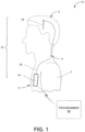
- FIG. 1 a conceptual drawing of an example neurostimulation system 10 that delivers deep brain stimulation (DBS) according to the present disclosure.
- neurostimulation system 10 may be directed to other applications such as spinal cord stimulation or pelvic floor stimulation.
- Neurostimulation system 10 includes at least a controller 14 (e.g., an implantable medical device (IMD) and/or a first module comprising one or more pulse generators) that may be surgically implanted in the chest region 3 of a patient 1, typically below the clavicle or in the abdominal region of patient 1.
- Controller 14 can be configured to supply the necessary stimulation pulses, e.g., in the form of current or voltage pulses (e.g., also referred to as a stimulation signal) to lead arrangement 18.
- DBS system 100 may further include a connecting cable 16 (e.g., an extension wire) connected to the controller 14 and running subcutaneously to the skull 2, such as along the neck 4, where it terminates at a connector for lead arrangement 18.
- a connecting cable 16 e.g.,
- DBS lead arrangement 18 may be implanted in the brain tissue, e.g., through a burr-hole in the skull.
- DBS lead arrangement 18 may include one or more leads coupled to at least one module including a switch matrix. In this manner, the switch matrix may be included in a second module 111 that is separate from controller 14.
- DBS system 100 may include one or more grounding electrodes. The grounding electrodes may be carried by connecting cable 16, for example, between controller 14 and lead arrangement 18.
- connecting cable 16 may be formed by two or more cables configured to connect to each other in parallel, and one or more of these cables may carry a grounding electrode.
- Lead arrangement 18 may include a plurality of electrodes arranged in a complex electrode array geometry.
- a complex electrode array geometry generally refers to an arrangement of stimulation electrodes at multiple non-planar or non-coaxial positions, in contrast to simple electrode array geometries in which the electrodes share a common plane or a common axis.
- An example of a simple electrode array geometry is an array of ring electrodes distributed at different axial positions along the length of a cylindrical lead.
- Another example of a simple electrode array geometry is a planar array of electrodes on a paddle lead.
- Electrodes in the complex electrode array geometry may include two or more electrodes (e.g., two, three, four, or more electrodes) at one axial position along the lead. This may be referred to as a "level" of the lead.
- the lead may also include two or more levels, whereas each level includes multiple electrodes at different angular positions.
- electrodes at one level may be staggered circumferentially with electrodes of an adjacent level. In other examples (e.g., electrodes of lead 60 in FIG. 4 ), electrodes at one level may be aligned circumferentially with electrodes of an adjacent level.
- the electrodes in the complex electrode array may be circular, rectangular, or non-rectangular areas of conductive material deposited at respective locations.
- the electrodes in the complex electrode array geometry may appear similar to non-contiguous, arc-like segments of a conventional ring electrode.
- a lead with a complex electrode array geometry may include multiple "rings" of such electrode segments. Each ring is disposed at a different axial position. Each electrode segment within a given ring is disposed at a different angular position.
- the lead may be cylindrical or have a circular cross-section of varying diameter.
- Another example of a complex electrode array geometry is an array of electrodes positioned on multiple planes or faces of a non-circular lead. As an illustration, arrays of electrodes may be positioned on opposite planes of a paddle lead or multiple faces of a lead having a polygonal cross-section.
- External programmer 20 wirelessly communicates with controller 14 as needed to provide or retrieve therapy information.
- Programmer 20 is an external computing device that the user, e.g., a clinician and/or patient 1, may use to communicate with controller 14.
- Programmer 20 may determine alternative electrode configurations and/or receive user selection of an alternative electrode configuration in order to reduce power consumption of the stimulation therapy, as described herein.
- programmer 20 may be a clinician programmer that the clinician uses to communicate with controller 14 and program one or more therapy programs for controller 14.
- programmer 20 may be a patient programmer that allows patient 1 to select programs and/or view and modify therapy parameters.
- the clinician programmer may include more programming features than the patient programmer. In other words, more complex or sensitive tasks may only be allowed by the clinician programmer to prevent an untrained patient from making undesirable changes to controller 14.
- programmer 20 When programmer 20 is configured for use by the clinician, programmer 20 may be used to transmit initial programming information to controller 14.
- This initial information may include hardware information, such as the type of leads and the electrode arrangement, the position of leads within the brain of patient 1, the configuration of an electrode array (e.g., electrodes 132 of FIG. 2A ), initial programs defining therapy parameter values such as selected electrode configurations, and any other information the clinician desires to program into controller 14.
- the clinician may also store therapy programs within controller 14 with the aid of programmer 20.
- the clinician may determine one or more therapy programs that may provide efficacious therapy to patient 1 to address symptoms associated with the patient condition. For example, the clinician may select one or more stimulation electrode combinations with which stimulation is delivered to the brain.
- programmer 20 may determine and present alternative electrode configurations that may consume less power during therapy and/or receive user input selecting one of the alternative electrode configurations.
- patient 1 may provide feedback to the clinician as to the efficacy of the specific program being evaluated or the clinician may evaluate the efficacy based on one or more physiological parameters of patient 1 (e.g., muscle activity or muscle tone).
- Programmer 20 may assist the clinician in the creation/identification of therapy programs by providing a methodical system for identifying potentially beneficial therapy parameter values.
- Programmer 20 may also be configured for use by patient 1. When configured as a patient programmer, programmer 20 may have limited functionality (compared to a clinician programmer) in order to prevent patient 1 from altering critical functions of controller 14 or applications that may be detrimental to patient 1. In this manner, programmer 20 may only allow patient 1 to adjust values for certain therapy parameters or set an available range of values for a particular therapy parameter.
- programmer 20 may rank the alternative electrode combinations based on the respective power consumption value such that the representation of at least some of the one or more alternative electrode combinations is indicative of the ranking. For example, programmer 20 may rank the alternative electrode combinations according to reduced energy consumption.
- the ranking may include the initial electrode combination as well.
- the power consumption values may be an absolute amount of energy used per unit time, a percentage of energy used when compared to the initial electrode combination, or a percentage of energy savings as compared to the initial electrode combination.
- the power consumption may be calculated using resistances or impedances determined using the R-matrix or Z-matrix approach, as discussed further below in relation to FIG. 12 .
- the power consumption values may be represented by the amount of time the battery of controller 14 will last before recharging when using the respective electrode combination.
- the examples generally described herein are related to selecting one or more alternative electrode combinations for stimulation therapy in order to reduce power consumption while retaining field similarity to achieve a desired therapeutic outcome.
- the processes described herein may be relevant to the selection of any stimulation parameters (e.g., current or voltage amplitude, pulse frequency, pulse width, duty cycle, monopolar or bipolar configurations, etc.) in order to determine other sets of stimulation parameters (e.g., one or more stimulation programs) that consume lower levels of power while also delivering stimulation fields providing therapeutic efficacy.
- the system or a user may provide one or more constraints in the selection of stimulation parameters, such as which electrodes to use, which electrodes to avoid, desired current or voltage amplitudes, desired pulse frequency, desired pulse width and/or duty cycle, and/or VNA or VTA that is desired or to be avoided.
- the system may automatically generate sets of stimulation parameters that satisfy these constraints and rank the sets of stimulation parameters by power consumption values and/or field similarity scores.
- the system may incorporate tissue resistances and various system resistances and/or impedances when calculating the power consumption values for each of these sets of stimulation parameters. In this manner, the system may generate sets of stimulation parameters without basing the parameters on an initial set of electrodes or initial electrode combination.
- Example constraints for selection of stimulation parameters may include a request for a certain number of lowest power consuming sets of stimulation parameters that include electrodes no more than a certain distance (or number of electrodes) from a desired circumferential position on the lead.
- the system may require a certain constraints in order to generate usable stimulation parameters, such as minimums or maximums for one or more of current, voltage, pulse width, frequency, number of electrodes, volume of activated tissue, etc. These constraints may be defaults set by the system and/or user definable.
- Other example constraints may be a request for the lowest power consuming rings of electrodes, or lower power consuming electrode combinations and stimulation parameters with electrodes falling within a defined area of the lead. Constrains for stimulation field profiles, depth of tissue activation from the lead, or any other therapeutic constraints may also be used or even required to perform the request.
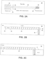
- FIGS. 2A, 2B, and 2C are schematic diagrams of an example thin film, lead, and probe of a neurostimulation system 10 for DBS.
- FIG. 2A illustrates an example, thin film 24
- FIG. 2B illustrates an example DBS lead 22
- FIG. 2C illustrates an example lead assembly 18 (e.g., a DBS probe) that include DBS lead 22 and a second module 17 (e.g., an active lead can (ALC) separate from controller 14).
- Second module 17 may include electronic means, such as a switch matrix, for addressing electrodes 28 disposed on the distal end 32 of the thin film 24. Electrodes 28 may be arranged at the distal end 42 of lead 22 and next to the distal tip 44 of the DBS lead 22.
- Electrodes 28 may be an example of a complex electrode array geometry with multiple levels of electrodes that are staggered in the circumferential direction. Although electrodes 28 include 18 electrodes, fewer or greater numbers of electrodes may be carried by lead 22. In one example, lead 22 may include 40 electrodes.
- Lead 22 may include a carrier 38 for thin film 24.
- Carrier 38 may be sized and shaped to providing the mechanical configuration of DBS lead 22 and the thin film 24.
- thin film 24 may be wrapped around the circumference or diameter of carrier 38.
- Thin film 24 may include at least one electrically conductive layer and may be constructed of a biocompatible material. The thin film 24 may be assembled to carrier 38 and further processed to constitute lead 22.
- the thin film 24 for a lead may be formed by a thin film product having a distal end 32, a cable 30 with metal tracks, and a proximal end 36.
- Proximal end 36 of the thin film 24 may be arranged at the proximal end 40 of lead 22 and is electrically connected to the second module 17.
- the second module 17 may include the switch matrix of the DBS steering electronics that selects different electrode combinations (e.g., selects which one or more electrodes are actively delivering an electrical signal) from electrodes 28.
- the distal end 32 comprises electrodes 28 for brain stimulation, for example.
- Proximal end 36 of thin film 24 includes interconnect contacts 34 for each metal track in the cable 30.
- the cable 30 comprises metal tracks or lines (not shown) to electrically connect each of distal electrodes 28 to a respective and designated proximal interconnect contact 34.
- Second module 17 may include a switch matrix, or multiplexer, that is used to couple, or decouple, each electrode of electrodes 28 to one or more pulse generator lines and ground provided to second module 17 via a connecting cable (e.g., connecting cable 16 of FIGS. 1 or 3 ). Second module 17 may also be electrically coupled to one or more ground electrodes.
- second module 17 may include other control electronics, such as a microprocessor or other integrated circuitry, resistors, and capacitors.
- second module 17 may include one or more signal generators (e.g., one or more pulse generators) that are provided in addition to, or instead of, one or more of the pulse generators provided by controller 14.
- the components of second module 17 may be incorporated into the housing of controller 14 such that a separate second module 17 is not necessary between controller 14 and electrodes 28.
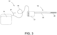
- FIG. 3 is a conceptual drawing of an example system 10 that delivers DBS.
- System 12 is described for brain applications, such as neurostimulation and/or neurorecording as a deep brain stimulation system 12 as shown in FIG. 1 .
- System 12 may include at least one lead assembly 18 (e.g., a probe) for brain applications with stimulation and/or recording electrodes 28.
- forty electrodes 28 can be provided on the outer body surface at the distal end of the lead assembly 18.
- Controller 14 e.g., a first module
- a second module 17 e.g., an active lead can
- a switch matrix of the second module 17 may direct the neurostimulation pulses P to the appropriate one or more electrodes (e.g., the electrode combination) for delivery to a patient.
- controller 14 can be or include an implantable pulse generator.
- controller 14 may be configured to simultaneously couple to two or more different second modules 17 and respective lead assemblies 18 via one or more connecting cables 16.
- system 12 may include controller 14 (e.g., a first module) that includes one or more pulse generators. Controller 14 may also include components such as a power supply, one or more processors, a memory, a communication unit for transmitting and/or receiving information from an external device, and other components.
- Second module 17 may include a switch matrix and, in some examples, one or more processors, a memory, and connectors for coupling lead 22 of FIG. 2 (where lead assembly 18 may include second module 17 and lead 22 carrying electrodes 28) and connecting cable 16.
- Second module 17 may have a housing encompassing the control electronics such as the switch matrix.
- the housing may be electrically nonconductive such as an epoxy or polymer that insulates and protects the components of second module 17. The electrically nonconductive material may reduce encapsulation of the housing and/or insulate the brain from any interference caused by the components of second module 17.
- Connecting cable 16 may connect controller 14 to second module 17.
- the plurality of electrodes 28 are disposed distal of second module 17 and on lead 22 of lead assembly 18.
- the control electronics for the plurality of electrodes 28 and the grounding electrode may provide at least one of neurostimulation and/or neurorecording via at least one electrode of the plurality of electrodes 28 and the grounding electrode.
- the control electronics are arranged in at least the first module 14 and the second module 17, but one or more additional modules may also include at least some of the control electronics.
- lead assembly 18 may include lead 22 constructed of a thin film 24 carrying the plurality of electrodes 28. Lead 22 may be electrically coupled to the switch matrix of second module 17.
- FIG. 4 is a conceptual drawing of another example lead 60 having a complex electrode array geometry.
- Lead 60 may be an alternative medical lead to lead 22 of FIGS. 2B and 3 .
- Lead 60 includes distal end 62 showing a plurality of electrodes 66A-C, 68A-C, 70A-C, and 72A-C.
- lead body 64 of lead 60 may be tubular in form and may have a substantially circular cross-section.
- lead body 64 of lead 60 may have any cross-sectional shape, such as rectangular, triangular, or other polygonal cross-sectional shapes in other examples, which may vary over the length of lead 60.
- An outer surface of lead body 64 may be formed from a biocompatible material such as, for example, polyurethane or silicone.
- Distal portion 62 of lead 60 also includes segmented electrodes 66A-C (collectively “electrodes 66"), segmented electrodes 68A-C (collectively “electrodes 68"), 70A-C (collectively “electrodes 70”), and 72A-C (collectively “electrodes 72").
- electrodes 66, 68, 70, and 72 are levels of electrodes disposed at respective axial positions on lead body 64.
- Electrodes 66C, 68C, 70C, and 72C are located on the circumferential portion of lead 60 that is on the opposite side from the visible side of lead 60 in FIG.4 .
- the approximate locations of electrodes 66C, 68C, 70C, and 72C are outlined with dotted lines.
- Electrodes 66, 68, 70, and 72 do not extend substantially around the entire periphery of the lead body 64. Each of electrodes 66, 68, 70, and 72 in the respective levels extend through arcs of 60 degrees, 80 degrees, 90 degrees, or as many as 119 degrees, although lesser or greater arcs may be used in other examples. Electrodes 66, 68, 70, and 72 in each respective level may be, but need not be, evenly spaced around the periphery of lead 60. Each of electrodes 66, 68, 70, and 72 can be made from an electrically conductive, biocompatible material, such as platinum iridium. In addition, one or more of 66, 68, 70, and 72 may function as sensing electrodes that monitor internal physiological signals of patient 1 ( FIG. 1 ).
- lead 60 includes four levels of segmented electrodes 66, 68, 70, and 72, respectively.
- Each level of electrodes includes an electrode circumferentially aligned with respective electrodes in other levels.
- electrodes 66A, 68A, 70A, and 72A are all circumferentially aligned with each other and at different axial positions on lead 60.
- electrodes of different levels may be staggered, or not circumferentially aligned.
- each level includes three electrodes, a level of segmented electrodes may include two, four, five, six, or even more electrodes disposed at the same axial position.
- Example lead 60 includes four levels of electrodes, but fewer levels such as one, two, or three or more levels such as five, six, or more can be used in other examples. Each level may have the same number of segmented electrodes, but in other examples, different levels may have different number of electrodes.
- lead 60 may include one or more ring electrodes in combination with one or more levels of multiple segmented electrodes. Ring electrodes may extend substantially around the entire periphery of lead 60. In some examples, multiple segmented electrodes may be used together as a ring electrode because they are configured to provide a stimulation field substantially similar to a full ring electrode. In some embodiments, the distances between each of the axial positions of each level (e.g., the positions of the levels of electrodes 66, 68, 70, and 72) may be approximately equal. However, the axial distance between electrodes may be varied between different levels of electrodes in other examples. Further, in some embodiments, although not illustrated in FIG. 4 , lead 60 may be coupled to controller 14 ( FIG. 1 ) or IMD 100 ( FIG. 5 ) directly or via one or more lead extensions.
- controller 14 FIG. 1
- IMD 100 FIG. 5
- FIG. 5 is a functional block diagram of an example IMD 100 configured to couple to one or more leads 60.
- IMD 100 may be similar to controller 14 of FIG. 1 and may include at least some functionality of second module 17 ( FIG. 3 ), however, second module 17 may not be located separate from IMD 100.
- Each of these modules include electrical circuitry configured to perform the functions described herein.
- IMD 100 includes processor 102, memory 114, stimulation generator 108, power monitor 109, measurement module 111, sensing module 106, switch module 110, telemetry module 104, sensor 112, and power source 122.
- Memory 114 may include any volatile or non-volatile media, such as a random access memory (RAM), read only memory (ROM), non-volatile RAM (NVRAM), electrically erasable programmable ROM (EEPROM), flash memory, and the like.
- RAM random access memory
- ROM read only memory
- NVRAM non-volatile RAM
- EEPROM electrically erasable programmable ROM
- Memory 114 may store computer-readable instructions that, when executed by processor 102, cause IMD 100 to perform various functions.
- Memory 114 may be a storage device or other non-transitory medium.
- memory 114 stores therapy programs 116 and configuration instructions 118 in common or separate memories or areas within memory 114.
- Each stored therapy program 116 defines a particular set of electrical stimulation parameters (e.g., a therapy parameter set), such as a stimulation electrode combination, electrode polarity, current or voltage amplitude, pulse width, and pulse rate.
- individual therapy programs may be stored as a therapy group, which defines a set of therapy programs with which stimulation may be generated.
- the stimulation signals defined by the therapy programs of the therapy group may be delivered together on an overlapping or non-overlapping (e.g., time-interleaved) basis.
- Configuration instructions 118 may include rules, algorithms, data, or any other information related to determining alternative electrode combinations, calculating power consumption values and stimulation field similarity scores, and selecting an alternative electrode combination for therapy.
- configuration instructions 118 may include one or more algorithms defining how to generate different alternative electrode combinations based on an initial electrode combination.
- Configuration instructions 118 may also include instructions regarding whether processor 102 should automatically select an alternative electrode combination or present alternative electrode combinations to a user for selection.
- configuration instructions 118 may only include some information necessary to determine and select alternative electrode combinations because programmer 20 or another device may perform some or all of the steps in the process.
- the R-matrix and/or Z-matrix may be used to calculate the power consumption that occurs within the tissue of the patient and/or the tissue of the patient and all other electrical components between the stimulation generator and the tissue, such that the total power consumption for a system delivering stimulation therapy would include the power consumption by the tissue and the power consumption that occurs within the system (e.g., within the stimulation generator, between the tissue and the stimulation generator, and other electrical components).
- Processor 102 may control measurement module 111 to measure the R-matrix and/or Z-matrix, or any other representation of tissue resistance and/or load impedance, once or several times over the course of stimulation therapy. For example, processor 102 may initially control measurement module 111 to measure the R-matrix after implantation of lead 60 and prior to selecting stimulation parameters for stimulation therapy. Since the composition of tissue around lead 60 and the electrodes thereof may change over time (e.g., due to encapsulation, scar tissue, etc.), processor 102 may periodically re-measure the R-matrix according to a predetermined schedule and/or in response to detected events.
- Detected events may include a visit by the patient to a clinic, a replaced implantable component, the loss or failure of an electrode (or corresponding switch or conductor), or even a traumatic accident endured by the patient that may have moved the lead relative to tissue.
- the updated R-matrix may provide for more accurate power consumption values and more accurate stimulation field determination with associated similarities of alternative electrode combinations or other sets of stimulation parameters.
- the R-matrix or Z-matrix may describe the resistance, or impedance, of tissue for a specific patient within which the electrodes are implanted. It may also describe the load impedance (e.g., electrical components between tissue and stimulation generator plus the tissue itself) connected to the each current source of the stimulation generator. In this manner, the R-matrix or Z-matrix may provide specific information regarding the tissue-electrode interface and current path through tissue between electrodes and these electrodes and the stimulation generator.
- the R-matrix or Z-matrix may be calculated applying a test stimulation current between two electrodes or between an electrode and a housing of IMD 100, for example, measuring the resulting excitation voltage, and deriving an impedance between the electrodes based on the test stimulation current and the resulting excitation voltage. This process may be repeated for all different electrodes, in some examples, or in only some electrode and extrapolated to other electrodes, in other examples.
- the test stimulation currents may be at sub-threshold levels (e.g., 0.1 mA) in some examples to avoid neuron activation during impedance measurement, and the resulting measured resistances may be extrapolated up to typical therapeutic currents (e.g., 3.0 mA) to provide an R-matrix or Z-matrix representative of actual therapy delivery.
- the R-matrix may be determined using test stimulation currents at normal therapeutic current levels or using actual therapeutic stimulation during therapy. Example methods for determining the R-matrix or Z-matrix for tissue of the patient are described in Patent Cooperation Treaty Publication No. WO 2011/107917 A1 by Emil Toader et al. , and entitled "Method and System for Determining Settings for Deep Brain Stimulation".
- Processor 102 may include any one or more of a microprocessor, a controller, a digital signal processor (DSP), an application specific integrated circuit (ASIC), a field-programmable gate array (FPGA), discrete logic circuitry, and the functions attributed to processor 102 herein may be embodied as firmware, hardware, software or any combination thereof.
- Processor 102 controls stimulation generator 108 according to therapy programs 116 stored in memory 114 to apply particular stimulation parameter values specified by one or more of programs, such as amplitude, pulse width, and pulse rate.
- the set of electrodes 66, 68, 70, and 72 of lead 60 are coupled to switch module 110 for delivery of electrical stimulation.
- two or more leads may be coupled to switch module 110 with similar or varying configurations of electrodes.
- Processor 102 also controls switch module 110 to apply the stimulation signals generated by stimulation generator 108 to selected combinations of electrodes 66, 68, 70, and 72.
- switch module 110 may couple stimulation signals to selected conductors within lead 60, which, in turn, deliver the stimulation signals across selected electrodes 66, 68, 70, and 72.
- Switch module 110 may be a switch array, switch matrix, multiplexer, or any other type of switching module configured to selectively couple stimulation energy to selected electrodes 66, 68, 70, and 72 and to selectively sense bioelectrical brain signals with selected electrodes 66, 68, 70, and 72.
- stimulation generator 108 is coupled to electrodes 66, 68, 70, and 72 via switch module 110 and conductors within lead 60.
- IMD 100 does not include switch module 110.
- Stimulation generator 108 may be a single channel or multi-channel stimulation generator.
- stimulation generator 108 may be capable of delivering a single stimulation pulse, multiple stimulation pulses, or a continuous signal at a given time via a single electrode combination or multiple stimulation pulses at a given time via multiple electrode combinations.
- stimulation generator 108 and switch module 110 may be configured to deliver multiple channels on a time-interleaved basis.
- switch module 110 may serve to time divide the output of stimulation generator 108 across different electrode combinations at different times to deliver multiple programs or channels of stimulation energy to patient 1.
- sensing module 106 is incorporated into a common housing with stimulation generator 108 and processor 102 in FIG. 5 , in other examples, sensing module 106 may be in a separate housing from IMD 100 and may communicate with processor 102 via wired or wireless communication techniques.
- Example bioelectrical brain signals include, but are not limited to, a signal generated from local field potentials within one or more regions of the brain. EEG and ECoG signals are examples of local field potentials that may be measured within the brain. However, local field potentials may include a broader genus of electrical signals within the brain of patient 1.
- Sensor 112 may include one or more sensing elements that sense values of a respective patient parameter.
- sensor 112 may include one or more accelerometers, optical sensors, chemical sensors, temperature sensors, pressure sensors, or any other types of sensors. Sensor 112 may output patient parameter values that may be used as feedback to control delivery of therapy.
- IMD 100 may include additional sensors within the housing of IMD 100 and/or coupled via lead 60 or other leads.
- IMD 100 may receive sensor signals wirelessly from remote sensors via telemetry module 104, for example.
- one or more of these remote sensors may be external to patient (e.g., carried on the external surface of the skin, attached to clothing, or otherwise positioned external to the patient). Each of the sensor signals may be calibrated by identified patient behavior from video information and incorporated in the feedback control of therapy.
- Telemetry module 104 supports wireless communication between IMD 100 and an external programmer 20 or another computing device under the control of processor 102.
- Processor 102 of IMD 100 may receive, as updates to programs, values for various stimulation parameters such as amplitude and/or alternative electrode combination(s), from programmer 20 via telemetry module 104.
- the updates to the therapy programs may be stored within therapy programs 116 portion of memory 114.
- Telemetry module 104 in IMD 100, as well as telemetry modules in other devices and systems described herein, such as programmer 20, may accomplish communication by radiofrequency (RF) communication techniques.
- telemetry module 104 may communicate with external medical device programmer 20 via proximal inductive interaction of IMD 100 with programmer 24. Accordingly, telemetry module 104 may send information to external programmer 24 on a continuous basis, at periodic intervals, or upon request from IMD 100 or programmer 24.
- RF radiofrequency
- Power source 122 delivers operating power to various components of IMD 100.
- Power source 122 may include a small rechargeable battery, a non-rechargeable battery, and/or another type of energy storage device such as one or more super capacitors, and a power generation circuit to produce the operating power. Recharging may be accomplished through proximal inductive interaction between an external charger and an inductive charging coil within IMD 100.
- power requirements may be small enough to allow IMD 100 to utilize patient motion and implement a kinetic energy-scavenging device to trickle charge a rechargeable battery.
- traditional batteries may be used for a limited period of time.
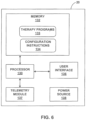
- FIG. 6 is a functional block diagram of an example external programmer 20 for an IMD such as IMD 100 or controller 14.
- programmer 20 may generally be described as a hand-held device, programmer 20 may be a larger portable device or a more stationary device.
- programmer 20 may be included as part of an external charging device or include the functionality of an external charging device.
- programmer 20 may include a processor 130, memory 132, user interface 136, telemetry module 137, and power source 138.
- Memory 132 may store instructions that, when executed by processor 130, cause processor 130 and external programmer 20 to provide the functionality ascribed to external programmer 20 throughout this disclosure.
- configuration instructions 134 in memory 132 may cause programmer 20 to determine alternative electrode combinations and receive user input selecting an alternative electrode combination to reduce power consumption of stimulation therapy.
- programmer 20 comprises any suitable arrangement of hardware, alone or in combination with software and/or firmware, to perform the techniques attributed to programmer 20, and processor 130, user interface 136, and telemetry module 137 of programmer 20.
- programmer 20 may include one or more processors, such as one or more microprocessors, DSPs, ASICs, FPGAs, or any other equivalent integrated or discrete logic circuitry, as well as any combinations of such components.
- Programmer 20 also, in various examples, may include a memory 132, such as RAM, ROM, PROM, EPROM, EEPROM, flash memory, a hard disk, a CD-ROM, comprising executable instructions for causing the one or more processors to perform the actions attributed to them.
- processor 130 and telemetry module 137 are described as separate modules, in some examples, processor 130 and telemetry module 137 are functionally integrated. In some examples, processor 130 and telemetry module 137 correspond to individual hardware units, such as ASICs, DSPs, FPGAs, or other hardware units.
- Memory 132 may store instructions that, when executed by processor 130, cause processor 130 and programmer 20 to provide the functionality ascribed to programmer 20 throughout this disclosure.
- memory 132 may include instructions that cause processor 130 to obtain a parameter set from memory, select a spatial electrode movement pattern, or receive a user input and send a corresponding command to IMD 14, or instructions for any other functionality.
- memory 132 may include a plurality of therapy programs 133 (similar to therapy programs 116 of FIG. 5 ), where each therapy program includes a parameter set that defines stimulation therapy.
- Configuration instructions 134 may be similar to configuration instructions 118 of IMD 100 and may include rules, algorithms, data, or any other information related to determining alternative electrode combinations, calculating power consumption values and stimulation field similarity scores, and selecting an alternative electrode combination for therapy.
- configuration instructions 134 may include one or more algorithms defining how to generate different alternative electrode combinations based on an initial electrode combination.
- Configuration instructions 134 may also include instructions regarding whether processor 130 should automatically select an alternative electrode combination or present alternative electrode combinations to a user for selection.
- configuration instructions 134 may define how power consumption values, field similarity scores, and/or visual representations of stimulation fields are determined or calculated and/or generated for presentation to a user.
- configuration instructions 134 may only include some information necessary to determine and select alternative electrode combinations because programmer 20 or another device may perform some or all of the steps in the process.
- User interface 136 may include a button or keypad, lights, a speaker for voice commands, a display, such as a liquid crystal (LCD), light-emitting diode (LED), or organic light-emitting diode (OLED).
- a display such as a liquid crystal (LCD), light-emitting diode (LED), or organic light-emitting diode (OLED).
- the display may be a touch screen.
- User interface 136 may be configured to display any information related to the delivery of stimulation therapy, alternative electrode combinations, or any other such information.
- User interface 136 may also receive user input via user interface 136. The input may be, for example, in the form of pressing a button on a keypad or selecting an icon from a touch screen.
- Telemetry module 137 may support wireless communication between controller 114 or IMD 14 and programmer 20 under the control of processor 130. Telemetry module 137 may also be configured to communicate with another computing device via wireless communication techniques, or direct communication through a wired connection. In some examples, telemetry module 137 may be substantially similar to telemetry module 104 of IMD 100 described herein, providing wireless communication via an RF or proximal inductive medium. In some examples, telemetry module 137 may include an antenna, which may take on a variety of forms, such as an internal or external antenna.
- Examples of local wireless communication techniques that may be employed to facilitate communication between programmer 20 and controller 14 or IMD 100 include RF communication according to the 802.11 or Bluetooth specification sets or other standard or proprietary telemetry protocols. In this manner, other external devices may be capable of communicating with programmer 20 without needing to establish a secure wireless connection.
- telemetry module 137 may be configured to transmit a spatial electrode movement pattern or other stimulation parameter values to controller 14 or IMD 100 for delivery of stimulation therapy.
- FIG. 7 is a conceptual diagram of an example distributed system 140 that operates over a network.
- system 140 that includes networked server 146 coupled to IMD 14 (and/or controller 14) and one or more computing devices 150 via network 142.
- Server 146 e.g., a networked external computing device
- computing devices 150A-150N that are coupled to the IMD 14 and programmer 20 via a network 142.
- Network 142 may be generally used to transmit sensed data and/or information related to determining and/or selecting alternative electrode combinations.
- the information transmitted by IMD 14 may allow a clinician or other healthcare professional to monitor patient 1 remotely.
- IMD 14 may use a telemetry module to communicate with programmer 20 via a first wireless connection, and to communicate with access point 144 via a second wireless connection, e.g., at different times.
- access point 144, programmer 20, server 146 and computing devices 150A-150N are interconnected, and able to communicate with each other through network 142.
- one or more of access point 144, programmer 20, server 146 and computing devices 150A-150N may be coupled to network 142 via one or more wireless connections.
- server 146 may be configured to provide a secure storage site for archival of video information, therapy parameters, patient parameters, or other data that has been collected and generated from IMD 14 and/or programmer 20.
- Network 142 may comprise a local area network, wide area network, or global network, such as the Internet.
- the system of FIG. 7 may be implemented, in some aspects, with general network technology and functionality similar to that provide by the Medtronic CareLink ® Network developed by Medtronic, Inc., of Minneapolis, MN.
- FIG. 8 is a conceptual diagram of example alternative electrode combinations selected based on the distance of other electrodes to an electrode of the initial electrode combination.
- electrodes 160 is a set of 18 electrodes in a staggered configuration such as electrodes 28 of FIG. 2A .
- Alternative electrode combinations may be based on an initial electrode combination and the distance from an electrode of an initial electrode combination to adjacent electrodes.
- programmer 20 may start with an initial electrode combination and add electrodes to generate alternative electrode combinations.
- the distances may be the Euclidian distance based on an "unwrapping" or "unrolling" of the complex electrode array geometry as shown in FIG. 8 .
- Electrode A may be the single electrode of the initial electrode combination. Adjacent to electrode A are four electrodes B that are each the same distance 162 from electrode A.
- Programmer 20 may thus define a first alternative electrode combination as electrodes A and B (e.g., 5 electrodes).
- programmer 20 may add electrodes C to determine the second alternative electrode combination as electrodes A, B, and C (e.g., 9 electrodes).
- programmer 20 may add electrodes D to determine the third alternative electrode combination as electrodes A, B, C, and D (e.g., 13 electrodes). By iteratively adding electrodes at further distances from electrode A, programmer 20 may have determined some electrode combinations with lower impedances and/or power consumption values than just electrode A.
- the distances 162, 164, and 166 are calculated from the center of electrode A to the center of the other respective electrodes.
- the distance between electrodes may be calculated from the middle of the initial electrode to the nearest edge of another electrode, from the nearest edges between two electrodes, or according to any other algorithm.
- Distances 162, 164, and 166 are calculated as Euclidian distances. Other methods for determining distances may be used in other examples.
- programmer 20 may calculate the arc distance around the surface of the lead from one electrode to another electrode.
- programmer 20 may model the expected average path of electrical current through tissue from the initial electrode to alternative electrodes. In other words, the electrical path may arc at some distance away from the surface of the lead. Programmer 20 may use the expected average path of the electrical current as the distance between two electrodes.
- all electrodes at each equidistant location from electrode A may be used in order to maintain the symmetry of the stimulation field to the stimulation field of the initial electrode combination.
- Programmer 20 may continue to determine additional alternative electrode combinations if further electrodes of the complex electrode array geometry are available or until a symmetrical group of electrodes can no longer be added. However, additional electrodes will continue to alter the stimulation field.
- electrodes added for a single alternative electrode combination may not all be at exactly equidistant from the initial electrode. Instead, programmer 20 may use two or more electrodes within a range of distances of the initial electrode. Using a distance range may be appropriate for electrode arrays that are unsymmetrical or have varied distances between adjacent electrodes. Such a range may also be useful when the initial electrode combination includes two or more electrodes.
- Electrodes 160 are shown as staggered levels of electrodes. However, different electrode arrays may have different configurations of electrodes. For example, electrodes 160 may be shown in aligned rows and columns that represent lead 60 of FIG. 4 . Any type of electrode configuration may be shown in such a manner.
- programmer 20 may continue to generate alternative electrode combinations until the field similarity score drops below a predetermined threshold. For example, programmer 20 may calculate a field similarity score for a newly determined alternative electrode combination with respect to the initial electrode combination. If the field similarity score is below a threshold of 80%, for example, programmer 20 may stop generating any additional alternative electrode combinations because further additions of electrodes will likely further decrease the field similarity score. Programmer 20 may or may not discard any alternative electrode combinations that have a field similarity score below the predetermined threshold.
- the predetermined threshold may be set to any desired threshold, such as about 50%, 60%, 70%, 80%, or 90%, or any other threshold lower, higher, or in between these thresholds.
- the predetermined threshold for the field similarity score may be used as one input for determining how many alternative electrode combination are generated.
- Programmer 20 may, for example, generate at least a predetermined number of alternative electrode combinations even if one or more of the alternative electrode combinations have a field similarity score below the predetermined threshold.
- programmer 20 may only generate the predetermined number of alternative electrode combinations (e.g., two, three, four, five, or more) even if the field similarity scores are still above the predetermined threshold.
- programmer 20 may assume the same stimulation parameters (e.g., current or voltage amplitude, pulse width, pulse frequency, etc.) for each of the electrodes across all electrode combinations.
- programmer 20 may use one or more different stimulation parameters between different alternative electrode combinations or even one or more different stimulation parameters for different electrodes within the same alternative electrode combination.
- more centrally located electrodes of an alternative electrode combination may use higher current or voltage amplitudes than more peripheral electrodes.
- peripheral electrodes of the alternative electrode combinations may have higher current or voltage amplitudes than more centrally located electrodes of the electrode combination.
- programmer 20 may assume that all electrodes 160 of the complex electrode array are available for stimulation and inclusion in alternative electrode combinations. However, one or more electrodes may not function as intended due to conductor fracture between an electrode and the stimulation generator, switch matrix error or failure, or even excessive encapsulation that raises the impedance of an electrode. Controller 14 or IMD 100 may periodically test each electrode and determine whether or not each electrode is still functional or available to deliver stimulation therapy. This periodic testing may include re-determining, re-measuring or re-calculating the electrode resistance (e.g., R-matrix) or impedance (e.g., Z-matrix) for all electrodes, electronics, and tissue associated with the system.
- R-matrix the electrode resistance
- impedance e.g., Z-matrix
- Programmer 20 may use the results of the test (or resistance/impedance matrix) when determining alternative electrode combinations. Good electrodes may be available, or alternatively, bad electrodes may be restricted from being used in an electrode combination. Therefore, when determining alternative electrode combinations, programmer 20 may only use functioning electrodes for each alternative electrode combination.
- the example of FIG. 8 may be used when the initial electrode combination and alternative electrode combinations are used in a monopolar or unipolar configuration.
- one or more ground electrodes may be located on controller 14 of IMD 100 (e.g., carried on the implant housing), on a portion of the lead or connection between the IMD and the lead, or as part of second module 17.
- one or more electrodes e.g., one or more levels of a complex electrode array geometry
- that are not selected as active electrodes may be utilized as a ground electrode that sinks current that is sourced from the active electrodes.
- bipolar configurations of electrodes may be used.
- alternative electrode combinations may be determined for one or more of the initial anode and/or cathode electrodes of the initial electrode combination.
- programmer 20 may calculate various metrics to characterize the alternative electrode combinations.
- Programmer 20 may calculate a power consumption value and a field similarity score for each of the alternative electrode combinations.
- Table 1 provided below provides information for each of the initial (or original) electrode combination and the determined alternative electrode combinations.
- Table 1 includes the Euclidian distance, Power consumption, Power consumption reduction percentage, and Sorensen-Dice field similarity score for each electrode combination. Both of the power consumption and power consumption reduction percentage may be referred to as a power consumption reduction value.
- Table 1 provides information for each of the initial (or original) electrode combination and the determined alternative electrode combinations.
- Table 1 includes the Euclidian distance, Power consumption, Power consumption reduction percentage, and Sorensen-Dice field similarity score for each electrode combination. Both of the power consumption and power consumption reduction percentage may be referred to as a power consumption reduction value. Table 1.
- the "Original" electrode combination corresponds to electrode A
- “Configuration 1” corresponds to electrodes A and B
- “Configuration 2” corresponds to electrodes A, B, and C
- “Configuration 3” corresponds to electrodes A, B, C, and D.
- the Euclidian distance represents the distances 162, 164, and 166, respectively.
- the Power consumption may be the absolute power consumption based on the common current (e.g., 1.5 mA) and the total impedance of the electrodes in each electrode combination, and the impedance of the remainder of the system (which may include additional electronics and/or tissue impedances associated with each electrode).
- the Power consumption reduction percentage may be the percentage decrease of the total power consumption for the alternative electrode combination as compared to the initial electrode combination.
- the Sorensen-Dice field similarity score may be the numerical value attributed to the similarity of the stimulation field from the alternative electrode combination to the stimulation field from the initial electrode combination.
- the information in Table 1 may be output and presented to a user as a representation of the alternative electrode combination.
- a user may review the information of Table 1 and base the selection of one of the alternative electrode combination on the data of Table 1. If programmer 20, controller 14, IMD 100, or any other device automatically selects an alternative electrode combination for stimulation therapy, programmer 20 may still present the information for the selected alternative electrode combination or even all of the possible alternative electrode combinations for the user to review. Programmer 20 may require the user to confirm the automated selection of the alternative electrode combination, or programmer 20 may present a mechanism for the user to reject the selected alternative electrode combination and receive user selection for a different alternative electrode combination or even the initial electrode combination if none of the alternative electrode combinations are acceptable to the user.
- the alternative electrode combinations may be ranked in Table 1 according to a variety of factors. In one example, the alternative electrode combination may be ranked according to decreasing field similarity scores. In other examples, the alternative electrode combinations may be ranked based in decreasing power consumption values, increasing number of electrodes, or any other variations. In some examples, alternative electrode combinations may be displayed with information regarding patient feedback for the various alternative electrode combinations if the combination has been used and reviewed by the patient. In this manner, programmer 20 may display feedback scores from the patient that may or may not correspond to the calculated field similarity score.
- FIG. 9 is a conceptual diagram of example stimulation fields deliverable from alternative electrode combinations.
- programmer 20 (or any other device described herein) has generated and presented graphical representations of the stimulation fields deliverable by each of the initial electrode combination and the alternative electrode combinations discussed in FIG. 8 .
- Representation 170 may be a representation of the stimulation fields that can be output and displayed to a user via programmer 20, for example.
- Axial views 172 include the axial views of each of stimulation fields 180A, 180B, 180C, and 180D (collectively "stimulation fields 180") with respect to lead 176.
- stimulation fields 180 include the axial views of each of stimulation fields 180A, 180B, 180C, and 180D (collectively "stimulation fields 180" with respect to lead 176.
- stimulation field 180A corresponds to the initial electrode configuration of electrode A
- stimulation field 180B corresponds to the alternative electrode configuration of electrodes A and B
- stimulation field 180C corresponds to the alternative electrode configuration of electrodes A, B, and C
- stimulation field 180D corresponds to the alternative electrode configuration of electrodes A, B, C, and D.
- Field width scale 178 includes multiple dotted lines that indicate the distance the stimulation field reaches out from lead 176.
- Field width scale 178 is provided with each of stimulation fields 180 in order to review the relative sizes of each stimulation field.
- field width scale 178 shows that stimulation field 180A provides a wider stimulation field than stimulation field 180D.
- Each dotted line of field width scale 178 may correspond to a respective distance from lead 176 in a scale of millimeters, centimeters, inches, or any other distance scale.
- Side views 174 include side views of each of stimulation fields 180A, 180B, 180C, and 180D with respect to the side view of lead 176. As shown in side views 174, as more electrodes are used to generate the stimulation fields 180A-180D, the length of the stimulation field increases in size. In other words, stimulation field 180A from one electrode provides a shorter stimulation field along the length of lead 174 than stimulation field 180D provided by 13 electrodes. Although not shown in FIG. 9 , a field height scale (such as field width scale 178) may also be shown in conjunction with the side views of stimulation fields in side views 174.
- FIG. 10 is a flow diagram of an example process for determining alternative electrode combinations according to the present disclosure.
- the process of FIG. 10 will be described with regard to processor 130 of programmer 20. However, this process, or portions of the process, may be performed by other devices such as controller 14, IMD 100, networked server 146, or computing devices 150. In this manner, one device, or several networked devices, may perform the process of FIG. 10 .
- processor 130 identifies a first electrode combination (e.g., set of one or more electrodes or an initial electrode combination) (200).
- processor 130 may identify the first electrode combination by receiving user input that defines the first electrode combination or from another therapy programmer. In other examples processor 130 may identify the first electrode combination from a selected stimulation program, one or more electrodes determined as available for stimulation from a user, or as corresponding to a user or system desired anatomical region or direction with respect to the lead. If processor 130 determines that there is an alternative electrode combination available ("YES" branch of block 202), processor 130 may determine the new alternative electrode combination (204). Processor 130 may determine the new alternative electrode combination by adding additional electrodes to the electrodes of the initial electrode combination or the previously generated alterative electrode combination.
- processor 130 may then determine (e.g., calculate or measure) power consumption values for each of the alterative electrode combinations (206). Processor 130 also calculates stimulation fields for each of the alterative electrode combinations (208). Using the calculated stimulation fields, processor 130 also determines the similarity of the stimulation field of each alternative electrode combination to the stimulation field of the first electrode combination (210). For example, processor 130 may calculate a field similarity score such as a Sorensen-Dice coefficient.
- processor 130 may output, for display, a representation of the power consumption values and stimulation field similarity values for one or more of the alterative electrode combinations (212). For example, processor 130 may control user interface 136 to display the information of Table 1 and/or the stimulation fields of representation 170 of FIG. 9 . Via user interface 136, processor 130 receives user selection of one of the alterative electrode combination for stimulation therapy (214). Processor 130 then controls an IMD (e.g., controller 14 or IMD 100) to deliver stimulation therapy according to the selected alternative electrode combination (216). In other examples, as described herein, processor 130 may automatically select one of the alterative electrode combinations. Processor 130 may request user confirmation of the selected alterative electrode combination and/or present information about the selected alterative electrode combination.
- IMD e.g., controller 14 or IMD 100
- Processor 130 may initiate the process of FIG. 10 in a variety of situations.
- Processor 130 may propose alterative electrode combinations any time that processor 130 receives a user defined electrode combination intended for stimulation therapy.
- processor 130 may propose alterative electrode combinations when a therapy program is first selected to be used for stimulation therapy.
- processor 130 may propose alterative electrode combination in response to detecting inadequate battery life or some other unexpected or undesirable power usage of the IMD.
- Processor 130 may thus propose alterative electrode combinations in order to extend battery life of the system or otherwise improve the amount of time for which the IMD can deliver stimulation therapy between recharging intervals.
- the process of FIG. 10 is directed to determining alternative electrode combinations using the same or similar stimulation parameters such as pulse width, current or voltage amplitude, pulse frequency, etc.
- processor 130 may perform an alternative process for FIG. 10 in which different sets of stimulation parameters, not just different electrode combinations, are determined. These different sets of stimulation parameters may include alternatives to one or more of the pulse frequency, pulse width, duty cycle, current or voltage amplitude, or any other stimulation parameter. For each of these alternative sets of stimulation parameters determined by processor 130, processor 130 may determine respective power consumption values and stimulation field similarity values. Processor 130 may then use an alternative set of stimulation parameters to control delivery of stimulation therapy to the patient.
- a process of selecting different sets of stimulation parameters may require one or more constraints that limit the system to certain ranges of values such as minimum or maximums for number of electrodes, current or voltage amplitude, pulse width, pulse frequency, etc.
- FIG. 11 is a conceptual diagram illustrating an example monopolar stimulation circuit that represents elements of the system that may contribute to the impedance of one or more electrodes for each of a respective current source.
- Circuit 220 may be representative of a stimulation circuit associated with system 10, for example.
- Circuit 220 may represent various sources of current, capacitance, and resistance that contributes to the overall impedance of the system for any given electrode or electrode combination. As shown in FIG.
- circuit 220 includes stimulator block 222 representing elements of controller 14 or IMD 100 (which may include two push-pull current sources 230A and 230B as shown, one push-pull current source, or three or more push-pull current sources), lead cable block 224 representing elements of connecting cable 16, second module block 226 representing elements of second module 17, lead block 228 representing elements of lead 22 and electrodes thereof, and tissue block 230 representing the resistance of tissue between the electrodes and ground terminal 246.
- These components of circuit 220 may represent or model one or more electrical components that may contribute to the overall system impedance and power dissipation of the circuit.
- circuit 220 may represent actual electrical components present in the system in some examples, circuit 220 may be a general approximation of the electrical characteristics of one or more electrical components of a stimulation circuit for modeling purposes.
- Sub-circuit 221A may include those components used to provide stimulation from current source 230A and sub-circuit 221B includes those components used to provide stimulation from push-pull current source 230B.
- contributors to the overall impedance (or also referred to as a collective impedance for an electrode combination) or overall load of push-pull current source 230A may include blocking capacitor 232A of stimulator block 222 and resistance 234A of one or more conductors of lead block 228.
- Additional contributors to the load impedance of push-pull current source 230A of sub-circuit 221A may include components of second module block 226 such as one or more blocking capacitors 236A, resistors 238A and 238B of a switch matrix, blocking capacitors 240A and 240B, components of lead block 228 such as lead resistors 242A and 242B (e.g., conductive traces or conductors) and corresponding capacitors 244A and 244B representing the respective electrodes (e.g., the interface between electrodes and adjacent tissue), and impedance of tissue block 230 before the electrical current reaches ground terminal 246 (e.g., the housing of controller 14 or a return electrode).
- second module block 226 such as one or more blocking capacitors 236A, resistors 238A and 238B of a switch matrix, blocking capacitors 240A and 240B, components of lead block 228 such as lead resistors 242A and 242B (e.g., conductive traces or conduct
- tissue block 230 may represent the R-matrix, or resistance matrix, or Z-matrix, or impedance matrix, of the electrodes of the lead.
- the R-matrix and Z-matrix may be described as the brain tissue spreading resistance or impedance, respectively, in some examples and be used as a representation of the tissue resistance or impedance that corresponds to each electrode.
- the R-matrix or Z-matrix may be measured via test pulses or other excitation waveforms (e.g., square wave currents, voltages, etc.) generated from the stimulation generator (e.g., one or more current sources) or separate measurement module (e.g., a measurement module 111 of FIG.
- Sub-circuit 221A is representative of two electrodes being driven, but any number of electrodes may be represented by respective components such as resistance 238A, capacitor 240A, resistor 242A, and capacitor 244A.
- Impedances for sub-circuit 221B may be similar to the components of sub-circuit 221A.
- sub-circuit 221B may include push-pull current source 230B, blocking capacitor 232B, resistor 234B, blocking capacitor 236B, resistors 238C and 238D, capacitors 240C and 240D, resistors 242C and 242D, and capacitors 244C and 244D.
- Each of the components of sub-circuits 221A and 221B represent one or more of those components, so the illustration of only one component is to simplify the discussion of possible elements that contribute to the system and/or load impedance. In other examples, additional or fewer sources of capacitance and/or resistance may be present in the system.
- blocking capacitors 236A and 240A and resistor 238A, 238B, 242A and 242B may not be present in IMD 100 that includes the simulation generator 108 (e.g., one or more current sources) and switch module 110.
- Circuit 220 represents a monopolar stimulation configuration. However, similar circuits can be used to model or represent components that contribute to impedances for bipolar stimulation configurations. Other models can be used to represent components that contribute to impedances for multi-implant set-ups.
- Power consumption values calculated or measured for each respective sub-circuit 221A and 221B may incorporate the effects of current injected to tissue block 230 by the other sub-circuit in multiple current source examples.
- current e.g., I PG1
- push-pull current source 230A applied to tissue block 230 which has a resistance, which can be represented by the R-matrix or Z-matrix, creates a voltage potential on the electrodes and components of sub-circuit 221B because the same tissue is in electrical contact with all electrodes of both sub-circuits 221A and 221B.
- FIG. 12 is a conceptual diagram illustrating an example load model for multiple stimulation generators in a system.
- Load model 250 may represent circuits similar to sub-circuits 221A and 221B of FIG. 11 and illustrate the coupling that can occur between electrodes of the different sub-circuits each having its own current source.
- Load model 250 includes stimulator blocks 222A and 222B which include the respective current sources and blocking capacitors for sub-circuits 221A and 221B of FIG. 11 .
- Each stimulator block 222A and 222B can inject a current, I 1 and I 2 , respectively, into the stimulation load 253 represented by the large dotted-line box.
- Capacitors 251A and 251B represent capacitances in the respective circuit due to blocking capacitors, for example, and resistors 252A and 252B represent resistances in the respective circuit due to switches, conductors, etc.
- Capacitors 254A and 254B represent the capacitances of the electrode-tissue interface of the electrode combinations for each circuit.
- Tissue 266 may be a more detailed model of tissue block 230 in FIG. 11 .
- the elements within tissue 266 represent the elements of the R-matrix or Z-matrix as discussed herein.
- resistor 256A represents the resistance of tissue associated with the electrode combination driven by current from stimulation block 222A
- resistor 256B represents the resistance of tissue associated with the electrode combination driven by current from stimulation block 222B.
- Resistor 260 may represent the bulk resistance of the tissue far from the electrodes (which may be relatively small)
- capacitor 262 may represent the capacitance of the controller housing when used as the grounded (264) return electrode in this example monopolar stimulation load model. If each of stimulation block 222A and 222B, and their respective circuit elements, operated independently or into electrically isolated tissue, the load for each respective current source would not affect the load to the other current source.
- Controlled voltage source 258A represents the change in voltage stimulation block 222A experiences due to the current injected by stimulation block 222B
- controlled voltage source 258B represent the change in voltage stimulation block 222B experiences due to the current injected by stimulation block 222A.
- each controlled source 256A and 256B may be calculated by the product of the transresistance (R x ) for the electrode combinations connected to stimulation block 222A and 222B and the current (I 1 or I 2 ) injected into the tissue by the other circuit.
- V 1,e and V 2,e represents the voltages developed across the spreading resistance for each electrode combination for each circuit (which may be the main contributor to tissue resistance). In this manner, the known or measured R-matrix or Z-matrix can be used to establish this relationship and determine the arising voltages and currents for the tissue 266.
- V 1 , e V 2 , e R 11 R x R x R 22 I 1 I 2 , where V 1,e and V 2,e are the voltages developed across the spreading resistance of each electrode combination of each sub-circuit, R11 is the resistance of resistor 256A, R22 is the resistance of resistor 256B, and R x is the transresistance of the tissue.
- a larger matrix may be used to represent each electrode, or electrode combination, in some examples, while a larger matrix may be used to represent more than two stimulation blocks.
- a full matrix is derived for all electrodes of a lead (e.g., a 40 x 40 matrix for 40 electrodes of a lead)
- the system may derive all other resistance or impedance matrices for any other smaller matrices such as the example 2x2 R-matrix described above.
- the R-matrix above may be determined by measuring the response to test stimulation pulses applied to the tissue for the selected electrode combinations and then used to calculate or otherwise determine the power consumption values for these selected electrode combinations that may or may not be affected by current delivered via another electrode combination and corresponding current source.
- the Z-matrix may also be calculated be incorporating reactances of the tissue, for example, capacitive coupling between sets of electrode combinations.
- Programmer 20, or any other device herein may use the R-matrix or Z-matrix described herein to calculate or determine power consumption values for certain stimulation parameters, including electrode combinations, when multiple current sources may be present in the overall system.
- While techniques described herein are discussed primarily in regards to DBS therapy, one or more such techniques may be applied to treat disorders such as chronic pain disorders, urinary or fecal incontinence, sexual dysfunction, obesity, gastroparesis, and may involve other types of stimulation such as spinal cord stimulation, cardiac stimulation, pelvic floor stimulation, sacral nerve stimulation, peripheral nerve stimulation, peripheral nerve field stimulation, gastric stimulation, or any other electrical stimulation therapy.
- disorders such as chronic pain disorders, urinary or fecal incontinence, sexual dysfunction, obesity, gastroparesis
- other types of stimulation such as spinal cord stimulation, cardiac stimulation, pelvic floor stimulation, sacral nerve stimulation, peripheral nerve stimulation, peripheral nerve field stimulation, gastric stimulation, or any other electrical stimulation therapy.
- system 10 may not be limited to treatment or monitoring of a human patient.
- system 10 may be implemented in non-human patients, e.g., primates, canines, equines, pigs, and felines. These other animals may undergo clinical or research therapies that my benefit from the subject matter of this disclosure.
- the techniques of this disclosure may be implemented in a wide variety of computing devices, medical devices, or any combination thereof. Any of the described units, modules or components may be implemented together or separately as discrete but interoperable logic devices. Depiction of different features as modules or units is intended to highlight different functional aspects and does not necessarily imply that such modules or units must be realized by separate hardware or software components. Rather, functionality associated with one or more modules or units may be performed by separate hardware or software components, or integrated within common or separate hardware or software components.
- the disclosure contemplates computer-readable storage media comprising instructions to cause a processor to perform any of the functions and techniques described herein.
- the computer-readable storage media may take the example form of any volatile, non-volatile, magnetic, optical, or electrical media, such as a RAM, ROM, NVRAM, EEPROM, or flash memory that is tangible.
- the computer-readable storage media may be referred to as non-transitory.
- a server, client computing device, or any other computing device may also contain a more portable removable memory type to enable easy data transfer or offline data analysis.
- processors including one or more microprocessors, DSPs, ASICs, FPGAs, or any other equivalent integrated or discrete logic circuitry, as well as any combinations of such components, remote servers, remote client devices, or other devices.
- processors including one or more microprocessors, DSPs, ASICs, FPGAs, or any other equivalent integrated or discrete logic circuitry, as well as any combinations of such components, remote servers, remote client devices, or other devices.
- processors or “processing circuitry” may generally refer to any of the foregoing logic circuitry, alone or in combination with other logic circuitry, or any other equivalent circuitry.
- Such hardware, software, firmware may be implemented within the same device or within separate devices to support the various operations and functions described in this disclosure.
- any of the described units, modules or components may be implemented together or separately as discrete but interoperable logic devices. Depiction of different features as modules or units is intended to highlight different functional aspects and does not necessarily imply that such modules or units must be realized by separate hardware or software components. Rather, functionality associated with one or more modules or units may be performed by separate hardware or software components, or integrated within common or separate hardware or software components.
- the techniques described in this disclosure may also be embodied or encoded in an article of manufacture including a computer-readable storage medium encoded with instructions. Instructions embedded or encoded in an article of manufacture including a computer-readable storage medium , may cause one or more programmable processors, or other processors, to implement one or more of the techniques described herein, such as when instructions included or encoded in the computer-readable storage medium are executed by the one or more processors.
- Example computer-readable storage media may include random access memory (RAM), read only memory (ROM), programmable read only memory (PROM), erasable programmable read only memory (EPROM), electronically erasable programmable read only memory (EEPROM), flash memory, a hard disk, a compact disc ROM (CD-ROM), a floppy disk, a cassette, magnetic media, optical media, or any other computer readable storage devices or tangible computer readable media.
- RAM random access memory
- ROM read only memory
- PROM programmable read only memory
- EPROM erasable programmable read only memory
- EEPROM electronically erasable programmable read only memory
- flash memory a hard disk, a compact disc ROM (CD-ROM), a floppy disk, a cassette, magnetic media, optical media, or any other computer readable storage devices or tangible computer readable media.
- the computer-readable storage medium may also be referred to as storage devices.
- a computer-readable storage medium comprises non-transitory medium.
- the term "non-transitory” may indicate that the storage medium is not embodied in a carrier wave or a propagated signal.
- a non-transitory storage medium may store data that can, over time, change (e.g., in RAM or cache).
Landscapes
- Health & Medical Sciences (AREA)
- Engineering & Computer Science (AREA)
- General Health & Medical Sciences (AREA)
- Radiology & Medical Imaging (AREA)
- Veterinary Medicine (AREA)
- Public Health (AREA)
- Neurosurgery (AREA)
- Biomedical Technology (AREA)
- Nuclear Medicine, Radiotherapy & Molecular Imaging (AREA)
- Neurology (AREA)
- Life Sciences & Earth Sciences (AREA)
- Animal Behavior & Ethology (AREA)
- Psychology (AREA)
- Heart & Thoracic Surgery (AREA)
- Cardiology (AREA)
- Human Computer Interaction (AREA)
- Electrotherapy Devices (AREA)
Applications Claiming Priority (3)
| Application Number | Priority Date | Filing Date | Title |
|---|---|---|---|
| US15/143,245 US9713722B1 (en) | 2016-04-29 | 2016-04-29 | Alternative electrode configurations for reduced power consumption |
| EP17723035.6A EP3448503B1 (de) | 2016-04-29 | 2017-04-28 | Alternative elektrodenkonfigurationen für verminderten stromverbrauch |
| PCT/EP2017/060295 WO2017186957A1 (en) | 2016-04-29 | 2017-04-28 | Alternative electrode configurations for reduced power consumption |
Related Parent Applications (1)
| Application Number | Title | Priority Date | Filing Date |
|---|---|---|---|
| EP17723035.6A Division EP3448503B1 (de) | 2016-04-29 | 2017-04-28 | Alternative elektrodenkonfigurationen für verminderten stromverbrauch |
Publications (2)
| Publication Number | Publication Date |
|---|---|
| EP4512465A2 true EP4512465A2 (de) | 2025-02-26 |
| EP4512465A3 EP4512465A3 (de) | 2025-05-14 |
Family
ID=58701605
Family Applications (2)
| Application Number | Title | Priority Date | Filing Date |
|---|---|---|---|
| EP17723035.6A Active EP3448503B1 (de) | 2016-04-29 | 2017-04-28 | Alternative elektrodenkonfigurationen für verminderten stromverbrauch |
| EP25150728.1A Pending EP4512465A3 (de) | 2016-04-29 | 2017-04-28 | Alternative elektrodenkonfigurationen für verminderten stromverbrauch |
Family Applications Before (1)
| Application Number | Title | Priority Date | Filing Date |
|---|---|---|---|
| EP17723035.6A Active EP3448503B1 (de) | 2016-04-29 | 2017-04-28 | Alternative elektrodenkonfigurationen für verminderten stromverbrauch |
Country Status (4)
| Country | Link |
|---|---|
| US (2) | US9713722B1 (de) |
| EP (2) | EP3448503B1 (de) |
| CN (1) | CN108697892B (de) |
| WO (1) | WO2017186957A1 (de) |
Families Citing this family (13)
| Publication number | Priority date | Publication date | Assignee | Title |
|---|---|---|---|---|
| US20170080234A1 (en) | 2015-09-21 | 2017-03-23 | Boston Scientific Neuromodulation Corporation | Automated program optimization |
| US9713722B1 (en) | 2016-04-29 | 2017-07-25 | Medtronic Bakken Research Center B.V. | Alternative electrode configurations for reduced power consumption |
| US10258284B1 (en) * | 2018-04-05 | 2019-04-16 | Tufts Medical Center, Inc. | Implant in middle meningial-artery |
| WO2019236298A1 (en) * | 2018-06-04 | 2019-12-12 | Boston Scientific Neuromodulation Corporation | Logging the execution of sub-programs within a stimulation program for an implantable stimulator device |
| US11523750B2 (en) * | 2018-08-06 | 2022-12-13 | Biosense Webster (Israel) Ltd. | Assessing tissue contact with catheter using pairs of electrodes and common reference ground established using designed circuit-board capacitance |
| US11135439B2 (en) * | 2019-03-29 | 2021-10-05 | Advanced Neuromodulation Systems, Inc. | Implantable pulse generator for providing a neurostimulation therapy using complex impedance measurements and methods of operation |
| US11160984B2 (en) * | 2019-03-29 | 2021-11-02 | Advanced Neuromodulation Systems, Inc. | Implantable pulse generator for providing a neurostimulation therapy using complex impedance measurements and methods of operation |
| US12144637B2 (en) * | 2019-12-31 | 2024-11-19 | Medtronic, Inc. | Brain stimulation and sensing |
| US11964157B2 (en) * | 2020-12-10 | 2024-04-23 | Medtronic, Inc. | Programming rank index for electrical stimulation and recording |
| CN113599699B (zh) * | 2021-09-09 | 2024-07-16 | 景昱医疗科技(苏州)股份有限公司 | 推荐刺激电极组合的方法和系统 |
| EP4655057A1 (de) * | 2023-01-26 | 2025-12-03 | Medtronic, Inc. | Automatisch berechneten tiefenhirnstimulationsprogrammiereinstellungen auf basis einer patientenspezifischen anatomie |
| CN121398883A (zh) * | 2023-06-27 | 2026-01-23 | 波士顿科学神经调制公司 | 使用客观测量对脑深部刺激系统中电极和刺激参数的自动选择 |
| CN117771545B (zh) * | 2024-02-26 | 2024-08-06 | 苏州新云医疗设备有限公司 | 植入式电刺激器及电刺激系统 |
Citations (1)
| Publication number | Priority date | Publication date | Assignee | Title |
|---|---|---|---|---|
| WO2011107917A1 (en) | 2010-03-01 | 2011-09-09 | Koninklijke Philips Electronics N.V. | Method and system for determining settings for deep brain stimulation |
Family Cites Families (23)
| Publication number | Priority date | Publication date | Assignee | Title |
|---|---|---|---|---|
| US8024049B1 (en) | 2003-10-20 | 2011-09-20 | University Of Central Florida Research Foundation, Inc. | Spatial-temporal deep brain stimulation methods and systems |
| JP2008506464A (ja) | 2004-07-15 | 2008-03-06 | ノーススター ニューロサイエンス インコーポレイテッド | 神経刺激効率及び/又は効力の強化又はそれに影響を及ぼすためのシステム及び方法 |
| WO2006029007A2 (en) | 2004-09-02 | 2006-03-16 | E-Soc | Device for brain stimulation using rf energy harvesting |
| WO2006033039A1 (en) | 2004-09-20 | 2006-03-30 | Philips Intellectual Property & Standards Gmbh | Deep brain stimulation system |
| US8452415B2 (en) * | 2006-02-24 | 2013-05-28 | Medtronic, Inc. | Electrical and activation field models for programming a stimulation lead with complex electrode array geometry |
| US8744597B2 (en) * | 2006-06-30 | 2014-06-03 | Medtronic, Inc. | Selecting electrode combinations for stimulation therapy |
| CA2697826A1 (en) * | 2007-10-09 | 2009-04-16 | Imthera Medical, Inc. | System and method for neural stimulation |
| WO2009051965A1 (en) | 2007-10-14 | 2009-04-23 | Board Of Regents, The University Of Texas System | A wireless neural recording and stimulating system for pain management |
| EP2318094B1 (de) * | 2008-05-09 | 2017-01-04 | Medtronic, Inc. | Programmiertechniken für die periphere nervenfeldstimulation |
| US8923981B2 (en) | 2008-10-03 | 2014-12-30 | Duke University | Non-regular electrical stimulation patterns designed with a cost function for treating neurological disorders |
| US8249701B2 (en) * | 2008-10-15 | 2012-08-21 | Spinal Modulation, Inc. | Methods, devices and systems for programming neurostimulation |
| US8428733B2 (en) * | 2008-10-16 | 2013-04-23 | Medtronic, Inc. | Stimulation electrode selection |
| US20100168603A1 (en) | 2008-12-23 | 2010-07-01 | Himes David M | Brain state analysis based on select seizure onset characteristics and clinical manifestations |
| WO2011068997A1 (en) | 2009-12-02 | 2011-06-09 | The Cleveland Clinic Foundation | Reversing cognitive-motor impairments in patients having a neuro-degenerative disease using a computational modeling approach to deep brain stimulation programming |
| US9814885B2 (en) * | 2010-04-27 | 2017-11-14 | Medtronic, Inc. | Stimulation electrode selection |
| US8761890B2 (en) * | 2012-04-10 | 2014-06-24 | Medtronic, Inc. | Electrical stimulation programming |
| US9084900B2 (en) | 2012-06-29 | 2015-07-21 | Boston Scientific Neuromodulation Corporation | Neuromodulation system and method for reducing energy requirements using feedback |
| EP2866887B1 (de) * | 2012-06-29 | 2017-02-08 | Boston Scientific Neuromodulation Corporation | Hochfrequenz-neuromodulationssystem zur reduzierung der energieanforderungen |
| JP2016507336A (ja) | 2013-02-22 | 2016-03-10 | ボストン サイエンティフィック ニューロモデュレイション コーポレイション | 電力消費を最適化するために刺激パラメータを自動的に調節する神経変調システム及び方法 |
| WO2014190167A2 (en) | 2013-05-22 | 2014-11-27 | Deep Brain Innovations LLC | Deep brain stimulator and method of use |
| ES2726653T3 (es) | 2014-03-11 | 2019-10-08 | Oregon Health & Science Univ Office Of Technology Transfer And Business Development | Colocación y estimulación de un electrodo cerebral profundo basándose en la temperatura del tejido adiposo marrón |
| US10265528B2 (en) * | 2014-07-30 | 2019-04-23 | Boston Scientific Neuromodulation Corporation | Systems and methods for electrical stimulation-related patient population volume analysis and use |
| US9713722B1 (en) | 2016-04-29 | 2017-07-25 | Medtronic Bakken Research Center B.V. | Alternative electrode configurations for reduced power consumption |
-
2016
- 2016-04-29 US US15/143,245 patent/US9713722B1/en active Active
-
2017
- 2017-04-28 CN CN201780007617.8A patent/CN108697892B/zh active Active
- 2017-04-28 EP EP17723035.6A patent/EP3448503B1/de active Active
- 2017-04-28 WO PCT/EP2017/060295 patent/WO2017186957A1/en not_active Ceased
- 2017-04-28 EP EP25150728.1A patent/EP4512465A3/de active Pending
- 2017-07-21 US US15/656,536 patent/US10709890B2/en active Active
Patent Citations (1)
| Publication number | Priority date | Publication date | Assignee | Title |
|---|---|---|---|---|
| WO2011107917A1 (en) | 2010-03-01 | 2011-09-09 | Koninklijke Philips Electronics N.V. | Method and system for determining settings for deep brain stimulation |
Also Published As
| Publication number | Publication date |
|---|---|
| US9713722B1 (en) | 2017-07-25 |
| EP3448503B1 (de) | 2025-01-22 |
| US20170333720A1 (en) | 2017-11-23 |
| WO2017186957A1 (en) | 2017-11-02 |
| EP4512465A3 (de) | 2025-05-14 |
| EP3448503A1 (de) | 2019-03-06 |
| CN108697892A (zh) | 2018-10-23 |
| CN108697892B (zh) | 2022-07-08 |
| US10709890B2 (en) | 2020-07-14 |
Similar Documents
| Publication | Publication Date | Title |
|---|---|---|
| EP3448503B1 (de) | Alternative elektrodenkonfigurationen für verminderten stromverbrauch | |
| US11135429B2 (en) | Neural oscillatory signal source location detection | |
| CN107847731B (zh) | 具有无asic的内部电子设备的可植入神经刺激器以及使用方法 | |
| US10279182B2 (en) | System and method for determining a stimulation threshold for closed loop spinal cord stimulation | |
| US9511231B1 (en) | Systems and methods for recording evoked responses from neurostimulation | |
| US20160166326A1 (en) | Medical lead bending sensor | |
| US20160144194A1 (en) | Determining effective electrodes for electrical stimulation | |
| EP4259272B1 (de) | Programmierungsrangindex für elektrische stimulation und aufzeichnung | |
| US20240285954A1 (en) | Directional stimulation programming | |
| CN117396248A (zh) | 用于编程引导的完全植入式医疗感测装置中的单极记录 | |
| EP4140533A1 (de) | Vorlagenbasierte bestimmung von elektrophysiologischen signalquellen | |
| US11529517B2 (en) | Electrode movement detection | |
| US20230012100A1 (en) | Medication monitoring based on local field potential | |
| EP4049718B1 (de) | System zur dynamisch optimierten neuronalen abtastung | |
| EP4701714A1 (de) | Implantierbare elektroden mit unterschiedlichen axialen längen | |
| WO2022256844A1 (en) | Monopolar recording in a fully implantable medical sensing device for programming guidance | |
| JP2013508028A (ja) | 電極形態をモデル化して組織内の活性化容積を推定するためのシステム及び方法 |
Legal Events
| Date | Code | Title | Description |
|---|---|---|---|
| PUAI | Public reference made under article 153(3) epc to a published international application that has entered the european phase |
Free format text: ORIGINAL CODE: 0009012 |
|
| STAA | Information on the status of an ep patent application or granted ep patent |
Free format text: STATUS: THE APPLICATION HAS BEEN PUBLISHED |
|
| AC | Divisional application: reference to earlier application |
Ref document number: 3448503 Country of ref document: EP Kind code of ref document: P |
|
| AK | Designated contracting states |
Kind code of ref document: A2 Designated state(s): AL AT BE BG CH CY CZ DE DK EE ES FI FR GB GR HR HU IE IS IT LI LT LU LV MC MK MT NL NO PL PT RO RS SE SI SK SM TR |
|
| PUAL | Search report despatched |
Free format text: ORIGINAL CODE: 0009013 |
|
| AK | Designated contracting states |
Kind code of ref document: A3 Designated state(s): AL AT BE BG CH CY CZ DE DK EE ES FI FR GB GR HR HU IE IS IT LI LT LU LV MC MK MT NL NO PL PT RO RS SE SI SK SM TR |
|
| RIC1 | Information provided on ipc code assigned before grant |
Ipc: A61N 1/372 20060101ALI20250408BHEP Ipc: A61N 1/05 20060101ALI20250408BHEP Ipc: A61N 1/36 20060101AFI20250408BHEP |
|
| STAA | Information on the status of an ep patent application or granted ep patent |
Free format text: STATUS: REQUEST FOR EXAMINATION WAS MADE |
|
| 17P | Request for examination filed |
Effective date: 20251111 |