EP4512357A1 - Bewegungssystem für gefässinterventions-navigationschirurgie - Google Patents
Bewegungssystem für gefässinterventions-navigationschirurgie Download PDFInfo
- Publication number
- EP4512357A1 EP4512357A1 EP24170574.8A EP24170574A EP4512357A1 EP 4512357 A1 EP4512357 A1 EP 4512357A1 EP 24170574 A EP24170574 A EP 24170574A EP 4512357 A1 EP4512357 A1 EP 4512357A1
- Authority
- EP
- European Patent Office
- Prior art keywords
- guidewire
- vascular intervention
- motion
- navigation surgery
- simulated
- Prior art date
- Legal status (The legal status is an assumption and is not a legal conclusion. Google has not performed a legal analysis and makes no representation as to the accuracy of the status listed.)
- Pending
Links
Images


Classifications
-
- A—HUMAN NECESSITIES
- A61—MEDICAL OR VETERINARY SCIENCE; HYGIENE
- A61B—DIAGNOSIS; SURGERY; IDENTIFICATION
- A61B34/00—Computer-aided surgery; Manipulators or robots specially adapted for use in surgery
- A61B34/30—Surgical robots
- A61B34/37—Leader-follower robots
-
- A—HUMAN NECESSITIES
- A61—MEDICAL OR VETERINARY SCIENCE; HYGIENE
- A61F—FILTERS IMPLANTABLE INTO BLOOD VESSELS; PROSTHESES; DEVICES PROVIDING PATENCY TO, OR PREVENTING COLLAPSING OF, TUBULAR STRUCTURES OF THE BODY, e.g. STENTS; ORTHOPAEDIC, NURSING OR CONTRACEPTIVE DEVICES; FOMENTATION; TREATMENT OR PROTECTION OF EYES OR EARS; BANDAGES, DRESSINGS OR ABSORBENT PADS; FIRST-AID KITS
- A61F2/00—Filters implantable into blood vessels; Prostheses, i.e. artificial substitutes or replacements for parts of the body; Appliances for connecting them with the body; Devices providing patency to, or preventing collapsing of, tubular structures of the body, e.g. stents
- A61F2/95—Instruments specially adapted for placement or removal of stents or stent-grafts
- A61F2/9517—Instruments specially adapted for placement or removal of stents or stent-grafts handle assemblies therefor
-
- A—HUMAN NECESSITIES
- A61—MEDICAL OR VETERINARY SCIENCE; HYGIENE
- A61B—DIAGNOSIS; SURGERY; IDENTIFICATION
- A61B34/00—Computer-aided surgery; Manipulators or robots specially adapted for use in surgery
- A61B34/30—Surgical robots
- A61B34/35—Surgical robots for telesurgery
-
- A—HUMAN NECESSITIES
- A61—MEDICAL OR VETERINARY SCIENCE; HYGIENE
- A61B—DIAGNOSIS; SURGERY; IDENTIFICATION
- A61B34/00—Computer-aided surgery; Manipulators or robots specially adapted for use in surgery
- A61B34/70—Manipulators specially adapted for use in surgery
- A61B34/74—Manipulators with manual electric input means
-
- A—HUMAN NECESSITIES
- A61—MEDICAL OR VETERINARY SCIENCE; HYGIENE
- A61B—DIAGNOSIS; SURGERY; IDENTIFICATION
- A61B34/00—Computer-aided surgery; Manipulators or robots specially adapted for use in surgery
- A61B34/70—Manipulators specially adapted for use in surgery
- A61B34/76—Manipulators having means for providing feel, e.g. force or tactile feedback
-
- A—HUMAN NECESSITIES
- A61—MEDICAL OR VETERINARY SCIENCE; HYGIENE
- A61F—FILTERS IMPLANTABLE INTO BLOOD VESSELS; PROSTHESES; DEVICES PROVIDING PATENCY TO, OR PREVENTING COLLAPSING OF, TUBULAR STRUCTURES OF THE BODY, e.g. STENTS; ORTHOPAEDIC, NURSING OR CONTRACEPTIVE DEVICES; FOMENTATION; TREATMENT OR PROTECTION OF EYES OR EARS; BANDAGES, DRESSINGS OR ABSORBENT PADS; FIRST-AID KITS
- A61F2/00—Filters implantable into blood vessels; Prostheses, i.e. artificial substitutes or replacements for parts of the body; Appliances for connecting them with the body; Devices providing patency to, or preventing collapsing of, tubular structures of the body, e.g. stents
- A61F2/95—Instruments specially adapted for placement or removal of stents or stent-grafts
- A61F2/958—Inflatable balloons for placing stents or stent-grafts
-
- A—HUMAN NECESSITIES
- A61—MEDICAL OR VETERINARY SCIENCE; HYGIENE
- A61B—DIAGNOSIS; SURGERY; IDENTIFICATION
- A61B17/00—Surgical instruments, devices or methods
- A61B2017/00477—Coupling
-
- A—HUMAN NECESSITIES
- A61—MEDICAL OR VETERINARY SCIENCE; HYGIENE
- A61B—DIAGNOSIS; SURGERY; IDENTIFICATION
- A61B34/00—Computer-aided surgery; Manipulators or robots specially adapted for use in surgery
- A61B34/30—Surgical robots
- A61B2034/301—Surgical robots for introducing or steering flexible instruments inserted into the body, e.g. catheters or endoscopes
-
- A—HUMAN NECESSITIES
- A61—MEDICAL OR VETERINARY SCIENCE; HYGIENE
- A61B—DIAGNOSIS; SURGERY; IDENTIFICATION
- A61B34/00—Computer-aided surgery; Manipulators or robots specially adapted for use in surgery
- A61B34/30—Surgical robots
- A61B2034/303—Surgical robots specifically adapted for manipulations within body lumens, e.g. within lumen of gut, spine, or blood vessels
-
- A—HUMAN NECESSITIES
- A61—MEDICAL OR VETERINARY SCIENCE; HYGIENE
- A61B—DIAGNOSIS; SURGERY; IDENTIFICATION
- A61B90/00—Instruments, implements or accessories specially adapted for surgery or diagnosis and not covered by any of the groups A61B1/00 - A61B50/00, e.g. for luxation treatment or for protecting wound edges
- A61B90/06—Measuring instruments not otherwise provided for
- A61B2090/064—Measuring instruments not otherwise provided for for measuring force, pressure or mechanical tension
-
- A—HUMAN NECESSITIES
- A61—MEDICAL OR VETERINARY SCIENCE; HYGIENE
- A61B—DIAGNOSIS; SURGERY; IDENTIFICATION
- A61B90/00—Instruments, implements or accessories specially adapted for surgery or diagnosis and not covered by any of the groups A61B1/00 - A61B50/00, e.g. for luxation treatment or for protecting wound edges
- A61B90/50—Supports for surgical instruments, e.g. articulated arms
- A61B90/57—Accessory clamps
- A61B2090/571—Accessory clamps for clamping a support arm to a bed or other supports
-
- A—HUMAN NECESSITIES
- A61—MEDICAL OR VETERINARY SCIENCE; HYGIENE
- A61M—DEVICES FOR INTRODUCING MEDIA INTO, OR ONTO, THE BODY; DEVICES FOR TRANSDUCING BODY MEDIA OR FOR TAKING MEDIA FROM THE BODY; DEVICES FOR PRODUCING OR ENDING SLEEP OR STUPOR
- A61M25/00—Catheters; Hollow probes
- A61M25/01—Introducing, guiding, advancing, emplacing or holding catheters
- A61M25/09—Guide wires
- A61M2025/09125—Device for locking a guide wire in a fixed position with respect to the catheter or the human body
-
- A—HUMAN NECESSITIES
- A61—MEDICAL OR VETERINARY SCIENCE; HYGIENE
- A61M—DEVICES FOR INTRODUCING MEDIA INTO, OR ONTO, THE BODY; DEVICES FOR TRANSDUCING BODY MEDIA OR FOR TAKING MEDIA FROM THE BODY; DEVICES FOR PRODUCING OR ENDING SLEEP OR STUPOR
- A61M25/00—Catheters; Hollow probes
- A61M25/01—Introducing, guiding, advancing, emplacing or holding catheters
- A61M25/0105—Steering means as part of the catheter or advancing means; Markers for positioning
- A61M25/0113—Mechanical advancing means, e.g. catheter dispensers
-
- A—HUMAN NECESSITIES
- A61—MEDICAL OR VETERINARY SCIENCE; HYGIENE
- A61M—DEVICES FOR INTRODUCING MEDIA INTO, OR ONTO, THE BODY; DEVICES FOR TRANSDUCING BODY MEDIA OR FOR TAKING MEDIA FROM THE BODY; DEVICES FOR PRODUCING OR ENDING SLEEP OR STUPOR
- A61M25/00—Catheters; Hollow probes
- A61M25/01—Introducing, guiding, advancing, emplacing or holding catheters
- A61M25/09—Guide wires
- A61M25/09041—Mechanisms for insertion of guide wires
Definitions
- the invention relates to the field of medical devices, and more specifically to a motion system for a vascular intervention navigation surgery system.
- the surgical robot Before performing vascular intervention surgery, the surgical robot needs to be installed on the operating bed. During the vascular intervention surgery process, the vascular intervention surgery is performed by controlling the vascular intervention navigation surgery system and its motion system.
- the vascular intervention navigation surgery system is able to control the forward and backward movement of the guidewire, as well as the forward and backward movement of the balloon catheter, stent catheter, and guide catheter, etc., as described in the Chinese invention patent submitted on November 5, 2021, with publication number CN 113598947B and invention name "Vascular Interventional Navigation Surgery system", which is integrated into this application by reference in its entirety.
- the vascular intervention navigation surgery system is a highly safe robot system that assists doctors in performing vascular intervention surgery, which can avoid serious consequences caused by physiological tremors and misoperation by the doctors during surgery, and can protect the doctors from X-ray radiation.
- the doctors may be off-site with the patient and perform the surgery by controlling the vascular intervention navigation surgery system through remote operation.
- the guidewire moves in the blood vessel, it will come into contact with the vessel wall and face resistance.
- Mechanized operation makes it difficult for the doctors to sense the resistance of the guidewire during its movement in the blood vessel. This increases the risk of puncturing the blood vessel during vascular intervention surgery.
- How to provide more degrees of freedom of motion for vascular intervention navigation surgery systems effectively detect the resistance of guidewires in the blood vessel to avoid puncturing the blood vessel and provide other functions, so as to carry out more complex vascular intervention surgeries has not been well solved.
- the purpose of the present invention is to provide a motion system for a vascular intervention navigation surgery system.
- the motion system of the present invention provides more functions for the vascular intervention navigation surgery system overall, catheter, guidewire, stent, etc. by adding a support base, Y-connector rotation control structure, guidewire limiting structure, etc., making it more convenient to carry out the vascular intervention surgery.
- the motion system of the present invention further comprises a force reproduction system for the vascular intervention navigation surgery system.
- the force reproduction system of the present invention can effectively detect a resistance of the guidewire in the blood vessel, and by processing the resistance, determine the further movement status of the guidewire, thereby improving the safety and operational efficiency of the vascular intervention surgery.
- the present invention provides a motion system for a vascular intervention navigation surgery system, wherein the motion system is configured to control the overall motion of the vascular intervention navigation surgery system.
- the motion system comprises a support base which comprises a support frame and a base, wherein the base provides support for the support frame, the vascular intervention navigation surgery system is configured to clamp a medical device, and the medical device comprises a balloon catheter, a guidewire and a stent, the vascular intervention navigation surgery system is slidable relative to the support base.
- a movable slider is provided on the support frame, and a connecting female head is fixedly installed on the slider; and bottom of the vascular intervention navigation surgery system is fixedly installed with a connecting male head for connection with the connecting female head.
- an electric motor is installed inside the support frame, and the electric motor drives the slider to move in a straight line on the support frame; after the connecting female head on the slider is paired and connected with the connecting male head at the bottom of the vascular intervention navigation surgery system, the vascular intervention navigation surgery system moves in a straight line with the slider on the support frame.
- the top of the support frame is equipped with an induction device, which is configured to sense the position and distance of the connecting male head and/or the connecting female head.
- a top of the support frame is equipped with a gear set in which a pair of gears meshes with each other, the gear set includes a driving wheel and a passive wheel, the driving wheel is driven by an electric motor, and a bottom of the vascular intervention navigation surgery system is equipped with a rack that matches the gear set; and the rack is driven to move by driving the driving wheel to rotate, thereby causing the vascular intervention navigation surgery system to move.
- a top of the support frame is equipped with a single gear
- a bottom of the vascular intervention navigation surgery system is equipped with an unilateral rack (or single-side rack) that is matched with the single gear; by driving the single gear to rotate, the unilateral rack is driven to move, thereby causing the vascular intervention navigation surgery system to move.
- a top of the support frame is equipped with a longitudinal gear
- a bottom of the vascular intervention navigation surgery system is equipped with a longitudinal rack that matches the longitudinal gear; by driving the longitudinal gear to rotate, the longitudinal rack is driven to move, thereby causing the vascular intervention navigation surgery system to move.
- a top of the support frame is equipped with a transverse gear
- a support platform is provided above the support frame
- a bottom of the support platform is equipped with an unilateral transverse rack that is matched with the transverse gear
- a top of the support platform is equipped with a magnetic suction device
- a bottom of the vascular intervention navigation intervention surgery system is equipped with a magnetic structure, which is configured to attract magnetically and tightly with the support platform; and the unilateral transverse rack is driven to move by driving the transverse gear to rotate, thereby causing the vascular intervention navigation surgery system to move.
- the base comprises a C-shaped groove and a connecting rod; the connecting rod runs through the C-shaped slot, and the C-shaped slot can move up and down along the connecting rod to adjust height; the connecting rod is connected to the support frame through a hinge structure, and the support frame can rotate around the connecting rod to adjust angle.
- the C-shaped slot can be fixed on the surgical bed.
- the vascular intervention navigation surgery system comprises a Y-connector platform, which is configured to accommodate and fix a Y-connector and a guiding catheter connected to the Y-connector; a distal end of the Y-connector is equipped with a wheel sleeve, which is fixedly connected coaxially with a main channel of the Y-connector, the wheel sleeve is driven by a wheel sleeve driving mechanism to rotate, thereby driving the guiding catheter to rotate.
- the vascular intervention navigation surgery system comprises a guidewire limiting structure, which is set between a fixed plate and the Y-connector platform;
- the guidewire limiting structure comprises a positioning groove and a cover plate, wherein the positioning groove is configured to accommodate the guidewire, and the positioning groove corresponds to a wire groove of the fixed plate, jointly forming a guidewire channel for placing the guidewire;
- the cover plate is equipped with one or more protruding cover pieces, which can be inserted into the positioning groove so as to cover and reduce an opening area of the positioning groove, thereby limiting the guidewire.
- a motion system for a vascular intervention navigation surgery system wherein the motion system is configured to control the overall motion of the vascular intervention navigation surgery system, and the motion system comprises: a supporting base, comprising a supporting frame and a base, wherein the supporting frame has a slider that can move left and right, and a connecting female head is fixedly installed on the slider; and a vascular intervention navigation surgery system for clamping medical instruments used in vascular intervention navigation surgery, such as guidewires, catheters, stents, etc. and bottom of the vascular intervention navigation surgery system is fixedly installed with a connecting male head for connection with the connecting female head on the support frame.
- the support frame is internally equipped with a electric motor.
- the electric motor drives the slider to move left and right in a straight line on the support frame.
- the connecting female head on the slider is paired and connected with the connecting male head at the bottom of the vascular intervention navigation surgery system
- the vascular intervention navigation surgery system can move left and right in a straight line on the support frame.
- the slider is fixedly connected to the connecting female head through clamping, welding, bonding, integrated molding, and other methods.
- the vascular intervention navigation system is fixedly connected to the connecting male through methods such as clamping, welding, bonding, and integrated molding.
- the supporting base is matched with the vascular intervention navigation system through the connecting female head and the connecting male head, and is fixed together through thread engagement and/or buckle connection.
- the base is composed of a C-shaped slot and a connecting rod.
- the base is composed of a C-shaped slot and a connecting rod, which is configured to fix the motion system next to the surgical bed.
- the connecting rod runs through the C-shaped slot, which can move up and down on the connecting rod to adjust the height.
- the connecting rod is connected to the support frame through a hinge structure, and the support frame can rotate on the connecting rod to adjust the angle.
- an induction device at the top of the support frame.
- the induction device can sense the position and distance of the male (female) head connected to it.
- the induction device may be laser, infrared, or mechanical.
- the vascular intervention navigation surgery system comprises a Y-connector platform, which can place and fix the Y-connector and the guiding catheter connected to it.
- the front end of the Y-connector has a wheel sleeve, which is fixedly connected coaxially with the main channel of the Y-connector.
- the wheel sleeve is driven by a wheel sleeve driving mechanism to rotate, thereby driving the guiding catheter to rotate.
- the wheel sleeve is fixed to the front end of the Y-connector through a polygonal inner hole.
- the wheel sleeve is fixedly connected to the Y-connector through clamping, welding, bonding, integrated molding, and other methods.
- the wheel sleeve is a gear or worm gear.
- the wheel sleeve driving mechanism is a gear, rack, worm, etc.
- the vascular intervention navigation surgery system comprises a guidewire limiting structure, which is set between a fixed plate and the Y-connector platform.
- the guidewire limiting structure comprises a positioning groove and a cover plate, wherein the positioning groove is configured to accommodate the guidewire, and the positioning groove corresponds to a wire groove of the fixed plate, jointly forming a guidewire channel for placing the guidewire;
- the cover plate is equipped with one or more protruding cover pieces, which can be inserted into the positioning groove, covering the opening area of the positioning groove, and thereby limiting the guidewire.
- a pair of gears meshing with each other at the top of the support frame which is composed of a driving wheel and a passive wheel.
- the driving wheel is driven by an electric motor
- the bottom of the vascular intervention navigation surgery system has a rack that matches the gear set.
- the top of the support frame has a single gear
- the bottom of the vascular intervention navigation surgery system has a unilateral rack that is matched with the single gear.
- the top of the support frame has a longitudinal gear
- the bottom of the vascular intervention navigation surgery system has a longitudinal gear that matches the longitudinal gear.
- the top of the support frame has a transverse gear, and there is a support platform above the support frame.
- the bottom of the support platform has a single-sided transverse rack that matches the transverse gear.
- the top of the support platform has a magnetic suction device, and the bottom of the vascular intervention navigation surgery system has a magnetic structure that attract magnetically and tightly with the support platform.
- the motion system comprises a host, through which motion parameters of the motion system are controlled.
- the motion system comprises a handle, which is signal connected to the host (such as via WiFi, 5G, Bluetooth, etc.), and the host can be remotely controlled through the handle.
- the support base is equipped with a control screen, by which the movement of the vascular intervention navigation surgery system is controled.
- a force reproduction system for a vascular intervention navigation surgery system which comprises a force reproduction system adjunct
- the force reproduction system adjunct comprises: a guidewire fixator configured to clamp and fix a guidewire; a pressure sensor comprising a pressure sensing plate, and a sliding sleeve component comprising a first sliding kit and a second sliding kit, wherein one end of the first sliding kit is fixedly connected to the guidewire fixator, and the first sliding kit can slide relative to the second sliding kit so that the other end of the first sliding kit can selectively press against the pressure sensing plate.
- the vascular intervention navigation surgery system comprises a guidewire control module for controlling forward, backward, and rotation of the guidewire
- the guidewire control module comprises: a rotating assembly configured to control the rotation of the guidewire, including rotating wheel set, a rotating shaft concentrically connected to the rotating wheel set, a planet gear sleeved on the rotating shaft and slidable relative to the rotating shaft, and a sun gear meshing with the planet gear, wherein the sun gear is provided with a wire slot, which opens from a valley between teeth of the sun gear to center of the sun gear, and is configured to insert the guidewire and ensure the coaxial rotation of the guidewire; and a traveling component configured to control the advance or retreat of the guidewire, including a traveling wheel set, a transmission screw concentrically connected with a bevel gear of the traveling wheel set, and a fixed disc for supporting the sun gear, which is threaded and connected to the transmission screw rod.
- the force reproduction system adjunct is fixed to the sun wheel, moving forward, backward, and rotating together with the sun wheel.
- the force reproduction system adjunct advances and rotates together with the guidewire.
- the force reproduction system adjunct comprises an electric induction magnetic coil, wherein the electric induction magnetic coil is attracted to the guidewire fixator and/or the first sliding kit.
- the sliding sleeve component is coaxial with the pressure sensor.
- the guidewire fixator and the sliding sleeve component are eccentrically set.
- the inner wall of the sleeve is a rubber surface, and the guidewire is clamped by the inner wall through friction.
- the force reproduction system further comprises a force reproduction system main end, wherein the force reproduction system main end comprises a wheel group and a simulated guidewire placed between wheels of the wheel group, wherein the resistance of the wheel group to the simulated guidewire is equivalent to the resistance experienced by the guidewire during the forward process. That is to say, the resistance of the wheel group to the simulated guidewire is equal to the force value sensed by the pressure sensor.
- the rear end of the wheel group is connected to a electric motor, which controls the pressure between the wheels of the wheel group through the rotation of the electric motor, i.e. controls the resistance of the simulated guidewire between the wheels of the wheel group.
- the pressure between the wheels of the wheel group may increase or decrease, and the resistance of the simulated guidewire between the wheels of the wheel group may increase or decrease.
- the force reproduction system main end includes a simulated pressure sensor, which is configured to sense the operator's thrust on the simulated guidewire, so that the thrust is further applied on the guidewire.
- the conversion from the rotational motion of the wheel group to the forward or backward rotational angle of the sun wheel group to the linear distance is processed by the main end control system.
- the simulated guidewire is supported by a guidewire tray.
- the simulated guidewire is connected end-to-end and is cyclically pushed.
- the guidewire tray may be, but not limited to, circular, round, or arc-shaped.
- the guidewire tray has a guidewire groove, and the simulated guidewire is embedded in the guidewire groove;
- the guidewire tray is equipped with a guidewire bridge.
- the simulated guidewire detaches from the guidewire groove at the guidewire bridge, and the operator grasps and pushes the simulated guidewire at the guidewire bridge.
- the length of the guidewire bridge is 1-20 centimeters; Preferred 3-6 centimeters.
- the diameter of the simulated guidewire is 0.1-0.7 millimeters; Preferably, 0.2-0.5 millimeters; Better yet, 0.3-0.4 millimeters; Best of all, 0.35 millimeters.
- a control method for a force reproduction system for a vascular intervention navigation surgery system comprising:
- the motion system of the present invention provides more degrees of freedom of motion and other functions for the vascular intervention navigation surgery system overall, guidewire, catheter, stent, etc. by adding a support base, Y-connector rotation control structure, guidewire limiting structure, etc., making it more convenient to carry out vascular intervention surgery;
- the motion system of the present invention further includes a force reproduction system for a vascular intervention navigation surgery system;
- the force reproduction system of the present invention can effectively detect the resistance of the guidewire in the blood vessel. By processing the resistance, the further movement status of the guidewire is determined, which improves the safety and operational efficiency of vascular intervention surgery. On this basis, the present invention is completed.
- the motion system for a vascular intervention navigation surgery system of the present invention provides greater freedom of motion for the terminal execution system, guide catheter, guidewire, etc. by adding elevation components, movement components, rotation components, Y-connector rotation control parts, guidewire limiting structures, etc., to facilitate the implementation of vascular intervention navigation surgery.
- the present invention provides a motion system for a vascular intervention navigation surgery system, wherein the motion system is configured to control the movement of components within the vascular intervention navigation surgery system.
- the motion system comprises a terminal execution system motion control portion, wherein the terminal execution system motion control portion comprises a pitch component, wherein the pitch component is a hinge structure, and the pitch component comprises a first connector (such as a support arm) and a first rotating member (such as a tray), wherein the first rotating member can rotate around the first connector;
- a mobile component wherein the mobile component is a linear motion structure, the mobile component comprises a first moving member connected to the first rotating member (such as a support frame) and a second moving member that can slide relative to the first moving member (such as a second connecting plate of the terminal execution system).
- the terminal execution system motion control portion comprises a rotating component, wherein the rotating component comprises a second connector (such as a C-shaped slot), and the first connector is rotatable around the second connector.
- the second connector is fixed.
- the second connector is fixed on the hospital bed, for example, by clamping or fixed on the ground.
- the first rotating member and the first moving member are fixedly connected.
- the first moving member is rotatable relative to the first rotating member.
- the first connector can be retracted or moved up and down.
- the second moving member is fixedly connected to the terminal execution system.
- the second moving member is fixedly connected to the terminal execution system through clamping, welding, bonding, integrated molding, and other methods.
- first moving member and the second moving member move relative to each other through belt/chain transmission, gear rack transmission, screw transmission, and other means.
- the first moving member is equipped with a first connecting plate
- the second moving member is equipped with a second connecting plate.
- the first connecting plate and the second connecting plate are adapted, and the two are fixedly connected through clamping, welding, bonding, and other methods.
- the first moving member has a driving device, which is configured to control the first connecting plate, Furthermore, it controls the movement of the second connecting plate and ultimately drives the terminal execution system.
- the second moving member is equipped with a hollow cylindrical slot as the second connecting plate, and the inner side of the slot has a threaded structure.
- the first moving member is equipped with a protrusion that matches the slot and the threaded structure as the first connecting plate.
- first connecting plate and the second connecting plate are fixed together through thread engagement and/or snap fit.
- the first moving member is a transverse gear
- the second moving member is a transverse rack which is matched with the transverse gear and is set on the terminal execution system.
- the first moving member is a vertical gear
- the second moving member is a vertical rack that is matched with the vertical gear.
- the number of mutually matched gears and racks mentioned above can be one pair, two pairs, or more pairs, which can be arranged according to actual operational needs.
- the motion system comprises a Y-connector rotation control portion, wherein the Y-connector rotation control portion comprises a wheel sleeve and a wheel sleeve driving mechanism, wherein the wheel sleeve is fixedly connected coaxially to the main channel of the Y-connector, and the wheel sleeve drives the rotation through the wheel sleeve driving mechanism, thereby driving the Y-connector to rotate.
- the Y-connector rotation control portion comprises a wheel sleeve and a wheel sleeve driving mechanism, wherein the wheel sleeve is fixedly connected coaxially to the main channel of the Y-connector, and the wheel sleeve drives the rotation through the wheel sleeve driving mechanism, thereby driving the Y-connector to rotate.
- the wheel sleeve is located on the outer circumference of the Y-connector.
- the wheel sleeve and Y-connector are integrated structures.
- the gear sleeve is a gear or worm gear.
- the wheel sleeve driving mechanism is a gear, rack, worm, etc.
- the terminal execution system comprises a guidewire limiting structure, which is set between the fixed plate and the Y-connector to prevent the guidewire from arching.
- the guidewire limiting structure comprises a positioning groove and a cover plate, wherein the positioning groove is configured to accommodate the guidewire, and the positioning groove corresponds to the wire groove on the sun wheel and the wire groove on the fixed plate, jointly forming a guidewire channel for placing the guidewire;
- the cover plate is equipped with one or more protruding cover pieces, which can be inserted into the positioning groove, covering the opening area of the positioning groove, and thereby limiting the guidewire.
- a locator is provided on the first moving member, and an induction block is provided on the second moving member.
- the locator can sense the movement of the induction block to determine the movement distance of the terminal execution system.
- the locator senses the induction block and places the terminal execution system in the zero position.
- the locator may be laser, infrared, or mechanical.
- the motion system comprises a host, through which the motion parameters of the motion system are controlled.
- the first moving member is equipped with a control screen, by which the sliding of the second sliding member relative to the first sliding member is controled.
- the motion system for the vascular intervention navigation surgery system of the present invention is configured to control the movement of components within the vascular intervention navigation surgery system, including a terminal execution system motion control portion.
- the terminal execution system motion control portion includes a pitch component, a rotation component, a movement component, and a height adjustment component.
- the pitch component is a hinge structure, which includes a first connecting member (shown as connecting rod 8) and a first rotating member (such as a cantilever, shown as the lower part of the supporting base 1), wherein the first rotating member can rotate around the first connecting member.
- the moving component is a linear motion structure, which includes a first moving member connected to the first rotating member (shown as the upper part of the supporting base 1) and a second moving member that can slide relative to the first moving member (such as a connecting female head 4 or a component including a connecting female head 4).
- the rotating component includes a first rotating member and a first moving member, that is, the first moving member can rotate relative to the first rotating member.
- the height adjustment component includes a second connector (shown as C-shaped slot 14), a first connector, and a height adjustment pin.
- the second connector can be fixed to the hospital bed, for example by clamping or fixed to the ground to provide support.
- the position relationship between the first connector and the second connector can be fixed by the height adjustment pin.
- the first connector is equipped with height adjustment holes (not shown) that are compatible with the height adjustment pin. By inserting the height adjustment pin into different height adjustment holes, the height of the terminal execution system can be adjusted.
- the first moving member is equipped with a control screen, which controls the sliding of the second sliding member relative to the first sliding member.
- the motion system also includes a host and a handle.
- the motion parameters of the motion system are controlled through the host.
- the handle is signal connected to the host (such as via Wi-Fi, 5G, Bluetooth, etc.), and the host can be remotely controlled through the handle.
- the first and second moving members move relative to each other through belt/chain transmission, gear and rack transmission, screw transmission, and other means.
- the first moving member is equipped with a locator
- the second moving member is equipped with an induction block.
- the locator can sense the movement of the induction block to determine the movement distance of the terminal execution system.
- the locator can be laser, infrared, or mechanical. When starting, the locator senses the induction block and places the terminal execution system at zero position.
- the second moving member is fixedly connected to the terminal execution system.
- the second moving member is fixedly connected to the terminal execution system through clamping, welding, bonding, and integrated molding.
- the first moving member is equipped with a first connecting plate (for example, shown as a connecting male 13).
- the first connecting plate and the second connecting plate (e.g. shown as the connecting female head 4) are compatible, and the two are fixed and connected by means of clamping, welding, bonding, etc.
- the second connecting plate can be a hollow cylindrical slot, with a threaded structure on the inner side of the slot.
- the first connecting plate can have protrusions that match the slot and the threaded structure.
- the first connecting plate and the second connecting plate are fixed together through thread engagement and/or snap fit.
- the first moving member has a driving device, which is configured to control the first connecting plate, thereby controlling the movement of the second connecting plate and ultimately driving the terminal execution system.
- the first moving member is a single gear (horizontal gear) 17, and the second moving member is a unilateral rack (vertical rack) 18 that is set on the terminal execution system and matched with the single gear (horizontal gear) 17.
- the single gear (horizontal gear) 17 By driving the single gear (horizontal gear) 17 to rotate, it drives the unilateral rack (vertical rack) 18 to move, thereby causing the terminal execution system to move.
- the first moving member is a gear set (two transverse gears) 16
- the second moving member is two vertical racks that are respectively matched with the gear set (two transverse gears) 16 set on the terminal execution system.
- the first moving member is the longitudinal gear (vertical gear) 19
- the second moving member is the longitudinal rack (horizontal rack) 20 that matches the longitudinal gear (vertical gear) 19.
- a horizontal gear at the top of support frame 1, and a support platform 21 above support frame 1.
- a support platform 21 above support frame 1.
- the motion system for the vascular intervention navigation surgery system also includes a Y-connector rotation control portion.
- the Y-connector rotation control portion includes a wheel sleeve 8 and a wheel sleeve driving mechanism (not shown).
- the wheel sleeve 8 is fixedly connected to the main channel of the Y-connector 7 coaxially, and is set on the outer circumference of the Y-connector 7.
- the wheel sleeve 8 drives the rotation through the wheel sleeve driving mechanism, thereby driving the Y-connector 7 to rotate.
- the wheel sleeve 8 can be a gear or a worm gear.
- the wheel drive mechanism can be gears, racks, worms, etc.
- the motion system for the vascular intervention navigation surgery system comprises a guidewire limiting structure.
- the guidewire limiting structure is set between the fixed plate 9 and the Y-connector 7 to prevent the guidewire from arching.
- the guidewire limiting structure includes a positioning groove 11 and a cover plate 10.
- the positioning groove 11 is configured to accommodate the guidewire.
- the positioning groove 11 corresponds to the wire groove on the sun wheel and the wire groove on the fixed plate 9, jointly forming a guidewire channel for placing the guidewire.
- the cover plate 10 is equipped with one or more protruding cover pieces 12, which can be inserted into the positioning groove 11, covering the opening area of the positioning groove 11 and thereby limiting the guidewire.
- a force reproduction system for the vascular intervention surgery navigation system of the present invention is used for vascular intervention treatment, including a remote microcomputer control end, a surgical positioning robot arm and a terminal execution system, wherein the terminal execution system is fixed on the end of the surgical positioning robot arm and moves with the surgical positioning robot arm, and the remote microcomputer control end controls the movement of the surgical positioning robot arm and the movement inside the terminal execution system.
- the terminal execution system is configured to drive the forward, backward, and rotation of interventional equipment, including a guidewire control module, a balloon/stent control module, and a guide catheter control module.
- the force reproduction system adjunct is set on the guidewire control module of the terminal execution system, configured to measure the resistance of the working guidewire when moving forward or backward in the blood vessel.
- the force reproduction system adjunct consists of a pressure sensor, a guidewire series connector, a working guidewire, a resistance detection guidewire, and a connecting base.
- the pressure sensor is fixed on the connecting base, and the connecting base is fixed on the sun wheel of the guidewire control module.
- connection base There is a wire groove on the connecting base, and the bottom of the groove is at the same horizontal height as the center of the sun wheel.
- the guidewire series connector is a U-shaped guidewire series connector consisting of two parallel guidewire sleeves, one end of which is a fixed component that fixes the two parallel sleeves.
- the parallel sleeves and the fixed component form a U-shaped guidewire series connector.
- the working guidewire sleeve is a through sleeve, where the working guidewire enters from the front end of the sleeve and exits from the back end. It is embedded in the wire groove of the connecting base at the connecting base and embedded in the wire groove of the sun gear at the sun gear.
- the working guidewire is fixed after passing through the center of the sun gear.
- the length range of the working guidewire sleeve is 1-100 millimeters.
- the front end of the resistance detection guidewire sleeve is sealed by a fixing component, and a resistance detection guidewire is inserted into the rear end of the sleeve.
- the resistance detection guidewire is fixed in the resistance detection guidewire sleeve, and the other end is inserted into the resistance detection guidewire fixed tube on the pressure sensor.
- the top of the guidewire is just in contact with the contact surface of the pressure sensor.
- the length range of the resistance detection sleeve is 1-100 millimeters.
- the working guidewire and resistance detection guidewire can be fixed with a guidewire fixing clip.
- the structure of the guidewire fixing clip is two clips connected at the tail, with the upper clip fixing the working guidewire and the lower clip fixing the resistance detection guidewire.
- an electric induction magnetic coil is installed on the outer ring of the pressure sensor. After being energized, the magnetic coil generates magnetism and attracts the resistance detection guidewire to fix the tube. When the pressure sensor moves forward and backward, it will move forward and backward together with the resistance detection guidewire and fixed tube.
- the remote microcomputer control end has a force reproduction system main end.
- the force reproduction system main end needs to reproduce an equivalent simulated force.
- the doctor pushes the simulated guidewire of the force reproduction system main end outside the operating room to determine the working guidewire's forward and backward movement in the real blood vessel.
- the force reproduction system main end consists of a simulated guidewire, a wheel group, a push rod, and a pressure sensor.
- the wheel group consists of two independent wheels, with the wheel surfaces in contact with each other.
- the simulated guidewire passes between the two wheels, and the wheels on both sides compress the simulated guidewire.
- the extrusion force is the resistance of the simulated guidewire to move forward and backward.
- the forward and backward movement of the push rod can adjust the distance between two wheels.
- the gap between the two wheels decreases and the friction force increases.
- the push rod is pushed backward, the gap between the two wheels increases and the friction force decreases.
- One of the wheels is equipped with a pressure sensor on the wheel surface. When the two wheels come into contact, the pressure sensor senses the pressure and displays the pressure value.
- the connecting base fixed on the sun wheel pushes the pressure sensor, the resistance detection guidewire, and the guidewire series connector forward together. At this point, the reading on the pressure sensor is the thrust of the working guidewire to move forward.
- the guidewire serial connector transfers the resistance to the pressure sensor through the resistance detection guidewire.
- the reading on the pressure sensor is the thrust of the working guidewire to move forward and the resistance to the working guidewire.
- the simulated guidewire When the simulated guidewire is pushed, it drives the wheel group to rotate, and the generated signal is transmitted to the main control system.
- the main control system sends instructions to the sun wheel group to move forward or backward, thereby driving the guidewire to move forward or backward.
- the simulated guidewire diameter used at the force reproduction system main end is 0.35 millimeters.
- the guidewire is placed on the guidewire tray, which has a guidewire groove to connect the simulated guidewire head and tail and repeat the push.
- the guidewire tray is circular, can also be round or arc-shaped.
- the length of the gap is 1-20 centimeters, preferably 3-6 centimeters.
- the motion system for the vascular intervention navigation surgery system in this Example is used to control the motion of the vascular intervention navigation surgery system.
- the vascular intervention navigation surgery system comprises a guidewire control module for controlling forward, backward, and rotation of the guidewire
- the guidewire control module comprises: a rotating assembly configured to control the rotation of the guidewire, including rotating wheel set, a rotating shaft concentrically connected to the rotating wheel set, a planet gear sleeved on the rotating shaft and slidable relative to the rotating shaft, and a sun gear meshing with the planet gear, wherein the sun gear is provided with a wire slot, which is opened from the bottom of the valley between the teeth of the sun gear to the center of the circle of the sun gear, and the wire groove is configured to insert the guide wire and ensure the coaxiality of the guide wire drive; and a traveling component configured to control the advance or retreat of the guidewire, including a traveling wheel set, a transmission screw concentrically connected with a bevel gear of the traveling wheel set, and a fixed disc 24 for supporting the sun gear, which is threaded and connected to the transmission screw rod.
- the vascular intervention navigation surgery system can be the vascular intervention navigation surgery system disclosed in CN 113598947 B , which is incorporated into this article by reference as a whole.
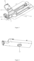
- the motion system for the vascular intervention navigation surgery system includes a support base and a vascular intervention navigation surgery system 2.
- the supporting base includes a supporting frame 1 and a base, and the base includes a C-shaped slot 14 and a connecting rod 15.
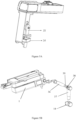
- the slider 3 is fixedly connected to the connecting female head 4 through clamping, welding, bonding, and integrated molding.
- the bottom of the vascular intervention navigation surgery system 2 is fixedly connected to the connecting male head 13 through clamping, welding, bonding, and integrated molding.
- the interior of the support frame 1 is equipped with an electric motor and a transmission structure, and the electric motor drives the slider 3 to move in a straight line on the support frame 1.
- the connecting female head 4 on the slider 3 is connected to the connecting male head 13 at the bottom of the vascular intervention navigation surgery system 2 through thread engagement and/or snap fit.
- the vascular intervention navigation surgery system 2 can move left and right in a straight line on the support frame 1.
- the induction device 5 can be laser, infrared, or mechanical.
- the vascular intervention navigation surgery system 2 includes a Y-connector platform 6, which can place and fix the Y-connector 7 and the guiding catheter connected to it.
- the front end of the Y-connector 7 is equipped with a wheel sleeve 8, which is fixedly connected coaxially with the main channel of the Y-connector 7.
- the wheel sleeve 8 is driven to rotate by the wheel sleeve driving mechanism, thereby driving the guiding catheter to rotate.
- the vascular intervention navigation surgery system 2 includes a guidewire limiting structure, which is set between the fixed plate 9 and the Y-connector platform 6.
- the guidewire limiting structure includes a positioning groove 11 and a cover plate 10.
- the positioning groove 11 is configured to accommodate the guidewire, and the positioning groove 11 corresponds to the wire groove of the fixed plate 9, jointly forming a guidewire channel for placing the guidewire;
- the cover plate 10 is equipped with one or more protruding cover pieces 12, which can be inserted into the positioning groove 11, covering the opening area of the positioning groove 11 and thereby limiting the guidewire.
- the supporting base includes a base, which is composed of a C-shaped slot 14 and a connecting rod 15, to fix the motion system of the vascular intervention navigation surgery system next to the surgical bed.
- the connecting rod 15 runs through the C-shaped slot 14, which can move up and down on the connecting rod 15 to adjust the height.
- the connecting rod 15 is connected to the support frame 1 through a hinge structure, and the support frame 1 can rotate and adjust the angle on the connecting rod 15.
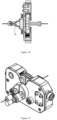
- the base comprises a first support arm 36 and a second support arm 37.
- the first support arm 36 and the supporting frame 1 are assembled together by clamping, and the second support arm 37 can be inserted into the C-shaped slot 14 for fixation.
- the second arm 37 is equipped with a slot 38, and the first arm 36 is equipped with an insertion portion 39. By inserting the insertion portion 39 into the slot 38, the fixation between the first arm 36 and the second arm 37 is achieved.
- the second arm 37 can be equipped with multiple slots 38 (shown as three in Figure 5B ), and the openings of the multiple slots 38 are facing in different directions.
- the motion system also includes a host and a handle.
- the motion parameters of the motion system are controlled through the host.
- the handle is connected to the main body signal (such as Wi-Fi, 5G, Bluetooth, etc.), and the host can be remotely controlled through the handle.
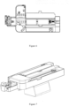
- the support frame 1 of the motion system of the vascular intervention navigation surgery system has a pair of meshing gear sets 16 at the top.
- the gear set 16 is composed of an active wheel and a passive wheel, which are driven by an electric motor.
- the bottom of the vascular intervention navigation surgery system 2 has a gear rack that matches the gear set 16. By driving the active wheel of the gear set 16 to rotate, the gear rack moves, causing the vascular intervention navigation surgery system 2 to move.
- the support frame 1 of the motion system for the vascular intervention navigation surgery system has a single gear 17 at the top, and the bottom of the vascular intervention navigation surgery system 2 has a unilateral rack 18 that is matched with the single gear 17.
- the single gear 17 By driving the single gear 17 to rotate, it drives the unilateral rack 18 to move, thereby causing the vascular intervention navigation surgery system 2 to move.
- the support frame 1 of the motion system of the vascular intervention navigation surgery system has a longitudinal gear 19 at the top, and the bottom of the vascular intervention navigation surgery system 2 has a longitudinal rack 20 that matches the longitudinal gear 19.
- the longitudinal gear 19 By driving the longitudinal gear 19 to rotate, it drives the longitudinal rack 20 to move, thereby causing the vascular intervention navigation surgery system 2 to move.
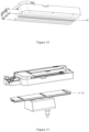
- the support frame 1 for the motion system of the vascular intervention navigation surgery system has a horizontal gear at the top, and a support platform 21 above the support frame 1.
- the bottom of the support platform 21 has a single-sided horizontal rack that matches the horizontal gear.
- the top of the support platform 21 has a magnetic suction device.
- the bottom of the vascular intervention navigation surgery system 2 has a magnetic structure 22 that is tightly attached to the support platform 21 and drives the horizontal gear to rotate, Furthermore, it drives the movement of the unilateral transverse rack, thereby causing the vascular intervention navigation surgery system to move.
- the force reproduction system for the vascular intervention navigation surgery system in this Example is shown in Figures 16-22 .
- the force reproduction system adjunct is fixed to the sun wheel 23, following the sun wheel 23 and then moving forward, backward, and rotating together with the guidewire.
- the force reproduction system adjunct of this Example includes a guidewire fixator 25, a pressure sensor, and a sliding sleeve component.
- the guidewire fixator25 is configured to clamp and fix the guidewire.
- the pressure sensor includes a pressure sensing plate 26.
- the sliding sleeve component includes a first sliding kit 27 and a second sliding kit 28. One end of the first sliding kit 27 is fixedly connected to the guidewire fixator 25. The first sliding kit 27 can slide relative to the second sliding kit 28, allowing the other end of the first sliding kit 27 to selectively press against the pressure sensing plate 26.
- the guidewire fixator 25 and the sliding sleeve component are eccentrically set, and the sliding sleeve component is coaxially set with the pressure sensor.
- the guidewire fixator 25 can be a clamp structure as shown in Figures 16-18 , a guidewire sleeve structure with high friction as shown in Figures 19-20 , and so on. There are no special restrictions on the specific structure of the guidewire fixator 25, as long as it can clamp and fix the guidewire.
- the force reproduction system adjunct may also include an electric induction magnetic coil, wherein the electric induction magnetic coil is attracted to the guidewire fixator 25 and/or the first sliding kit 27.
- the force reproduction system main end 30 includes a wheel group 31 and a simulated guidewire 32 placed between wheels of the wheel group 31, where the resistance of the wheel group 31 to the simulated guidewire 32 is equal to the resistance experienced by the guidewire during the forward process. That is to say, the resistance of the wheel group 31 to the simulated guidewire 32 is equal to the force value sensed by the pressure sensor.
- the rear end of wheel group 31 is connected to a motor, which controls the pressure between the wheels of the wheel group 31 through the rotation of the motor, that is, controls the resistance of the simulated guidewire 32 between the wheels of the wheel group 31.
- a motor which controls the pressure between the wheels of the wheel group 31 through the rotation of the motor, that is, controls the resistance of the simulated guidewire 32 between the wheels of the wheel group 31.
- the motor rotates clockwise or counterclockwise, the pressure between the wheels of the wheel group 31 will increase or decrease, and the resistance of the simulated guidewire 32 between the wheels of the wheel group 31 will increase or decrease.
- the force reproduction system main end 30 also includes a simulated pressure sensor and a main end control system.
- the simulated pressure sensor is configured to sense the operator's thrust on the simulated guidewire 32, in order to apply the thrust to the guidewire.
- the motion of the simulated guidewire 32 drives the rotation of the wheel group 31.
- the simulated pressure sensor Based on the rotation of the wheel group 31 detected by the simulated pressure sensor, it controls the forward or backward movement of the sun wheel 23, thereby driving the forward or backward movement of the guidewire.
- the conversion from the rotational motion of wheel group 31 to the forward or backward rotation angle of sun wheel group 23 to the linear distance is processed by the main end control system.
- the simulated guidewire 32 is supported by guidewire tray 33.
- the simulated guidewire 32 is connected end-to-end and is cyclically pushed.
- the guidewire tray 33 can be, but is not limited to, circular, round, or arc-shaped.
- the guidewire tray 33 has a guidewire groove 34, and the guidewire is embedded in the guidewire groove 34;
- the guidewire tray 33 is equipped with a guidewire bridge 35.
- the simulated guidewire 32 separates from the guidewire groove 34, and the operator grasps and pushes the simulated guidewire 32 at the guidewire bridge 35.
- the length of the guidewire bridge 35 is 1-20 centimeters; Preferred 3-6 centimeters.
- the diameter of the simulated guidewire 32 is 0.35 millimeters.
- the force reproduction system can combine the mechanized vascular intervention navigation surgery system with the experience of clinical doctors. When facing blood vessels with high resistance to pass, it can more effectively operate the guidewire movement and avoid damage to the patient's blood vessels, providing surgical safety.
- the experience values operated by the clinical doctors mentioned above can be numbered and classified, stored in memory for easy recall in the next similar situation, without requiring the clinical doctors to manually operate again.
Landscapes
- Health & Medical Sciences (AREA)
- Engineering & Computer Science (AREA)
- Life Sciences & Earth Sciences (AREA)
- Biomedical Technology (AREA)
- Surgery (AREA)
- Veterinary Medicine (AREA)
- General Health & Medical Sciences (AREA)
- Heart & Thoracic Surgery (AREA)
- Public Health (AREA)
- Animal Behavior & Ethology (AREA)
- Robotics (AREA)
- Medical Informatics (AREA)
- Molecular Biology (AREA)
- Nuclear Medicine, Radiotherapy & Molecular Imaging (AREA)
- Vascular Medicine (AREA)
- Cardiology (AREA)
- Transplantation (AREA)
- Oral & Maxillofacial Surgery (AREA)
- Biophysics (AREA)
- Pulmonology (AREA)
- Anesthesiology (AREA)
- Hematology (AREA)
- Media Introduction/Drainage Providing Device (AREA)
- Surgical Instruments (AREA)
Applications Claiming Priority (2)
| Application Number | Priority Date | Filing Date | Title |
|---|---|---|---|
| CN202311060465.1A CN116983091B (zh) | 2023-08-22 | 2023-08-22 | 用于血管介入导航手术系统的力复现系统 |
| CN202311457616.7A CN118593874A (zh) | 2023-11-03 | 2023-11-03 | 用于血管介入导航手术系统的运动系统 |
Publications (1)
| Publication Number | Publication Date |
|---|---|
| EP4512357A1 true EP4512357A1 (de) | 2025-02-26 |
Family
ID=90735282
Family Applications (1)
| Application Number | Title | Priority Date | Filing Date |
|---|---|---|---|
| EP24170574.8A Pending EP4512357A1 (de) | 2023-08-22 | 2024-04-16 | Bewegungssystem für gefässinterventions-navigationschirurgie |
Country Status (3)
| Country | Link |
|---|---|
| US (1) | US20250064614A1 (de) |
| EP (1) | EP4512357A1 (de) |
| JP (1) | JP7676062B2 (de) |
Citations (10)
| Publication number | Priority date | Publication date | Assignee | Title |
|---|---|---|---|---|
| US20090247943A1 (en) * | 2008-03-27 | 2009-10-01 | Kirschenman Mark B | Robotic catheter device cartridge |
| US20150073339A1 (en) * | 2013-09-06 | 2015-03-12 | Catheter Robotics Inc. | Adjustable nose cone for a catheter positioning system |
| US20160235946A1 (en) * | 2013-03-14 | 2016-08-18 | Hansen Medical, Inc. | Active drive for robotic catheter manipulators |
| CN107374737A (zh) * | 2017-07-06 | 2017-11-24 | 北京理工大学 | 一种介入手术机器人导管导丝协同操作系统及其控制方法 |
| CN109730779A (zh) * | 2019-03-07 | 2019-05-10 | 天津理工大学 | 一种血管介入手术机器人导管导丝协同控制系统及方法 |
| US20200324084A1 (en) * | 2013-10-15 | 2020-10-15 | Corindus, Inc. | Guide catheter control flexible track |
| WO2021211310A1 (en) * | 2020-04-17 | 2021-10-21 | University Of Washington | Control system for robotic catheter |
| CN113598947A (zh) | 2021-08-11 | 2021-11-05 | 介若医疗科技(上海)有限公司 | 血管介入导航手术系统 |
| CN114191082A (zh) * | 2021-12-14 | 2022-03-18 | 复旦大学 | 一种血管介入手术机器人导丝夹持与导丝阻力测定装置 |
| CN117860390A (zh) * | 2024-02-28 | 2024-04-12 | 北京唯迈医疗设备有限公司 | 一种介入机器人力反馈环形主端控制装置 |
Family Cites Families (3)
| Publication number | Priority date | Publication date | Assignee | Title |
|---|---|---|---|---|
| EP2282803B1 (de) | 2008-05-06 | 2015-07-01 | Corindus Inc. | Kathetersystem |
| US20210259794A1 (en) | 2020-02-21 | 2021-08-26 | Canon Usa, Inc. | Medical Apparatus Having Dual Manipulation Means and Methods of Use Thereof |
| WO2023016469A1 (zh) | 2021-08-11 | 2023-02-16 | 介若科技有限公司 | 手术机器人系统 |
-
2024
- 2024-04-15 US US18/635,734 patent/US20250064614A1/en active Pending
- 2024-04-15 JP JP2024065565A patent/JP7676062B2/ja active Active
- 2024-04-16 EP EP24170574.8A patent/EP4512357A1/de active Pending
Patent Citations (11)
| Publication number | Priority date | Publication date | Assignee | Title |
|---|---|---|---|---|
| US20090247943A1 (en) * | 2008-03-27 | 2009-10-01 | Kirschenman Mark B | Robotic catheter device cartridge |
| US20160235946A1 (en) * | 2013-03-14 | 2016-08-18 | Hansen Medical, Inc. | Active drive for robotic catheter manipulators |
| US20150073339A1 (en) * | 2013-09-06 | 2015-03-12 | Catheter Robotics Inc. | Adjustable nose cone for a catheter positioning system |
| US20200324084A1 (en) * | 2013-10-15 | 2020-10-15 | Corindus, Inc. | Guide catheter control flexible track |
| CN107374737A (zh) * | 2017-07-06 | 2017-11-24 | 北京理工大学 | 一种介入手术机器人导管导丝协同操作系统及其控制方法 |
| CN109730779A (zh) * | 2019-03-07 | 2019-05-10 | 天津理工大学 | 一种血管介入手术机器人导管导丝协同控制系统及方法 |
| WO2021211310A1 (en) * | 2020-04-17 | 2021-10-21 | University Of Washington | Control system for robotic catheter |
| CN113598947A (zh) | 2021-08-11 | 2021-11-05 | 介若医疗科技(上海)有限公司 | 血管介入导航手术系统 |
| WO2023015657A1 (zh) * | 2021-08-11 | 2023-02-16 | 介若医疗科技(上海)有限公司 | 血管介入导航手术系统 |
| CN114191082A (zh) * | 2021-12-14 | 2022-03-18 | 复旦大学 | 一种血管介入手术机器人导丝夹持与导丝阻力测定装置 |
| CN117860390A (zh) * | 2024-02-28 | 2024-04-12 | 北京唯迈医疗设备有限公司 | 一种介入机器人力反馈环形主端控制装置 |
Also Published As
| Publication number | Publication date |
|---|---|
| JP7676062B2 (ja) | 2025-05-14 |
| JP2025031502A (ja) | 2025-03-07 |
| US20250064614A1 (en) | 2025-02-27 |
Similar Documents
| Publication | Publication Date | Title |
|---|---|---|
| EP1755727B1 (de) | Übertragung für ein ferngesteuertes Katheterisierungssystem | |
| EP3581137B1 (de) | System zur führungskathetersteuerung | |
| US9510912B2 (en) | Module for driving a robotic catheterisation system | |
| CN113598947A (zh) | 血管介入导航手术系统 | |
| EP1442720A1 (de) | Gerät zum Manövrieren flexibler Katheter im menschlichen kardiovaskulären System | |
| CN114191092A (zh) | 一种介入手术机器人从端递送装置 | |
| CN113243978A (zh) | 穿刺装置及手术机器人 | |
| CN115414127B (zh) | 一种血管介入机器人用导管控制装置及控制方法 | |
| CN110868955A (zh) | 通过导引轨道驱动柔性细长的医疗元件的用于机器人模块的防护外罩 | |
| CN117529291A (zh) | 用于操纵细长手术工具的紧凑型机器人装置和组件 | |
| CN116999181A (zh) | 耗材盒以及手术机器人 | |
| CN114391964B (zh) | 一种紧凑型介入手术机器人驱动装置 | |
| CN115517773A (zh) | 一种导管无菌盒、导管机械臂和神经介入手术机器人 | |
| EP4512357A1 (de) | Bewegungssystem für gefässinterventions-navigationschirurgie | |
| CN115702830B (zh) | 一种介入手术导管推进机器人 | |
| CN116269796B (zh) | 一种分体式血管介入手术机器人 | |
| CN116407279A (zh) | 导丝输送装置、从端操作装置和手术机器人系统 | |
| CN218979198U (zh) | 一种齿式导管及机器人系统 | |
| CN116269791B (zh) | 一种便捷消毒的血管造影介入手术系统 | |
| CN116983091B (zh) | 用于血管介入导航手术系统的力复现系统 | |
| CN119257742B (zh) | 一种一体化手术机器人 | |
| CN221089078U (zh) | 机械臂及机器人系统 | |
| CN221732042U (zh) | 用于血管介入导航手术系统的运动系统 | |
| CN222841063U (zh) | 用于血管介入手术机器人的介入耗材执行装置 | |
| CN221534021U (zh) | 血管介入手术机器人的递送系统 |
Legal Events
| Date | Code | Title | Description |
|---|---|---|---|
| PUAI | Public reference made under article 153(3) epc to a published international application that has entered the european phase |
Free format text: ORIGINAL CODE: 0009012 |
|
| STAA | Information on the status of an ep patent application or granted ep patent |
Free format text: STATUS: THE APPLICATION HAS BEEN PUBLISHED |
|
| AK | Designated contracting states |
Kind code of ref document: A1 Designated state(s): AL AT BE BG CH CY CZ DE DK EE ES FI FR GB GR HR HU IE IS IT LI LT LU LV MC ME MK MT NL NO PL PT RO RS SE SI SK SM TR |
|
| STAA | Information on the status of an ep patent application or granted ep patent |
Free format text: STATUS: REQUEST FOR EXAMINATION WAS MADE |
|
| 17P | Request for examination filed |
Effective date: 20250718 |