EP4512352A1 - Periprothetische platte - Google Patents
Periprothetische platte Download PDFInfo
- Publication number
- EP4512352A1 EP4512352A1 EP24195678.8A EP24195678A EP4512352A1 EP 4512352 A1 EP4512352 A1 EP 4512352A1 EP 24195678 A EP24195678 A EP 24195678A EP 4512352 A1 EP4512352 A1 EP 4512352A1
- Authority
- EP
- European Patent Office
- Prior art keywords
- plate
- periprosthetic
- bone screw
- screw holes
- greater trochanter
- Prior art date
- Legal status (The legal status is an assumption and is not a legal conclusion. Google has not performed a legal analysis and makes no representation as to the accuracy of the status listed.)
- Pending
Links
Images








Classifications
-
- A—HUMAN NECESSITIES
- A61—MEDICAL OR VETERINARY SCIENCE; HYGIENE
- A61B—DIAGNOSIS; SURGERY; IDENTIFICATION
- A61B17/00—Surgical instruments, devices or methods
- A61B17/56—Surgical instruments or methods for treatment of bones or joints; Devices specially adapted therefor
- A61B17/58—Surgical instruments or methods for treatment of bones or joints; Devices specially adapted therefor for osteosynthesis, e.g. bone plates, screws or setting implements
- A61B17/68—Internal fixation devices, including fasteners and spinal fixators, even if a part thereof projects from the skin
- A61B17/80—Cortical plates, i.e. bone plates; Instruments for holding or positioning cortical plates, or for compressing bones attached to cortical plates
- A61B17/8061—Cortical plates, i.e. bone plates; Instruments for holding or positioning cortical plates, or for compressing bones attached to cortical plates specially adapted for particular bones
-
- A—HUMAN NECESSITIES
- A61—MEDICAL OR VETERINARY SCIENCE; HYGIENE
- A61B—DIAGNOSIS; SURGERY; IDENTIFICATION
- A61B17/00—Surgical instruments, devices or methods
- A61B17/56—Surgical instruments or methods for treatment of bones or joints; Devices specially adapted therefor
- A61B17/58—Surgical instruments or methods for treatment of bones or joints; Devices specially adapted therefor for osteosynthesis, e.g. bone plates, screws or setting implements
- A61B17/68—Internal fixation devices, including fasteners and spinal fixators, even if a part thereof projects from the skin
- A61B17/74—Devices for the head or neck or trochanter of the femur
- A61B17/742—Devices for the head or neck or trochanter of the femur having one or more longitudinal elements oriented along or parallel to the axis of the neck
-
- A—HUMAN NECESSITIES
- A61—MEDICAL OR VETERINARY SCIENCE; HYGIENE
- A61B—DIAGNOSIS; SURGERY; IDENTIFICATION
- A61B17/00—Surgical instruments, devices or methods
- A61B17/56—Surgical instruments or methods for treatment of bones or joints; Devices specially adapted therefor
- A61B17/58—Surgical instruments or methods for treatment of bones or joints; Devices specially adapted therefor for osteosynthesis, e.g. bone plates, screws or setting implements
- A61B17/68—Internal fixation devices, including fasteners and spinal fixators, even if a part thereof projects from the skin
- A61B17/80—Cortical plates, i.e. bone plates; Instruments for holding or positioning cortical plates, or for compressing bones attached to cortical plates
- A61B17/809—Cortical plates, i.e. bone plates; Instruments for holding or positioning cortical plates, or for compressing bones attached to cortical plates with bone-penetrating elements, e.g. blades or prongs
-
- A—HUMAN NECESSITIES
- A61—MEDICAL OR VETERINARY SCIENCE; HYGIENE
- A61B—DIAGNOSIS; SURGERY; IDENTIFICATION
- A61B17/00—Surgical instruments, devices or methods
- A61B17/56—Surgical instruments or methods for treatment of bones or joints; Devices specially adapted therefor
- A61B17/58—Surgical instruments or methods for treatment of bones or joints; Devices specially adapted therefor for osteosynthesis, e.g. bone plates, screws or setting implements
- A61B17/68—Internal fixation devices, including fasteners and spinal fixators, even if a part thereof projects from the skin
- A61B17/82—Internal fixation devices, including fasteners and spinal fixators, even if a part thereof projects from the skin for bone cerclage
Definitions
- the present disclosure generally relates to a plate to treat a long bone fracture located near an existing prosthesis that is typically at the distal or proximal femur.
- a periprosthetic fracture is a long bone fracture that occurs adjacent or around an existing prosthesis, typically at the distal or proximal femur. Due to an aging population, the frequency of these types of fractures is increasing.
- a specialized implant for the proximal femur is required to treat Vancouver Type Ag, Ag + B, and B fractures.
- a Vancouver Ag fracture is characterized by a fracture of the Greater Trochanter
- a Vancouver B fracture is characterized by a fracture of the diaphysis right around the distal tip of a prosthesis such as a hip stem.
- Treatment methods for a Vancouver B fracture include a periprosthetic proximal femur plate
- treatment methods for a Vancouver Ag +B or a Vancouver Ag fracture include a greater trochanter (“GT”) plate attached to a periprosthetic proximal femur plate.
- a greater trochanter (“GT”) plate is only used in conjunction with a periprosthetic proximal femur plate, never on its own.
- periprosthetic proximal femur plates can cause soft tissue irritation due to the thickness of the head of the plate, which sits directly below the vastus ridge of the proximal femur.
- the attachment style of the current greater trochanter (GT) plate/ periprosthetic proximal femur plate constructs yields a similar concern. Overlap of the two plates near the vastus ridge area results in a prominent plate construct thickness which can cause soft tissue irritation.
- GT current greater trochanter
- a hook segment is a plate with hooks intended to go around the tip of the greater trochanter and is secured with screws.
- Current hook segment designs can have properties that are not ideal for this indication. This includes but is not limited to: 1) Too thick medial to lateral, which can cause patient discomfort; 2) insufficient screw options to properly secure the fracture fragments; and 3) screws not targeted to engage desired bony anatomy.
- a periprosthetic plate that is less intrusive to increase patient comfort, provides screw options to properly secure fracture fragments, and engages bony anatomy.
- a periprosthetic plate that includes a proximal segment having a top portion and an end portion with at least two curved hooks that are capable of passing through a patient's abductor muscles and rest medially on the tip of a patient's greater trochanter (GT), wherein the proximal segment includes a plurality of recessed bone screw holes for attachment to a patient's femur with bone screws.
- GT greater trochanter
- the proximal segment includes a hook portion having at least two curved hooks and an attachment portion.
- a further object, feature, and/or advantage of the present disclosure is that the plurality of recessed bone screw holes are recessed so that any inserted bone screws do not extend above the top portion of the proximal segment.
- An aspect of the present disclosure is that the plurality of recessed bone screw holes are in sets of two recessed bone screw holes parallel to each other.
- Another aspect of the present disclosure is a distal segment or shaft that is attached to or is integral with the proximal segment.
- proximal segment includes a hook segment attached to at least two curved hooks and an attachment segment.
- the hook segment includes a first plurality of recessed bone screw holes
- the attachment segment includes a second plurality of recessed bone screw holes
- the distal segment or shaft includes a third plurality of recessed bone screw holes.
- first plurality of recessed bone screw holes are in sets of two and parallel to each other
- second plurality of recessed bone screw holes are in sets of two and parallel to each other
- third plurality of recessed bone screw holes are staggered from side-to-side along the longitudinal length of the distal segment or shaft.
- yet another feature of the present disclosure is the first plurality of recessed bone screw holes, the second plurality of recessed bone screw holes, and the third plurality of recessed bone screw holes are recessed so that any inserted bone screws do not extend above the top portion of the proximal segment.
- proximal segment includes at least one cerclage cable hole set that can receive at least one cerclage cable.
- another aspect of the present disclosure is at least one cerclage crimp located in an opening in the proximal segment.
- proximal segment includes at least one cerclage cable set that can each receive a cerclage cable and at least one cerclage crimp located in at least one opening in the proximal segment.
- a periprosthetic plate that includes a hook segment having a top portion and an end portion with at least two curved hooks that are capable of passing through a patient's abductor muscles and rest medially on a tip of a patient's greater trochanter (GT), wherein the hook segment includes a first plurality of recessed bone screw holes that are recessed so that any inserted bone screws do not extend above the top portion of the hook segment and are in sets of two recessed bone screw holes that are parallel to each other, and an attachment segment that is attached or integral to the hook segment and includes a second plurality of recessed bone screw holes that are in sets of two and parallel to each other and beveled so that any inserted bone screws do not extend above the top portion of the hook segment and are in sets of two recessed bone screw holes that are parallel to each other.
- GT patient's greater trochanter
- yet another feature of the present disclosure is a distal segment or shaft that is attached to or integral with the attachment segment and includes a third plurality of recessed bone screw holes that are staggered from side-to-side along the length of the distal segment or shaft, wherein the third plurality of recessed bone screw holes are beveled so that any inserted bone screws do not extend above the top portion of the proximal segment.
- Another aspect of the present disclosure is a method utilizing a periprosthetic plate that includes securing a proximal segment into a patient having a top portion and an end portion with at least two curved hooks through a patient's abductor muscles that rest medially on a tip of a patient's greater trochanter (GT) by inserting bone screws into a first plurality of recessed bone screw holes but avoiding existing prosthesis or intramedullary nail, wherein the inserted bone screws do not extend above the top portion of the proximal segment.
- GT greater trochanter
- An additional feature of the disclosure is a method for securing a distal segment or shaft that is attached to or integral with the proximal segment by inserting bone screws into a second plurality of recessed bone screw holes wherein the inserted bone screws do not extend above the top portion of the distal segment or shaft.
- Yet another feature of the method of the present disclosure is inserting bone screws into the second plurality of recessed bone screw holes that are staggered from side-to-side along the length of the distal segment or shaft.
- It is still yet another feature of the method of the present disclosure is inserting at least one cerclage cable through a plurality of holes in the proximal segment to secure the patient's bone.
- It still another feature of the method of the present disclosure is applying tension to at least one cerclage cable and then securing the at least one cerclage cable with a cerclage crimp located in an opening within the proximal segment.
- a periprosthetic proximal femur plate that includes a head portion having a plurality of first polyaxial screw holes, and a shaft portion, having a first lateral plate edge and second lateral plate edge, connected to the head portion having a plurality of rows of second polyaxial screw holes located at an angle from a first lateral plate edge and a second lateral plate edge of about thirty degrees to about seventy degrees.
- first and second polyaxial screw holes have a cone of angulation in a range from about twenty-five degrees to about forty-five degrees.
- Still another aspect of the present disclosure is wherein the first and second polyaxial screw holes have a cone of angulation in a range from about thirty degrees to about forty degrees.
- An aspect of the present disclosure is the plurality of rows of the second polyaxial screw holes includes at least three rows.
- the second polyaxial screw holes include a series of second polyaxial screw holes in a three-hole pattern.
- Another feature of the present disclosure is the plurality of rows of polyaxial screw holes are located at an angle from the first lateral plate edge and the second lateral plate edge of about forty degrees to about sixty degrees.
- Yet another aspect of the present disclosure is the plurality of rows of second polyaxial screw holes are located at an angle from the first lateral plate edge and the second lateral plate edge of about thirty-five degrees to about fifty-five degrees.
- the head portion includes at least one orientation feature and at least one screw hole for connection with another plate.
- Still another aspect of the present disclosure is at least one polyaxial screw hole for accepting an articulated tension device (ATD) located at the end of the shaft portion of the periprosthetic proximal femur plate.
- ATD articulated tension device
- a further feature of the disclosure is a combination periprosthetic proximal femur plate and greater trochanter (GT) plate construct that includes a periprosthetic proximal femur plate having a first lateral plate edge, a second lateral plate edge, and a head portion having a plurality of first polyaxial screw holes and a shaft portion connected to the head portion and having a plurality of rows of second polyaxial screw holes located at an angle from the first lateral plate edge and the second lateral plate edge of about thirty degrees to about seventy degrees, and a greater trochanter (GT) plate located on top of the periprosthetic proximal femur plate having a base portion with a plurality of third clearance screw holes that are aligned with the plurality of second polyaxial screw holes in the periprosthetic proximal femur plate and having a first arm and a second arm attached to the base portion and extending outward to wrap around a patient's greater trochanter (GT).
- GT
- a portion of the periprosthetic proximal femur plate includes a portion of the periprosthetic proximal femur plate is uncovered from the greater trochanter (GT) plate, with at least one first polyaxial screw hole being visible or covered with no axial screw holes being visible.
- GT trochanter
- yet another feature of the present disclosure is a plurality of k-wire/suture openings in both the periprosthetic proximal femur plate and the greater trochanter (GT) plate.
- the first arm includes a plurality of fourth polyaxial screw holes
- the second arm includes a plurality of fifth polyaxial screw holes.
- It is still yet another feature of the method of the present disclosure is a plurality of cylindrical recesses in the head portion of the periprosthetic proximal femur plate for receiving a plurality of downward cylindrical protrusions of the greater trochanter (GT) plate with a plurality of threaded openings in both the periprosthetic proximal femur plate and the greater trochanter (GT) plate located in the middle of the plurality of cylindrical protrusions to secure together with a plurality of threaded bolts.
- GT greater trochanter
- Yet another aspect of the present disclosure includes at least one slot in the head portion of the periprosthetic proximal femur plate for receiving a downward protruding angled bar of the greater trochanter (GT) plate and a cylindrical recess in the head portion of the periprosthetic proximal femur plate for receiving a downward cylindrical protrusion with a threaded opening located in the middle of the cylindrical protrusion that can secure together the periprosthetic proximal femur plate and the greater trochanter (GT) plate with a threaded bolt.
- GT greater trochanter
- It still another feature of the method of the present disclosure is of utilizing a combination periprosthetic proximal femur plate and greater trochanter (GT) plate construct, that includes inserting bone screws into a plurality of first polyaxial screw holes of a periprosthetic proximal femur plate having a head portion, a first lateral plate edge, and a second lateral plate edge, inserting bone screws into a plurality of rows of second polyaxial screw holes located in a shaft portion connected to the head portion, wherein the plurality of rows of second polyaxial screw holes located at an angle from the first lateral plate edge and the second lateral plate edge of about thirty degrees to about seventy degrees, and inserting bone screws into a plurality of third clearance screw holes located in a base portion of a greater trochanter (GT) plate located on top of the periprosthetic proximal femur plate, wherein the plurality of third clearance screw holes that are aligned with the plurality of second polyaxial screw holes in the peripros
- It is yet another feature of the method of the present disclosure includes utilizing a combination periprosthetic proximal femur plate and greater trochanter (GT) plate construct and inserting an articulated tension device (ATD) located at an end of the shaft portion of the periprosthetic proximal femur plate.
- GT trochanter
- a periprosthetic plate is generally indicated by the numeral 10.
- This periprosthetic plate 10 that includes a distal segment or shaft 12 and a proximal segment 14.
- This periprosthetic plate 10 may or may not include the distal segment or shaft 12.
- the version without a distal segment or shaft 12 is intended for simple Ag fractures. It will also be available in multiple sizes to match greater trochanter (GT) 40 anatomies (shown in FIG. 5 ) of a variety of patients.
- GT trochanter
- the periprosthetic plate 10 can have multiple lengths of the distal segment or shaft 12, with the longest able to span the entire femur bone of the patient.
- the bone plates use biocompatible materials such as stainless steel (SS), cobalt base alloys, titanium alloys, bioceramics, composite materials, pure titanium, composite materials, and non-resorbable and bioresorbable polymers. These materials fall into a category such as bioinert, bioactive, bioresorbale, and porous.
- bioinert material is utilized for bone plates because if the bioactive material gets bonded to the bone or other soft tissues, there can be issues if bone plate removal or corrective surgery is required.
- the thickness of the bone plate depends on the specific material utilized and the type of patient bone, and potentially the specific anatomy of the patient.
- the distal segment or shaft 12 includes holes 16 that are preferably beveled.
- the optimal depth of the distal segment or shaft 12 is only of a height that is slightly higher than the head of a bone screw 11, shown in FIG. 5 , to minimize patient discomfort.
- the holes 16 are located in an alternating arrangement to minimize distance along the distal segment or shaft 12 that does not include a bone screw 11 and to ensure both sides of the distal segment or shaft 12 are secured to a bone.
- the proximal segment 14 includes an attachment segment 13 and a hook segment 15 connected together or preferably integral.
- hook segment 15 also includes a series of holes 20.
- the periprosthetic plate 10 may be positioned laterally or posterolaterally, with the hook(s) 22 passing through the abductor muscles of the patient and resting medially to the tip of the greater trochanter (GT) 40.
- the periprosthetic plate 10 is tensioned to reduce a bone fracture.
- screws are placed through holes 16, 18, and 20 in the periprosthetic plate 10 into the greater trochanter (GT) 40 of a patient.
- GT trochanter
- the position of the periprosthetic plate 10 is shown in relation to the greater trochanter (GT) 40, lesser trochanter 42, and prosthesis 44.
- the bone screws 11 in the greater trochanter (GT) 40 are positioned to achieve two results. First, the bone screws 11 must not interfere with the existing prosthesis 44 or intramedullary nail (IM) (not shown), which passes through the greater trochanter (GT) 40 into the medullary canal.
- IM intramedullary nail
- the nominal (co-axial with the hole) screw hole 16, 18, and 20 trajectories must target the areas of the proximal femur with the best (densest) bone.
- This bone is typically around the lesser trochanter (LT) 42; therefore, two posterior bone screws 11 are targeted to the lesser trochanter (LT) 42 area.
- the quality of the anterior bone of the greater trochanter (GT) 40 will vary according to the fracture and patient, but still requires the placement of bone screws 11. There is a minimum of four bone screws 11 in the greater trochanter (GT) 40 with two anterior and two posteriors.
- At least one cable 52 may be passed through at least one cerclage crimp 50, which lay recessed along the center 31 of the top the periprosthetic plate 10, as shown in FIG. 6 . Once tensioned, the at least one crimp 50 can be deformed to secure the at least one cable 52.
- a first pair of grooves 30 and a second pair of grooves 32 on each side of the opening in an opening in a center 31 of the top of the periprosthetic plate 10 could, in the alternative, also be grooves/recesses along the top (lateral side) of the periprosthetic plate 10 instead of holes thru the plate. Either are intended to maintain the position of the cerclage cable after tensioning.
- aspects of this technology disclosed include the thickness of the periprosthetic plate 10 across the lateral greater trochanter (GT) 40 is minimized to reduce prominence.
- the bone screw 11 trajectories are optimized to target the densest bone.
- the bone screws 11 are placed to avoid interference with the prosthesis 44.
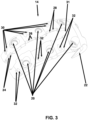
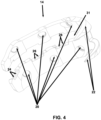
- hook segment 15 without the distal segment or shaft 12 may be optionally designed such that a portion of the hook segment 15 distal to the vastus ridge is not connected, as shown in FIGS. 3 and 4 . Because they are not connected, the anterior, shown in FIG. 3 , and posterior segments, shown in FIG. 4 , of periprosthetic plate 10 can be individually contoured to match a patient's respective anatomies.
- a periprosthetic plate is a periprosthetic proximal femur plate, generally indicated by numeral 54 in FIG. 8 , that is located on a patient's femur bone 56.
- the periprosthetic proximal femur plate 54 is designed to sit below the vastus ridge of the femur bone 56 and has a thinner chamfered proximal end 58 to reduce soft tissue irritation where the shaft of the periprosthetic proximal femur plate 54 gets gradually thinner in the distal portion 60.
- This thinner distal portion 60 allows for easier bending of the periprosthetic proximal femur plate 54 to better conform to the condyles when desired, which are the points of articulation and rotation at the end of the femur bone 56.
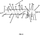
- the periprosthetic proximal femur plate 54 is shown from a top view.
- the head of the periprosthetic proximal femur plate 54 is generally indicated by the numeral 62.
- the head 62 can include eight bone screw holes. This includes a first head bone screw hole 64, a second head bone screw hole 66, a third head bone screw hole 68, a fourth head bone screw hole 70, a fifth head bone screw hole 72, a sixth head bone screw hole 74, a seventh head bone screw hole 76, and an eighth head bone screw hole 78.
- all of the head bone screw holes 62, 64, 66, 68, 70, 72, 74, 76, and 78 can be 3.5-millimeter screw holes with a forty-degree cone of angulation.
- An alternative embodiment is to have four to six of the head bone screw holes be 4.5-millimeter polyaxial screw holes with a thirty-degree cone of angulation with only the seventh head bone screw hole 76 and the eighth head bone screw hole 78 at the proximal end of the head 62 being 3.5-millimeter screw holes with a forty-degree cone of angulation.
- the cone of angulation can range from zero to thirty degrees for a 4.5-millimeter polyaxial screw and zero to forty degrees, for a 3.5-millimeter polyaxial screw.
- GT greater trochanter
- GT greater trochanter
- slotted orientation feature for a greater trochanter (GT) plate 86 can be a variety of shapes, preferably rectangular or circular.
- k-wire/suture holes 80 at the proximal tip and along the sides of the periprosthetic proximal femur plate 54.
- the shaft of the periprosthetic proximal femur plate 54 is generally indicated by the numeral 88. There is a first lateral plate edge 79 and a second lateral plate edge 81.
- the periprosthetic proximal femur plate 54 is just considered one length of plate 54. There will be multiple lengths available ranging from 119 millimeters to 388 millimeters in, at most around 35-millimeter increments. There are a variety of bone screw holes to be located with the shaft 88 in a variety of patterns.
- This combination construct 160 of proximal femur plate 54 and greater trochanter (GT) plate 116 provides significant advantages over the prior art that overlaps right below the vastus ridge where the plate overlap increases the construct 160 thickness and could cause the construct 160 to protrude above the vastus ridge which may increase the risk for soft tissue irritation and patient discomfort and potentially lead to revision surgery.
- GT trochanter
- the greater trochanter (GT) plate 116 includes clearance holes for the k-wire/suture holes 80 that can also include locating the k-wire/suture holes 80 in between the screw holes 128, 130, 132, 134, 136, and 138 for suturing through the greater trochanter (GT) plate 116.
- Another feature is the seventh and eighth polyaxial screw holes 76 and 78 in the periprosthetic proximal femur plate 54.
- FIG. 11 a side view of the greater trochanter (GT) 40 is shown, including the apex 162 of the greater trochanter (GT) 40.
- the ridges or eyebrows 126 on the top surface of the trochanter (GT) plate 40 are also shown, as well as the uncovered portion of the periprosthetic proximal femur plate 54.
- FIG. 12 in a first embodiment that is generally indicated by the numeral 161, there are a first partially threaded bolt 164 and a second partially threaded bolt 166.
- a slanted rod 168 in the greater trochanter (GT) plate 116 that slides into the slotted orientation feature 86, shown in FIG. 9 , in the periprosthetic proximal femur plate 54 for proper orientation.
- the slanted rod 168 is pointed upwards proximally in order to help resist the tension forces being exerted by the abductors.
- GT greater trochanter
- the threads 172 and 173 in the greater trochanter (GT) plate 116 allow the bolts, e.g., M5 X 0.8 bolts, to be pre-assembled and retained within the greater trochanter (GT) plate 116.
- the first partially threaded bolt 164 and a second partially threaded bolt 166 are partially threaded to allow the greater trochanter (GT) plate 116 and the threads 170 and171, respectively, in periprosthetic proximal femur plate 54 to be oriented properly prior to connecting them.
- GT trochanter
- the first partially threaded bolt 164 is positioned within the first threaded hole in the periprosthetic proximal femur plate for the GT plate connection 82, and the first threaded hole in the GT plate for the periprosthetic proximal femur plate connection 122 with threads 170 in the periprosthetic proximal femur plate 54 and threads 172 in the greater trochanter (GT) plate 116.
- GT trochanter
- the second partially threaded bolt 166 is positioned within the second threaded hole in the periprosthetic proximal femur plate for GT plate connection 84, and the second threaded hole in the GT plate for periprosthetic proximal femur plate connection 124 with threads 171 in the periprosthetic proximal femur plate 54 and threads 173 in the greater trochanter (GT) plate 116.
- GT trochanter
- the second embodiment of connecting the trochanter (GT) plate to the periprosthetic proximal femur plate is generally indicated by numeral 174 in FIG. 13 .
- the threads 172 and 173 in the greater trochanter (GT) plate 116 allow the bolts, e.g., M5 X 0.8 bolts, to be pre-assembled and retained within the greater trochanter (GT) plate 116.
- the first partially threaded bolt 164 and a second partially threaded bolt 166 are partially threaded to allow the greater trochanter (GT) plate 116 and the threads 170 and 171, respectively, in periprosthetic proximal femur plate 54 to be oriented properly prior to connecting them.
- GT trochanter
- the first partially threaded bolt 164 is positioned within the first threaded hole 170 in the periprosthetic proximal femur plate 82 and the first threaded hole in the GT plate for periprosthetic proximal femur plate connection 122 with threads 172.
- the second partially threaded bolt 166 is positioned within the second threaded hole 171 in the periprosthetic proximal femur plate 84 and the second threaded hole in the GT plate for periprosthetic proximal femur plate connection 124 with threads 173.
- connection is made through greater trochanter (GT) plate cylindrical boss protrusions 178 that are located around the threaded connections 172 in the greater trochanter (GT) plate 116 that also function as orientation features.
- GT greater trochanter
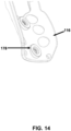
- These cylindrical boss protrusions 178 on the underside of the greater trochanter (GT) plate 116 key into the cylindrical recesses 176 in the periprosthetic proximal femur plate 54.
- An advantage to this second embodiment 174 is that the heads of the partially threaded bolts 164 and 166 can be lower compared to the first embodiment 161.
- FIG. 14 the cylindrical boss protrusions 178 on the underside of the greater trochanter (GT) plate 116 are more clearly shown.
- FIG. 15 the cylindrical recesses 176 in the periprosthetic proximal femur plate 54 are more clearly shown.
- the third embodiment includes a slimmer profile than the first embodiment, and the second embodiment of connecting the trochanter (GT) plate 116 to the periprosthetic proximal femur plate 54 and is generally indicated by the numeral 180.
- the connection mechanism has one threaded connection and two orientation features. Referring now to FIG. 16 , there is the second partially threaded bolt 166 that can be received within the threads 173 located in the greater trochanter (GT) plate 116.
- the threads 173 in the greater trochanter (GT) plate 116 allow the bolts, e.g., M5 X 0.8 bolts, to be pre-assembled and retained within the greater trochanter (GT) plate 116.
- This second partially threaded bolt 166 is partially threaded to allow the greater trochanter (GT) plate 116 and the threads 171 in periprosthetic proximal femur plate 54 to be oriented properly prior to connecting them.
- the connection is made through greater trochanter (GT) plate cylindrical boss protrusions 178 that are located around the threaded connections 173 in the greater trochanter (GT) plate 116 that also function as orientation features.
- This cylindrical boss protrusion 178 on the underside of the greater trochanter (GT) plate 116 key into the cylindrical recess 176 in the periprosthetic proximal femur plate 54.
- the slanted rod 168 is pointed upwards proximally in order to help resist the tension forces being exerted by the abductors. This offers a mechanical advantage in terms of the stability of the combination of greater trochanter (GT) plate and periprosthetic proximal femur plate construct 160.
- GT trochanter
- the plate bolt attachment hole 124 is shown in greater detail on the periprosthetic proximal femur plate 54.
- Table 1 List of Reference Characters 10 Periprosthetic plate 11 Bone screw 12 Distal segment or shaft 13 Attachment segment 14 Proximal segment 15 Hook segment 16 Holes for the distal plate or shaft 18 Holes for the attachment segment 20 Holes for the hook segment 22 Hooks 24 First set of cable holes 26 Second set of cable holes 28 Third set of cable holes 30 First pair of grooves 31 Opening in the center of the top of the periprosthetic plate 32 Second pair of grooves 40 Greater trochanter (GT) 42 Lesser trochanter 44 Prosthesis 50 Cerclage crimp 52 Cerclage cable 54 Periprosthetic proximal femur plate 56 Femur bone 58 Thinner chamfered proximal end portion of the periprosthetic proximal femur plate positioned below
- exemplary refers to an example, an instance, or an illustration, and does not indicate a most preferred embodiment unless otherwise stated.
- substantially refers to a great or significant extent. “Substantially” can thus refer to a plurality, majority, and/or a supermajority of said quantifiable variables, given proper context.
- the term “configured” describes structure capable of performing a task or adopting a particular configuration.
- the term “configured” can be used interchangeably with other similar phrases, such as constructed, arranged, adapted, manufactured, and the like.
Landscapes
- Health & Medical Sciences (AREA)
- Orthopedic Medicine & Surgery (AREA)
- Surgery (AREA)
- Life Sciences & Earth Sciences (AREA)
- Heart & Thoracic Surgery (AREA)
- Nuclear Medicine, Radiotherapy & Molecular Imaging (AREA)
- Engineering & Computer Science (AREA)
- Biomedical Technology (AREA)
- Neurology (AREA)
- Medical Informatics (AREA)
- Molecular Biology (AREA)
- Animal Behavior & Ethology (AREA)
- General Health & Medical Sciences (AREA)
- Public Health (AREA)
- Veterinary Medicine (AREA)
- Surgical Instruments (AREA)
Applications Claiming Priority (1)
| Application Number | Priority Date | Filing Date | Title |
|---|---|---|---|
| US18/454,870 US20250064490A1 (en) | 2023-08-24 | 2023-08-24 | Periprosthetic plate and associated method of use |
Publications (1)
| Publication Number | Publication Date |
|---|---|
| EP4512352A1 true EP4512352A1 (de) | 2025-02-26 |
Family
ID=92503877
Family Applications (1)
| Application Number | Title | Priority Date | Filing Date |
|---|---|---|---|
| EP24195678.8A Pending EP4512352A1 (de) | 2023-08-24 | 2024-08-21 | Periprothetische platte |
Country Status (3)
| Country | Link |
|---|---|
| US (2) | US20250064491A1 (de) |
| EP (1) | EP4512352A1 (de) |
| JP (1) | JP2025031658A (de) |
Cited By (2)
| Publication number | Priority date | Publication date | Assignee | Title |
|---|---|---|---|---|
| USD1099319S1 (en) * | 2024-06-07 | 2025-10-21 | Stryker European Operations Limited | Bone plate |
| USD1118930S1 (en) * | 2024-06-07 | 2026-03-17 | Stryker European Operations Limited | Bone plate |
Families Citing this family (1)
| Publication number | Priority date | Publication date | Assignee | Title |
|---|---|---|---|---|
| USD1101150S1 (en) * | 2024-01-17 | 2025-11-04 | In2Bones, LLC | Bone hook plate |
Citations (5)
| Publication number | Priority date | Publication date | Assignee | Title |
|---|---|---|---|---|
| US20060235401A1 (en) * | 2000-02-03 | 2006-10-19 | Pioneer Laboratories, Inc. | Apparatus and method for repairing the femur |
| WO2010061410A1 (en) * | 2008-11-25 | 2010-06-03 | Intrauma S.R.L | Modular osteosynthesis hook plate |
| US20100234896A1 (en) * | 2006-08-15 | 2010-09-16 | Kai-Uwe Lorenz | Trochanter retention plate |
| US20140243907A1 (en) * | 2013-02-27 | 2014-08-28 | Biomet C.V. | Periprosthetic Fracture Repair System Including Discrete Stabilized Crimp Lugs for Cerclage Cable and Tool Therefor |
| US20220061897A1 (en) * | 2020-08-25 | 2022-03-03 | DePuy Synthes Products, Inc. | Bone plating system clamp sizing instrument and installation instrument |
Family Cites Families (5)
| Publication number | Priority date | Publication date | Assignee | Title |
|---|---|---|---|---|
| US6228085B1 (en) * | 1998-07-14 | 2001-05-08 | Theken Surgical Llc | Bone fixation system |
| CA2643678C (en) * | 2008-06-12 | 2016-01-19 | Socovar, Societe En Commandite | Orthopaedic fixation component and method |
| US8808333B2 (en) * | 2009-07-06 | 2014-08-19 | Zimmer Gmbh | Periprosthetic bone plates |
| US11197682B2 (en) * | 2015-08-27 | 2021-12-14 | Globus Medical, Inc. | Proximal humeral stabilization system |
| CA3056417A1 (en) * | 2017-03-13 | 2018-09-20 | DePuy Synthes Products, Inc. | Proximal femur plate system |
-
2023
- 2023-08-24 US US18/454,900 patent/US20250064491A1/en active Pending
- 2023-08-24 US US18/454,870 patent/US20250064490A1/en active Pending
-
2024
- 2024-08-21 EP EP24195678.8A patent/EP4512352A1/de active Pending
- 2024-08-22 JP JP2024140660A patent/JP2025031658A/ja active Pending
Patent Citations (5)
| Publication number | Priority date | Publication date | Assignee | Title |
|---|---|---|---|---|
| US20060235401A1 (en) * | 2000-02-03 | 2006-10-19 | Pioneer Laboratories, Inc. | Apparatus and method for repairing the femur |
| US20100234896A1 (en) * | 2006-08-15 | 2010-09-16 | Kai-Uwe Lorenz | Trochanter retention plate |
| WO2010061410A1 (en) * | 2008-11-25 | 2010-06-03 | Intrauma S.R.L | Modular osteosynthesis hook plate |
| US20140243907A1 (en) * | 2013-02-27 | 2014-08-28 | Biomet C.V. | Periprosthetic Fracture Repair System Including Discrete Stabilized Crimp Lugs for Cerclage Cable and Tool Therefor |
| US20220061897A1 (en) * | 2020-08-25 | 2022-03-03 | DePuy Synthes Products, Inc. | Bone plating system clamp sizing instrument and installation instrument |
Cited By (2)
| Publication number | Priority date | Publication date | Assignee | Title |
|---|---|---|---|---|
| USD1099319S1 (en) * | 2024-06-07 | 2025-10-21 | Stryker European Operations Limited | Bone plate |
| USD1118930S1 (en) * | 2024-06-07 | 2026-03-17 | Stryker European Operations Limited | Bone plate |
Also Published As
| Publication number | Publication date |
|---|---|
| US20250064491A1 (en) | 2025-02-27 |
| US20250064490A1 (en) | 2025-02-27 |
| JP2025031658A (ja) | 2025-03-07 |
Similar Documents
| Publication | Publication Date | Title |
|---|---|---|
| US20250064491A1 (en) | Periprosthetic plate and associated method of use | |
| US8808333B2 (en) | Periprosthetic bone plates | |
| EP0471418B1 (de) | Komponenten eines Modulsystems zum Fixieren des Femurs | |
| EP3595556B1 (de) | Proximales femurplattensystem | |
| US8118848B2 (en) | Orthopedic plate for use in fibula repair | |
| EP2355730B1 (de) | Schlüsselbeinplatte und schrauben | |
| US7771457B2 (en) | Orthopedic plate for use in small bone repair | |
| AU2020100666A4 (en) | Osteotomy Guide Plate | |
| US8403966B2 (en) | Clavicle plate and screws | |
| JP2025156423A (ja) | 肩峰鎖骨フックプレート | |
| US11224469B2 (en) | Implants and related methods for bunion correction | |
| CN114513996B (zh) | 假体周围骨板系统 | |
| EP4153078B1 (de) | Periprothetische knochenplatte | |
| US12599417B2 (en) | Patella bone plate systems | |
| RU2860631C1 (ru) | Фиксатор большого вертела при эндопротезировании тазобедренного сустава | |
| CN115461004B (en) | Bone plate around prosthesis | |
| JP2024506492A (ja) | プロテーゼ周囲骨プレートのための標的化システム | |
| WO2026029840A1 (en) | Systems, implants and related methods for bunion correction |
Legal Events
| Date | Code | Title | Description |
|---|---|---|---|
| PUAI | Public reference made under article 153(3) epc to a published international application that has entered the european phase |
Free format text: ORIGINAL CODE: 0009012 |
|
| STAA | Information on the status of an ep patent application or granted ep patent |
Free format text: STATUS: REQUEST FOR EXAMINATION WAS MADE |
|
| 17P | Request for examination filed |
Effective date: 20240821 |
|
| AK | Designated contracting states |
Kind code of ref document: A1 Designated state(s): AL AT BE BG CH CY CZ DE DK EE ES FI FR GB GR HR HU IE IS IT LI LT LU LV MC ME MK MT NL NO PL PT RO RS SE SI SK SM TR |
|
| STAA | Information on the status of an ep patent application or granted ep patent |
Free format text: STATUS: EXAMINATION IS IN PROGRESS |
|
| 17Q | First examination report despatched |
Effective date: 20260220 |