EP4512282A1 - Messegerät - Google Patents
Messegerät Download PDFInfo
- Publication number
- EP4512282A1 EP4512282A1 EP23894773.3A EP23894773A EP4512282A1 EP 4512282 A1 EP4512282 A1 EP 4512282A1 EP 23894773 A EP23894773 A EP 23894773A EP 4512282 A1 EP4512282 A1 EP 4512282A1
- Authority
- EP
- European Patent Office
- Prior art keywords
- illumination
- show case
- accommodation space
- color
- image
- Prior art date
- Legal status (The legal status is an assumption and is not a legal conclusion. Google has not performed a legal analysis and makes no representation as to the accuracy of the status listed.)
- Pending
Links
Images


Classifications
-
- A—HUMAN NECESSITIES
- A47—FURNITURE; DOMESTIC ARTICLES OR APPLIANCES; COFFEE MILLS; SPICE MILLS; SUCTION CLEANERS IN GENERAL
- A47F—SPECIAL FURNITURE, FITTINGS, OR ACCESSORIES FOR SHOPS, STOREHOUSES, BARS, RESTAURANTS OR THE LIKE; PAYING COUNTERS
- A47F3/00—Show cases or show cabinets
- A47F3/001—Devices for lighting, humidifying, heating, ventilation
-
- A—HUMAN NECESSITIES
- A47—FURNITURE; DOMESTIC ARTICLES OR APPLIANCES; COFFEE MILLS; SPICE MILLS; SUCTION CLEANERS IN GENERAL
- A47F—SPECIAL FURNITURE, FITTINGS, OR ACCESSORIES FOR SHOPS, STOREHOUSES, BARS, RESTAURANTS OR THE LIKE; PAYING COUNTERS
- A47F11/00—Arrangements in shop windows, shop floors or show cases
- A47F11/06—Means for bringing about special optical effects
- A47F11/10—Arrangements of light sources
-
- A—HUMAN NECESSITIES
- A47—FURNITURE; DOMESTIC ARTICLES OR APPLIANCES; COFFEE MILLS; SPICE MILLS; SUCTION CLEANERS IN GENERAL
- A47F—SPECIAL FURNITURE, FITTINGS, OR ACCESSORIES FOR SHOPS, STOREHOUSES, BARS, RESTAURANTS OR THE LIKE; PAYING COUNTERS
- A47F3/00—Show cases or show cabinets
- A47F3/004—Show cases or show cabinets adjustable, foldable or easily dismountable
-
- A—HUMAN NECESSITIES
- A47—FURNITURE; DOMESTIC ARTICLES OR APPLIANCES; COFFEE MILLS; SPICE MILLS; SUCTION CLEANERS IN GENERAL
- A47F—SPECIAL FURNITURE, FITTINGS, OR ACCESSORIES FOR SHOPS, STOREHOUSES, BARS, RESTAURANTS OR THE LIKE; PAYING COUNTERS
- A47F3/00—Show cases or show cabinets
- A47F3/005—Show cases or show cabinets with glass panels
-
- A—HUMAN NECESSITIES
- A47—FURNITURE; DOMESTIC ARTICLES OR APPLIANCES; COFFEE MILLS; SPICE MILLS; SUCTION CLEANERS IN GENERAL
- A47F—SPECIAL FURNITURE, FITTINGS, OR ACCESSORIES FOR SHOPS, STOREHOUSES, BARS, RESTAURANTS OR THE LIKE; PAYING COUNTERS
- A47F3/00—Show cases or show cabinets
- A47F3/10—Rotary show cases or cabinets
-
- F—MECHANICAL ENGINEERING; LIGHTING; HEATING; WEAPONS; BLASTING
- F21—LIGHTING
- F21V—FUNCTIONAL FEATURES OR DETAILS OF LIGHTING DEVICES OR SYSTEMS THEREOF; STRUCTURAL COMBINATIONS OF LIGHTING DEVICES WITH OTHER ARTICLES, NOT OTHERWISE PROVIDED FOR
- F21V33/00—Structural combinations of lighting devices with other articles, not otherwise provided for
-
- H—ELECTRICITY
- H04—ELECTRIC COMMUNICATION TECHNIQUE
- H04N—PICTORIAL COMMUNICATION, e.g. TELEVISION
- H04N21/00—Selective content distribution, e.g. interactive television or video on demand [VOD]
- H04N21/40—Client devices specifically adapted for the reception of or interaction with content, e.g. set-top-box [STB]; Operations thereof
- H04N21/41—Structure of client; Structure of client peripherals
- H04N21/422—Input-only peripherals, i.e. input devices connected to specially adapted client devices, e.g. global positioning system [GPS]
- H04N21/4223—Cameras
-
- H—ELECTRICITY
- H05—ELECTRIC TECHNIQUES NOT OTHERWISE PROVIDED FOR
- H05B—ELECTRIC HEATING; ELECTRIC LIGHT SOURCES NOT OTHERWISE PROVIDED FOR; CIRCUIT ARRANGEMENTS FOR ELECTRIC LIGHT SOURCES, IN GENERAL
- H05B45/00—Circuit arrangements for operating light-emitting diodes [LED]
- H05B45/10—Controlling the intensity of the light
-
- H—ELECTRICITY
- H05—ELECTRIC TECHNIQUES NOT OTHERWISE PROVIDED FOR
- H05B—ELECTRIC HEATING; ELECTRIC LIGHT SOURCES NOT OTHERWISE PROVIDED FOR; CIRCUIT ARRANGEMENTS FOR ELECTRIC LIGHT SOURCES, IN GENERAL
- H05B45/00—Circuit arrangements for operating light-emitting diodes [LED]
- H05B45/20—Controlling the colour of the light
-
- H—ELECTRICITY
- H05—ELECTRIC TECHNIQUES NOT OTHERWISE PROVIDED FOR
- H05B—ELECTRIC HEATING; ELECTRIC LIGHT SOURCES NOT OTHERWISE PROVIDED FOR; CIRCUIT ARRANGEMENTS FOR ELECTRIC LIGHT SOURCES, IN GENERAL
- H05B47/00—Circuit arrangements for operating light sources in general, i.e. where the type of light source is not relevant
- H05B47/10—Controlling the light source
- H05B47/175—Controlling the light source by remote control
- H05B47/196—Controlling the light source by remote control characterised by user interface arrangements
- H05B47/1965—Controlling the light source by remote control characterised by user interface arrangements using handheld communication devices
-
- A—HUMAN NECESSITIES
- A47—FURNITURE; DOMESTIC ARTICLES OR APPLIANCES; COFFEE MILLS; SPICE MILLS; SUCTION CLEANERS IN GENERAL
- A47F—SPECIAL FURNITURE, FITTINGS, OR ACCESSORIES FOR SHOPS, STOREHOUSES, BARS, RESTAURANTS OR THE LIKE; PAYING COUNTERS
- A47F11/00—Arrangements in shop windows, shop floors or show cases
- A47F11/06—Means for bringing about special optical effects
Definitions
- the present invention relates to a show case, and more particularly, to a show case that manages and displays goods stored therein.
- the shoes can be worn for a long time without breaking the shape of the shoes.
- the shape can be deformed.
- a shoes cabinet is used for organization and keeping of the shoes.
- US Patent Unexamined Publication No. 2018-0127150 discloses "modular storage container", and the modular storage container includes a housing, a door panel, a fan, and a light source.
- the housing has a rectangular parallelepiped box shape having an opening on a front surface thereof.
- the housing has an accommodation space therein.
- the door panel opens/closes the opening of the housing, and is configured to be transparent or translucent.
- the fan is installed on a rear panel of the housing.
- air in the accommodation space is ventilated to outside air.
- An air duct is formed in the housing for an air flow between the outside air and the accommodation space.
- the light source is installed in an upper panel and illuminates the accommodation space.
- the humidity of the accommodation space can be continuously maintained when the humidity of the outside air is high like the rainy season.
- the air may change a color and a shape of the shoe stored in the container, and act to cause the shoe to be contaminated by mold and bacteria which are easy to breed at high temperature and humidity.
- Prior Document 1 above does not consider a technology of maintaining the internal temperature and humidity of the container in an optimal state, there is a risk of deformation or contamination of the shoe in the process of using the container by a user.
- the inside of the container can viewed only through a door panel, and the inside of the container cannot be viewed at a left side or a right side of the container, so there is a limit in increasing a display effect of the shoe.
- Korean Patent Unexamined Publication No. 2013-0034367 discloses a show case having transmissive display having transparent display", and the resulting case is configured to include a show case body, a transparent display means, a turntable, a touch panel, and an LED.
- the show case body has a space capable of storing products such as the shores therein.
- the transparent display means is installed on a front surface of the show case body.
- the products are seated on the turntable, and rotate inside the show-case body by the rotation of the turntable.
- the LED illuminates the products inside the show case body.
- shoes as an example of the object to be displayed and managed.
- the shoes described in the present disclosure may be replaced with objects other than shoes.
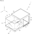
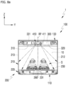
- the body 100 may form an upper surface and a rear surface of the accommodation space 10.
- the body 100 and the moving body 200 may form an overall appearance of the show case 1.
- An exterior of the show case 1 may be configured in the hexahedral form. That is, in the state in which the body 100 and the moving body 200 are coupled to each other and the accommodation space 10 is closed, the external appearance of the show case 1 may be configured in the hexahedral form.
- the show case 1 according to the embodiment of the present invention is not limited to such a shape, and may be configured in various three-dimensional shapes.
- the lower body 110 is positioned below the accommodation space 10.
- the lower body 110 may form a lowermost portion of the show case 1.
- the lower body 110 may form a bottom portion of the show case 1.
- the moving body 200 is configured to move forward and backward with respect to the body 100.
- the moving body 200 may include a base 220, a transparent window 210, and a turntable 230.
- the transparent window 210 may prevent a beam having a predetermined wavelength from being introduced into the accommodation space 10.
- the transparent window 210 may be configured to block ultraviolet rays.
- the ultraviolet rays as an electromagnetic wave in which a wavelength corresponds to 10 to 397 nm shorter than visible rays are light which has a strong chemical action and causes getting sunburn or discoloration.
- an ultraviolet-proof film may be attached to an inner surface or an outer surface of the transparent window 210.
- the inner surface or the outer surface of the transparent window 210 may be UV-coated with an ultraviolet-proof agent.
- the transparent window 210 includes a first window 211, a second window 212, and a third window 213.
- the first window 211 may form the front surface of the accommodation space 10.
- the second window 212 may form the left surface of the accommodation space 10.
- the third window 213 may form the right surface of the accommodation space 10.
- the show case 1 may be used as a device which may display the shoe S while keeping and caring the shoe S.
- the accommodation space 10 may be sealed from the outside air.
- the accommodation space 10 may be formed in the hexahedral form.
- the moving body 200 may be present at a first location and the show case 1 is in the closed state.
- the accommodation space 10 may be opened.
- an upper portion of the first window 211 is spaced to a front side in the first direction X from the front surface of the upper body 130 to form a gap (hereinafter, referred to as 'first gap').
- an upper portion of the first window 212 is spaced to a front side in the first direction X from the front surface of the upper body 120 to form a gap (hereinafter, referred to as 'first gap').
- the third window 213 is spaced to the front side in the first direction X from a right side surface of the middle body 120 to form a gap (hereinafter, referred to as 'third gap').
- the moving body 200 In the state in which the moving body 200 moves in the first direction X as much as possible, i.e., in the state in which the moving body 200 is positioned relatively at a frontmost side, the moving body 200 may be present at a second location and the show case 1 may be in the opened state.
- An internal panel 500 may be coupled to the inner surface of the middle body 120 or uncoupled from the inner surface of the middle body 120.
- the turntable 230 may form the upper surface on which the shoe S is placed.
- the upper surface of the turntable 230 may have a circular shape.
- the turntable 220 may form the lower surface of the accommodation space 10 jointly with the base 220.
- the turntable 230 may be rotatably coupled to the base 220 around a vertical axis, i.e., an axis parallel to a third direction Z.
- a motor 290 may be provided in the moving body 200.
- the motor 290 may be coupled to the base 220.
- the turntable 230 may rotate in conjunction with the rotation of the motor 290.
- Rotational force of the motor 290 may be delivered to the turntable 230 through a reducer.
- the motor 290 may rotate unidirectionally or reciprocally rotate bidirectionally.
- the turntable 230 is provided, and as a result, the shoe S may rotate in the accommodation space 10 or a display effect of the shoe S may be enhanced.
- the show case 1 may include an operating button 610 and a controller 600.
- the operating button 610 may be formed in the body 100.
- the operating button 610 may be formed on the front surface of the upper body 130.
- the turntable 230 may rotate or stop.
- the user manipulates the operating button 610 to adjust a rotational speed of the turntable 230.
- the user may input a rotation time of the turntable 230 into the controller 600 through the operating button 610.
- the user manipulates the operating button 610 to rotate the turntable 230 at a predetermined angle.
- the user may place the shoe S on the upper surface of the turntable 230 by holding any one part (heel top, lining, tong, etc.) of the shoe S. Thereafter, the user manipulates the operating button 610 to rotate the turntable 230 at a predetermined angle.
- the user manipulates the operating button 610 to rotate the turntable 230 at a predetermined angle so that a front and rear direction of the shoe S coincides with the first direction X.
- the user manipulates the operating button 610 to rotate the turntable 230 at a predetermined angle so that the front and rear direction of the shoe S form a predetermined angle with the first direction X.
- the shoe S may be placed (displaced) in a direction desired by the user.
- a sensor (not illustrated) that senses movement of the moving body 200 may be provided in the body 100.
- the controller 600 may rotate the turntable 230 by a signal of the sensor.
- a load sensor (not illustrated) may be provided in the base 220.
- the load sensor may automatically measure a load of the shoe S placed on the turntable 230.
- the rotational speed of the turntable 230 according to a measurement value of the load sensor may be set in the controller 600.
- the user may input the rotational speed of the turntable 230 according to the measurement value of the load sensor into the controller 600 through the operating button 610.
- a camera (not illustrated) may be provided in the show case 1.
- the camera may automatically shoot the shoe S placed on the turntable 230.
- the controller 600 may recognize the shape, size, and/or type of the shoe S through a shooting image of the camera.
- the rotational speed of the turntable 230 according to the shape, size, and/or type of the shoe S may be set in the controller 600.
- the user may input the rotational speed of the turntable 230 according to the shape, size, and/or type of the shoe S into the controller 600 through the operating button 610.
- the show case 1 may include an operating sensor.
- the operating sensor may sense an access of the user.
- the turntable 230 may be rotated or stopped by the sensing signal of the operating sensor.
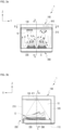
- FIG. 3a is a side view illustrating a use state of the show case 1 of FIG. 1b .
- FIG. 3a illustrates a state of illuminating the shoe S in the accommodation space 10.
- FIG. 3b is a front view illustrating the use state of the show case 1 of FIG. 1b .
- FIG. 3b illustrates an air flow in the accommodation space 10.
- the show case 1 may include a first illumination 410.
- the first illumination 410 may be provided in the upper body 130.
- the first illumination 410 may illuminate the accommodation space 10.
- the first illumination 410 may include a light source 411 and a lens 414.
- the light source 411 may intensively irradiate light onto the upper surface of the turntable 230 on which the shoe S is placed.
- the light of the light source 411 may intensively illuminate the shoe S placed on the upper surface of the turntable 230.
- an image of the shoe S stored in the accommodation space 10 may be changed by the light of the light source 411.
- the light of the light source 411 may illuminate the accommodation space 10 by passing through the lens 414.
- An ultraviolet-proof film may be attached to the lens 414 or the ultraviolet-proof agent may be coated on the lens 414 in order to block the ultraviolet rays.
- the light source 411 When the user manipulates the operating button 610, the light source 411 may be turned on or off. The user may input an operating time of the light source 411 into the controller 600 through the operating button 610. The user manipulates the operating button 610 to adjust the operating time of the light source 411.
- the controller 600 controls the current applied to the RGBW LEDs
- the aesthetics and a color sense of the shoe S stored in the accommodation space 10 may be variously changed.
- the user may input a pattern of the current applied to the RGBW LED into the controller 600 through the operating button 610.
- a hook may be formed at any one of the mounting bending portion 413b and the second insertion bending portion 412d.
- a portion to which the hook is hooked may be formed at the other one of the mounting bending portion 413b and the second insertion bending portion 412d. Therefore, as the mounting bending portion 413b is seated on the top of the first insertion bending portion 412c, a coupling force may be formed between the insertion housing 412 and the mounting housing 413.
- the closed projection portion 413c may extend downward on the lower end of the mounting sleeve 413a.
- the closed projection portion 413c may be formed around the vertical axis 231 in the circumferential direction.
- the lens 414 may be inserted into the inside of the insertion sleeve 412a.
- the lens 414 may be mounted on the top of the step portion 412e.
- the top of the step portion 412e may form a contact surface with the lens 414 in the circumferential direction.
- the lens 414 may be in close contact with the bottom of the closed projection portion 413c. Therefore, the lens 414 may close the circular hole 412b. Therefore, the gas flow of the upper space 130a and the accommodation space 10 through the circular hole 412b may be stopped.
- the light of the light source 411 may illuminate the accommodation space 10 by passing through the lens 414.
- An ultraviolet-proof film may be attached to the lens 414 or the ultraviolet-proof agent may be coated on the lens 414 in order to block the ultraviolet rays.
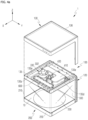
- the body 100 may include the middle body 120.
- the middle body 120 may form the rear surface of the accommodation space 10.
- the internal panel 500 may be coupled to the front surface of the middle body 120 in the accommodation space 10. Therefore, the turntable 500 may form the rear surface of the accommodation space 10 jointly with the middle body 120.
- the internal panel 500 may be detachably coupled to the middle body 120.
- the internal panel 500 may be coupled to the front surface of the middle body 120 by a magnetic force.
- the front surface of the middle body 120 may generally form the plane.
- the internal panel 500 may have the thin plate shape.
- the rear surface of the internal panel 500 may be in close contact with the front surface of the middle body 120.
- the front surface and/or the rear surface of the internal panel 500 may form a similar shape and a similar area to the front surface of the middle body 120.
- the hexahedral shape and size of the accommodation space 10 may be maintained substantially constantly. Therefore, even though the internal panel 500 is coupled or not coupled to the middle body 120, the accommodation space 10 may show predetermined aesthetics based on the shape and the size.
- the front surface of the internal panel 500 may be made of the same or similar material as the front surface of the middle body 120.
- the light of the first illumination 410 and the second illumination 420 reflected on the rear surface of the accommodation space 10 may be delivered to a vision of a person who sees the shoe S to be the same or similar. Therefore, even though the internal panel 500 is coupled or not coupled to the middle body 120, the accommodation space 10 may show predetermined aesthetics based on the light.
- the internal panel 500 may be configured to accommodate an image sheet 550.
- the image sheet 500 may mean a sheet including an image to the letter.
- the image sheet 550 may be a sheet printed with a photo, a picture, or a letter.
- the internal panel 500 may form an insertion space 500c accommodating the image sheet 550.
- the internal panel 500 may include a transparent or translucent material so as to expose the image sheet 550 to the accommodation space 10.
- the image sheet 550 may be exposed to the vision of the person who sees the shoe S accommodated in the show case 1. Therefore, the user of the show case 1 may display the photo and the picture on the rear surface of the accommodation space 10.
- the insertion space 500c may be opened to the upper side.
- the image sheet 550 may be inserted into the insertion space 500c through an upper opening.
- the image sheet 550 inserted into the insertion space 500c may be withdrawn to the outside through the upper opening. Therefore, the user of the show case 1 may display various photos and pictures on the rear surface of the accommodation space 10.
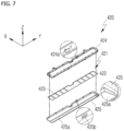
- FIG. 7 is an exploded perspective view of the second illumination 420 of the show case 1 of FIG. 4b .
- the second illumination 420 may illuminate the rear surface of the accommodation space 10.
- the second illumination 420 may be parallel to the first direction X which is the horizontal direction and form the symmetry based on the reference surface RP which is the vertical surface.
- the extension line of the vertical axis 231 may be positioned within the reference plane RP.
- the second illumination 420 may include a light source module 421, a heat dissipation cover 424, and a transmission cover 425.
- the light source module 421 may be formed to be long in the second direction Y.
- the light source module 421 may be formed by an LED module.
- the light source module 421 may include a module substrate 422 and a plurality of white LEDs.
- a power supply (not illustrated) may be provided in the base 220.
- the power supply may supply power to the light source module 421.
- the controller 600 may control the power supplied to the light source module 421 from the power supply.
- the module substrate 422 may be formed to be long in the second direction Y.
- the plurality of LEDs may be placed on the bottom of the module substrate 422 at a predetermined gap in the second direction Y. Therefore, light which the light source module 421 irradiates onto the rear surface of the accommodation space 10 may form a substantially constant illuminance in the second direction Y.
- the visibility of the rear surface of the accommodation space 10 is enhanced, and as a result, the display effect of the image sheet 550 accommodated in the internal panel 500 may be enhanced.
- the display effect of the image sheet 550 accommodated in the internal panel 500 may be enhanced.
- the light source module 421 may be configured to change the color of the light.
- the light source module 421 may be constituted by the module substrate 422 and a plurality of Red Green Blue White (RGBW) LEDs.
- the controller 600 may control current applied to a Red (R) LED, a Green (G) LED, a Blue (B) LED, and a White (W) LED.
- the controller 600 controls the current applied to the RGBW LEDs
- the aesthetics and the color sense of the rear surface of the accommodation space 10 may be variously changed.
- the user may input a pattern of the current applied to the RGBW LED 423 into the controller 600 through the operating button 610.
- a measurement sensor 138 measuring the temperature and/or the humidity may be installed at one side of the accommodation space 10.
- the measurement sensor 138 may be installed in the upper body 130, the middle body 120, or the base 220.
- the measurement sensor 138 may be installed on the upper bottom plate 135a.
- the controller 600 may receive a measurement value of the measurement sensor 138.
- the controller 600 may control the current applied to the RGBW LED 423 according to the measurement value of the measurement sensor 138.
- the wavelength of the light emitted by the second illumination 420 may vary depending on the measurement value of the measurement sensor 138. Therefore, a color stimulus of the light reflected on the rear surface of the accommodation space 10 may vary depending on the measurement value of the measurement sensor 138.
- the color stimulus is a term that means a stimulus which reflected light of a colored object gives to the color sense of the eye.
- the color sense of the eye When the eye of the person is stimulated by the light, there are three color senses of sensing red, green, and blue, and the color may be displayed by a stimulus amount (triple stimulus value) for three color senses.
- a current amount applied to the RGBW LED 423 may be set in the controller 600 according to the measurement value of the measurement sensor 138.
- the user may input the current amount applied to the RGBW LED 423 according to the measurement value of the measurement sensor 138 into the controller 600 through the operating button 610.
- the appropriate temperature range may mean a temperature range suitable for keeping the shoe S.
- the controller 600 may change the current amount applied to the RGBW LED 423 according to the measurement value of the measurement sensor 138 being within the appropriate temperature range.
- the controller 600 may apply the current to the RGBW LED 423 so that the second illumination 420 emits green or blue light.
- the controller 600 may apply the current to the RGBW LED 423 so that the second illumination 420 emits red light.
- the controller 600 may apply the current to the RGBW LED 423 so that the second illumination 420 continuously flashes light of a specific color.
- the appropriate humidity range may mean a humidity range suitable for keeping the shoe S.
- the controller 600 may change the current amount applied to the RGBW LED 423 according to the measurement value of the measurement sensor 138 being within the appropriate humidity range.
- the controller 600 may apply the current to the RGBW LED 423 so that the second illumination 420 emits the green or blue light.
- the controller 600 may apply the current to the RGBW LED 423 so that the second illumination 420 emits the red light.
- the controller 600 may apply the current to the RGBW LED 423 so that the second illumination 420 continuously flashes light of a specific color.
- the heat dissipation cover 424 and the transmission cover 425 may be formed to be long in the second direction Y.
- the light source module 421 may be connected to the heat dissipation cover 424.
- the heat dissipation cover 424 may form the opening at the lower side thereof.
- the transmission cover 425 may be coupled to at the heat dissipation cover 424 so as to seal the opening of the heat dissipation cover 424.
- a hook 424a may be formed in any one of the heat dissipation cover 424 and the transmission cover 425.
- a holing hole 425b to which the hook 424a is hooked may be formed in any one of the heat dissipation cover 424 and the transmission cover 425.
- the hook 424a may be hooked to the hooking hole 425b. Therefore, the coupling force may be formed between the heat dissipation cover 424 and the transmission cover 425.
- the heat dissipation cover 424 and the transmission cover 425 may form a space (hereinafter, referred to as 'light source space') accommodating the light source module 421 jointly.
- the light source space may be formed to be long in the second direction Y.
- the top of the module substrate 422 may be coupled to the heat dissipation cover 424 above the light source space. Thermal energy of the light source module 421 may be delivered to the heat dissipation cover 424. The heat dissipation cover 424 may discharge heat of the light source module 421 to the upper space 130a.
- the heat dissipation cover 424 may be made of a metallic material having high thermal conductance.
- the LED 423 may be provided on the bottom of the module substrate 422.
- the transmission cover 425 may include a transmission portion 425a that penetrates light of the light source module 421.
- the transmission portion 425a may be formed to be long in the second direction Y.
- the transmission cover 425 may be made of a transparent glass or resin material.
- the front surface of the transmission cover 425 except for the transmission portion 425a may be coated with an opaque material.
- a hole (hereinafter, referred to as 'rear surface hole') into which the transmission portion 425a is inserted may be formed on the upper bottom plate 135a.
- the rear surface hole may be formed to be long in the second direction Y.
- the transmission portion 425a may be inserted into the rear surface hole.
- the outer surface of the transmission portion 425a may be in close contact with the inner surface of the rear surface hole. Therefore, the gas flow of the upper space 130a and the accommodation space 10 through the transmission cover 425 and the inner surface of the rear surface hole may be stopped.
- FIG. 8a is a cross-sectional view of the show case 1 of FIG. 3b taken along line C-C.
- FIG. 8b is a cross-sectional view of the show case 1 of FIG. 3a taken along line A-A.
- the alternate long and short dash line illustrated in FIG. 8b may mean the extension line of the vertical axis 231.
- the accommodation space 10 may be parallel to the first direction X which is the horizontal direction and form the symmetry based on the reference surface RP which is the vertical surface.
- the extension line of the vertical axis 231 may be positioned within the reference plane RP.
- the light source 411 may be provided on the extension line of the vertical axis 231.
- the first illumination 410 may irradiate light to the top of the turntable 230 on which the shoe S is placed on the extension line of the vertical axis 231.
- An alternate long and short dash line arrow illustrated in FIGS. 8a and 8b may mean the extension line of the first reflection surface 413d.
- An alternate long and two short dashes line arrow illustrated in FIGS. 8a and 8b may mean the extension line of the second reflection surface 412f.
- the user may place the shoe S on the top of the turntable 230 by holding any one part (heel top, lining, tong, etc.) of the shoe S.
- the user manipulates the operating button 610 to rotate the turntable 230 at a predetermined angle so that the front and rear direction of the shoe S coincides with the first direction X.
- the user manipulates the operating button 610 to rotate the turntable 230 at a predetermined angle so that the front and rear direction of the shoe S form a predetermined angle with the first direction X.
- the user manipulates the operating button 610 to continuously rotate the turntable 230.
- a beam angle of the first illumination 410 may form the axial symmetry around the vertical axis 231. Therefore, the light emitted by the first illumination 410 may form the same illuminance around the vertical axis 231 in the circumferential direction.
- the transparent window 210 may form the front surface, and both side surfaces (the left surface and the right surface) of the accommodation space 10.
- the transparent window 210 may include the first window 211, the second window 212, and the third window 213.
- the first window 211 may form the front surface of the accommodation space 10.
- the second window 212 may form the left surface of the accommodation space 10.
- the third window 213 may form the right surface of the accommodation space 10.
- the user may observe the shoe S accommodated in the accommodation space 10 at the front side, the left side, and the right side. Further, the user may observe the shoe S accommodated in the accommodation space 10 between front side and the left side and between the front side and the right side of the accommodation space 10.
- the beam angle of the first illumination 410 forms the axial symmetry around the vertical axis 231, and as a result, the light reflected on the surface of the shoe S may maintain the same color stimulus regardless of the location of the user based on the accommodation space 10. Therefore, the aesthetics and the color sense of the shoe S stored in the accommodation space 10 may be maintained to be the same.
- a space between the extension line of the vertical axis 231 and the extension line of the first reflection surface 413d will be referred to as 'first space'.
- a space between the extension line of the first reflection surface 413d and the extension line of the second reflection surface 412f will be referred to as 'second space'.
- the first reflection surface 413d may be provided next to the light source 411 around the extension line of the vertical axis 231.
- the second reflection surface 412f may be provided below the first reflection surface 413d.
- the first reflection surface 413d and the second reflection surface 412f may form a surface reflecting the light of the light source 411 toward the accommodation space 10.
- the light of the first illumination 410 forms a lower illuminance in the second space than the first space, a part of the shoe S positioned in the second space may be illuminated. Therefore, even though a part of the shoe S is positioned outside the first space, the first illumination 410 may wholly illuminate the shoe S placed on the top of the turntable 230.
- the light reflected on the surface of the shoe S may generally maintain the same color stimulus. Therefore, the aesthetics and the color sense of the shoe S stored in the accommodation space 10 may be generally maintained to be the same.
- the dotted line illustrated in FIG. 8b may mean the progress of the light of the second illumination 420 penetrating a transmission surface.
- a dotted-line arrow illustrated in the enlarged diagram of FIG. 8b may mean a normal direction of the transmission surface.
- the transmission portion 425a may reflect the light of the light source module 421 having a larger incident angle. Therefore, the light of the light source module 421 which penetrates the transmission portion 425a may form a high illuminance around the normal direction of the bottom of the transmission portion 425a.
- the normal direction of the bottom of the transmission portion 425a, which contacts the accommodation space 10 may face the front surface of the internal panel 500.
- the top of the transmission portion 425a may form a surface parallel to the bottom. Therefore, the second illumination 420 may intensively illuminate the rear surface of the accommodation space 10.
- the visibility of the rear surface of the accommodation space 10 is enhanced, and as a result, the display effect of the image sheet 550 accommodated in the internal panel 500 may be enhanced.
- the display effect of the image sheet 550 accommodated in the internal panel 500 may be enhanced.
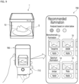
- FIG. 9 is a drawing illustrating an example of the state in which a shoe image is input and second illumination 420 is recommended in a show case 1 according to an embodiment of the present disclosure.
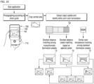
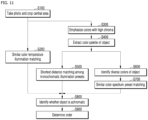
- FIG. 10 and FIG. 11 are drawings illustrating an example of a process in which second illumination 420 is recommended in a show case 1 according to an embodiment of the present disclosure.
- FIG. 12 is a drawing illustrating an example of processing according to an area on the CIE LAB color coordinates when recommending second illumination 420 in a show case 1 according to an embodiment of the present disclosure.
- FIG. 13 is a drawing illustrating an example of a type of second illumination 420 recommended to a user in a show case 1 according to an embodiment of the present disclosure.
- FIG. 9 to FIG. 13 An algorithm for recommending the most suitable illumination to the user on the basis of shoes accommodated in the accommodation space 10 in a show case 1 according to an embodiment of the present disclosure will be described with reference to FIG. 9 to FIG. 13 . In this case, the description will be made with reference to above-described FIG. 1 to FIG. 8b as well.
- the show case 1 may include a body 100, a moving body 200, a blowing part 330, a first illumination 410, a second illumination 420, an input part 710, and a controller 600.
- the body 100 is a part that forms part of an accommodation space 10, and may form a reference position for the moving body 200 that is moved to open and close the accommodation space 10.
- the moving body 200 is a part that forms the accommodation space 10 together with the body 100 and includes a transparent window 210. That is, the moving body 200 is a part that forms the remaining part of the accommodation space 10, and the moving body 200 may move relative to the body 100 to open and close the accommodation space 10.
- the moving body 200 may be configured to reciprocate relative to the body 100 between a first position and a second position in the forward and backward directions.
- the state in which the moving body 200 is at the first position may be defined as a closed state
- the state in which the moving body 200 is at the second position may be defined as an open state.
- the accommodation space 10 may be sealed from the outside air. Therefore, when the accommodation space 10 is closed after the shoes are accommodated in the accommodation space 10, the shoes may be prevented from being exposed to the dust and moisture of the outside air.
- the blowing part 330 is configured to circulate the air in the accommodation space 10, and may control the air condition (particularly, humidity) of the accommodation space 10 such that the shoes accommodated in the accommodation space 10 are placed in an appropriate environment.
- a suction port 310 and a discharge port 320 may be formed in a part of the accommodation space 10, respectively.
- the air of the accommodation space 10 may be sucked into the air flow path 300 through the suction port 310 by the blowing part 330, and the air of the air flow path 300 may be discharged back to the accommodation space 10 through the discharge port 320 by the same. Therefore, the air forcibly blown by the blowing part 330 may circulate through the accommodation space 10 and the air flow path 300.
- the show case 1 accommodates the shoes in the accommodation space 10 formed by the body 100 and the moving body 200, switches to the closed state, and displays the shoes while controlling the state of the accommodation space 10 by circulating the air of the accommodation space 10 through the blowing part 330, the shoe display effect and the shoe management effect may be effectively implemented at the same time.
- the first illumination 410 is a part that illuminates the shoes placed on the bottom of the accommodation space 10, and may intensively illuminate the shoes S placed on the upper surface of the turntable 230, thereby improving the display effect of shoes S.
- the second illumination 420 is a part that illuminates the rear surface of the accommodation space 10, and may improve the visibility of the rear surface of the accommodation space 10 and provide a visual effect as a background for shoes.
- the second illumination 420 is configured to change the color of light, so that the aesthetics and colors of the rear surface of the accommodation space 10 may be varied.
- the first illumination 410 may intensively illuminate the area where shoes are placed, and the second illumination 420 may illuminate the rear surface of the accommodation space 10, thereby maximizing the display effect of shoes and improving the interior effect of the space where the shoes are accommodated.
- the color of the light from the second illumination 420 may vary to change the aesthetics and colors of the rear surface of the accommodation space 10, it may be desirable to adjust the second illumination 420 such that it reflects the characteristics of the shoes accommodated.
- the show case 1 may recommend the type of second illumination 420 that matches the accommodated shoes well to guide the user to select one of them.
- the input part 710 is a part to which an image of the shoe accommodated in the accommodation space 10 is input, and an image of the shoe may be input as basis data for analyzing the type of the second illumination 420 that matches the accommodated shoes well.
- the controller 600 may recommend the type of second illumination 420 to the user on the basis of the image of shoe input to the input part 710. That is, the controller 600 may analyze the type of second illumination 420 that matches the accommodated shoes well on the basis of the input image of shoe as the basis data and then recommend the same to the user.
- the controller 600 may recommend the second illumination 420 that matches the image of shoe well, which is input to the input part 710, to the user, thereby enabling the user to more easily select the type of second illumination 420 and improving the aesthetic sense through the second illumination 420 that reflects the characteristics of each shoe.
- the show case 1 may further include a portable device 700 equipped with an input part 710 and capable of remote communication with the controller 600.
- the image of shoe may be captured by the portable device 700 and input to the input part 710, and the type of second illumination 420 recommended to the user by the controller 600 may be displayed through the portable device 700.
- an image of the shoe accommodated in the show case 1 may be captured by the input part 710 provided in the portable device 700 while the user is carrying the portable device 700 separately configured from the show case 1.
- controller 600 may analyze the type of second illumination 420 that matches the accommodated shoe well on the basis of the image captured by the portable device 700, and, as illustrated in FIG. 9 , display the type of second illumination 420 to be recommended through the portable device 700.
- the image of shoe is input through the portable device 700, and since the type of second illumination 420 to be recommended is displayed through the portable device 700 according thereto, it may be more convenient to input the image of shoe and identify the type of second illumination 420 to be recommended.
- the portable device 700 may display a reference line 720 corresponding to the outer lines of the body 100 and the moving body 200 when capturing the image of shoe.
- a reference line 720 corresponding to the outer shape of the show case 1 may be displayed on the screen of the portable device 700.
- the user may align the actual shape of the actual show case 1 to the reference line 720 of the portable device 700 and then capture the same. Through this, it is possible to induce the image of shoe to always be captured with a specific composition and a specific size when capturing the image using the portable device 700.
- the image of shoe to be captured may vary depending on the capturing time or the surrounding environment. Therefore, there is a concern that the second illumination 420 is to be recommended according to the influences of the capturing time or the surrounding environment, instead of reflecting the unique characteristics of the shoes.
- the image of shoe input through the input part 710 may be captured through the portable device 700 and then a dummy area Ad may be removed therefrom (S100).
- a dummy area Ad which is not related to the shoe, may be produced depending on the size of the accommodated shoe or the like.
- this dummy area Ad is not related to the basis data for analyzing the type of second illumination 420 that matches the accommodated shoes well, it may be desirable to analyze the type of second illumination 420 after excluding the same.
- the accommodation space 10 may be divided into a plurality of horizontal sections and a plurality of vertical sections, and the sections other than a specific section may be regarded as dummy areas Ad.
- the dummy areas Ad may be removed using a computer vision technology including YOLOv5 or a technology for segmenting the area of an object in a photographed image.
- the dummy areas Ad may be removed using various technologies and methods as needed, such as having the user directly cut out the dummy areas Ad from the captured shoe image on the portable device 700.
- the dummy areas Ad are removed when capturing the image of shoe using the portable device 700, a portion of the image, which does not need to be reflected when recommending the second illumination 420, may be excluded, so that the recommendation of the second illumination 420 may be performed more effectively.
- the image of shoe from which the dummy areas Ad are removed may be subjected to white balance such that the characteristics of the shoes may be reflected more accurately as the basis data.
- the second illumination 420 may be configured to change to any one of a plurality of preset illuminations that are set in advance.
- the controller 600 may recommend at least one of similar color temperature illumination Lk, similar monochromatic illumination Lc, and similar spectrum illumination Ls for the image of shoe, among the preset illuminations, to the user (S200, S500, and S700).
- the similar color temperature illumination Lk may be preset illumination having the color temperature most similar to the image of shoe.
- the similar monochromatic illumination Lc may be preset illumination having the color most similar to the image of shoe.
- the similar spectrum illumination Ls may be illumination in a spectrum state having the color most similar to the image of shoe.
- the show case 1 since the show case 1 according to the present embodiment recommends at least one of the similar color temperature illumination Lk, the similar monochromatic illumination Lc, and the similar spectrum illumination Ls among the preset illuminations set in advance to the user, it is possible to make recommendations reflecting the accommodated shoes in various ways, thereby increasing the user's utilization of the second illumination 420.
- the similar color temperature illumination Lk may be preset illumination to be recommended according to the average color temperature of pixels whose brightness (value) is within the upper setting range in the image of shoe.
- the brightest pixel may be extracted separately from the captured image of shoe and analyzed to analyze which color temperature of preset illumination matches the same from among the preset illuminations imitating a standard light source.
- the values of the pixels of the shoe image may be converted into HSV units so that pixels whose brightness is within the upper setting range (for example, the upper 10%) may be separately extracted. Then, the average color temperature of the extracted pixels may be calculated to recommend the closest preset illumination as the similar color temperature illumination Lk.
- the second illumination 420 having the most similar color temperature to the image of shoe may be recommended.
- the similar monochromatic illumination Lc may be preset illumination to be recommended according to the color with the highest proportion in the color palette Cp that reflects pixels with relatively high chroma in the image of shoe.
- the color palette Cp indicates the result in which the primary colors constituting the image of shoe are derived into a plurality of clusters, as illustrated in FIG. 10 .
- the color with high chroma may be emphasized and analyzed in the captured image of shoe to analyze which color of preset illumination matches the shoe well, among the preset illuminations.
- the second illumination 420 may be recommended to reflect the tendency to place more weight on colors with higher chroma than on actual colors when recognizing objects.
- the color palette Cp may be obtained by amplifying the number of pixels in the image of shoe whose value ((a*)2+(b*)2)1/2 is greater than or equal to a first setting value on the three-dimensional coordinates defined by L*, a*, and b*, which are color spaces for color recognition (S300), and then deriving a plurality of clusters therefrom using a clustering algorithm (S400).
- the three-dimensional coordinates defined by L*, a*, and b* which are color spaces for color recognition, may be the LAB color coordinates of the International Commission on Illumination (CIE).
- L* represents brightness information and indicates 0 (black) to 100 (white).
- a* represents minus a (green) to plus a (red).
- b* represents minus b (blue) to plus b (yellow).
- the values of the pixels of the shoe image may be converted to Lab units, and the number of pixels whose value ((a*)2+(b*)2)1/2 is greater than or equal to the first setting value (e.g., 35) may be amplified (e.g., increased by 30 times).
- a color palette Cp including a plurality of (e.g., 12) clusters may be derived from the color values of the respective pixels calculated above using a clustering algorithm.
- K-means clustering Fuzzy C-means, etc.
- Fuzzy C-means Fuzzy C-means, etc.
- present disclosure is not necessarily limited thereto, and various technologies and methods may be utilized as needed.
- the second illumination 420 may be recommended by utilizing an analysis that emphasizes the color with higher chroma.
- the controller 600 may recommend the similar monochromatic illumination Lc in the order of the shortest Euclidean distance from the color with the highest proportion in the color palette Cp derived as a plurality of clusters.
- the Euclidean distance is obtained by representing two points as coordinates, adding the squares of the differences of corresponding components, and then calculating the square root thereof.
- the color with the highest proportion may be set as a dominant color in the color palette Cp derived as described above, and the Euclidean distance between the Lab value of the dominant color and the Lab value of the preset illumination may be calculated, so that the similar monochromatic illumination Lc may be recommended in ascending order from the shortest distance.
- the recommendation order of the second illumination 420 may be determined in a similar order to the color of the shoe.
- the similar spectrum illumination Ls may be preset illumination in a spectrum state to be recommended in the order of the shortest Euclidean distance from the color with the highest proportion in the color palette Cp.
- the spectrum state indicates the state in which colors are distributed and arranged in the order of wavelengths, as illustrated in FIG. 10 .
- Another method of selecting the type of second illumination 420 that matches the accommodated shoes well is to analyze which color of preset illumination matches well, among the preset illumination, and to recommend such a color in a spectrum state rather than a monochromatic state.
- a method of recommending the most similar color based on the primary colors constituting the image of shoe as similar spectrum illumination Ls in the spectrum state may also be importantly considered.
- the recommendation order of the second illumination 420 in the spectrum state may be determined in a similar order to the color of the shoe.
- the colors included in the image of shoe may be considered diverse (S600).
- the second illumination 420 that reflects the characteristics of the accommodated shoes
- a color in a single color or spectrum state may be recommended on the basis of the primary colors as described above, if the image of shoe is configured in various colors, instead of a color in a specific family, it may also be an important consideration.
- the Euclidean distances between the respective colors may be calculated through values a* and b* of three colors with the highest distribution in the color palette Cp extracted as described above.
- the maximum value of the calculated distances is greater than the second setting value (e.g., 35)
- the shoe may be regarded as having various colors rather than a color in a specific family.
- the maximum value of the calculated distances is greater than the second setting value (e.g., 35)
- the second setting value e.g. 35
- the show case 1 determines whether or not the shoe image has diverse colors through the Euclidean distances between three colors with relatively high distribution in the color palette Cp derived as a plurality of clusters
- the second illumination 420 may be recommended by utilizing an analysis reflecting the case where the shoe has various colors.
- the controller 600 may preferentially recommend the rainbow-typed similar spectrum illumination Ls if the colors included in the image of shoe are considered diverse or if the absolute values of a* and b* of the color with the highest proportion in the color palette Cp are both smaller than a third setting value.
- the rainbow type indicates the type in which the similar spectrum illumination Ls is configured as a plurality of colors between red and purple, which are dispersed and arranged by the dispersion of visible light, instead of as a color in a specific family.
- the accommodated shoes are configured in various colors, it may be desirable to recommend the rainbow-typed similar spectrum illumination Ls, instead of recommending a color in a specific family close to the primary color.
- the property of the primary color does not belong to a specific color family and is not distinct, so in this case as well, it may be desirable to recommend the rainbow-typed similar spectrum illumination Ls, instead of recommending a color in a specific family.
- the shoe image has various colors or if the property of the color with the highest proportion in the color palette Cp derived as a plurality of clusters is not distinct, the rainbow-typed similar spectrum illumination Ls is preferentially recommended, so the second illumination 420 may be recommended to reflect the case where there is no bias toward a specific color.
- the shoe image may be regarded as achromatic (S800).
- the primary color may be converted to a Lab value to calculate the value of ((a*)2+(b*)2)1/2 of the corresponding color.
- the pixels whose calculated values are higher than the first setting value (e.g., 35) are relatively dark colors, they may be amplified more than other pixels. Therefore, such colors may be likely to be output as primary colors when extracting the color palette Cp. Nevertheless, if the value of ((a*)2+(b*)2)1/2 of the primary color is lower than the fourth setting value (e.g., 35), the corresponding image of shoe may be regarded as achromatic.
- the show case 1 determines whether or not the image of shoe is achromatic through the property of the color with the highest proportion in the color palette Cp derived as a plurality of clusters
- the second illumination 420 may be recommended by utilizing an analysis reflecting the case where the shoe is achromatic.
- the controller 600 may preferentially recommend similar color temperature illumination Lk over similar monochromatic illumination Lc if the image of shoe is considered to be achromatic (S900).
- the second illumination 420 reflecting colors may not go well with it, so it may be preferable to preferentially recommend similar color temperature illumination Lk over similar monochromatic illumination Lc.
- the second illumination 420 may be recommended by presenting similar monochromatic illumination Lc closest to the primary color and then presenting similar color temperature illumination Lk.
- the similar color temperature illumination Lk is preferentially recommended over the similar monochromatic illumination Lc when the image of shoe is achromatic, it is possible to induce the selection of second illumination 420 with the closest color temperature to the shoe image, instead of matching the color of the shoe image.
- the controller 600 may recommend similar spectrum illumination Ls, regardless of the priority between the similar monochromatic illumination Lc and the similar color temperature illumination Lk.
- one of the similar color temperature illumination Lk and the similar monochromatic illumination Lc may be preferentially recommended.
- the second illumination 420 may be recommended by presenting the similar spectrum illumination Ls separately from the similar monochromatic illumination Lc and the similar color temperature illumination Lk.
- the show case 1 since the show case 1 according to the present embodiment recommends the similar spectrum illumination Ls independently of the priority between the similar monochromatic illumination Lc and the similar color temperature illumination Lk to be recommended, it is possible to provide more diverse choices to the user who wishes to select the type of second illumination 420.
- the similar color temperature illumination Lk is recommended first, and then the similar monochromatic illumination Lc may be sequentially recommended.
- the similar spectrum illumination Ls may be sequentially recommended, regardless of the above.
- the similar monochromatic illumination Lc closest to the primary color may be recommended first, and then the similar color temperature illumination Lk and the remaining similar monochromatic illumination Lc may be sequentially recommended.
- the similar spectrum illumination Ls may be sequentially recommended, regardless of the above.
- the similar color temperature illumination Lk may be recommended first, and then the similar monochromatic illumination Lc may be sequentially recommended.
- the similar spectrum illumination Ls is sequentially recommended, regardless of the above, such that the rainbow-typed similar spectrum illumination Ls is preferentially recommended.
- second illumination 420 to be recommended has been described above, the present disclosure is not necessarily limited to those shown in FIG. 13 , and various combinations of second illuminations 420 may be recommended depending on the characteristics of the accommodated shoes and the user's preference.
- the show case is configured to accommodate an object in the accommodation space formed by the body and the moving body and then switch to a closed state to display the object, and at the same time, configured to circulate the air in the accommodation space through the blowing part to control the state of the accommodation space, both the object display effect and the object management effect may be effectively implemented.
- the first illumination intensively illuminates the area where the object is placed and since the second illumination illuminates the rear surface of the accommodation space, it is possible to improve the interior effect of the space where the object is accommodated while maximizing the display effect of the object.
- the controller since the controller recommends the second illumination that best matches the object image input to the input part to the user, the user may select the type of second illumination more easily and the aesthetic sense may be improved through the second illumination that reflects the characteristics of each object.
- the object image is input through the portable device and since the type of second illumination to be recommended is displayed through the portable device according thereto, it may be more convenient to input the object image and identify the type of second illumination to be recommended.
- the reference line is displayed when capturing the object image through the portable device, even if the photographers differ, the image may always be captured to have a similar composition, enabling more accurate input of the image for recommending the second illumination.
- a portion of the image, which does not need to be reflected when recommending the second illumination may be excluded, so that the recommendation of the second illumination may be performed more effectively.
- recommendation may be performed to reflect the accommodated object in various ways, thereby increasing the user's utilization of the second illumination.
- the second illumination having the most similar color temperature to the object image may be recommended.
- the similar monochromatic illumination that goes well with pixels with relatively high chroma in the object image is recommended, it is possible to recommend the second illumination reflecting the tendency to place more weight on colors with higher chroma than on actual colors when recognizing an object.
- the second illumination may be recommended by utilizing an analysis that emphasizes the color with higher chroma.
- the recommendation order of the second illumination may be determined in a similar order to the color of the object.
- the recommendation order of the second illumination in the spectrum state may be determined in a similar order to the color of the object.
- the show case since the show case is configured to determine whether or not the object image has diverse colors through the Euclidean distances between three colors with relatively high distribution in the color palette derived as a plurality of clusters, the second illumination may be recommended by utilizing an analysis reflecting the case where the object has various colors.
- the rainbow-typed similar spectrum illumination is preferentially recommended, so the second illumination may be recommended to reflect the case where there is no bias toward a specific color.
- the show case since the show case is configured to determine whether or not the object image is achromatic through the property of the color with the highest proportion in the color palette derived as a plurality of clusters, the second illumination may be recommended by utilizing an analysis reflecting the case where the object is achromatic.
- the similar color temperature illumination is preferentially recommended over the similar monochromatic illumination when the object image is achromatic, it is possible to induce the selection of second illumination with the closest color temperature to the object image, instead of matching the color of the object image.
- the similar spectrum illumination is recommended independently of the priority between the similar monochromatic illumination and the similar color temperature illumination to be recommended, it is possible to provide more diverse choices to the user who wishes to select the type of second illumination.
Landscapes
- Engineering & Computer Science (AREA)
- General Engineering & Computer Science (AREA)
- Multimedia (AREA)
- Signal Processing (AREA)
- Footwear And Its Accessory, Manufacturing Method And Apparatuses (AREA)
- Freezers Or Refrigerated Showcases (AREA)
- Arrangement Of Elements, Cooling, Sealing, Or The Like Of Lighting Devices (AREA)
- Illuminated Signs And Luminous Advertising (AREA)
Applications Claiming Priority (2)
| Application Number | Priority Date | Filing Date | Title |
|---|---|---|---|
| KR1020220156661A KR20240074511A (ko) | 2022-11-21 | 2022-11-21 | 전시장치 |
| PCT/KR2023/014281 WO2024111842A1 (ko) | 2022-11-21 | 2023-09-20 | 전시장치 |
Publications (2)
| Publication Number | Publication Date |
|---|---|
| EP4512282A1 true EP4512282A1 (de) | 2025-02-26 |
| EP4512282A4 EP4512282A4 (de) | 2025-09-24 |
Family
ID=91195741
Family Applications (1)
| Application Number | Title | Priority Date | Filing Date |
|---|---|---|---|
| EP23894773.3A Pending EP4512282A4 (de) | 2022-11-21 | 2023-09-20 | Messegerät |
Country Status (5)
| Country | Link |
|---|---|
| US (1) | US12419442B2 (de) |
| EP (1) | EP4512282A4 (de) |
| KR (1) | KR20240074511A (de) |
| CN (1) | CN119156157A (de) |
| WO (1) | WO2024111842A1 (de) |
Families Citing this family (1)
| Publication number | Priority date | Publication date | Assignee | Title |
|---|---|---|---|---|
| CN120122380A (zh) * | 2025-04-15 | 2025-06-10 | 杭州奥创商业展具有限公司 | 一种led交互式智控灯箱 |
Family Cites Families (8)
| Publication number | Priority date | Publication date | Assignee | Title |
|---|---|---|---|---|
| KR100298786B1 (ko) | 1998-07-27 | 2001-10-27 | 주영한 | 위생처리용신발장 |
| RU2565582C2 (ru) * | 2009-06-05 | 2015-10-20 | Конинклейке Филипс Электроникс Н.В. | Устройство управления освещением |
| US20130002098A1 (en) * | 2011-06-30 | 2013-01-03 | Pepsico, Inc. | Modular Refrigerated Merchandise Display System |
| KR20130034367A (ko) * | 2011-09-28 | 2013-04-05 | 조홍래 | 투명 디스플레이를 갖는 쇼케이스 |
| US9089227B2 (en) | 2012-05-01 | 2015-07-28 | Hussmann Corporation | Portable device and method for product lighting control, product display lighting method and system, method for controlling product lighting, and -method for setting product display location lighting |
| KR20140032725A (ko) | 2012-09-07 | 2014-03-17 | 김정익 | 디스플레이 이미지 컬러 매칭형 쇼케이스 |
| US20180127150A1 (en) * | 2016-10-31 | 2018-05-10 | Berk B. ADANUR | Modular storage container |
| KR102080373B1 (ko) | 2017-08-21 | 2020-03-04 | 김태욱 | 쇼케이스 및 그 구동 방법 |
-
2022
- 2022-11-21 KR KR1020220156661A patent/KR20240074511A/ko active Pending
-
2023
- 2023-09-20 EP EP23894773.3A patent/EP4512282A4/de active Pending
- 2023-09-20 CN CN202380035678.0A patent/CN119156157A/zh active Pending
- 2023-09-20 WO PCT/KR2023/014281 patent/WO2024111842A1/ko not_active Ceased
- 2023-09-20 US US18/833,436 patent/US12419442B2/en active Active
Also Published As
| Publication number | Publication date |
|---|---|
| US12419442B2 (en) | 2025-09-23 |
| US20250151928A1 (en) | 2025-05-15 |
| KR20240074511A (ko) | 2024-05-28 |
| WO2024111842A1 (ko) | 2024-05-30 |
| EP4512282A4 (de) | 2025-09-24 |
| CN119156157A (zh) | 2024-12-17 |
Similar Documents
| Publication | Publication Date | Title |
|---|---|---|
| US11748912B2 (en) | Hyperspectral imaging spectrophotometer and system | |
| US9357613B2 (en) | Display and lighting arrangement for a fitting room | |
| EP3965611B1 (de) | Intelligentes spiegelsystem und verfahren zur verwendung davon | |
| CN201837891U (zh) | 具有环境依赖颜色的发光外壳的设备 | |
| JP6224822B2 (ja) | 毛髪コンサルテーションツール装置及び方法 | |
| US20110283577A1 (en) | Mirror unit comprising a mirror surface and a lighting unit | |
| EP4512282A1 (de) | Messegerät | |
| US11003048B1 (en) | Polarized imaging apparatus for use with a mobile device | |
| KR102870143B1 (ko) | 스마트 미러, 이의 제어 방법 및 화장품 구매 시스템 | |
| JP6362744B2 (ja) | 機能性光源を用いた検査装置と検査方法及び機能性光源とその設計方法 | |
| KR20190065131A (ko) | 가정용 냉장 장치, 및 가정용 냉장 장치 내에 배치되어 있는 광원 장치 제어 방법 | |
| CN114846307A (zh) | 在受控光照下对所关注区域目标和n个颜色测量目标的颜色的测量 | |
| EP4445801A1 (de) | Schuhpflegegerät | |
| CN118317721A (zh) | 鞋护理设备 | |
| US20060044559A1 (en) | Color match system and method | |
| CN118401148A (zh) | 鞋护理装置 | |
| TWI858452B (zh) | 展示櫃 | |
| JP2014116245A (ja) | 発光装置 | |
| KR101648049B1 (ko) | 화장대 및 이의 제어 방법 | |
| KR200414861Y1 (ko) | 부화기 | |
| US20250049234A1 (en) | Shoe care apparatus | |
| CN118302087A (zh) | 展示装置 | |
| Lee et al. | Optimal illumination spectrum for endoscope | |
| RU2575253C2 (ru) | Система отображения и освещения для примерочного помещения | |
| CN118317722A (zh) | 鞋护理设备 |
Legal Events
| Date | Code | Title | Description |
|---|---|---|---|
| STAA | Information on the status of an ep patent application or granted ep patent |
Free format text: STATUS: THE INTERNATIONAL PUBLICATION HAS BEEN MADE |
|
| PUAI | Public reference made under article 153(3) epc to a published international application that has entered the european phase |
Free format text: ORIGINAL CODE: 0009012 |
|
| STAA | Information on the status of an ep patent application or granted ep patent |
Free format text: STATUS: REQUEST FOR EXAMINATION WAS MADE |
|
| 17P | Request for examination filed |
Effective date: 20241122 |
|
| AK | Designated contracting states |
Kind code of ref document: A1 Designated state(s): AL AT BE BG CH CY CZ DE DK EE ES FI FR GB GR HR HU IE IS IT LI LT LU LV MC ME MK MT NL NO PL PT RO RS SE SI SK SM TR |
|
| A4 | Supplementary search report drawn up and despatched |
Effective date: 20250826 |
|
| RIC1 | Information provided on ipc code assigned before grant |
Ipc: A47F 3/00 20060101AFI20250820BHEP Ipc: H04N 21/4223 20110101ALI20250820BHEP Ipc: F21V 33/00 20060101ALI20250820BHEP Ipc: H05B 47/10 20200101ALI20250820BHEP Ipc: H05B 45/10 20200101ALI20250820BHEP Ipc: H05B 45/20 20200101ALI20250820BHEP Ipc: H05B 47/175 20200101ALI20250820BHEP Ipc: A47F 3/10 20060101ALI20250820BHEP Ipc: A47F 11/06 20060101ALI20250820BHEP |