EP4512239A1 - Haustierwasserspender - Google Patents
Haustierwasserspender Download PDFInfo
- Publication number
- EP4512239A1 EP4512239A1 EP23920282.3A EP23920282A EP4512239A1 EP 4512239 A1 EP4512239 A1 EP 4512239A1 EP 23920282 A EP23920282 A EP 23920282A EP 4512239 A1 EP4512239 A1 EP 4512239A1
- Authority
- EP
- European Patent Office
- Prior art keywords
- water
- filter
- rack
- storage tray
- pet
- Prior art date
- Legal status (The legal status is an assumption and is not a legal conclusion. Google has not performed a legal analysis and makes no representation as to the accuracy of the status listed.)
- Pending
Links
Images


Classifications
-
- A—HUMAN NECESSITIES
- A01—AGRICULTURE; FORESTRY; ANIMAL HUSBANDRY; HUNTING; TRAPPING; FISHING
- A01K—ANIMAL HUSBANDRY; AVICULTURE; APICULTURE; PISCICULTURE; FISHING; REARING OR BREEDING ANIMALS, NOT OTHERWISE PROVIDED FOR; NEW BREEDS OF ANIMALS
- A01K7/00—Watering equipment for stock or game
- A01K7/02—Automatic devices
- A01K7/025—Water tanks
-
- A—HUMAN NECESSITIES
- A01—AGRICULTURE; FORESTRY; ANIMAL HUSBANDRY; HUNTING; TRAPPING; FISHING
- A01K—ANIMAL HUSBANDRY; AVICULTURE; APICULTURE; PISCICULTURE; FISHING; REARING OR BREEDING ANIMALS, NOT OTHERWISE PROVIDED FOR; NEW BREEDS OF ANIMALS
- A01K7/00—Watering equipment for stock or game
- A01K7/02—Automatic devices
Definitions
- the present application relates to the technical field of pet water dispensers, for example, a pet water dispenser.
- the present application provides a pet water dispenser that can not only filter pet drinking water but also prevent large particles of dirt and hair from piling up on filter cotton, slow down a sticky phenomenon on the surface of the filter cotton and prolong the service life of the filter cotton.
- An embodiment of the present application provides a pet water dispenser.
- the pet water dispenser includes a water storage tray, a filter rack, filter cotton, a water tank and a water pump.
- the filter rack is located below the water storage tray, the filter rack is formed with a filter structure, and the filter structure is configured to receive and filter water overflowing from the water storage tray.
- a filtration precision of the filter structure is less than a filter precision of the filter cotton, and the filter cotton is configured to re-filter water filtered by the filter structure.
- the water tank is located below the filter cotton.
- the water pump is configured to pump water within the water tank to the water storage tray.
- connection may refer to “fixedly connected”, “detachably connected”, or “integrated”, may refer to “mechanically connected” or “electrically connected”, or may refer to “connected directly”, “connected indirectly through an intermediary”, or “connected inside two elements” or “an interaction relation between two elements”.
- connection may refer to “fixedly connected”, “detachably connected”, or “integrated”, may refer to “mechanically connected” or “electrically connected”, or may refer to “connected directly”, “connected indirectly through an intermediary”, or “connected inside two elements” or “an interaction relation between two elements”.
- first feature and the second feature may be in direct contact or be in contact via another feature between the two features instead of being in direct contact.
- first feature is described as “on”, “above”, or “over” the second feature
- first feature is right on, above, or over the second feature
- first feature is obliquely on, above, or over the second feature, or the first feature is simply at a higher level than the second feature.
- the first feature When the first feature is described as “under”, “below” or “underneath” the second feature, the first feature is right under, below or underneath the second feature, the first feature is obliquely under, below or underneath the second feature, or the first feature is simply at a lower level than the second feature.
- orientations or position relations indicated by terms such as “above”, “below”, “right” and the like are based on orientations or position relations shown in the drawings. These orientations or position relations are intended to facilitate the description and simplify an operation, and not to indicate or imply that a device or element referred to must have such specific orientations or must be configured or operated in such specific orientations. Thus, these orientations or position relations are not to be construed as limiting the present application.
- the terms “first” and “second” are used for distinguishing between descriptions and have no special meaning.
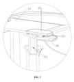
- this embodiment provides a pet water dispenser.
- the pet water dispenser includes a water storage tray 1, a filter rack 2, filter cotton 3, a water tank 10 and a water pump 6.
- the filter rack 2 is located below the water storage tray 1, the filter rack 2 is formed with a filter structure, and the filter structure is configured to receive and filter water overflowing from the water storage tray 1.
- the filtration precision of the filter structure is less than the filtration precision of the filter cotton 3, and the filter cotton 3 is configured to re-filter water filtered by the filter structure.
- the water tank 10 is located below the filter cotton 3.
- the water pump 6 is configured to pump water within the water tank 10 to the water storage tray 1.
- the water pump 6 pumps the water within the water tank 10 to the water storage tray 1.
- the filter structure on the filter rack 2 preliminarily filters the water that overflows to the filter rack 2, mainly filtering out hair, large particles and others.
- the water flows to the filter cotton 3 below the filter rack 2.
- the filter cotton 3 is used for re-filtration. Since the large particles and the hair in the water have been filtered out by the filter structure before the filter cotton 3, the hair and the large particles can be prevented from adhering to the filter cotton 3 effectively.
- the water filtered by the filter cotton 3 flows to the water tank 10, slowing down the cleaning frequency of the filter cotton 3 and prolonging the service life of the filter cotton 3.
- the filter rack 2 is provided with multiple through holes extending from top to bottom, and the multiple through holes form the filter structure. Large particles and hair cannot pass through the multiple through holes so that the large particles and the hair in the water can be filtered out.
- the multiple through holes allow a larger water flow to pass through the filter rack 2 so that the filtration efficiency can be increased.
- each of the multiple through holes is tapered holes having a narrow top and a wide bottom, which can not only play a filtration role but also prevent the multiple through holes from being clogged, allowing the water flow to pass through the multiple through holes quickly.
- the water storage tray 1 is provided with a water overflow outlet 7, the water overflow outlet 7 is higher than the lowest position of the inner wall of the water storage tray 1, and when reaching the height of the water overflow outlet 7, the water within the water storage tray 1 flows to the filter structure from the water overflow outlet 7.
- the water overflow outlet 7 is an elongated hole extending horizontally so that the water in the water storage tray 1 can overflow timely, thereby preventing the water in the water storage tray 1 from overflowing outside the pet water dispenser from the top of the water storage tray 1 due to untimely overflow.
- the water storage tray 1 is configured as an elliptical disc-shaped structure having a top opening, and the water overflow outlet 7 is disposed at one end of the water storage tray 1 in a long axial direction of the elliptical disc-shaped structure.
- the filter rack 2 is inclined with respect to a horizontal direction, and one end of the filter rack 2 close to the water overflow outlet 7 is higher than the other end of the filter rack 2 so that the water overflowing from the water overflow outlet 7 can cover the entire surface of the filter rack 2, increasing the area in which the filter rack 2 can contact the water flow and increasing the filtration effect.
- the water storage tray 1 is disposed on the top of the water tank 10, and the filter rack 2 and the filter cotton 3 are disposed within the water tank 10.
- the internal filter cotton 3 and filter rack 2 can be protected from external pollution, prolonging the service life, and the water storage tray 1 is disposed on the top of the water tank 10, facilitating drinking water by pets.
- the water storage tray 1 is detachably connected to the water tank 10
- the filter rack 2 is detachably connected to the water tank 10
- a handle protrudes from one side of the filter rack 2 facing the water storage tray 1 so that the filter rack 2 can be taken out easily when cleaning.
- the filter rack 2 and the handle are formed integrally, the shape of the handle on the filter rack 2 may be any shape, and the filter bracket 2 is a plastic rack with a low cost.
- the water tank 10 includes a lower housing 16 having a top opening and an upper cover 11 mounted onto the lower housing 16 to seal the top opening.
- the water storage tray 1 is mounted onto the upper cover 11.
- the water storage tray 1 is detachably connected to the upper cover 11.
- the filter rack 2 is detachably mounted within the lower housing 16.
- a circumferential edge of the top opening of the water storage tray 1 is provided with a tray flange 18, the upper cover 11 is provided with a penetrating hole extending along an up-down direction, a lower end of the water storage tray 1 passes through the penetrating hole and enters the water tank 10, the opening end surface of an upper end of the penetrating hole forms a tray support surface, and the tray flange 18 is located over the upper cover 11 and is supported by the tray support surface so that the upper cover 11 can support the water storage tray 1.
- the tray flange 18 is formed with a notch 21 on a first side of the water storage tray 1 in the horizontal direction
- the upper cover 11 is provided with a water inlet plate 19
- the water inlet plate 19 passes through the notch 21 and extends into the water storage tray 1, and the water inlet plate 19 downward presses the inner bottom wall of the notch 21.
- a second side of the water storage tray 1 in the horizontal direction is clamped to the upper cover 11 through a latch 20, the latch 20 can slide along the horizontal direction with respect to the upper cover 11, the horizontal direction is the long axial direction of the elliptical disc-shaped structure, and the latch 20 and the notch 21 are located at two ends of the tray flange 18 in a preset horizontal direction respectively.
- the horizontal direction is roughly a left-right direction as shown in FIG. 1 .
- a latch mounting space is formed between the upper cover 11 and the lower housing 16.
- the latch 20 extends along the horizontal direction.
- a right end of the latch 20 slides into the latch mounting space along the horizontal direction.
- the upper cover 11 is provided with an upper opening.
- a lower end of the upper opening communicates with the latch mounting space.
- a left end of the latch 20 extends out of the latch mounting space and downward presses the upper surface of the tray flange 18.
- An operation portion 17 protrudes from the upper surface of one end of the latch 20 extending out of the latch mounting space.
- the lower surface of the latch 20 forms the limit surface 8.
- the limit surface 8 can abut against the left sidewall of the upper opening along the preset horizontal direction, and the operation portion 17 can abut against the right sidewall of the upper opening along the horizontal direction.
- the limit surface 8 abuts against the left sidewall of the upper opening along the preset horizontal direction, the left end of the latch 20 presses the upper surface of the tray flange 18, and the operation portion 17 and the right sidewall of the upper opening are spaced apart so that the water storage tray 1 and the upper cover 11 can be clamped by the latch 20.
- the operation portion 17 When it is necessary to disassemble the water storage tray 1, the operation portion 17 is pushed to the right to drive the latch 20 to slide to the right so that before the operation portion 17 abuts against the right sidewall of the upper opening or at the same time, the left end of the latch 20 can be completely detached from the tray flange 18, thereby causing a right side of the tray flange 18 to lose the limit on the latch 20.
- the water storage tray 1 After the right side of the tray flange 18 is slightly lifted upward, the water storage tray 1 may be pulled to the right so that the water inlet plate 19 can come out of the notch 21, thereby disassembling the entire water storage tray 1.
- the upper cover 11 is provided with a water inlet channel 12, a first end of the water inlet channel 12 horizontally extends into the water storage tray 1, a water outlet of the water pump 6 is connected to a water pipe 13, and a water outlet of the water pipe 13 communicates with the water inlet channel 12.
- the upper cover 11 is directly provided with the water inlet channel 12, simplifying the entire structure of the pet water dispenser and reducing the number of parts.
- a second end of the water inlet channel 12 forms a water supply mouth 14, the water supply mouth 14 passes through the upper cover 11 along a vertical direction, an upper end of the water pipe 13 communicates with the water supply mouth 14; the upper cover 11 is provided with a dust cover 15, and the dust cover 15 covers the end surface of a top opening of the water supply mouth 14.
- the dust cover 15 can prevent dust from entering the water supply mouth 14 to clog the water supply mouth 14.
- one end of the water inlet channel 12 is opened on the water inlet plate 19, the upper cover 11 is provided with a vertical pipe, the vertical pipe and the upper cover 11 are formed integrally, the inner cavity of the vertical pipe forms the preceding water supply mouth 14, a lower end of the vertical pipe is inserted into the upper end of the water pipe 13 so that when the upper cover 11 is convenient to disassemble, the vertical pipe can come out of the upper end of the water pipe 13.
- the pet water dispenser further includes a filter element rack 4.
- the filter element rack 4 is located under the filter cotton 3, and a placement cavity 9 is formed between the filter element rack 4 and the filter cotton 3 and is configured to place a charcoal pack.
- the charcoal pack When placed within the placement cavity, the charcoal pack may be used for absorbing and filtering the water filtered by the filter cotton 3, improving the quality of the filtered water.
- the water tank 10 further includes a support rack 5, the support rack 5 is connected to the lower housing 16, a circumferential edge of the filter element rack 4 is provided with a support flange, the inner wall of the support rack 5 is provided with the support surface configured to support the support flange; a circumferential edge of the filter rack 2 presses a circumferential edge of the filter cotton 3 against the upper surface of the support flange.
- the support rack 5, the supporting filter cotton 3, the filter rack 2 and the filter element rack 4 can be used for making the filter cotton 3, the filter rack 2 and the filter element rack 4 detachable.
- the filter element rack 4 is provided with a water passing hole
- the support rack 5 may be a hollow structure or a water passing structure configured to enable water falling on the support rack 5 to return to the bottom of the water tank 10 to prevent the filter element rack 4 and the support rack 5 from affecting the water filtered by the filter cotton 3 back to the bottom of the water tank 10.
Landscapes
- Life Sciences & Earth Sciences (AREA)
- Environmental Sciences (AREA)
- Animal Husbandry (AREA)
- Biodiversity & Conservation Biology (AREA)
- Feeding And Watering For Cattle Raising And Animal Husbandry (AREA)
- Devices For Dispensing Beverages (AREA)
Applications Claiming Priority (2)
| Application Number | Priority Date | Filing Date | Title |
|---|---|---|---|
| CN202321759983.8U CN220606940U (zh) | 2023-07-06 | 2023-07-06 | 宠物饮水机 |
| PCT/CN2023/126807 WO2025007454A1 (zh) | 2023-07-06 | 2023-10-26 | 宠物饮水机 |
Publications (2)
| Publication Number | Publication Date |
|---|---|
| EP4512239A1 true EP4512239A1 (de) | 2025-02-26 |
| EP4512239A4 EP4512239A4 (de) | 2026-03-11 |
Family
ID=90213456
Family Applications (1)
| Application Number | Title | Priority Date | Filing Date |
|---|---|---|---|
| EP23920282.3A Pending EP4512239A4 (de) | 2023-07-06 | 2023-10-26 | Haustierwasserspender |
Country Status (3)
| Country | Link |
|---|---|
| EP (1) | EP4512239A4 (de) |
| CN (1) | CN220606940U (de) |
| WO (1) | WO2025007454A1 (de) |
Family Cites Families (8)
| Publication number | Priority date | Publication date | Assignee | Title |
|---|---|---|---|---|
| CN209752261U (zh) * | 2019-01-30 | 2019-12-10 | 庹晶晶 | 一种宠物饮水机的过滤装置 |
| WO2022127750A1 (zh) * | 2020-12-14 | 2022-06-23 | 深圳前海霍曼科技有限公司 | 宠物饮水机 |
| CN216292557U (zh) * | 2021-09-22 | 2022-04-15 | 符文乐 | 一种带过滤结构的宠物饮水机 |
| CN113692986A (zh) * | 2021-09-22 | 2021-11-26 | 北京猫猫狗狗科技有限公司 | 防溢流结构、饮水组件及其宠物饮水机 |
| CN216906390U (zh) * | 2022-03-22 | 2022-07-08 | 合宠科技(青岛)有限公司 | 宠物饮水机 |
| DE202022103081U1 (de) * | 2022-05-31 | 2022-08-10 | Shenzhen Liyi99.Com, Ltd. | Haustiertrinkbrunnen |
| CN115250941B (zh) * | 2022-06-06 | 2025-12-30 | 深圳市金灿宠物用品有限公司 | 一种宠物饮水机 |
| CN115140874B (zh) * | 2022-06-27 | 2024-11-19 | 深圳市云视机器人有限公司 | 宠物饮水机 |
-
2023
- 2023-07-06 CN CN202321759983.8U patent/CN220606940U/zh active Active
- 2023-10-26 EP EP23920282.3A patent/EP4512239A4/de active Pending
- 2023-10-26 WO PCT/CN2023/126807 patent/WO2025007454A1/zh active Pending
Also Published As
| Publication number | Publication date |
|---|---|
| CN220606940U (zh) | 2024-03-19 |
| WO2025007454A1 (zh) | 2025-01-09 |
| EP4512239A4 (de) | 2026-03-11 |
Similar Documents
| Publication | Publication Date | Title |
|---|---|---|
| JP5584714B2 (ja) | エアー駆動式フィルタ装置 | |
| EP2434869B1 (de) | Haustiertränke | |
| CN116096530A (zh) | 用于物质去除机的竖管再循环系统 | |
| CN215940799U (zh) | 用于清洁装置的污水箱和清洁装置 | |
| EP4512239A1 (de) | Haustierwasserspender | |
| CN216159308U (zh) | 接水盘组件及具有其的空调器 | |
| CN112944656A (zh) | 接水盘组件及具有其的空调器 | |
| CN217012374U (zh) | 鱼粪收集器 | |
| JP2004132317A (ja) | オイルパン | |
| CN209835718U (zh) | 一种用于农村厨房污水治理的简易隔油池 | |
| KR102697253B1 (ko) | 반려동물용 급수기 | |
| CN219270750U (zh) | 油壶 | |
| JP3076766B2 (ja) | 観賞魚水槽用濾過装置の筒状パイプジョイント | |
| CN220000370U (zh) | 一种宠物饮水机水箱以及宠物饮水机 | |
| CN219185978U (zh) | 过滤组件及宠物饮水机 | |
| CN223125579U (zh) | 一种排污装置及宠物饮水机 | |
| CN222707364U (zh) | 一种低水位进水并防脏物回流的过滤结构及过滤器 | |
| CN211881683U (zh) | 一种宠物饮水器 | |
| CN223639918U (zh) | 一种宠物饮水机 | |
| CN223126475U (zh) | 隔板构件及洗碗机 | |
| CN223281388U (zh) | 一次性水槽防滤网 | |
| CN223126480U (zh) | 洗碗机 | |
| CN223472821U (zh) | 一种宠物饮水机 | |
| CN222584426U (zh) | 污水箱、清洁设备和清洁系统 | |
| CN216931377U (zh) | 饮水机的饮水装置及饮水机 |
Legal Events
| Date | Code | Title | Description |
|---|---|---|---|
| STAA | Information on the status of an ep patent application or granted ep patent |
Free format text: STATUS: UNKNOWN |
|
| STAA | Information on the status of an ep patent application or granted ep patent |
Free format text: STATUS: THE INTERNATIONAL PUBLICATION HAS BEEN MADE |
|
| PUAI | Public reference made under article 153(3) epc to a published international application that has entered the european phase |
Free format text: ORIGINAL CODE: 0009012 |
|
| STAA | Information on the status of an ep patent application or granted ep patent |
Free format text: STATUS: REQUEST FOR EXAMINATION WAS MADE |
|
| 17P | Request for examination filed |
Effective date: 20240813 |
|
| AK | Designated contracting states |
Kind code of ref document: A1 Designated state(s): AL AT BE BG CH CY CZ DE DK EE ES FI FR GB GR HR HU IE IS IT LI LT LU LV MC ME MK MT NL NO PL PT RO RS SE SI SK SM TR |
|
| RIN1 | Information on inventor provided before grant (corrected) |
Inventor name: WU, JIE |
|
| A4 | Supplementary search report drawn up and despatched |
Effective date: 20260209 |
|
| RIC1 | Information provided on ipc code assigned before grant |
Ipc: A01K 7/00 20060101AFI20260203BHEP Ipc: A01K 7/02 20060101ALI20260203BHEP |