EP4510777A1 - Liquid heating device - Google Patents
Liquid heating device Download PDFInfo
- Publication number
- EP4510777A1 EP4510777A1 EP22937516.7A EP22937516A EP4510777A1 EP 4510777 A1 EP4510777 A1 EP 4510777A1 EP 22937516 A EP22937516 A EP 22937516A EP 4510777 A1 EP4510777 A1 EP 4510777A1
- Authority
- EP
- European Patent Office
- Prior art keywords
- ceramic heaters
- container
- safety device
- ceramic
- liquid heating
- Prior art date
- Legal status (The legal status is an assumption and is not a legal conclusion. Google has not performed a legal analysis and makes no representation as to the accuracy of the status listed.)
- Pending
Links
Images






Classifications
-
- H—ELECTRICITY
- H05—ELECTRIC TECHNIQUES NOT OTHERWISE PROVIDED FOR
- H05B—ELECTRIC HEATING; ELECTRIC LIGHT SOURCES NOT OTHERWISE PROVIDED FOR; CIRCUIT ARRANGEMENTS FOR ELECTRIC LIGHT SOURCES, IN GENERAL
- H05B3/00—Ohmic-resistance heating
- H05B3/78—Heating arrangements specially adapted for immersion heating
- H05B3/82—Fixedly-mounted immersion heaters
-
- F—MECHANICAL ENGINEERING; LIGHTING; HEATING; WEAPONS; BLASTING
- F24—HEATING; RANGES; VENTILATING
- F24H—FLUID HEATERS, e.g. WATER OR AIR HEATERS, HAVING HEAT-GENERATING MEANS, e.g. HEAT PUMPS, IN GENERAL
- F24H1/00—Water heaters, e.g. boilers, continuous-flow heaters or water-storage heaters
- F24H1/10—Continuous-flow heaters, i.e. heaters in which heat is generated only while the water is flowing, e.g. with direct contact of the water with the heating medium
- F24H1/101—Continuous-flow heaters, i.e. heaters in which heat is generated only while the water is flowing, e.g. with direct contact of the water with the heating medium using electric energy supply
- F24H1/102—Continuous-flow heaters, i.e. heaters in which heat is generated only while the water is flowing, e.g. with direct contact of the water with the heating medium using electric energy supply with resistance
-
- F—MECHANICAL ENGINEERING; LIGHTING; HEATING; WEAPONS; BLASTING
- F24—HEATING; RANGES; VENTILATING
- F24H—FLUID HEATERS, e.g. WATER OR AIR HEATERS, HAVING HEAT-GENERATING MEANS, e.g. HEAT PUMPS, IN GENERAL
- F24H15/00—Control of fluid heaters
- F24H15/10—Control of fluid heaters characterised by the purpose of the control
- F24H15/128—Preventing overheating
-
- F—MECHANICAL ENGINEERING; LIGHTING; HEATING; WEAPONS; BLASTING
- F24—HEATING; RANGES; VENTILATING
- F24H—FLUID HEATERS, e.g. WATER OR AIR HEATERS, HAVING HEAT-GENERATING MEANS, e.g. HEAT PUMPS, IN GENERAL
- F24H9/00—Details
- F24H9/0005—Details for water heaters
- F24H9/001—Guiding means
- F24H9/0015—Guiding means in water channels
-
- F—MECHANICAL ENGINEERING; LIGHTING; HEATING; WEAPONS; BLASTING
- F24—HEATING; RANGES; VENTILATING
- F24H—FLUID HEATERS, e.g. WATER OR AIR HEATERS, HAVING HEAT-GENERATING MEANS, e.g. HEAT PUMPS, IN GENERAL
- F24H9/00—Details
- F24H9/18—Arrangement or mounting of grates or heating means
- F24H9/1809—Arrangement or mounting of grates or heating means for water heaters
- F24H9/1818—Arrangement or mounting of electric heating means
-
- F—MECHANICAL ENGINEERING; LIGHTING; HEATING; WEAPONS; BLASTING
- F24—HEATING; RANGES; VENTILATING
- F24H—FLUID HEATERS, e.g. WATER OR AIR HEATERS, HAVING HEAT-GENERATING MEANS, e.g. HEAT PUMPS, IN GENERAL
- F24H9/00—Details
- F24H9/20—Arrangement or mounting of control or safety devices
- F24H9/2007—Arrangement or mounting of control or safety devices for water heaters
- F24H9/2014—Arrangement or mounting of control or safety devices for water heaters using electrical energy supply
- F24H9/2028—Continuous-flow heaters
-
- H—ELECTRICITY
- H05—ELECTRIC TECHNIQUES NOT OTHERWISE PROVIDED FOR
- H05B—ELECTRIC HEATING; ELECTRIC LIGHT SOURCES NOT OTHERWISE PROVIDED FOR; CIRCUIT ARRANGEMENTS FOR ELECTRIC LIGHT SOURCES, IN GENERAL
- H05B3/00—Ohmic-resistance heating
- H05B3/40—Heating elements having the shape of rods or tubes
- H05B3/42—Heating elements having the shape of rods or tubes non-flexible
- H05B3/48—Heating elements having the shape of rods or tubes non-flexible heating conductor embedded in insulating material
-
- H—ELECTRICITY
- H05—ELECTRIC TECHNIQUES NOT OTHERWISE PROVIDED FOR
- H05B—ELECTRIC HEATING; ELECTRIC LIGHT SOURCES NOT OTHERWISE PROVIDED FOR; CIRCUIT ARRANGEMENTS FOR ELECTRIC LIGHT SOURCES, IN GENERAL
- H05B2203/00—Aspects relating to Ohmic resistive heating covered by group H05B3/00
- H05B2203/021—Heaters specially adapted for heating liquids
Definitions
- the present invention relates to a ceramic heater suitable for heating a liquid such as water, and a liquid heating device using the same.
- Warm water is needed for a warm water washing toilet seat, a fuel cell system, a water heater, a 24-hour bath system, heating of a washer fluid for a vehicle, an in-vehicle air conditioner, and the like. Accordingly, a liquid heating device which heats water by a built-in heater is used.
- a rod-shaped ceramic heater having a heat generation portion embedded in a ceramic sheet wrapped around the outer circumference of an elongated ceramic base is used.
- Patent Document 1 technology of providing a safety device (such as thermal fuse) for interrupting energization to a heater when the temperature of the heater has abnormally increased and thus a device temperature has become high, is developed (Patent Document 1).
- Patent Document 1 Japanese Patent Application Laid-Open (kokai) No. 2013-104649
- an object of the present invention is to provide a liquid heating device that achieves size reduction and enables heater energization to be assuredly interrupted at the time of abnormality, while a safety device is provided for a plurality of ceramic heaters.
- a liquid heating device of the present invention is a liquid heating device comprising: a container having an internal space, and an inlet and an outlet which communicate with the internal space; a plurality of ceramic heaters which extend in a front-rear direction and whose front-end portions are located in the internal space, the ceramic heaters having heat generation portions at the front-end portions; and a safety device configured to interrupt energization to the ceramic heaters when a temperature of the container has exceeded a set value, wherein in a process in which a liquid is introduced from the inlet and flows through the internal space to the outlet, the liquid is heated by the ceramic heaters, the ceramic heaters are arranged side by side with each other along the front-rear direction, the safety device whose number is smaller than a number of the ceramic heaters is provided on an outer side of the container or buried in the container, and in a cross-section crossing the front-rear direction, one said safety device is provided inside an area between two lines which pass centers of gravity of at least a
- the size of the liquid heating device can be reduced as compared to a case of providing safety devices whose number is the same as ceramic heaters.
- one safety device is provided inside the area for at least a pair of two adjacent ceramic heaters, the safety device is close to both of the pair of two adjacent ceramic heaters.
- abnormal temperature increase of each ceramic heater can be sufficiently detected, and heater energization can be assuredly interrupted at the time of abnormality.
- the safety device may be provided on an outer side of the container, a heat-transfer medium having a thermal conductivity higher than a thermal conductivity of the container may be further provided between the safety device and the container, and an outer surface of the container in the area may have a recess at a part contacting with the heat-transfer medium.
- At least a part of the safety device may be located on an inner side of the recess.
- the present invention it becomes possible to provide a liquid heating device that achieves size reduction and enables heater energization to be assuredly interrupted at the time of abnormality, while a safety device is provided for a plurality of ceramic heaters.
- FIG. 1 is a perspective view of a liquid heating device 200 according to the first embodiment of the present invention.
- FIG. 2 is a see-through view along line A-A in FIG. 1 .
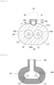
- FIG. 3 is a sectional view along line B-B in FIG. 1 .
- FIG. 4 is a sectional view along line C-C in FIG. 3 .
- FIG. 5 is a sectional view along line D-D in FIG. 3 .
- FIG. 6 is a sectional view along line E-E in FIG. 3 .
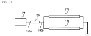
- FIG. 7 is a schematic diagram showing a connection circuit of ceramic heaters 171, 172 and a safety device 150.
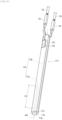
- FIG. 8 is a perspective view showing the outer appearance of a ceramic heater 171.
- FIG. 9 is an exploded perspective view of the ceramic heater 171.
- the liquid heating device 200 is provided to a warm water washing toilet seat, and heats ordinary-temperature water by two built-in ceramic heaters 171, 172, to supply warm water.
- the liquid heating device 200 has substantially an oblong tubular shape (a tubular shape whose cross-section is a rectangle with rounded corners) extending in an axial-line-L direction in its entirety, and has a container 100, two ceramic heaters 171, 172, and one safety device 150.
- the container 100 has an oblong tubular trunk portion 101 having an internal space 100i for storing a liquid W (water), a front-end lid 107 and a rear-end lid 109 that close openings at both ends in the axial direction of the trunk portion 101, and an inlet 103 and an outlet 105 for the liquid W which are provided integrally with the trunk portion 101.
- a liquid W water
- a front-end lid 107 and a rear-end lid 109 that close openings at both ends in the axial direction of the trunk portion 101
- an inlet 103 and an outlet 105 for the liquid W which are provided integrally with the trunk portion 101.
- Both ends in the axial direction of the trunk portion 101 protrude in a flange shape in the radial direction. Both ends of the trunk portion 101, and the front-end lid 107 and the rear-end lid 109, are respectively sealed with each other in an airtight state by O rings 190 ( FIG. 3 ).
- the ceramic heaters 171, 172 have rod shapes extending in an front-rear direction AX, and are arranged side by side toward the same direction (in parallel) along the front-rear direction AX.
- a base-end portion 17R of each ceramic heater 171, 172 is retained in a cantilever manner by a sealing portion 180 at an opening of the rear-end lid 109 of the container 100, whereby each ceramic heater 171, 172 is attached to the container 100.
- a front-end portion 17T of each ceramic heater 171, 172 is located in the internal space 100i. Needless to say, the retained part by the sealing portion 180 is on the base-end side relative to a heat generation portion 17a of the ceramic heater described later.
- Lead wires 15, 16 described later for supplying power from outside are connected to the base-end portion 17R sides of the ceramic heaters 171, 172.
- the axial direction of the trunk portion 101 is parallel to the axial-line-L direction, and the ceramic heaters 171, 172 are stored in the internal space 100i of the trunk portion 101 such that the direction(the front-rear direction AX) in which the ceramic heaters 171, 172 are arranged side by side is along the axial-line-L direction.
- the liquid heating device 200 is provided to the warm water washing toilet seat such that the axial-line-L direction is substantially the horizontal direction and the outlet 105 side is located slightly upward, and the ceramic heaters 171, 172 are laid horizontally.
- the inlet 103 and the outlet 105 communicate with the internal space 100i and are located apart from each other in the axial-line-L direction.
- the liquid W introduced through the inlet 103 from outside passes through the internal space 100i along the axial-line-L direction and then is discharged from the outlet 105.
- a gap is formed between the inner wall of the container 100 and each ceramic heater 171, 172.
- the liquid W introduced into the internal space 100i through the inlet 103 contacts with the outer surfaces of the ceramic heaters 171, 172 along the axial-line-L direction, thus being heated, and then the liquid W flows to the outlet 105.
- FIG. 2 is a view as seen through in a direction perpendicular to the axial-line-L direction and the axial line of the inlet 103.
- the safety device 150 whose number is smaller (in this example, one) than the number of the ceramic heaters 171, 172 (in this example, two) is provided on the outer side of the container 100.
- a box-shaped grease case 140 is formed integrally on the outer surface of the container 100 between the inlet 103 and the outlet 105, and thermal grease (heat-transfer medium) 160 is included inside the grease case 140.
- the safety device 150 is buried in the thermal grease 160.
- the grease case 140 includes a box-shaped storage portion 141 which opens on the upper side, and a cover 142 which covers the upper side of the storage portion 141.
- the storage portion 141 is integrated with the container 100.
- the cover 142 is attached thereto.
- the safety device 150 may be configured to interrupt energization to the ceramic heaters 171, 172 when the temperature of the container 100 exceeds a set value.
- the safety device 150 is a known pellet-type thermal fuse, and a first lead wire 150a and a second lead wire 150b extend from both ends of the safety device 150.
- a first lead wire 150a and a second lead wire 150b extend from both ends of the safety device 150.
- parts of wall surfaces respectively facing the inlet 103 and the outlet 105 are cut out, and the first lead wire 150a and the second lead wire 150b are exposed to outside through the respective cutouts.
- the first lead wire 150a is connected on the side of a power supply PW for the ceramic heaters 171, 172, and the two ceramic heaters 171, 172 are connected in parallel to the second lead wire 150b.
- the first lead wire 150a may be connected to the ground side and the second lead wire 150b may be connected to the side of the power supply PW.
- the thermal conductivity of the heat-transfer medium 160 such as thermal grease is higher than the thermal conductivity of the container 100.
- the heat-transfer medium is not limited to thermal grease, and may be a heat-transfer medium made of resin and metal powder, for example.
- the heat-transfer medium such as thermal grease may be a curable type. In a case of a curable type, the grease case 140 is not needed and the safety device 150 may be retained at the outer surface of the container 100 via the curable-type heat-transfer medium.
- curable-type heat-transfer medium is curable-type silicone thermal grease.
- a separation wall 100s is provided for separating the plurality of ceramic heaters 171, 172 one by one from each other, so that the water introduced from the inlet 103 flows for each ceramic heater 171, 172 in the separation wall 100s.
- the separation wall 100s is not provided and therefore a single internal space 100i is formed.
- the volume of the internal space 100i increases, so that boiling bubbles generated on the inlet 103 side is readily discharged from the outlet 105 to outside.
- flows of water heated in each individual separation wall 100s merge together, thus obtaining warm water having uniform temperature.
- FIG. 3 is a sectional view taken along the axial-line-L direction so as to pass the center of the minor axis of the liquid heating device 200.
- FIG. 4 and FIG. 6 are sectional views perpendicular to the axial-line-L direction in FIG. 3 .
- a segment M1 is drawn so as to connect centers of gravity G1, G2 of a pair of two adjacent ceramic heaters 171, 172.
- two lines S1, S2 are drawn perpendicularly to the segment M1 so as to pass the centers of gravity G1, G2, respectively.
- One safety device 150 is provided inside an area R1 between the lines S1, S2.
- the size of the liquid heating device 200 can be reduced as compared to a case of providing safety devices whose number is the same as the number of ceramic heaters.
- one safety device 150 is provided inside the area R1 for at least a pair of two adjacent ceramic heaters 171, 172, the safety device 150 is close to both of the pair of two adjacent ceramic heaters 171, 172.
- abnormal temperature increase of each ceramic heater 171, 172 can be sufficiently detected, and heater energization can be assuredly interrupted at the time of abnormality.
- the outer surface of the container 101 in the area R1 has a recess 101r at a part contacting with the heat-transfer medium 160.
- the heat-transfer medium 160 for transferring heat of the ceramic heaters 171, 172 to the safety device 150 is interposed in the recess 101r, so that the heat-transfer medium 160 becomes closer to the ceramic heaters 171, 172, whereby abnormal temperature increase of each ceramic heater 171, 172 can be more assuredly detected.
- the recess 101r has substantially a wedge shape in which the intersection part of circles enclosing the respective ceramic heaters 171, 172 is the deepest.
- the recess 101r is provided on the inner side of the storage portion 141.
- the contour of the container 101 at a part where the heat-transfer medium 160 is interposed is at least partially present on the inner side of the container 101 (side close to ceramic heaters 171, 172) from an approximation curve P passing the contour of the container 101 at a part where the heat-transfer medium 160 is not interposed, the inner side part is regarded as a recess.
- the safety device 150 is located on the inner side of the recess 101r.
- a part of the safety device 150 is present in the recess 101r, so that the safety device 150 becomes closer to the ceramic heaters 171, 172, whereby abnormal temperature increase of the ceramic heaters 171, 172 can be more assuredly detected.
- the ceramic heaters 171, 172 have the same shape and therefore the ceramic heater 171 will be described.
- the ceramic heater 171 has a heat generation body 17h which generates heat by being energized from outside via the lead wires 15, 16.
- the heat generation body 17h has, on the front-end side, the heat generation portion 17a formed by meandering a conductor in the front-rear direction AX as a heat generation pattern, and has a pair of lead portions 17b led from both ends of the heat generation portion 17a to the rear-end side.
- the heat generation portion 17a has a length of Lh in the front-rear direction AX.
- the heat generation body 17h has the heat generation portion 17a, both lead portions 17b, and electrode patterns 17c formed at rear ends of both lead portions 17b, and the heat generation body 17h is held between two ceramic green sheets 17s1, 17s2.
- the ceramic green sheets alumina is used.
- the heat generation portion 17a and the lead portions 17b tungsten, rhenium, or the like is used.
- Two electrode pads 17p to which lead terminals 18 (see FIG. 8 ) are to be brazed are formed on the front surface of the ceramic green sheet 17s2, and the electrode patterns 17c are connected to the electrode pads 17p via through holes, thus forming a laminated body of the ceramic green sheets.
- this laminated body is wrapped around a rod-shaped ceramic base 17g mainly composed of alumina, etc., with the ceramic green sheet 17s2 set on the front side, and then these are sintered, whereby the ceramic green sheets 17s1, 17s2 form a ceramic sheet 17s wrapped around the outer circumference of the ceramic base 17g so as to be integrated and thus the ceramic heater 171 can be produced.
- the ceramic base 17g may have a tubular shape having a through hole, or a columnar shape with no hole. In a case of a tubular shape, it is desirable to make sealing with resin or the like so as not to leak water from the through hole.
- the lead wires 15, 16 are crimped with the lead terminals 18 so as to be electrically connected thereto (see FIG. 8 ).
- the laminated body in wrapping the laminated body around the ceramic base 17g, is wrapped such that both ends along the front-rear direction AX of the laminated body are spaced from each other.
- a slit 17v forming a recessed groove along the front-rear direction AX is formed as a non-heat generation portion.
- the heat generation portion 17a is embedded in the ceramic heater 171 so as to form a ring shape having ends, and the slit 17v as a non-heat generation portion is formed between two ring ends 17e of the heat generation portion 17a.
- FIG. 10 is a sectional view of the liquid heating device according to the second embodiment of the present invention, and is a sectional view corresponding to FIG. 5 .
- the liquid heating device according to the second embodiment of the present invention is the same as the liquid heating device 200 according to the first embodiment except that the placement position of the safety device 150 and thus the configuration of a container 110 are different. Therefore, the same parts as those of the liquid heating device 200 are denoted by the same reference characters and the description thereof is omitted.
- one safety device 150 is buried in the container 110. Specifically, the interval between the ceramic heaters 171, 172 is expanded so that a separation wall 100s2 wider than the separation wall 100s of the container 100 shown in FIG. 3 in the first embodiment is formed, and the safety device 150 is buried in the separation wall 100s2.
- the size of the liquid heating device can be reduced as compared to a case of providing safety devices whose number is the same as the number of ceramic heaters.
- the safety device 150 is close to both of the pair of two adjacent ceramic heaters 171, 172.
- abnormal temperature increase of each ceramic heaters 171, 172 can be sufficiently detected, and heater energization can be assuredly interrupted at the time of abnormality.
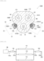
- FIG. 11 is a perspective view showing the outer appearance of the liquid heating device 200B
- FIG. 12 is a sectional view of the liquid heating device 200B.
- FIG. 12 is a sectional view corresponding to FIG. 5 in the first embodiment.
- the liquid heating device 200B is the same as the liquid heating device 200 according to the first embodiment except that three ceramic heaters 171, 172, 173 and two safety devices 151, 152 are provided and the configuration of a container 100B is different. Therefore, the same parts as those of the liquid heating device 200 are denoted by the same reference characters and the description thereof is omitted.
- the liquid heating device 200B includes the container 100B having substantially a triangular tubular shape (a tubular shape whose cross-section is a triangle) in its entirety, and the three ceramic heaters 171 to 173.
- the container 100B has an oblong tubular trunk portion 101B having an internal space 100i for storing a liquid (water), a front-end lid 107B and a rear-end lid 108 that close openings at both ends in the axial-line-L direction of the trunk portion 101B, and an inlet 103B and an outlet 105B for the liquid W.
- the inlet 103B and the outlet 105B are provided integrally with the front-end lid 107B and the trunk portion 101B, respectively.
- the front-end lid 107B is fitted to the front end in the axial-line-L direction of the trunk portion 101 (end on the side where the ceramic heaters 171 to 173 are exposed).
- the rear-end lid 108 is sealed in a liquid-tight state via a rubber seal such as a packing, for example.
- the three ceramic heaters 171 to 173 have rod shapes extending in the front-rear direction AX, and extend in the same direction (in parallel).
- Base-end portions 17R of the ceramic heaters 171 to 173 penetrate three openings 107m1 to 107m3 of the front-end lid 107B. Gaps between the ceramic heaters 171 to 173 and the openings 107m1 to 107m3 are sealed by a fixation member 185 made of epoxy resin, whereby the ceramic heaters 171 to 173 are fixed to the container 100 in a cantilever manner.
- the ceramic heaters 171 to 173 are stored in the internal space 100i of the trunk portion 101 such that the front-rear direction AX, i.e., the direction in which the ceramic heaters 171 to 173 are arranged side by side, is along the axial-line-L direction of the trunk portion 101.
- the inlet 103B and the outlet 105B communicate with the internal space 100Bi ( FIG. 12 ) and are located apart from each other in the axial-line-L direction.
- the liquid introduced through the inlet 103B from outside passes through the internal space 100Bi along the axial-line-L direction and then is discharged from the outlet 105B.
- a gap is formed between the inner wall of the container 100 and each ceramic heater 171 to 173.
- the liquid introduced into the internal space 100Bi through the inlet 103 contacts with the outer surfaces of the ceramic heaters 171 to 173 along the axial-line-L direction, thus being heated, and then the liquid flows to the outlet 105.
- the safety devices 151, 152 whose number is smaller (in this example, two) than the number of the ceramic heaters 171 to 173 (in this example, three) are provided on the outer side of the container 100B.
- box-shaped grease cases 140B1, 140B2 are formed integrally on two of three outer surfaces of the container 100B between the inlet 103B and the outlet 105B.
- the grease cases 140B1, 140B2 have the same structure as that of the grease case 140 in the first embodiment.
- the thermal grease (heat-transfer medium) 160 is included inside each grease case 140B1, 140B2.
- Each safety device 151, 152 is buried in the thermal grease 160.
- a segment M1 is drawn so as to connect centers of gravity G1, G2 of a pair of two adjacent ceramic heaters 171, 172, and two lines S1, S2 are drawn. Then, one safety device 151 is provided inside an area R1 between the lines S1, S2.
- the size of the liquid heating device 200B can be reduced as compared to a case of providing safety devices whose number is the same as the number of ceramic heaters.
- one safety device 151 is provided inside the area R1 for a pair of two adjacent ceramic heaters 171, 172, and one safety device 152 is provided inside the area R2 for another pair of two adjacent ceramic heaters 171, 173. Therefore, the safety device 151 is close to both of the pair of two adjacent ceramic heaters 171, 172, and similarly, the safety device 152 is close to both of the other pair of two adjacent ceramic heaters 171, 173. Thus, abnormal temperature increase of each ceramic heater 171 to 173 can be sufficiently detected, and heater energization can be assuredly interrupted at the time of abnormality.
- the outer surface of the container 101B in the area R1 has a recess 101Br1 at a part contacting with the heat-transfer medium 160.
- the outer surface of the container 101B in the area R2 has a recess 101Br2 at a part contacting with the heat-transfer medium 160.
- the heat-transfer medium 160 for transferring heat of the ceramic heaters 171, 172 to the safety device 151 is interposed in the recess 101Br1.
- the heat-transfer medium 160 for transferring heat of the ceramic heaters 171, 173 to the safety device 152 is interposed in the recess 101Br2. Therefore, the heat-transfer mediums 160 become closer to the ceramic heaters 171 to 173, whereby abnormal temperature increase of each ceramic heater 171 to 173 can be more assuredly detected.
- the recesses 101Br1, 101Br2 respectively have substantially wedge shapes in which the intersection part of circles enclosing the ceramic heaters 171, 172 and the intersection part of circles enclosing the ceramic heaters 171, 173 are the deepest.
- the recesses 101Br1, 101Br2 are provided on the inner sides of the storage portions of the grease cases 140B1, 140B2, respectively.
- At least parts (in FIG. 5 , the bottom sides) of the safety devices 151, 152 are located on the inner sides of the recesses 101Br1, 101Br2, respectively.
- parts of the safety devices 151, 152 are present in the recesses 101Br1, 101Br2, so that the safety devices 151, 152 become closer to the ceramic heaters 171 to 173, whereby abnormal temperature increase of each ceramic heater 171 to 173 can be more assuredly detected.
- a first lead wire 151a is connected on the side of the power supply PW for the ceramic heaters 171 to 173, and the three ceramic heaters 171 to 173 are connected in parallel to the second lead wire 151b.
- the three ceramic heaters 171 to 173 are connected in parallel to a first lead wire 152a, and a second lead wire 152b is connected to the ground side.
- the ceramic heater 173 may be directly connected to the side of the power supply PW not via the safety device 151, and the ceramic heater 172 may be directly connected to the ground side not via the safety device 152.
- FIG. 14 is a sectional view of the liquid heating device according to the fourth embodiment of the present invention, and is a sectional view corresponding to FIG. 5 .
- the liquid heating device according to the fourth embodiment of the present invention is the same as the liquid heating device 200B according to the third embodiment except that the placement position of the safety device 150 and thus the configuration of a container 120 are different. Therefore, the same parts as those of the liquid heating device 200B are denoted by the same reference characters and the description thereof is omitted.
- one safety device 150 is buried in the container 120. Specifically, the intervals between the ceramic heaters 171 to 173 are expanded so that a separation wall 120s of the container 100 surrounded by the ceramic heaters 171 to 173 is made wider, and the safety device 150 is buried in the separation wall 120s.
- the size of the liquid heating device can be reduced as compared to a case of providing safety devices whose number is the same as the number of ceramic heaters.
- one safety device 151 may be provided for three ceramic heaters 171 to 173.
- two safety devices 153, 154 may be provided for four ceramic heaters 171 to 174.
- one safety device 154 may be provided inside the area R2 for a pair of the ceramic heaters 173, 174.
- an example of a connection circuit of the ceramic heaters 171 to 174 and the safety devices 153, 154 is as follows.
- a first lead wire 153a is connected on the side of the power supply PW for the ceramic heaters 171, 172, and two ceramic heaters 171, 172 are connected in parallel to a second lead wire 153b.
- a first lead wire 154a is connected on the side of the power supply PW for the ceramic heaters 173, 174, and two ceramic heaters 173, 174 are connected in parallel to the second lead wire 154b.
- one recess 130Br may be provided and the recess 130Br may extend deeply to the center of a container 130 surrounded by the ceramic heaters 171 to 173.
- one safety device 150 is provided at the deepest part of the recess 130Br, and the heat-transfer medium 160 is interposed between the recess 130Br and the safety device 150.
- the liquid heating device 200 shown in FIG. 1 was produced.
- alumina powder and glass-component powder serving as a sintering aid were crushed and mixed with water by a mill, and then were mixed with a binder, to obtain a clay-like mixture.
- the clay-like mixture was extruded by an extruder using a die with a core placed therein, to form a tubular ceramic base, which was then cut into a predetermined length and calcined.
- the outer diameter and the length of the ceramic base were adjusted in consideration of a sintering shrinkage factor.
- a heater pattern and a terminal portion connected thereto and leading to a sheet opposite surface were printed and formed using a tungsten/molybdenum paste.
- dimensions were prescribed while a shrinkage factor in ceramic sintering was taken into consideration.
- the heater pattern was formed while calculating a resistance value at the room temperature from a resistance value at a high temperature and a resistance change amount (temperature coefficient of resistance ⁇ temperature difference ⁇ initial resistance value) corresponding to temperature increase. Also for the sheet size, a sintering shrinkage factor was considered, to prepare and cut the sheet.
- the resistance value of the ceramic heater was adjusted by changing the length (number of times of folding) and the thickness of the heat generation portion.
- An exposed terminal portion of the heater sintered body was plated with Ni, and a lead portion made of Ni was brazed and joined thereto by Ag solder. Then, the lead wire was crimped with the lead portion, thus obtaining the ceramic heater.
- the thermal grease 160 and one safety device 150 were provided inside the grease case 140.
- the safety device 150 was provided inside the area R1 between the lines S1, S2 in FIG. 5 .
- liquid heating device 200 To the obtained liquid heating device 200, water having a temperature of 5°C was introduced at a flow rate of 450 cc/min, and application voltage per ceramic heater was controlled so that the flow-out warm-water temperature became 35°C.
- the safety device 150 was provided outside the area R1 between the lines S1, S2 in FIG. 5 , and was located closer to one ceramic heater 171 side. In this case, even though the ceramic heater 172 on the side far from the safety device 150 was overheated and exceeded the temperature set value, the safety device 150 did not detect this, and after the temperature of the ceramic heater 172 further increased and a part of the container was thermally deformed, the safety device 150 detected this and was disconnected, so that heater energization was stopped.
Landscapes
- Engineering & Computer Science (AREA)
- Physics & Mathematics (AREA)
- Thermal Sciences (AREA)
- Chemical & Material Sciences (AREA)
- Combustion & Propulsion (AREA)
- Mechanical Engineering (AREA)
- General Engineering & Computer Science (AREA)
- Resistance Heating (AREA)
- Instantaneous Water Boilers, Portable Hot-Water Supply Apparatuses, And Control Of Portable Hot-Water Supply Apparatuses (AREA)
Abstract
Description
- The present invention relates to a ceramic heater suitable for heating a liquid such as water, and a liquid heating device using the same.
- Warm water is needed for a warm water washing toilet seat, a fuel cell system, a water heater, a 24-hour bath system, heating of a washer fluid for a vehicle, an in-vehicle air conditioner, and the like. Accordingly, a liquid heating device which heats water by a built-in heater is used.
- In particular, for the purpose of rapid heating for warm water of a warm water washing toilet seat, etc., a rod-shaped ceramic heater having a heat generation portion embedded in a ceramic sheet wrapped around the outer circumference of an elongated ceramic base is used.
- If water in the liquid heating device is reduced and the heater is energized in a no-water heated state, the temperature abnormally increases, so that the liquid heating device storing the heater is overheated. Accordingly, technology of providing a safety device (such as thermal fuse) for interrupting energization to a heater when the temperature of the heater has abnormally increased and thus a device temperature has become high, is developed (Patent Document 1).
- Patent Document 1:
Japanese Patent Application Laid-Open (kokai) No. 2013-104649 - However, in a case where a plurality of ceramic heaters are provided in the liquid heating device, if the safety device is provided for each heater, the size of the liquid heating device is increased. Meanwhile, if safety devices whose number is smaller than the number of heaters are provided, there is a possibility that abnormal temperature increase of any of the heaters cannot be sufficiently detected, depending on the positions of the safety devices.
- Accordingly, an object of the present invention is to provide a liquid heating device that achieves size reduction and enables heater energization to be assuredly interrupted at the time of abnormality, while a safety device is provided for a plurality of ceramic heaters.
- In order to solve the above problem, a liquid heating device of the present invention is a liquid heating device comprising: a container having an internal space, and an inlet and an outlet which communicate with the internal space; a plurality of ceramic heaters which extend in a front-rear direction and whose front-end portions are located in the internal space, the ceramic heaters having heat generation portions at the front-end portions; and a safety device configured to interrupt energization to the ceramic heaters when a temperature of the container has exceeded a set value, wherein in a process in which a liquid is introduced from the inlet and flows through the internal space to the outlet, the liquid is heated by the ceramic heaters, the ceramic heaters are arranged side by side with each other along the front-rear direction, the safety device whose number is smaller than a number of the ceramic heaters is provided on an outer side of the container or buried in the container, and in a cross-section crossing the front-rear direction, one said safety device is provided inside an area between two lines which pass centers of gravity of at least a pair of two adjacent ones of the ceramic heaters and which are perpendicular to a segment connecting the centers of gravity.
- With this liquid heating device, since the safety device whose number is smaller than the number of the ceramic heaters is provided, the size of the liquid heating device can be reduced as compared to a case of providing safety devices whose number is the same as ceramic heaters.
- In addition, since one safety device is provided inside the area for at least a pair of two adjacent ceramic heaters, the safety device is close to both of the pair of two adjacent ceramic heaters. Thus, abnormal temperature increase of each ceramic heater can be sufficiently detected, and heater energization can be assuredly interrupted at the time of abnormality.
- In the liquid heating device of the present invention, the safety device may be provided on an outer side of the container, a heat-transfer medium having a thermal conductivity higher than a thermal conductivity of the container may be further provided between the safety device and the container, and an outer surface of the container in the area may have a recess at a part contacting with the heat-transfer medium.
- With this liquid heating device, since the heat-transfer medium for transferring heat of the ceramic heaters to the safety device is interposed in the recess, the heat-transfer medium becomes closer to the ceramic heaters, whereby abnormal temperature increase of each ceramic heater can be more assuredly detected.
- In the liquid heating device of the present invention, at least a part of the safety device may be located on an inner side of the recess.
- With this liquid heating device, since a part of the safety device is present in the recess, the safety device becomes closer to the ceramic heaters, whereby abnormal temperature increase of each ceramic heater can be assuredly detected.
- According to the present invention, it becomes possible to provide a liquid heating device that achieves size reduction and enables heater energization to be assuredly interrupted at the time of abnormality, while a safety device is provided for a plurality of ceramic heaters.
-
- [
FIG. 1 ] Perspective view showing the outer appearance of a liquid heating device according to the first embodiment of the present invention. - [
FIG. 2 ] See-through view along line A-A inFIG. 1 . - [
FIG. 3 ] Sectional view along line B-B inFIG. 1 . - [
FIG. 4 ] Sectional view along line C-C inFIG. 3 . - [
FIG. 5 ] Sectional view along line D-D inFIG. 3 . - [
FIG. 6 ] Sectional view along line E-E inFIG. 3 . - [
FIG. 7 ] Schematic diagram showing a connection circuit of ceramic heaters and a safety device. - [
FIG. 8 ] Perspective view showing the outer appearance of a ceramic heater. - [
FIG. 9 ] Exploded perspective view showing the configuration of the ceramic heater. - [
FIG. 10 ] Sectional view showing a liquid heating device according to the second embodiment of the present invention. - [
FIG. 11 ] Perspective view showing the outer appearance of a liquid heating device according to the third embodiment of the present invention. - [
FIG. 12 ] Sectional view showing a liquid heating device according to the third embodiment of the present invention. - [
FIG. 13 ] Schematic diagram showing a connection circuit of ceramic heaters and safety devices of the liquid heating device according to the third embodiment. - [
FIG. 14 ] Sectional view showing a liquid heating device according to the fourth embodiment of the present invention. - [
FIG. 15 ] Schematic diagram showing a connection circuit of ceramic heaters and safety devices in a liquid heating device having four ceramic heaters. - [
FIG. 16 ] Sectional view showing a modification of the liquid heating device according to the third embodiment. - Hereinafter, an embodiment of the present invention will be described.
-
FIG. 1 is a perspective view of aliquid heating device 200 according to the first embodiment of the present invention.FIG. 2 is a see-through view along line A-A inFIG. 1 .FIG. 3 is a sectional view along line B-B inFIG. 1 .FIG. 4 is a sectional view along line C-C inFIG. 3 .FIG. 5 is a sectional view along line D-D inFIG. 3 .FIG. 6 is a sectional view along line E-E inFIG. 3 .FIG. 7 is a schematic diagram showing a connection circuit ofceramic heaters safety device 150.FIG. 8 is a perspective view showing the outer appearance of aceramic heater 171.FIG. 9 is an exploded perspective view of theceramic heater 171. - In this first embodiment, the
liquid heating device 200 is provided to a warm water washing toilet seat, and heats ordinary-temperature water by two built-inceramic heaters - The
liquid heating device 200 has substantially an oblong tubular shape (a tubular shape whose cross-section is a rectangle with rounded corners) extending in an axial-line-L direction in its entirety, and has acontainer 100, twoceramic heaters safety device 150. - The
container 100 has an oblongtubular trunk portion 101 having aninternal space 100i for storing a liquid W (water), a front-end lid 107 and a rear-end lid 109 that close openings at both ends in the axial direction of thetrunk portion 101, and aninlet 103 and anoutlet 105 for the liquid W which are provided integrally with thetrunk portion 101. - Both ends in the axial direction of the
trunk portion 101 protrude in a flange shape in the radial direction. Both ends of thetrunk portion 101, and the front-end lid 107 and the rear-end lid 109, are respectively sealed with each other in an airtight state by O rings 190 (FIG. 3 ). - The
ceramic heaters end portion 17R of eachceramic heater sealing portion 180 at an opening of the rear-end lid 109 of thecontainer 100, whereby eachceramic heater container 100. - A front-
end portion 17T of eachceramic heater internal space 100i. Needless to say, the retained part by the sealingportion 180 is on the base-end side relative to aheat generation portion 17a of the ceramic heater described later. -
Lead wires end portion 17R sides of theceramic heaters - In this example, the axial direction of the
trunk portion 101 is parallel to the axial-line-L direction, and theceramic heaters internal space 100i of thetrunk portion 101 such that the direction(the front-rear direction AX) in which theceramic heaters - Although not shown, in this example, the
liquid heating device 200 is provided to the warm water washing toilet seat such that the axial-line-L direction is substantially the horizontal direction and theoutlet 105 side is located slightly upward, and theceramic heaters - The
inlet 103 and theoutlet 105 communicate with theinternal space 100i and are located apart from each other in the axial-line-L direction. The liquid W introduced through theinlet 103 from outside passes through theinternal space 100i along the axial-line-L direction and then is discharged from theoutlet 105. - A gap is formed between the inner wall of the
container 100 and eachceramic heater internal space 100i through theinlet 103 contacts with the outer surfaces of theceramic heaters outlet 105. - As shown in
FIG. 2 , since theinlet 103 and theoutlet 105 are located in the front-rear direction AX (= axial-line-L direction) of theceramic heaters inlet 103 flows to the front-end portion 17T side while contacting with the outer surfaces of theceramic heaters outlet 105. -
FIG. 2 is a view as seen through in a direction perpendicular to the axial-line-L direction and the axial line of theinlet 103. - Here, the
safety device 150 whose number is smaller (in this example, one) than the number of theceramic heaters 171, 172 (in this example, two) is provided on the outer side of thecontainer 100. - Specifically, a box-shaped
grease case 140 is formed integrally on the outer surface of thecontainer 100 between theinlet 103 and theoutlet 105, and thermal grease (heat-transfer medium) 160 is included inside thegrease case 140. Thesafety device 150 is buried in thethermal grease 160. - As shown in
FIG. 1 , thegrease case 140 includes a box-shapedstorage portion 141 which opens on the upper side, and acover 142 which covers the upper side of thestorage portion 141. Thestorage portion 141 is integrated with thecontainer 100. - After the
thermal grease 160 and thesafety device 150 are placed in thestorage portion 141 which opens on the upper side, thecover 142 is attached thereto. - The
safety device 150 may be configured to interrupt energization to theceramic heaters container 100 exceeds a set value. - In this example, the
safety device 150 is a known pellet-type thermal fuse, and afirst lead wire 150a and asecond lead wire 150b extend from both ends of thesafety device 150. Of thestorage portion 141, parts of wall surfaces respectively facing theinlet 103 and theoutlet 105 are cut out, and thefirst lead wire 150a and thesecond lead wire 150b are exposed to outside through the respective cutouts. - As shown in
FIG. 7 , at thesafety device 150, thefirst lead wire 150a is connected on the side of a power supply PW for theceramic heaters ceramic heaters second lead wire 150b. Thefirst lead wire 150a may be connected to the ground side and thesecond lead wire 150b may be connected to the side of the power supply PW. - The thermal conductivity of the heat-
transfer medium 160 such as thermal grease is higher than the thermal conductivity of thecontainer 100. The heat-transfer medium is not limited to thermal grease, and may be a heat-transfer medium made of resin and metal powder, for example. The heat-transfer medium such as thermal grease may be a curable type. In a case of a curable type, thegrease case 140 is not needed and thesafety device 150 may be retained at the outer surface of thecontainer 100 via the curable-type heat-transfer medium. - An example of the curable-type heat-transfer medium is curable-type silicone thermal grease.
- Next, as shown in
FIG. 3 , in theinternal space 100i between theinlet 103 and theoutlet 105, aseparation wall 100s is provided for separating the plurality ofceramic heaters inlet 103 flows for eachceramic heater separation wall 100s. - As shown in
FIG. 6 , in theinternal space 100i near theoutlet 105, theseparation wall 100s is not provided and therefore a singleinternal space 100i is formed. Thus, near theoutlet 105, the volume of theinternal space 100i increases, so that boiling bubbles generated on theinlet 103 side is readily discharged from theoutlet 105 to outside. In addition, flows of water heated in eachindividual separation wall 100s merge together, thus obtaining warm water having uniform temperature. -
FIG. 3 is a sectional view taken along the axial-line-L direction so as to pass the center of the minor axis of theliquid heating device 200.FIG. 4 andFIG. 6 are sectional views perpendicular to the axial-line-L direction inFIG. 3 . - Next, with reference to
FIG. 5 , the positional relationship between theceramic heaters safety device 150 will be described. - As shown in
FIG. 5 , in a cross-section crossing the front-rear direction AX (in this example, equal to axial-line-L direction), a segment M1 is drawn so as to connect centers of gravity G1, G2 of a pair of two adjacentceramic heaters - One
safety device 150 is provided inside an area R1 between the lines S1, S2. - Thus, since the
safety device 150 whose number is smaller than the number of theceramic heaters liquid heating device 200 can be reduced as compared to a case of providing safety devices whose number is the same as the number of ceramic heaters. - In addition, since one
safety device 150 is provided inside the area R1 for at least a pair of two adjacentceramic heaters safety device 150 is close to both of the pair of two adjacentceramic heaters ceramic heater - As shown in
FIG. 5 , in this example, the outer surface of thecontainer 101 in the area R1 has arecess 101r at a part contacting with the heat-transfer medium 160. - Thus, the heat-
transfer medium 160 for transferring heat of theceramic heaters safety device 150 is interposed in therecess 101r, so that the heat-transfer medium 160 becomes closer to theceramic heaters ceramic heater - In this example, the
recess 101r has substantially a wedge shape in which the intersection part of circles enclosing the respectiveceramic heaters recess 101r is provided on the inner side of thestorage portion 141. - Regarding discrimination between a recess and a non-recess, in a cross-section crossing the front-rear direction AX of the
container 101, if the contour of thecontainer 101 at a part where the heat-transfer medium 160 is interposed is at least partially present on the inner side of the container 101 (side close toceramic heaters 171, 172) from an approximation curve P passing the contour of thecontainer 101 at a part where the heat-transfer medium 160 is not interposed, the inner side part is regarded as a recess. - As shown in
FIG. 5 , in this example, at least a part (inFIG. 5 , the bottom side) of thesafety device 150 is located on the inner side of therecess 101r. - Thus, a part of the
safety device 150 is present in therecess 101r, so that thesafety device 150 becomes closer to theceramic heaters ceramic heaters - Next, with reference to
FIG. 8 andFIG. 9 , the configuration of the ceramic heater will be described. Theceramic heaters ceramic heater 171 will be described. - As shown in
FIG. 8 , theceramic heater 171 has aheat generation body 17h which generates heat by being energized from outside via thelead wires heat generation body 17h has, on the front-end side, theheat generation portion 17a formed by meandering a conductor in the front-rear direction AX as a heat generation pattern, and has a pair oflead portions 17b led from both ends of theheat generation portion 17a to the rear-end side. - The
heat generation portion 17a has a length of Lh in the front-rear direction AX. - More specifically, as shown in
FIG. 9 , theheat generation body 17h has theheat generation portion 17a, both leadportions 17b, andelectrode patterns 17c formed at rear ends of bothlead portions 17b, and theheat generation body 17h is held between two ceramic green sheets 17s1, 17s2. As the ceramic green sheets, alumina is used. As theheat generation portion 17a and thelead portions 17b, tungsten, rhenium, or the like is used. Twoelectrode pads 17p to which lead terminals 18 (seeFIG. 8 ) are to be brazed are formed on the front surface of the ceramic green sheet 17s2, and theelectrode patterns 17c are connected to theelectrode pads 17p via through holes, thus forming a laminated body of the ceramic green sheets. - Further, this laminated body is wrapped around a rod-shaped
ceramic base 17g mainly composed of alumina, etc., with the ceramic green sheet 17s2 set on the front side, and then these are sintered, whereby the ceramic green sheets 17s1, 17s2 form aceramic sheet 17s wrapped around the outer circumference of theceramic base 17g so as to be integrated and thus theceramic heater 171 can be produced. - The
ceramic base 17g may have a tubular shape having a through hole, or a columnar shape with no hole. In a case of a tubular shape, it is desirable to make sealing with resin or the like so as not to leak water from the through hole. - The
lead wires lead terminals 18 so as to be electrically connected thereto (seeFIG. 8 ). - Here, in wrapping the laminated body around the
ceramic base 17g, the laminated body is wrapped such that both ends along the front-rear direction AX of the laminated body are spaced from each other. Thus, at a wrap-meeting part on the outer surface of theceramic heater 171, aslit 17v forming a recessed groove along the front-rear direction AX is formed as a non-heat generation portion. - Therefore, as seen in the cross-section of the
ceramic heater 171 along the radial direction, theheat generation portion 17a is embedded in theceramic heater 171 so as to form a ring shape having ends, and theslit 17v as a non-heat generation portion is formed between two ring ends 17e of theheat generation portion 17a. - Next, with reference to
FIG. 10 , a liquid heating device according to the second embodiment of the present invention will be described. -
FIG. 10 is a sectional view of the liquid heating device according to the second embodiment of the present invention, and is a sectional view corresponding toFIG. 5 . - The liquid heating device according to the second embodiment of the present invention is the same as the
liquid heating device 200 according to the first embodiment except that the placement position of thesafety device 150 and thus the configuration of acontainer 110 are different. Therefore, the same parts as those of theliquid heating device 200 are denoted by the same reference characters and the description thereof is omitted. - As shown in
FIG. 10 , in the liquid heating device according to the second embodiment, onesafety device 150 is buried in thecontainer 110. Specifically, the interval between theceramic heaters separation wall 100s of thecontainer 100 shown inFIG. 3 in the first embodiment is formed, and thesafety device 150 is buried in the separation wall 100s2. - Also in the second embodiment, since the
safety device 150 whose number is smaller than the number of theceramic heaters - In addition, since one
safety device 150 is provided inside the area R1, thesafety device 150 is close to both of the pair of two adjacentceramic heaters ceramic heaters - Next, with reference to
FIG. 11 andFIG. 12 , aliquid heating device 200B according to the third embodiment of the present invention will be described. -
FIG. 11 is a perspective view showing the outer appearance of theliquid heating device 200B, andFIG. 12 is a sectional view of theliquid heating device 200B.FIG. 12 is a sectional view corresponding toFIG. 5 in the first embodiment. - The
liquid heating device 200B is the same as theliquid heating device 200 according to the first embodiment except that threeceramic heaters safety devices container 100B is different. Therefore, the same parts as those of theliquid heating device 200 are denoted by the same reference characters and the description thereof is omitted. - As shown in
FIG. 11 , theliquid heating device 200B includes thecontainer 100B having substantially a triangular tubular shape (a tubular shape whose cross-section is a triangle) in its entirety, and the threeceramic heaters 171 to 173. - The
container 100B has an oblongtubular trunk portion 101B having aninternal space 100i for storing a liquid (water), a front-end lid 107B and a rear-end lid 108 that close openings at both ends in the axial-line-L direction of thetrunk portion 101B, and aninlet 103B and anoutlet 105B for the liquid W. - The
inlet 103B and theoutlet 105B are provided integrally with the front-end lid 107B and thetrunk portion 101B, respectively. The front-end lid 107B is fitted to the front end in the axial-line-L direction of the trunk portion 101 (end on the side where theceramic heaters 171 to 173 are exposed). - On the other hand, at the rear end in the axial direction of the
trunk portion 101, the rear-end lid 108 is sealed in a liquid-tight state via a rubber seal such as a packing, for example. - The three
ceramic heaters 171 to 173 have rod shapes extending in the front-rear direction AX, and extend in the same direction (in parallel). Base-end portions 17R of theceramic heaters 171 to 173 penetrate three openings 107m1 to 107m3 of the front-end lid 107B. Gaps between theceramic heaters 171 to 173 and the openings 107m1 to 107m3 are sealed by afixation member 185 made of epoxy resin, whereby theceramic heaters 171 to 173 are fixed to thecontainer 100 in a cantilever manner. - In this example, the
ceramic heaters 171 to 173 are stored in theinternal space 100i of thetrunk portion 101 such that the front-rear direction AX, i.e., the direction in which theceramic heaters 171 to 173 are arranged side by side, is along the axial-line-L direction of thetrunk portion 101. - The
inlet 103B and theoutlet 105B communicate with the internal space 100Bi (FIG. 12 ) and are located apart from each other in the axial-line-L direction. The liquid introduced through theinlet 103B from outside passes through the internal space 100Bi along the axial-line-L direction and then is discharged from theoutlet 105B. - A gap is formed between the inner wall of the
container 100 and eachceramic heater 171 to 173. The liquid introduced into the internal space 100Bi through theinlet 103 contacts with the outer surfaces of theceramic heaters 171 to 173 along the axial-line-L direction, thus being heated, and then the liquid flows to theoutlet 105. - Here, as shown in
FIG. 12 , thesafety devices ceramic heaters 171 to 173 (in this example, three) are provided on the outer side of thecontainer 100B. - Specifically, as shown in
FIG. 11 , box-shaped grease cases 140B1, 140B2 are formed integrally on two of three outer surfaces of thecontainer 100B between theinlet 103B and theoutlet 105B. The grease cases 140B1, 140B2 have the same structure as that of thegrease case 140 in the first embodiment. - As in the first embodiment, the thermal grease (heat-transfer medium) 160 is included inside each grease case 140B1, 140B2. Each
safety device thermal grease 160. - Next, with reference to
FIG. 12 , the positional relationship between theceramic heaters 171 to 173 and thesafety devices - As shown in
FIG. 12 , in a cross-section crossing the front-rear direction AX (in this example, equal to axial-line-L direction), a segment M1 is drawn so as to connect centers of gravity G1, G2 of a pair of two adjacentceramic heaters safety device 151 is provided inside an area R1 between the lines S1, S2. - Similarly, also for another pair of two adjacent
ceramic heaters safety device 152 is provided inside an area R2 between the lines S3, S4. - Thus, since the
safety devices ceramic heaters 171 to 173 are provided, the size of theliquid heating device 200B can be reduced as compared to a case of providing safety devices whose number is the same as the number of ceramic heaters. - In addition, one
safety device 151 is provided inside the area R1 for a pair of two adjacentceramic heaters safety device 152 is provided inside the area R2 for another pair of two adjacentceramic heaters safety device 151 is close to both of the pair of two adjacentceramic heaters safety device 152 is close to both of the other pair of two adjacentceramic heaters ceramic heater 171 to 173 can be sufficiently detected, and heater energization can be assuredly interrupted at the time of abnormality. - As shown in
FIG. 12 , also in this example, the outer surface of thecontainer 101B in the area R1 has a recess 101Br1 at a part contacting with the heat-transfer medium 160. Similarly, the outer surface of thecontainer 101B in the area R2 has a recess 101Br2 at a part contacting with the heat-transfer medium 160. - Thus, the heat-
transfer medium 160 for transferring heat of theceramic heaters safety device 151 is interposed in the recess 101Br1. Similarly, the heat-transfer medium 160 for transferring heat of theceramic heaters safety device 152 is interposed in the recess 101Br2. Therefore, the heat-transfer mediums 160 become closer to theceramic heaters 171 to 173, whereby abnormal temperature increase of eachceramic heater 171 to 173 can be more assuredly detected. - Also in this example, the recesses 101Br1, 101Br2 respectively have substantially wedge shapes in which the intersection part of circles enclosing the
ceramic heaters ceramic heaters - As shown in
FIG. 12 , also in this example, at least parts (inFIG. 5 , the bottom sides) of thesafety devices - Thus, parts of the
safety devices safety devices ceramic heaters 171 to 173, whereby abnormal temperature increase of eachceramic heater 171 to 173 can be more assuredly detected. - As shown in
FIG. 13 , at thesafety device 151, afirst lead wire 151a is connected on the side of the power supply PW for theceramic heaters 171 to 173, and the threeceramic heaters 171 to 173 are connected in parallel to thesecond lead wire 151b. At thesafety device 152, the threeceramic heaters 171 to 173 are connected in parallel to afirst lead wire 152a, and asecond lead wire 152b is connected to the ground side. - The
ceramic heater 173 may be directly connected to the side of the power supply PW not via thesafety device 151, and theceramic heater 172 may be directly connected to the ground side not via thesafety device 152. - Next, with reference to
FIG. 14 , a liquid heating device according to the fourth embodiment of the present invention will be described. -
FIG. 14 is a sectional view of the liquid heating device according to the fourth embodiment of the present invention, and is a sectional view corresponding toFIG. 5 . - The liquid heating device according to the fourth embodiment of the present invention is the same as the
liquid heating device 200B according to the third embodiment except that the placement position of thesafety device 150 and thus the configuration of acontainer 120 are different. Therefore, the same parts as those of theliquid heating device 200B are denoted by the same reference characters and the description thereof is omitted. - As shown in
FIG. 14 , in the liquid heating device according to the fourth embodiment, onesafety device 150 is buried in thecontainer 120. Specifically, the intervals between theceramic heaters 171 to 173 are expanded so that a separation wall 120s of thecontainer 100 surrounded by theceramic heaters 171 to 173 is made wider, and thesafety device 150 is buried in the separation wall 120s. - Also in the fourth embodiment, since the
safety device 150 whose number is smaller than the number of theceramic heaters 171 to 173 is provided, the size of the liquid heating device can be reduced as compared to a case of providing safety devices whose number is the same as the number of ceramic heaters. - It should be understood that the present invention is not limited to the above embodiments and incorporates various modifications and equivalents within the idea and the scope of the present invention.
- For example, in the third embodiment, without the
safety device 152, onesafety device 151 may be provided for threeceramic heaters 171 to 173. - As shown in
FIG. 15 , for example, twosafety devices ceramic heaters 171 to 174. - Then, as in
FIG. 12 , onesafety device 154 may be provided inside the area R2 for a pair of theceramic heaters - In this case, an example of a connection circuit of the
ceramic heaters 171 to 174 and thesafety devices safety device 153, afirst lead wire 153a is connected on the side of the power supply PW for theceramic heaters ceramic heaters second lead wire 153b. At thesafety device 154, afirst lead wire 154a is connected on the side of the power supply PW for theceramic heaters ceramic heaters second lead wire 154b. - As shown in
FIG. 16 , as a modification of the liquid heating device according to the third embodiment, one recess 130Br may be provided and the recess 130Br may extend deeply to the center of acontainer 130 surrounded by theceramic heaters 171 to 173. - In this example, one
safety device 150 is provided at the deepest part of the recess 130Br, and the heat-transfer medium 160 is interposed between the recess 130Br and thesafety device 150. - The
liquid heating device 200 shown inFIG. 1 was produced. - First, as raw-material ceramic for the ceramic heater, alumina powder and glass-component powder serving as a sintering aid were crushed and mixed with water by a mill, and then were mixed with a binder, to obtain a clay-like mixture. The clay-like mixture was extruded by an extruder using a die with a core placed therein, to form a tubular ceramic base, which was then cut into a predetermined length and calcined. The outer diameter and the length of the ceramic base were adjusted in consideration of a sintering shrinkage factor.
- Meanwhile, on an alumina green sheet, a heater pattern and a terminal portion connected thereto and leading to a sheet opposite surface were printed and formed using a tungsten/molybdenum paste. Regarding the size of the heater printed area, dimensions were prescribed while a shrinkage factor in ceramic sintering was taken into consideration. The heater pattern was formed while calculating a resistance value at the room temperature from a resistance value at a high temperature and a resistance change amount (temperature coefficient of resistance × temperature difference × initial resistance value) corresponding to temperature increase. Also for the sheet size, a sintering shrinkage factor was considered, to prepare and cut the sheet.
- The printed ceramic green sheet cut in a prescribed size was wrapped around the calcined ceramic base, and these were sintered integrally, so that a completed ceramic heater had a heater entire length LM = 60 mm and a maximum outer diameter D = 2.8 mm, and the room-temperature resistance value of the ceramic heater was 9 Ω. The resistance value of the ceramic heater was adjusted by changing the length (number of times of folding) and the thickness of the heat generation portion. An exposed terminal portion of the heater sintered body was plated with Ni, and a lead portion made of Ni was brazed and joined thereto by Ag solder. Then, the lead wire was crimped with the lead portion, thus obtaining the ceramic heater.
- Next, two ceramic heaters were attached to a container made of resin. Specifically, the respective ceramic heaters were caused to penetrate two through holes of the rear-end lid, and the ceramic heaters were fixed using an epoxy adhesive as the sealing portions. Then, the rear-end lid, the trunk portion, and the front-end lid were connected in an airtight state via O rings, thus producing the
liquid heating device 200. - Further, as shown in
FIG. 1 andFIG. 5 , thethermal grease 160 and onesafety device 150 were provided inside thegrease case 140. Thesafety device 150 was provided inside the area R1 between the lines S1, S2 inFIG. 5 . - To the obtained
liquid heating device 200, water having a temperature of 5°C was introduced at a flow rate of 450 cc/min, and application voltage per ceramic heater was controlled so that the flow-out warm-water temperature became 35°C. - Thereafter, water flow was stopped in a voltage applied state. As a result, the heater temperature increased, and when such a temperature set value that abnormality (thermal deformation) would not occur in the resin container was exceeded, the
safety device 150 which was a fuse was disconnected and energization to the heaters was stopped. Thus, the temperature did not increase anymore and abnormality of the container was successfully prevented. - On the other hand, the
safety device 150 was provided outside the area R1 between the lines S1, S2 inFIG. 5 , and was located closer to oneceramic heater 171 side. In this case, even though theceramic heater 172 on the side far from thesafety device 150 was overheated and exceeded the temperature set value, thesafety device 150 did not detect this, and after the temperature of theceramic heater 172 further increased and a part of the container was thermally deformed, thesafety device 150 detected this and was disconnected, so that heater energization was stopped. - As a result, the container was deformed and the resin of the container was partially burned.
-
- 17a heat generation portion
- 100,100B,110,120,130 container
- 100i,100Bi internal space
- 101r,101Br1,101Br2,130Br recess
- 103,103B inlet
- 105,105B outlet
- 150-154 safety device
- 160 heat-transfer medium
- 171-173 ceramic heater
- 200,200B liquid heating device
- L front-rear directio
- W liquid
- G1-G3 center of gravity of the ceramic heater
- M1,M2 segment connecting the centers of gravity
- S1-S4 two lines
- R1,R2 area
Claims (3)
- A liquid heating device comprising:a container having an internal space, and an inlet and an outlet which communicate with the internal space;a plurality of ceramic heaters which extend in a front-rear direction and whose front-end portions are located in the internal space, the ceramic heaters having heat generation portions at the front-end portions; anda safety device configured to interrupt energization to the ceramic heaters when a temperature of the container has exceeded a set value, whereinin a process in which a liquid is introduced from the inlet and flows through the internal space to the outlet, the liquid is heated by the ceramic heaters,the ceramic heaters are arranged side by side with each other along the front-rear direction,the safety device whose number is smaller than a number of the ceramic heaters is provided on an outer side of the container or buried in the container, andin a cross-section crossing the front-rear direction, one said safety device is provided inside an area between two lines which pass centers of gravity of at least a pair of two adjacent ones of the ceramic heaters and which are perpendicular to a segment connecting the centers of gravity.
- The liquid heating device according to claim 1, whereinthe safety device is provided on an outer side of the container,a heat-transfer medium having a thermal conductivity higher than a thermal conductivity of the container is further provided between the safety device and the container, andan outer surface of the container in the area has a recess at a part contacting with the heat-transfer medium.
- The liquid heating device according to claim 2, wherein
at least a part of the safety device is located on an inner side of the recess.
Applications Claiming Priority (2)
| Application Number | Priority Date | Filing Date | Title |
|---|---|---|---|
| JP2022066817A JP7801169B2 (en) | 2022-04-14 | 2022-04-14 | liquid heating device |
| PCT/JP2022/040636 WO2023199541A1 (en) | 2022-04-14 | 2022-10-31 | Liquid heating device |
Publications (2)
| Publication Number | Publication Date |
|---|---|
| EP4510777A1 true EP4510777A1 (en) | 2025-02-19 |
| EP4510777A4 EP4510777A4 (en) | 2026-04-29 |
Family
ID=88329508
Family Applications (1)
| Application Number | Title | Priority Date | Filing Date |
|---|---|---|---|
| EP22937516.7A Pending EP4510777A4 (en) | 2022-04-14 | 2022-10-31 | LIQUID HEATING DEVICE |
Country Status (5)
| Country | Link |
|---|---|
| US (1) | US20250237410A1 (en) |
| EP (1) | EP4510777A4 (en) |
| JP (1) | JP7801169B2 (en) |
| CN (1) | CN117242896A (en) |
| WO (1) | WO2023199541A1 (en) |
Family Cites Families (16)
| Publication number | Priority date | Publication date | Assignee | Title |
|---|---|---|---|---|
| JPH0616456Y2 (en) * | 1983-08-29 | 1994-04-27 | 松下電器産業株式会社 | Overtemperature prevention device |
| JPH0416397Y2 (en) * | 1986-06-26 | 1992-04-13 | ||
| US5438642A (en) * | 1993-07-13 | 1995-08-01 | Instantaneous Thermal Systems, Inc. | Instantaneous water heater |
| ATA225694A (en) * | 1994-12-05 | 2001-01-15 | Glanz Gerhard | HEATER CARTRIDGE |
| JP3344909B2 (en) * | 1996-10-18 | 2002-11-18 | ニチアス株式会社 | Fluid heating device |
| US6289177B1 (en) * | 1998-06-29 | 2001-09-11 | John W. Finger | Encapsulated heating element fluid heater |
| JP4629952B2 (en) * | 2002-02-13 | 2011-02-09 | パナソニック株式会社 | Manufacturing method of secondary battery |
| JPWO2004079275A1 (en) * | 2003-03-05 | 2006-06-08 | 松下電器産業株式会社 | Heating device and sanitary washing device using the same |
| JP3878142B2 (en) * | 2003-03-05 | 2007-02-07 | 株式会社八光電機製作所 | Fluid heating device |
| TWM265577U (en) * | 2004-05-27 | 2005-05-21 | Min-Jie Chen | Heat pipe type electric water heater |
| KR20070055617A (en) * | 2004-12-20 | 2007-05-30 | 니혼도꾸슈도교 가부시키가이샤 | Ceramic heater, heat exchange unit and lukewarm wash toilet seat |
| JP2008096057A (en) * | 2006-10-13 | 2008-04-24 | Toho Kasei Kk | Liquid heating device |
| GB0902533D0 (en) * | 2009-02-16 | 2009-04-01 | Munster Simms Eng Ltd | Electrical heating device |
| JP5842563B2 (en) * | 2011-11-17 | 2016-01-13 | アイシン精機株式会社 | Fluid heating device and electric water heater |
| JP5923295B2 (en) * | 2011-12-19 | 2016-05-24 | 株式会社ヴァレオジャパン | Electric heating type hot water heating device, vehicle air conditioner equipped with the same, and vehicle |
| WO2017153981A1 (en) * | 2016-03-09 | 2017-09-14 | Ginossar Ron | Systems and methods for water heaters |
-
2022
- 2022-04-14 JP JP2022066817A patent/JP7801169B2/en active Active
- 2022-10-31 CN CN202280017912.2A patent/CN117242896A/en active Pending
- 2022-10-31 WO PCT/JP2022/040636 patent/WO2023199541A1/en not_active Ceased
- 2022-10-31 US US18/703,467 patent/US20250237410A1/en active Pending
- 2022-10-31 EP EP22937516.7A patent/EP4510777A4/en active Pending
Also Published As
| Publication number | Publication date |
|---|---|
| US20250237410A1 (en) | 2025-07-24 |
| JP7801169B2 (en) | 2026-01-16 |
| WO2023199541A1 (en) | 2023-10-19 |
| EP4510777A4 (en) | 2026-04-29 |
| JP2023157123A (en) | 2023-10-26 |
| CN117242896A (en) | 2023-12-15 |
Similar Documents
| Publication | Publication Date | Title |
|---|---|---|
| ES2624654T3 (en) | Thick film heaters | |
| CN109417138B (en) | battery block | |
| KR101718862B1 (en) | Power storage module | |
| CN110291344A (en) | Electric heating equipment | |
| EP3348931A1 (en) | Fluid heating device and manufacturing method for same | |
| US20230092835A1 (en) | Contact Element Arrangement for an EV Connector | |
| KR100396964B1 (en) | Igniter | |
| TW486918B (en) | Hot plate unit | |
| CN115842258A (en) | Contact member for EV connector | |
| CN117445714A (en) | Charging port cooling system for electric vehicles | |
| US20250237410A1 (en) | Liquid heating device | |
| EP3439428B1 (en) | Ceramic heater | |
| JP2000149907A (en) | Battery connection structure and method | |
| US4521170A (en) | Power semiconductor component for liquid cooling | |
| US20240121862A1 (en) | Liquid heating device | |
| EP4344348A1 (en) | Ceramic heater and liquid heating device | |
| CN119069865A (en) | Hollow prismatic and cylindrical battery cells, manufacturing methods, and battery heat exchange systems | |
| US20260139872A1 (en) | Liquid heating device | |
| CN108695578A (en) | Battery system | |
| US20240422866A1 (en) | Liquid heating device | |
| JP7801245B2 (en) | liquid heating device | |
| CN210292284U (en) | Semiconductor electric heating tube | |
| CN222230891U (en) | Heating pipe, dry heater and water heater | |
| CN221122552U (en) | A high-pressure heating device | |
| CN224065675U (en) | Heating pipe, dry heater and water heater |
Legal Events
| Date | Code | Title | Description |
|---|---|---|---|
| STAA | Information on the status of an ep patent application or granted ep patent |
Free format text: STATUS: THE INTERNATIONAL PUBLICATION HAS BEEN MADE |
|
| PUAI | Public reference made under article 153(3) epc to a published international application that has entered the european phase |
Free format text: ORIGINAL CODE: 0009012 |
|
| STAA | Information on the status of an ep patent application or granted ep patent |
Free format text: STATUS: REQUEST FOR EXAMINATION WAS MADE |
|
| 17P | Request for examination filed |
Effective date: 20231121 |
|
| AK | Designated contracting states |
Kind code of ref document: A1 Designated state(s): AL AT BE BG CH CY CZ DE DK EE ES FI FR GB GR HR HU IE IS IT LI LT LU LV MC ME MK MT NL NO PL PT RO RS SE SI SK SM TR |
|
| DAV | Request for validation of the european patent (deleted) | ||
| DAX | Request for extension of the european patent (deleted) | ||
| A4 | Supplementary search report drawn up and despatched |
Effective date: 20260327 |
|
| RIC1 | Information provided on ipc code assigned before grant |
Ipc: H05B 3/40 20060101AFI20260323BHEP Ipc: F24H 1/10 20220101ALI20260323BHEP Ipc: F24H 9/20 20220101ALI20260323BHEP Ipc: F24H 15/128 20220101ALI20260323BHEP |