EP4510751A1 - Optimierte funkressourcenverwaltung für 5g-netzwerk-slicing - Google Patents
Optimierte funkressourcenverwaltung für 5g-netzwerk-slicing Download PDFInfo
- Publication number
- EP4510751A1 EP4510751A1 EP24194891.8A EP24194891A EP4510751A1 EP 4510751 A1 EP4510751 A1 EP 4510751A1 EP 24194891 A EP24194891 A EP 24194891A EP 4510751 A1 EP4510751 A1 EP 4510751A1
- Authority
- EP
- European Patent Office
- Prior art keywords
- resources
- slice
- allocated
- availrb
- tot
- Prior art date
- Legal status (The legal status is an assumption and is not a legal conclusion. Google has not performed a legal analysis and makes no representation as to the accuracy of the status listed.)
- Granted
Links
Images


Classifications
-
- H—ELECTRICITY
- H04—ELECTRIC COMMUNICATION TECHNIQUE
- H04W—WIRELESS COMMUNICATION NETWORKS
- H04W72/00—Local resource management
- H04W72/50—Allocation or scheduling criteria for wireless resources
- H04W72/56—Allocation or scheduling criteria for wireless resources based on priority criteria
- H04W72/566—Allocation or scheduling criteria for wireless resources based on priority criteria of the information or information source or recipient
- H04W72/569—Allocation or scheduling criteria for wireless resources based on priority criteria of the information or information source or recipient of the traffic information
Definitions
- the present disclosure is related to 5G wireless networks, and relates more particularly to optimizing radio resource management for 5G network slicing.
- 5G NR New Radio
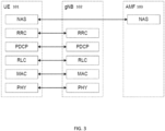
- user and control plane functions with monolithic gNB are shown in FIGS. 1 , 2 and 3 .
- PHY physical
- MAC Medium Access Control
- RLC Radio Link Control
- PDCP Packet Data Convergence Protocol
- SDAP Service Data Adaptation Protocol
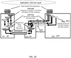
- the Protocol Data Unit (PDU) layer 9010 corresponds to the PDU carried between the user equipment (UE) 101 and the data network (DN) 9011 over the PDU session.
- PDU Protocol Data Unit
- UE 101 is connected to the 5G access network (AN) 902, which AN 902 is in turn connected via the N3 interface to the Intermediate UPF (I-UPF) 903a portion of the UPF 903, which I-UPF 903a is in turn connected via the N9 interface to the PDU session anchor 903b portion of the UPF 903, and which PDU session anchor 903b is connected to the DN 9011.
- the PDU session can correspond to Internet Protocol version 4 (IPv4), IPv6, or both types of IP packets (IPv4v6).
- IPv4 Internet Protocol version 4
- IPv6 IPv6
- GTP-U General Packet Radio Services Tunneling Protocol - User Plane
- RRC Radio Resource Control
- PDCP Packet Control
- RLC Packet Control
- MAC Packet Control
- PHY Packet Control sublayer
- NAS Non-Access Stratum
- NG-Radio Access Network (NG-RAN) architecture from 3GPP TS 38.401 is shown in FIGS. 4-5 .
- the NG-RAN consists of a set of gNBs connected to the 5GC through the NG interface.
- the NG-RAN 301 consists of a set of gNBs 302 connected to the 5GC 303 through the NG interface.
- Each gNB comprises gNB-CU 304 and one or more gNB-DU 305 (see FIG. 4 ).
- FIG. 4 NG-Radio Access Network
- E1 is the interface between gNB-CU-CP (CU-Control Plane) 304a and gNB-CU-UP (CU-User Plane) 304b
- F1-C is the interface between gNB-CU-CP 304a and gNB-DU 305
- F1-U is the interface between gNB-CU-UP 304b and gNB-DU 305.
- gNB 302 can consist of a gNB-CU-CP 304a, multiple gNB-CU-UPs (or gNB-CU-UP instances) 304b and multiple gNB-DUs (or gNB-DU instances) 305.
- One gNB-DU 305 is connected to only one gNB-CU-CP 304a, and one gNB-CU-UP 304b is connected to only one gNB-CU-CP 304a.
- L2 of 5G NR is split into the following sublayers (in accordance with 3GPP TS 38.300):
- FIG. 6 is a block diagram illustrating DL L2 structure (including a scheduler or priority handling module which handles multiple UEs in a cell), in accordance with 3GPP TS 38.300.
- FIG. 7 is a block diagram illustrating L2 structure for a single UE, in accordance with 3GPP TS 38.300.
- FIG. 8 is a block diagram illustrating L2 data flow example, in accordance with 3GPP TS 38.300 (in FIG. 8 , H denotes headers or sub-headers).
- Open Radio Access Network is based on disaggregated components which are connected through open and standardized interfaces based on 3GPP NG-RAN.
- An overview of O-RAN with disaggregated RAN CU (Centralized Unit), DU (Distributed Unit), and RU (Radio Unit), near-real-time Radio Intelligent Controller (Near-RT-RIC) and non-real-time RIC is illustrated in FIG. 9 .
- the CU (shown split as O-CU-CP 801a and O-CU-UP 801b) and the DU (shown as O-DU 802) are connected using the F1 interface (with F1-C for control plane and F1-U for user plane traffic) over a mid-haul (MH) path.
- One DU can host multiple cells (e.g., one DU could host 24 cells) and each cell may support many users. For example, one cell may support 800 Radio Resource Control (RRC)-connected users and out of these 800, there may be 250 Active users (i.e., users that have data to send at a given point of time).
- RRC Radio Resource Control
- a cell site can comprise multiple sectors, and each sector can support multiple cells.
- one site could comprise three sectors and each sector could support eight cells (with eight cells in each sector on different frequency bands).
- One CU-CP (CU-Control Plane) could support multiple DUs and thus multiple cells.
- a CU-CP could support 1,000 cells and around 100,000 User Equipments (UEs).
- Each UE could support multiple Data Radio Bearers (DRBs) and there could be multiple instances of CU-UP (CU-User Plane) to serve these DRBs.
- DRBs Data Radio Bearers
- CU-UP CU-User Plane
- each UE could support 4 DRBs, and 400,000 DRBs (corresponding to 100,000 UEs) may be served by five CU-UP instances (and one CU-CP instance).
- the DU could be located in a private data center, or it could be located at a cell-site.
- the CU could also be in a private data center or even hosted on a public cloud system.
- the DU and CU which are typically located at different physical locations, could be tens of kilometers apart.
- the CU communicates with a 5G core system, which could also be hosted in the same public cloud system (or could be hosted by a different cloud provider).
- a RU (Radio Unit) (shown as O-RU 803 in FIG. 9 ) is located at a cell-site and communicates with the DU via a front-haul (FH) interface.
- FH front-haul
- the E2 nodes (CU and DU) are connected to the near-real-time RIC 132 using the E2 interface.
- the E2 interface is used to send data (e.g., user and/or cell KPMs) from the RAN, and deploy control actions and policies to the RAN at near-real-time RIC 132.
- the applications or services at the near-real-time RIC 132 that deploys the control actions and policies to the RAN are called xApps.
- the E2 node advertises the metrics it can expose, and an xApp in the near-RT RIC can send a subscription message specifying key performance metrics which are of interest.
- the near-real-time RIC 132 is connected to the non-real-time RIC 133 (which is shown as part of Service Management and Orchestration (SMO) Framework 805 in FIG. 9 ) using the A1 interface.
- the applications that are hosted at non-RT-RIC are called rApps.
- O-eNB 806 which is shown as being connected to the near-real-time RIC 132 and the SMO Framework 805
- O-Cloud 804 which is shown as being connected to the SMO Framework 805).
- PDU connectivity service is a service that provides exchange of PDUs between a UE and a data network identified by a Data Network Name (DNN).
- DNN Data Network Name
- the PDU Connecitivity service is supported via PDU sessions that are established upon request from the UE.
- the DNN defines the interface to a specific external data network.
- One or more QoS flows can be supported in a PDU session. All the packets belonging to a specific QoS flow have the same 5QI (5G QoS Identifier).
- a PDU session consists of the following: Data Radio Bearer which is between UE and CU in RAN; and an NG-U GTP tunnel which is between CU-UP and UPF (User Plane Function) in the core network.
- FIG. 10 illustrates an example PDU session (in accordance with 3GPP TS 23.501) consisting of multiple DRBs, where each DRB can consist of multiple QoS flows.
- PDU session 901 UE 101; access network (AN) 902; and UPF 903, which includes Packet Detection Rules (PDRs) 9031.
- PDRs Packet Detection Rules
- FIG. 11 in the context of multiple PDU sessions involving multiple DRBs and QoS Flow Identifiers (QFIs), which PDU sessions are implemented involving UE 101, gNodeB 102, UPF 903, and DNNs 9011a and 9011b
- FIG. 12 in the context of Radio Resource Management (RRM) (for connecting UE 101 to the network via RU 306) with a MAC Scheduler 1001):
- RRM Radio Resource Management
- FIG. 11 illustrates multiple PDU sessions involving multiple DRBs and QoS Flow Identifiers (QFIs).
- the first column represents the 5QI value.
- the second column lists the different resource types, i.e., as one of Non-GBR, GBR, Delay-critical GBR.
- the third column (“Default Priority Level”) represents the priority level Priority 5QI, for which the lower the value the higher the priority of the corresponding QoS flow.
- the fourth column represents the Packet Delay Budget (PDB), which defines an upper bound for the time that a packet may be delayed between the UE and the N6 termination point at the UPF.
- PDB Packet Delay Budget
- the fifth column represents the Packet Error Rate (PER).
- the sixth column represents the maximimum data burst volume for delay-critical GBR types.
- the seventh column represents averaging window for GBR, delay critical GBR types. Note that only a subset of 5QI values defined in 3GPP TS 23.501 are shown in Table 1 below.
- 5QI value 1 represents GBR resource type with the default priority value of 20, PDB of 100 ms, PER of 0.01, and averaging window of 2000ms. Conversational voice falls under this catogery.
- 5QI value 7 represents non-GBR resource type with the default priority value of 70, PDB of 100ms and PER of 0.001. Voice, video (live streaming), and interactive gaming fall under this catogery.
- Table 1 5QI Value Resource Type Default Priority Level Packet Delay Budget (NOTE 3) Packet Error Rate Default Maximum Data Burst Volume (NOTE 2) Default Averaging Window Example Services 1 GBR (NOTE 1) 20 100 ms (NOTE 11, NOTE 13) 10 -2 N/A 2000 ms Conversational Voice 2 40 150 ms (NOTE 11, NOTE 13) 10 -3 N/A 2000 ms Conversational Video (Live Streaming) 3 30 50 ms (NOTE 11, NOTE 13) 10 -3 N/A 2000 ms Real Time Gaming, V2X messages (see TS 23.287 [121]) Electricity distribution - medium voltage.
- Process automation monitoring 4 50 300 ms (NOTE 11, NOTE 13) 10 -6 N/A 2000 ms Non-Conversational Video (Buffered Streaming) 65 (NOTE 9, NOTE 12) 7 75 ms (NOTE 7, NOTE 8) 10 -2 N/A 2000 ms Mission Cntical user plane Push To Talk voice (e.g., MCPTT1 66 (NOTE 12) 20 100 ms (NOTE 10, NOTE 13) 10 -2 N/A 2000 ms Non-Mission-Cntical user plane Push To Talk voice 67 (NOTE 12) 15 100 ms (NOTE 10, NOTE 13) 10 -3 N/A 2000 ms Mission Critical Video user plane 75 (NOTE 14) 71 56 150 ms (NOTE 11, NOTE 13, NOTE 15) 10 -6 N/A 2000 ms "Live" Uplink Streaming (e.g.
- Non-GBR 10 100 ms NOTE 10 NOTE 13) 10 -6 N/A N/A IMS Signalling 6 60 300 ms (NOTE 10, NOTE 13) 10 -6 N/A N/A Video (Buffered Streaming) TCP-based (e.g., www, e-mail, chat, ftp, p2p file shanng, progressive video, etc.) 7 70 100 ms (NOTE 10, NOTE 13) 10 -3 N/A N/A Voice, Video (Live Streaming) Interactive Gaming
- FIG. 12 is a block diagram illustrating RRM with a MAC Scheduler. L2 methods
- a network slice is a logical network that provides specific network capabilities and network characteristics, supporting various service properties for network slice customers (e.g., as specified in 3GPP TS 28.500).
- a network slice divides a physical network infrastructure into multiple virtual networks, each with its own (dedicated or shared) resources and service level agreements.
- An S-NSSAI Single Network Slice Selection Assistance Information identifies a network slice in 5G systems.
- S-NSSAI is comprised of: i) a Slice/Service type (SST), which refers to the expected Network Slice behavior in terms of features and services; and ii) a Slice Differentiator (SD), which is optional information that complements the Slice/Service type(s) to differentiate amongst multiple Network Slices of the same Slice/Service type.
- SST Slice/Service type
- SD Slice Differentiator
- SST has an 8-bit field, and it may have standardized and/or non-standardized values between 0 and 255.
- the range of 0 to 127 corresponds to standardized SST range, and the range of 128 to 255 corresponds to operator specific range.
- 3GPP has standardized some SSTs, e.g., SSTs for eMBB (enhanced mobile broadband), URLLC (ultra-reliable low latency communication) and MIoT (Massive Internet of Things (IoT)) slices.
- SSTs for eMBB enhanced mobile broadband
- URLLC ultra-reliable low latency communication
- MIoT Massive Internet of Things
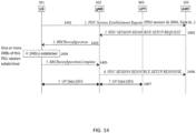
- UE first registers with a 5G cellular network identified by its PLMN ID (Public Land Mobile Network Identifier). UE knows which S-NSSAIs are allowed in a given registration area. It then establishes a PDU session associated with a given S-NSSAI in that network towards a target Data Network (DN), such as the internet. As in FIG. 11 , one or more QoS flows could be activated within this PDU session. UE can perform data transfer using a network slice for a given data network using that PDU session. A high-level view of UE establishing a PDU session with a specific DNN is shown in FIG. 14 .
- PLMN ID Public Land Mobile Network Identifier
- UE 101 sends a PDU Session Establishment Request (as referenced by process arrow 1401) to Access Mobility Function (AMF) 103, which PDU Session Establishment Request can include, e.g., PDU session ID, Data Network Name (DNN) and Slice ID.
- AMF Access Mobility Function
- the AMF 103 sends a PDU Session Resource Setup Request (as referenced by process arrow 1402) to gNB 102.
- the gNB 102 sends a RRC Reconfiguration message (as referenced by process arrow 1403) to UE 101.
- DRB(s) of the PDU session are established (as referenced by 1404).
- UE 101 sends a RRC Reconfiguration Complete message (as referenced by process arrow 1405) to gNB 102.
- gNB 102 sends a PDU Session Resource Setup Response (as referenced by process arrow 1406) to AMF 103.
- UP data e.g., including QFI
- UPF 903 UPF 903
- an NSSAI is a collection of S-NSSAIs.
- An NSSAI may be a Configured NSSAI, a Requested NSSAI or an Allowed NSSAI. There can be at most eight S-NSSAIs in Allowed and Requested NSSAIs sent in signaling messages between the UE and the Network.
- the Requested NSSAI signaled by the UE to the network allows the network to select the Serving AMF, Network Slice(s) and Network Slice Instance(s) for this UE.
- Network Slice Instance (NSI) consists of set of network function instances and the required resources that are deployed to serve the traffic associated with one or more S-NSSAIs.
- 3GPP TS 28.541 includes information model definitions, referred to as Network Resource Model (NRM), for the characterization of network slices.
- NEM Network Resource Model
- Management representation of a network slice is realized with Information Object Classes (IOCs), named NetworkSlice and NetworkSliceSubnet, as specified in 5G Network Resource Model (NRM), 3GPP TS 28.541.
- the NetworkSlice IOC and the NetworkSliceSubnet IOC represent the properties of a Network Slice Instance (NSI) and a Network Slice Subnet Instance (NSSI), respectively.
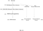
- FIG. 15 which illustrates a high-level, hierarchical view of network slice management, the slice management is subject to slice service level agreement (SLA) 1501.
- SLA slice service level agreement
- each NSI 1502 can be composed of a single NSSI (e.g., RAN NSSI 1503a) or multiple NSSIs (e.g., RAN NSSI 1503a, 5G Core NSSI 1503b and Transport Network NSSI 1503c).
- RRM policy managed entity 1504 is subject to RAN NSSI 1503a
- RAN domain 1505a is subject to RRM policy managed entity 1504
- 5G Core Network domain 1505b is subject to 5G Core NSSI 1503b
- Transport Network domain 1505c is subject to Transport Network NSSI 1503c.
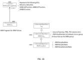
- FIG. 16 provides a simplified view of the classes and attributes of 5G Network Resource Model (NRM) for resource allocation to slices, which classes and attributes are explained below (the left side of FIG. 16 illustrates an NRM fragment for RRM policies; and the right side of FIG. 16 illustrates different IOCs).
- NRM Network Resource Model
- rRMPolicyDedicatedRatio 1701 shown in FIG. 17 defines the dedicated resource usage quota for the rRMPolicyMemberList, including dedicated resources.
- the sum of the rRMPolicyDedicatedRatio 1701 values assigned to all RRMPolicyRatio(s) name-contained by the same Managed Entity shall be less or equal to 100.
- Dedicated resources refer to the resources which are dedicated for use by the associated rRMPolicyMemberList. These resources cannot be shared even if the associated rRMPolicyMember does not use them.
- the Dedicated resources quota is represented by rRMPolicyDedicatedRatio 1701.
- rRMPolicyMinRatio 1702 shown in FIG. 17 defines the minimum resource usage quota for the associated rRMPolicyMemberList, including at least one of prioritized resources and dedicated resources, i.e., rRMPolicyMinRatio 1702 defines the resources quota that needs to be guaranteed for use by the associated rRMPolicyMemberList.
- rRMPolicyMinRatio 1702 defines the resources quota that needs to be guaranteed for use by the associated rRMPolicyMemberList.
- the sum of the rRMPolicyMinRatio 1702 values assigned to all RRMPolicyRatio(s) name-contained by same Managed Entity shall be less or equal 100.
- Prioritized resources refer to the resources which are preferentially used by the associated rRMPolicyMemberList.
- These resources are guaranteed for use by the associated rRMPolicyMemberList when it needs to use them. When not used, these resources may be used by other rRMPolicyMemberList(s) (i.e., the rRMPolicyMemberList(s) defined in RRMPolicyRatio(s) name-contained by the same Managed Entity).
- the prioritized resources quota is represented by [ rRMPolicyMinRatio minus rRMPolicyDedicatedRatio ] .
- the attribute rRMPolicyMaxRatio 1703 shown in FIG. 17 defines the maximum resource usage quota for the associated rRMPolicyMemberList, including at least one of shared resources, prioritized resources and dedicated resources. For the same resource type, the sum of the rRMPolicyMaxRatio values assigned to all RRMPolicyRatio(s) name-contained by the same Managed Entity can be greater than 100.
- Shared resources refer to the resources that are shared with other rRMPolicyMemberList(s) (i.e., the rRMPolicyMemberList(s) defined in RRMPolicyRatio(s) name-contained by the same Managed Entity). The shared resources are not guaranteed for use by the associated rRMPolicyMemberList.
- the shared resources quota is represented by [ rRMPolicyMaxRatio minus rRMPolicyMinRatio ] .
- dedicated pool of RBs is 5%, and prioritized pool of RBs is 10%.
- dedicated pool of RBs is 8%, and prioritized pool of RBs is 12% in the example above.
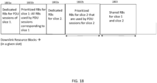
- FIG. 18 illustrates another example of resource allocation for DL resource blocks, involving two slices in a cell.
- each slice uses all of the respective dedicated RBs (e.g., 1801a for slice 1, and 1802a for slice 2), and each slice uses its share of prioritized RBs (e.g., 1801b for slice 1, and 1802b for slice 2).
- the remaining RBs could be used by the other slice(s).
- per-logical channel (or per-DRB) radio resource management (RRM) method was previously described above, e.g., in connection with FIG. 12 .
- constraints due to slicing radio resource parameters (such as dedicated, prioritized or shared resources) were previously explained above.
- Each DRB has its own QoS requirements (such as based on its 5QI), while each slice (which consists of PDU sessions and thus DRBs from several UEs in a cell) has its own SLA (e.g., aggregate throughput, etc.).
- Per-DRB RRM methods do not consider slice-related constraints and SLAs.
- Each UE may have multiple PDU session, each of which may belong to a different slice and possibly to a different RRM Policy Instance.
- different PDU sessions of the same UE may be assigned different resource (PRBs) quota by the RRM Policy framework.
- An RRM Policy Instance "n" may have more than one entry (i.e., slice S-NSSAI) in its member list L_n. Then the values of rRMPolicyDedicatedRatio X_n, rRMPolicyMinRatio Y_n and rRMPolicyMaxRatio Z_n are collectively applicable to all of these member slices together. For example, all slices in L_n shall have an aggregate of X_n % of available DU resources in the cell reserved as dedicated resources, and so on.
- network includes both networks and internetworks of all kinds, including the Internet, and is not limited to any particular type of network or inter-network.
- first and second are used to distinguish one element, set, data, object or thing from another, and are not used to designate relative position or arrangement in time.
- Coupled means a relationship between or among two or more devices, apparatus, files, programs, applications, media, components, networks, systems, subsystems, and/or means, constituting any one or more of (a) a connection, whether direct or through one or more other devices, apparatus, files, programs, applications, media, components, networks, systems, subsystems, or means, (b) a communications relationship, whether direct or through one or more other devices, apparatus, files, programs, applications, media, components, networks, systems, subsystems, or means, and/or (c) a functional relationship in which the operation of any one or more devices, apparatus, files, programs, applications, media, components, networks, systems, subsystems, or means depends, in whole or in part, on the operation of any one or more others thereof.
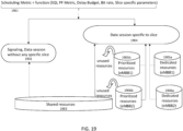
- FIG. 19 is a block diagram illustrating an example method for optimizing radio resource allocation for SG-slicing environment.
- the scheduling metric 1901 used for allocating resources is determined as a function of SQI, proportional-fair (PF) metric, packet delay budget, bit rate, and slice-specific parameters.
- shared resources 1903 are utilized for signaling and data session(s) without any specific slice (as referenced by 1902).
- PF proportional-fair
- Each UE may have multiple PDU sessions, each of which may belong to a different slice and possibly to a different RRM Policy Instance.
- different PDU sessions of the same UE may be assigned different resource (PRBs) quotas by the RRM Policy framework.
- An RRM Policy Instance "n" may have more than one entry (i.e., slice S-NSSAI) in its member list L_n.
- rRMPolicyDedicatedRatio X_n rRMPolicyMinRatio Y_n
- rRMPolicyMaxRatio Z_n are collectively applicable to all of these member slices together, e.g., all slices in L_n shall have an aggregate of X_n % of available DU resources in the cell reserved as dedicated resources, and so on.
- slice-aware downlink (DL) scheduling will be discussed.
- the total number of resources available for PDSCH transmission in a slot is referenced as Avail_RBTOT, and the RRM Policy ratio will be applied on these total available resources Avail RBTOT in DL.
- High priority traffic e.g., SRBs and MAC-CEs
- SRBs and MAC-CEs cannot belong to any slice according to current 3GPP data model, as these types of traffic are not PDU sessions.
- these traffic types are treated to be covered by the default RRM Policy Instance with only shared resources available, then the shared resources available will have to be proportionately divided amongst all RRM policy instances, which may result in fragmentation and delay of high priority SRB & MAC-CE transmissions, thereby leading to drop in system performance.
- nsSrbPolicy with a single entry (SRB slice) in its member list L n with S-NSSAI set to nsSrbSnssai.
- nsSrbPolicy and nsSrbSnssai are configuration parameters that can be set by the network operator.
- This SRB slice shall contain all SRB and MAC-CE traffic in the cell.
- this SRB slice shall not have a slice level SLA that is end-to-end, but rather shall be valid and applicable only within each cell in the DU.
- the distinct S-NSSAI for SRB traffic shall be useful for bookkeeping purposes for the network operator and can even be monetized.
- the SRB and MAC-CE traffic are of the highest priority and are scheduled prior to any other traffic in each slot. This includes both initial transmission and retransmission.
- the RRM Policy ratio shall be applied to total available resources AvailRB_TOT after allocating resources to high priority queues (as explained in the above section and as explained below).
- the retransmission TBs shall be scheduled after SRB & MAC CEs. Each retransmission TB shall only be transmitted without fragmentation. These shall be allocated resources from the corresponding slices to which the multiplexed MAC SDUs belong in proportion to their size. As an example, let's consider a retransmission TB with B information bytes (excluding padding bytes, if any) that required P PRBs for its initial transmission.
- the scheduler shall allocate (b_k/B)*P PRBs from policy instance k, where b_k is the total size in bytes of all SDUs in member list L_k. Note that there may be multiple SDUs belonging to one or more slices in member list L_k that are governed by this single policy instance #k. The padding bytes are ignored in this calculation.
- all resources required for transmission of each SRB, MAC CE and MAC SDUs that are multiplexed within a retransmission TB must be available from the respective slices to which each such SRB, MAC CE & MAC SDU belongs, for the retransmission TB to be scheduled in a slot.
- a vendor specific data model can be used and it is not necessary to use 3GPP specific data model described earlier.
- retransmission TBs may be allocated RBs from different slices, it shall not be associated with any specific slice and shall remain an independent Queue.
- the DL scheduler shall derive a logical channel (LC) scheduling metric ⁇ based on the UE's proportional fair metric and the LC 5QI priority, along with the packet delay budget (PDB) and guaranteed flow bitrate (GFBR), in order to meet the QoS characteristics of the 5QI QoS flow and achieve fairness across different UEs in the cell.
- LC logical channel
- PDB packet delay budget
- GFBR guaranteed flow bitrate
- SQI-aware downlink scheduler uses the QoS characteristics of each LC that is defined by its associated 5QI priority value to determine a scheduling metric that allows scheduling on a per LC basis.
- a scheduling metric that allows scheduling on a per LC basis.
- the slice priority value can be derived based on slice level requirements or SLA, e.g., per-slice aggregate throughput, target PER, maximum latency, user throughput, etc.
- the slice SLA dictates whether nsPriority is dependent on the LC, PDU session, UE or the slice. For example, if the slice SLA indicates that the aggregate throughput of a slice is to be limited to T Mbps, then the slice priority metric nsPriority will be the same for all LCs that belong to a particular slice.
- nsPriority will be specific to a PDU session, i.e., it will be the same for all LCs within a PDU session, but will be different for LCs across different PDU sessions, even if they belong to the same slice.
- the slice SLA is aggregate throughput achieved in the slice across all PDU sessions admitted in the slice.
- the slice specific priority metric K s *R rem /R target where the following conditions apply:
- nsPriority is [0, K s ] where K s is a weight common to all slices; and W is the averaging window, and can be set to 2000ms (same as that of GBR 5QI flows).
- Method to allocate resources According to an example embodiment of a method, the following steps are implemented to allocate resources for shortlisted logical channels (LCs):
- value of ⁇ n is equal to (old) value of RB n,prio if (old) value of RB share is equal to zero (i.e., all shared resources were used in the previous slot). Remaining prioritized resources from the previous slot are added as part of shared resources for the next slot. This also happens if (old) value of RB n,prio is less than or equal to max(0, AvailRB TOT - RB share ).
- Uplink Slice-Aware Scheduling In the following sections, details of uplink slice-aware scheduling will be discussed.
- Retransmission Transport Blocks TBs
- AvailRB TOT AvailRB TOT ⁇ AllocRB
- AllocRB is the total RBs allocated for transmission of high priority LCGs/retransmissions.
- Uplink Scheduling based on RRM Policy Ratio in the DU Regarding scheduling and resource allocation for SR, i) the scheduling of SR happens with priority higher than BSR, and ii) if QCI 1 bearer (VoNR) is present, then the allocation size is as per GBR.
- QCI 1 bearer VoNR
- the UL scheduler shall derive a Logical Channel Group (LCG) scheduling metric based on 5QI priority, guaranteed flow bitrate (GFBR), and proportional fair (PF) metric in order to meet the QoS characteristics of the 5QI QoS flow.
- LCG Logical Channel Group
- GFBR guaranteed flow bitrate
- PF proportional fair
- Each LCG can consist of one or more LCs with different QoS classes (i.e., different SQIs).
- the LCG priority, P LCG is computed using the LC which has the most stringent QoS requirements in that group of LCs in the LCG.
- P LCG P LC + P GBR + P PF
- This 5QI-aware uplink scheduler uses the QoS characteristics of each LCG that is defined by its associated maximum 5QI priority value among all LCs in the LCG to determine a scheduling metric that allows scheduling on a per LCG basis.
- the variables P LCG (LCG priority), P LC (logical channel priority) P GBR (guaranteed bitrate priority) and P PF (achievable data rate priority) will be explained in detail below.
- Logical channel priority P LC As discussed earlier, for each LCG, LC with the most stringent 5QI is chosen for the P LC calculation below:
- slice awareness by utilizing this SQI-aware scheduler as the basic building block and adding slice awareness on top of it in order to meet the slice SLA. This is achieved by dynamically allocating resources to meet the SLA of each slice by modifying the 5QI scheduling metric to include the slice level priority as detailed below.
- the slice priority value is derived based on slice level requirements or SLA, e.g., per-slice aggregate throughput, target PER, maximum latency, user throughput, etc.
- the slice SLA is aggregate throughput achieved in the slice across all PDU sessions admitted in the slice.
- Step 2.1 Re-select logical channel LCG n,m in the order of scheduling priority metric that were either: allocated dedicated an/or prioritized resources from policy instance 'n' in Round 1, or not allocated any resources due to lack of both dedicated & prioritized resources available in policy instance 'n'.
- This approach helps to ensure that we continue to use a SQI-aware PF scheduler to determine the order in which logical channels are selected for scheduling, as network slicing does not explicitly mandate a change in the priority of logical channels.
- the RRM Policy Ratio rules are enforced, but not on a per-slot basis, but instead on an average over a pre-set averaging window W.
Landscapes
- Engineering & Computer Science (AREA)
- Computer Networks & Wireless Communication (AREA)
- Signal Processing (AREA)
- Mobile Radio Communication Systems (AREA)
Applications Claiming Priority (2)
| Application Number | Priority Date | Filing Date | Title |
|---|---|---|---|
| IN202321055298 | 2023-08-17 | ||
| US18/802,205 US20250063387A1 (en) | 2023-08-17 | 2024-08-13 | Optimized radio resource management for 5g network slicing |
Publications (2)
| Publication Number | Publication Date |
|---|---|
| EP4510751A1 true EP4510751A1 (de) | 2025-02-19 |
| EP4510751B1 EP4510751B1 (de) | 2026-04-15 |
Family
ID=92458053
Family Applications (1)
| Application Number | Title | Priority Date | Filing Date |
|---|---|---|---|
| EP24194891.8A Active EP4510751B1 (de) | 2023-08-17 | 2024-08-16 | Optimierte funkressourcenverwaltung für 5g-netzwerk-slicing |
Country Status (1)
| Country | Link |
|---|---|
| EP (1) | EP4510751B1 (de) |
-
2024
- 2024-08-16 EP EP24194891.8A patent/EP4510751B1/de active Active
Non-Patent Citations (1)
| Title |
|---|
| "3rd Generation Partnership Project; Technical Specification Group Services and System Aspects; Management and orchestration; 5G Network Resource Model (NRM); Stage 2 and stage 3 (Release 18 )", 26 June 2023 (2023-06-26), XP052511804, Retrieved from the Internet <URL:https://ftp.3gpp.org/tsg_sa/WG5_TM/TSGS5_149/SA_100/28541-i40.zip 28541-i40_c04_c07.docx> [retrieved on 20230626] * |
Also Published As
| Publication number | Publication date |
|---|---|
| EP4510751B1 (de) | 2026-04-15 |
Similar Documents
| Publication | Publication Date | Title |
|---|---|---|
| US11284288B2 (en) | Method and apparatus for microslicing wireless communication networks with device groups, service level objectives, and load/admission control | |
| US11240724B2 (en) | Method and device for handover | |
| CN101124844B (zh) | 用于上行链路传送的保证位速率通信量的支持 | |
| KR101059876B1 (ko) | 이동통신 시스템의 서비스 품질 보장을 위한 데이터전송량 선택 방법 | |
| US20250063388A1 (en) | Policy-based performance management for 5g network slices in o-ran networks | |
| US20250088464A1 (en) | System and methods for network slicing for coexistence of low latency, low loss and scalable throughput (l4s) and non-l4s traffic in wireless networks | |
| US20240314628A1 (en) | Optimizations for overload control in o-ran networks | |
| US20250063387A1 (en) | Optimized radio resource management for 5g network slicing | |
| EP4510520A1 (de) | Richtlinienbasierte leistungsverwaltung für 5g-netzwerk-slices in o-ran-netzwerken | |
| US20250063451A1 (en) | Load balancing optimizations for o-ran networks | |
| EP4554324A1 (de) | Optimierte funkressourcenverwaltung unter verwendung von maschinenlernansätzen in o-ran-netzwerken | |
| EP4432725A1 (de) | Optimierungen zur überlastregelung in o-ran-netzwerken | |
| EP4598102A1 (de) | Maschinenlernunterstützte funkressourcenverwaltungsrichtlinien für niedrige datenratenlatenz und andere anwendungen in o-ran-netzwerken | |
| EP4510751B1 (de) | Optimierte funkressourcenverwaltung für 5g-netzwerk-slicing | |
| EP4648463A1 (de) | Optimierung der funkressourcenverwaltung in o-ran-netzwerken unter verwendung von maschinenlerntechniken | |
| EP4521815A1 (de) | System und verfahren zum netzwerk-slicing zur koexistenz von niedriglatentem, verlustarmem und skalierbarem durchsatz (l4s) und nicht-l4s-verkehr in drahtlosen netzwerken | |
| US20250365749A1 (en) | Optimizing radio resource management in o-ran networks using machine learning techniques | |
| EP4418718A1 (de) | Richtlinienbasierte leistungsverwaltung für hochskalierbare o-ran-netzwerke | |
| EP4513956A1 (de) | Lastausgleichsoptimierungen für o-ran-netzwerke | |
| EP4507372B1 (de) | Cu-du-flusssteuerungsoptimierungen für verlustbehaftetes midhaul in o-ran-netzwerken | |
| US20240284441A1 (en) | Policy based performance management for highly scalable o-ran networks | |
| US20250055795A1 (en) | Cu-du flow control optimizations for lossy midhaul in o-ran networks | |
| EP4475592A1 (de) | Verfahren zur koexistenz von l4s- und nicht-l4s-verkehr mit niedriger latenz, geringem verlust und skalierbarem durchsatz in 5g-netzwerken | |
| US20250150897A1 (en) | Optimized radio resource management using machine learning approaches in o-ran networks | |
| EP4529272A1 (de) | Optimierte verwaltung von bandbreitenteilen für mobilfunknetze |
Legal Events
| Date | Code | Title | Description |
|---|---|---|---|
| PUAI | Public reference made under article 153(3) epc to a published international application that has entered the european phase |
Free format text: ORIGINAL CODE: 0009012 |
|
| STAA | Information on the status of an ep patent application or granted ep patent |
Free format text: STATUS: REQUEST FOR EXAMINATION WAS MADE |
|
| 17P | Request for examination filed |
Effective date: 20240816 |
|
| AK | Designated contracting states |
Kind code of ref document: A1 Designated state(s): AL AT BE BG CH CY CZ DE DK EE ES FI FR GB GR HR HU IE IS IT LI LT LU LV MC ME MK MT NL NO PL PT RO RS SE SI SK SM TR |
|
| GRAP | Despatch of communication of intention to grant a patent |
Free format text: ORIGINAL CODE: EPIDOSNIGR1 |
|
| STAA | Information on the status of an ep patent application or granted ep patent |
Free format text: STATUS: GRANT OF PATENT IS INTENDED |
|
| INTG | Intention to grant announced |
Effective date: 20251111 |
|
| GRAS | Grant fee paid |
Free format text: ORIGINAL CODE: EPIDOSNIGR3 |
|
| P01 | Opt-out of the competence of the unified patent court (upc) registered |
Free format text: CASE NUMBER: UPC_APP_0003992_4510751/2026 Effective date: 20260203 |
|
| GRAA | (expected) grant |
Free format text: ORIGINAL CODE: 0009210 |
|
| STAA | Information on the status of an ep patent application or granted ep patent |
Free format text: STATUS: THE PATENT HAS BEEN GRANTED |
|
| AK | Designated contracting states |
Kind code of ref document: B1 Designated state(s): AL AT BE BG CH CY CZ DE DK EE ES FI FR GB GR HR HU IE IS IT LI LT LU LV MC ME MK MT NL NO PL PT RO RS SE SI SK SM TR |
|
| REG | Reference to a national code |
Ref country code: CH Ref legal event code: F10 Free format text: ST27 STATUS EVENT CODE: U-0-0-F10-F00 (AS PROVIDED BY THE NATIONAL OFFICE) Effective date: 20260415 |