EP4510314A1 - Battery cell with improved sealing - Google Patents
Battery cell with improved sealing Download PDFInfo
- Publication number
- EP4510314A1 EP4510314A1 EP23306394.0A EP23306394A EP4510314A1 EP 4510314 A1 EP4510314 A1 EP 4510314A1 EP 23306394 A EP23306394 A EP 23306394A EP 4510314 A1 EP4510314 A1 EP 4510314A1
- Authority
- EP
- European Patent Office
- Prior art keywords
- plug
- battery cell
- cavity
- insertion element
- hole
- Prior art date
- Legal status (The legal status is an assumption and is not a legal conclusion. Google has not performed a legal analysis and makes no representation as to the accuracy of the status listed.)
- Pending
Links
Images



Classifications
-
- H—ELECTRICITY
- H01—ELECTRIC ELEMENTS
- H01M—PROCESSES OR MEANS, e.g. BATTERIES, FOR THE DIRECT CONVERSION OF CHEMICAL ENERGY INTO ELECTRICAL ENERGY
- H01M50/00—Constructional details or processes of manufacture of the non-active parts of electrochemical cells other than fuel cells, e.g. hybrid cells
- H01M50/60—Arrangements or processes for filling or topping-up with liquids; Arrangements or processes for draining liquids from casings
- H01M50/609—Arrangements or processes for filling with liquid, e.g. electrolytes
- H01M50/627—Filling ports
- H01M50/636—Closing or sealing filling ports, e.g. using lids
- H01M50/645—Plugs
-
- H—ELECTRICITY
- H01—ELECTRIC ELEMENTS
- H01M—PROCESSES OR MEANS, e.g. BATTERIES, FOR THE DIRECT CONVERSION OF CHEMICAL ENERGY INTO ELECTRICAL ENERGY
- H01M50/00—Constructional details or processes of manufacture of the non-active parts of electrochemical cells other than fuel cells, e.g. hybrid cells
- H01M50/10—Primary casings; Jackets or wrappings
- H01M50/102—Primary casings; Jackets or wrappings characterised by their shape or physical structure
- H01M50/103—Primary casings; Jackets or wrappings characterised by their shape or physical structure prismatic or rectangular
-
- H—ELECTRICITY
- H01—ELECTRIC ELEMENTS
- H01M—PROCESSES OR MEANS, e.g. BATTERIES, FOR THE DIRECT CONVERSION OF CHEMICAL ENERGY INTO ELECTRICAL ENERGY
- H01M50/00—Constructional details or processes of manufacture of the non-active parts of electrochemical cells other than fuel cells, e.g. hybrid cells
- H01M50/60—Arrangements or processes for filling or topping-up with liquids; Arrangements or processes for draining liquids from casings
- H01M50/609—Arrangements or processes for filling with liquid, e.g. electrolytes
- H01M50/627—Filling ports
- H01M50/636—Closing or sealing filling ports, e.g. using lids
-
- H—ELECTRICITY
- H01—ELECTRIC ELEMENTS
- H01M—PROCESSES OR MEANS, e.g. BATTERIES, FOR THE DIRECT CONVERSION OF CHEMICAL ENERGY INTO ELECTRICAL ENERGY
- H01M50/00—Constructional details or processes of manufacture of the non-active parts of electrochemical cells other than fuel cells, e.g. hybrid cells
- H01M50/10—Primary casings; Jackets or wrappings
- H01M50/147—Lids or covers
- H01M50/148—Lids or covers characterised by their shape
- H01M50/15—Lids or covers characterised by their shape for prismatic or rectangular cells
-
- Y—GENERAL TAGGING OF NEW TECHNOLOGICAL DEVELOPMENTS; GENERAL TAGGING OF CROSS-SECTIONAL TECHNOLOGIES SPANNING OVER SEVERAL SECTIONS OF THE IPC; TECHNICAL SUBJECTS COVERED BY FORMER USPC CROSS-REFERENCE ART COLLECTIONS [XRACs] AND DIGESTS
- Y02—TECHNOLOGIES OR APPLICATIONS FOR MITIGATION OR ADAPTATION AGAINST CLIMATE CHANGE
- Y02E—REDUCTION OF GREENHOUSE GAS [GHG] EMISSIONS, RELATED TO ENERGY GENERATION, TRANSMISSION OR DISTRIBUTION
- Y02E60/00—Enabling technologies; Technologies with a potential or indirect contribution to GHG emissions mitigation
- Y02E60/10—Energy storage using batteries
Definitions
- the present invention relates to a rechargeable battery cell, in particular a prismatic battery cell.
- a battery cell from prior art comprising a casing housing electrode stack(s) and other parts/components for electrical and mechanical functions, and a top cover assembly with a top plate having an electrolyte filling hole, in which a plug is inserted for closing.
- the electrolyte filling hole is used for filling the casing with a liquid electrolyte then it is closed by inserting the plug with mechanical force.
- the invention is intended to solve this drawback, by providing a battery with an improved sealing element.
- the invention relates to a battery cell comprising a casing housing electrode stack(s), and a top cover assembly comprising a top plate having an electrolyte filling hole on it, and the battery cell comprising a plug for closing the electrolyte filling hole, characterized in that the plug is made of an elastically deformable material, the plug comprising a central cavity, and in that the battery cell comprises an insertion element intended to be inserted in force in the cavity so that the plug expands radially in the filing hole.
- the plug of the invention does not need to be inserted in force in the electrolyte filing hole, but it is smoothly inserted in the hole before being radially expanded by the insertion element, so that the plug is firmly fixed in the hole. This fixation does not produce scratches and/or damages on the surface of the plug.
- a battery cell according to the invention may comprise any of the following features, taken alone or in any possible combination.
- Figure 1 shows a battery cell 10 according to a first embodiment of the invention.
- the battery cell 10 comprises a casing 12, for instance a metallic can.
- the casing 12 classically houses electrode stack(s) 13.
- a top cover assembly, including a top plate 14 in it, is provided to close the casing 12.
- the top cover assembly comprises terminals 16 electrically connected to the electrode stack(s) 13.
- the casing 12 comprises a filling hole 18, used for filling the casing 12 with a liquid electrolyte 19.
- the filling hole 18 is arranged in the top plate 14.
- the battery cell 10 comprises a plug 20, shown on Figure 2 , intended to be inserted in the filling hole 18, as shown on Figure 3 .
- the plug 20 has a body 21 having a revolution shape around a central axis X.
- the plug 20 is made of an elastically deformable material, preferentially with the properties of:
- the plug 20 comprises a cavity 22, preferentially cylindrical, extending in the body 21 along the central axis X.
- the cavity 22 has a mouth on a proximal side of the plug 20, and is closed at a distal side of the plug 20.
- the edges of the mouth are preferentially chamfered or rounded.
- the body 21 is thinner at the distal side, in order to facilitate its insertion into the filling hole 18.
- the body 21 has a partial conic shape.
- the plug 20 comprises a flange 24 extending radially toward the exterior and surrounding the mouth of the cavity 22.
- the body 21 has a plug diameter that is slightly smaller than a hole diameter of the filling hole 18. So, the plug 20 can be inserted easily in the filling hole 18, without friction resistance.
- the flange 24 is intended to come in abutment against an edge area of the filling hole 18, in order to limit the displacement of the plug 20 in the filling hole 18.
- the battery cell 10 comprises an insertion element 26 intended to be inserted in force in the cavity 22.
- the cavity 22 receives the insertion element 26, it expands radially so that the plug diameter locally becomes higher than the hole diameter (or equal when this expansion is limited/compressed by the filling hole 18 itself).
- the insertion element 26 is inserted in the cavity 22 when the body 21 is in the filling hole 18, so that the plug 20 expands radially in the filing hole 18.
- the battery cell 10 also comprises a sealing cap 28 covering the plug 20, welded to the top plate 14.
- the sealing cap 28 has for example a shape of a disc.
- the top plate 14 comprises a recess 30 surrounding the edge of the filling hole 18, intended to receive the sealing cap 28.
- the recess 30 preferentially has similar dimensions as the sealing cap 28, or slightly larger dimensions than the dimensions of the sealing cap 28, so that the sealing cap 28 is stably positioned in its axial and radial directions for the subsequent welding process.
- the recess diameter is for example 0.2 mm larger than the cap diameter.
- the insertion element 26 is a pin, having a diameter that is superior to the diameter of the cavity 22.
- the pin is chamfered or rounded at its distal end in order to facilitate its insertion in the cavity 22.
- the pin is made in one piece with the sealing cap 28, so the sealing cap 28 is assembled in the same step as the insertion element 26.
- a method of manufacturing the battery cell 10 will now be disclosed.
- the battery cell 10 is assembled in a classical manner.
- the electrode stack(s) 13 are wrapped in an insulation sock and inserted inside the casing 12. Tabs of the electrode stack(s) 13 are connected to collectors, and the top cover assembly is assembled with the casing 12. The collectors are connected to the terminals 16 of the top cover assembly.
- the top cover assembly is fixed to the casing 12 at the periphery of the top plate 14. This fixation is made hermetical, for instance by welding.
- the casing 12 is then filled with electrolyte 19 through the filling hole 18.
- Vacuum is then made in the casing 12, by means of a vacuum chamber in which the battery cell 10 is arranged.
- the filling hole 18 is closed temporarily by the plug 20.
- the plug 20 is inserted smoothly in the filling hole 18, until the flange 24 comes in abutment against the edge area of the filling hole 18.
- the insertion element 26 is then inserted in force into the cavity 22 in order to radially expand the plug 20 against a peripheral wall of the filling hole 18. This allows a firm/tight closing of the filling hole 18.
- the insertion element 26 is provided in the same time as the cap 28 that is interdependent with the insertion element 26.
- the cap 28 is inserted in the recess 30 while the insertion element 26 is inserted in the cavity 22.
- the insertion element 26 is provided separately from the cap 28, before the cap 28.
- the cap 28 is then welded to the top plate 14, in order to complete the hermetic closing.
- Figure 4 shows a second embodiment of the invention.
- the insertion element 26 is a ball, for example a steel ball, with a diameter superior to the diameter of the cavity 22. This ball is not in one piece with the cap 28, so it is assembled before the cap 28.
- the rest of the battery cell 10 is the same as in the first embodiment.
Landscapes
- Chemical & Material Sciences (AREA)
- Chemical Kinetics & Catalysis (AREA)
- Electrochemistry (AREA)
- General Chemical & Material Sciences (AREA)
- Sealing Battery Cases Or Jackets (AREA)
- Filling, Topping-Up Batteries (AREA)
Abstract
Description
- The present invention relates to a rechargeable battery cell, in particular a prismatic battery cell.
- A battery cell from prior art is already known, comprising a casing housing electrode stack(s) and other parts/components for electrical and mechanical functions, and a top cover assembly with a top plate having an electrolyte filling hole, in which a plug is inserted for closing. The electrolyte filling hole is used for filling the casing with a liquid electrolyte then it is closed by inserting the plug with mechanical force.
- It should be noticed that such an insertion with mechanical force may produce scratches and/or damages on the surface of the plug, which may lead to a failure of required sealing.
- The invention is intended to solve this drawback, by providing a battery with an improved sealing element.
- To this end, the invention relates to a battery cell comprising a casing housing electrode stack(s), and a top cover assembly comprising a top plate having an electrolyte filling hole on it, and the battery cell comprising a plug for closing the electrolyte filling hole, characterized in that the plug is made of an elastically deformable material, the plug comprising a central cavity, and in that the battery cell comprises an insertion element intended to be inserted in force in the cavity so that the plug expands radially in the filing hole.
- The plug of the invention does not need to be inserted in force in the electrolyte filing hole, but it is smoothly inserted in the hole before being radially expanded by the insertion element, so that the plug is firmly fixed in the hole. This fixation does not produce scratches and/or damages on the surface of the plug.
- A battery cell according to the invention may comprise any of the following features, taken alone or in any possible combination.
- The battery cell comprises a sealing cap covering the plug, the sealing cap being welded to the top plate.
- The insertion element is a pin.
- The insertion element is made in one piece with the sealing cap.
- The insertion element is a ball, for example a steel ball.
- The plug comprises a flange extending radially toward the exterior and surrounding a mouth of the cavity.
- The plug has a plug diameter and the filling hole has a hole diameter, the plug diameter being inferior to the hole diameter when the cavity is empty, and the plug diameter being locally superior to the hole diameter when the insertion element is in the cavit.
- Several aspects and advantages of the invention will be enlightened in the following disclosure, only given as a non-limitative example and made in reference to attached drawings, in which:
-
Figure 1 is a perspective view of a battery cell according to a first embodiment of the invention; -
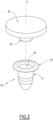
Figure 2 is a perspective view of a plug and a cap equipping the battery cell ofFigure 1 ; -
Figure 3 is a sectional view of the battery cell ofFigure 1 , transversal plane including the plug; -
Figure 4 is a detail of a plug of a battery cell according to a second embodiment of the invention. -
Figure 1 shows abattery cell 10 according to a first embodiment of the invention. - The
battery cell 10 comprises acasing 12, for instance a metallic can. Thecasing 12 classically houses electrode stack(s) 13. A top cover assembly, including atop plate 14 in it, is provided to close thecasing 12. - The top cover assembly comprises
terminals 16 electrically connected to the electrode stack(s) 13. - The
casing 12 comprises afilling hole 18, used for filling thecasing 12 with aliquid electrolyte 19. Preferentially, thefilling hole 18 is arranged in thetop plate 14. - In order to close the
filling hole 18 after electrolyte filling, thebattery cell 10 comprises aplug 20, shown onFigure 2 , intended to be inserted in thefilling hole 18, as shown onFigure 3 . - The
plug 20 has abody 21 having a revolution shape around a central axis X. - The
plug 20 is made of an elastically deformable material, preferentially with the properties of: - chemical compatibility with the electrolyte, i.e., no chemical reaction with the electrolyte;
- high elastic elongation, i.e., preferentially higher than 50%;
- significantly lower stiffness than the
top plate 14 and theinsertion element 26, i.e., preferentially smaller than one-tenth of those of thetop plate 14 and theinsertion element 26; - higher thermal resistance, i.e., preferentially, it should resist thermal shock exposed to 200 degrees Celsius for 5 seconds.
- The
plug 20 comprises acavity 22, preferentially cylindrical, extending in thebody 21 along the central axis X. Thecavity 22 has a mouth on a proximal side of theplug 20, and is closed at a distal side of theplug 20. The edges of the mouth are preferentially chamfered or rounded. - The
body 21 is thinner at the distal side, in order to facilitate its insertion into thefilling hole 18. For example, thebody 21 has a partial conic shape. - The
plug 20 comprises aflange 24 extending radially toward the exterior and surrounding the mouth of thecavity 22. - The
body 21 has a plug diameter that is slightly smaller than a hole diameter of thefilling hole 18. So, theplug 20 can be inserted easily in thefilling hole 18, without friction resistance. Theflange 24 is intended to come in abutment against an edge area of thefilling hole 18, in order to limit the displacement of theplug 20 in thefilling hole 18. - The
battery cell 10 comprises aninsertion element 26 intended to be inserted in force in thecavity 22. When thecavity 22 receives theinsertion element 26, it expands radially so that the plug diameter locally becomes higher than the hole diameter (or equal when this expansion is limited/compressed by thefilling hole 18 itself). - Thus, the
insertion element 26 is inserted in thecavity 22 when thebody 21 is in thefilling hole 18, so that theplug 20 expands radially in thefiling hole 18. - Preferentially, the
battery cell 10 also comprises a sealingcap 28 covering theplug 20, welded to thetop plate 14. The sealingcap 28 has for example a shape of a disc. - Preferentially, the
top plate 14 comprises arecess 30 surrounding the edge of thefilling hole 18, intended to receive the sealingcap 28. Therecess 30 preferentially has similar dimensions as the sealingcap 28, or slightly larger dimensions than the dimensions of thesealing cap 28, so that the sealingcap 28 is stably positioned in its axial and radial directions for the subsequent welding process. Considering the typical size of the cap and recess, the recess diameter is for example 0.2 mm larger than the cap diameter. - In the first embodiment, the
insertion element 26 is a pin, having a diameter that is superior to the diameter of thecavity 22. The pin is chamfered or rounded at its distal end in order to facilitate its insertion in thecavity 22. - Preferentially, the pin is made in one piece with the
sealing cap 28, so thesealing cap 28 is assembled in the same step as theinsertion element 26. - A method of manufacturing the
battery cell 10 will now be disclosed. - First, the
battery cell 10 is assembled in a classical manner. The electrode stack(s) 13 are wrapped in an insulation sock and inserted inside thecasing 12. Tabs of the electrode stack(s) 13 are connected to collectors, and the top cover assembly is assembled with thecasing 12. The collectors are connected to theterminals 16 of the top cover assembly. - The top cover assembly is fixed to the
casing 12 at the periphery of thetop plate 14. This fixation is made hermetical, for instance by welding. - The
casing 12 is then filled withelectrolyte 19 through thefilling hole 18. - Vacuum is then made in the
casing 12, by means of a vacuum chamber in which thebattery cell 10 is arranged. - In order to keep the vacuum in the
casing 12, thefilling hole 18 is closed temporarily by theplug 20. - To this end, the
plug 20 is inserted smoothly in thefilling hole 18, until theflange 24 comes in abutment against the edge area of thefilling hole 18. - The
insertion element 26 is then inserted in force into thecavity 22 in order to radially expand theplug 20 against a peripheral wall of the fillinghole 18. This allows a firm/tight closing of the fillinghole 18. - In the disclosed first embodiment, the
insertion element 26 is provided in the same time as thecap 28 that is interdependent with theinsertion element 26. Thecap 28 is inserted in therecess 30 while theinsertion element 26 is inserted in thecavity 22. - However, in other embodiments, as in the second embodiment that will be disclosed later, the
insertion element 26 is provided separately from thecap 28, before thecap 28. - The
cap 28 is then welded to thetop plate 14, in order to complete the hermetic closing. - It appears that the invention allows a reliable sealing of the filling
hole 18. -
Figure 4 shows a second embodiment of the invention. - In this second embodiment, the
insertion element 26 is a ball, for example a steel ball, with a diameter superior to the diameter of thecavity 22. This ball is not in one piece with thecap 28, so it is assembled before thecap 28. - The rest of the
battery cell 10 is the same as in the first embodiment. -
- 10 -
- Battery cell
- 12 -
- Casing / can
- 13 -
- Electrode stack(s)
- 14 -
- Top plate
- 16 -
- Terminals
- 18 -
- Filling hole
- 19 -
- Electrolyte
- 20 -
- Plug
- 21 -
- Plug body
- 22 -
- Cavity
- 24 -
- Flange
- 26 -
- Insertion element
- 28 -
- Sealing cap
- 30 -
- Recess
Claims (7)
- A battery cell (10) comprising a casing (12) housing electrode stack(s) (13), and a top cover assembly comprising a top plate (14) having an electrolyte filling hole (18) on it, and the battery cell (10) comprising a plug (20) for closing the electrolyte filling hole (18), characterized in that the plug (20) is made of an elastically deformable material, the plug (20) comprising a central cavity (22), and in that the battery cell (10) comprises an insertion element (26) intended to be inserted in force in the cavity (22) so that the plug (20) expands radially in the filing hole (18).
- The battery cell (10) of claim 1, comprising a sealing cap (28) covering the plug (20), the sealing cap (28) being welded to the top plate (14).
- The battery cell (10) of claim 2, wherein the insertion element (26) is a pin.
- The battery cell (10) of claim 3, wherein the insertion element (26) is made in one piece with the sealing cap (28).
- The battery cell (10) of claim 1 or 2, wherein the insertion element (26) is a ball, for example a steel ball.
- The battery cell (10) of any of the preceding claims, wherein the plug (20) comprises a flange (24) extending radially toward the exterior and surrounding a mouth of the cavity (22).
- The battery cell (10) of any of the preceding claims, wherein the plug (20) has a plug diameter and the filling hole (18) has a hole diameter, the plug diameter being inferior to the hole diameter when the cavity (22) is empty, and the plug diameter being locally superior to the hole diameter when the insertion element (26) is in the cavity (22).
Priority Applications (1)
| Application Number | Priority Date | Filing Date | Title |
|---|---|---|---|
| EP23306394.0A EP4510314A1 (en) | 2023-08-18 | 2023-08-18 | Battery cell with improved sealing |
Applications Claiming Priority (1)
| Application Number | Priority Date | Filing Date | Title |
|---|---|---|---|
| EP23306394.0A EP4510314A1 (en) | 2023-08-18 | 2023-08-18 | Battery cell with improved sealing |
Publications (1)
| Publication Number | Publication Date |
|---|---|
| EP4510314A1 true EP4510314A1 (en) | 2025-02-19 |
Family
ID=87889555
Family Applications (1)
| Application Number | Title | Priority Date | Filing Date |
|---|---|---|---|
| EP23306394.0A Pending EP4510314A1 (en) | 2023-08-18 | 2023-08-18 | Battery cell with improved sealing |
Country Status (1)
| Country | Link |
|---|---|
| EP (1) | EP4510314A1 (en) |
Citations (4)
| Publication number | Priority date | Publication date | Assignee | Title |
|---|---|---|---|---|
| WO2006133617A1 (en) * | 2005-06-17 | 2006-12-21 | Shenzhen Bak Battery Co., Ltd. | Cover plate assembly for lithium ion battery, battery case and battery using the same |
| US20110212360A1 (en) * | 2005-09-02 | 2011-09-01 | A123 Systems | Battery cell design and method of its construction |
| WO2014068641A1 (en) * | 2012-10-29 | 2014-05-08 | 日立ビークルエナジー株式会社 | Prismatic accumulator element and method for fabricating same |
| JP6864853B2 (en) * | 2017-10-25 | 2021-04-28 | トヨタ自動車株式会社 | Temporary sealing plug for sealed batteries |
-
2023
- 2023-08-18 EP EP23306394.0A patent/EP4510314A1/en active Pending
Patent Citations (4)
| Publication number | Priority date | Publication date | Assignee | Title |
|---|---|---|---|---|
| WO2006133617A1 (en) * | 2005-06-17 | 2006-12-21 | Shenzhen Bak Battery Co., Ltd. | Cover plate assembly for lithium ion battery, battery case and battery using the same |
| US20110212360A1 (en) * | 2005-09-02 | 2011-09-01 | A123 Systems | Battery cell design and method of its construction |
| WO2014068641A1 (en) * | 2012-10-29 | 2014-05-08 | 日立ビークルエナジー株式会社 | Prismatic accumulator element and method for fabricating same |
| JP6864853B2 (en) * | 2017-10-25 | 2021-04-28 | トヨタ自動車株式会社 | Temporary sealing plug for sealed batteries |
Similar Documents
| Publication | Publication Date | Title |
|---|---|---|
| KR100210271B1 (en) | Hermetic storage battery and manufacturing method | |
| CN108063192B (en) | Sealed battery and method of manufacturing the same | |
| KR102647962B1 (en) | Secondary battery and method for manufacturing the battery | |
| EP2782691B1 (en) | Sealing arrangement of a battery filling port using a rivet | |
| EP2362461A1 (en) | Rechargeable battery | |
| CN102057517A (en) | Battery manufacturing method, press tool used in the manufacturing method, and battery | |
| CN111785866A (en) | Top cover assembly and secondary battery | |
| JP2003317678A (en) | Rechargeable battery | |
| JP6719504B2 (en) | Feedthroughs, gas relief valves and associated storage batteries forming terminals for metal ion electrochemical storage batteries | |
| JP3649491B2 (en) | Batteries with explosion-proof function | |
| JP2014139904A (en) | Square secondary battery | |
| CN107919493A (en) | The manufacture method of battery | |
| CN118841614A (en) | Cylindrical secondary battery | |
| EP4510314A1 (en) | Battery cell with improved sealing | |
| JP4507159B2 (en) | Sealed battery | |
| JPH0917416A (en) | Battery with explosion-proof function | |
| JP2978754B2 (en) | Explosion-proof battery | |
| JPH09115498A (en) | Sealed storage battery | |
| JP4942365B2 (en) | Cylindrical battery | |
| JP3565580B2 (en) | Battery with explosion-proof safety device and method of manufacturing the same | |
| JP2001126694A (en) | Explosion-proof sealed structure of cylindrical alkaline battery | |
| JPH1186810A (en) | Alkaline battery | |
| CN223206355U (en) | Battery and battery pack | |
| JPWO2022071079A5 (en) | ||
| JP3651962B2 (en) | Batteries with explosion-proof safety function |
Legal Events
| Date | Code | Title | Description |
|---|---|---|---|
| PUAI | Public reference made under article 153(3) epc to a published international application that has entered the european phase |
Free format text: ORIGINAL CODE: 0009012 |
|
| STAA | Information on the status of an ep patent application or granted ep patent |
Free format text: STATUS: THE APPLICATION HAS BEEN PUBLISHED |
|
| AK | Designated contracting states |
Kind code of ref document: A1 Designated state(s): AL AT BE BG CH CY CZ DE DK EE ES FI FR GB GR HR HU IE IS IT LI LT LU LV MC ME MK MT NL NO PL PT RO RS SE SI SK SM TR |
|
| P01 | Opt-out of the competence of the unified patent court (upc) registered |
Free format text: CASE NUMBER: APP_11412/2025 Effective date: 20250308 |
|
| STAA | Information on the status of an ep patent application or granted ep patent |
Free format text: STATUS: REQUEST FOR EXAMINATION WAS MADE |
|
| 17P | Request for examination filed |
Effective date: 20250729 |