EP4510312A1 - Batterie und elektrische vorrichtung - Google Patents
Batterie und elektrische vorrichtung Download PDFInfo
- Publication number
- EP4510312A1 EP4510312A1 EP23829669.3A EP23829669A EP4510312A1 EP 4510312 A1 EP4510312 A1 EP 4510312A1 EP 23829669 A EP23829669 A EP 23829669A EP 4510312 A1 EP4510312 A1 EP 4510312A1
- Authority
- EP
- European Patent Office
- Prior art keywords
- battery
- protective plate
- protective
- fiber
- protective sheet
- Prior art date
- Legal status (The legal status is an assumption and is not a legal conclusion. Google has not performed a legal analysis and makes no representation as to the accuracy of the status listed.)
- Pending
Links
Images


Classifications
-
- H—ELECTRICITY
- H01—ELECTRIC ELEMENTS
- H01M—PROCESSES OR MEANS, e.g. BATTERIES, FOR THE DIRECT CONVERSION OF CHEMICAL ENERGY INTO ELECTRICAL ENERGY
- H01M50/00—Constructional details or processes of manufacture of the non-active parts of electrochemical cells other than fuel cells, e.g. hybrid cells
- H01M50/30—Arrangements for facilitating escape of gases
- H01M50/342—Non-re-sealable arrangements
- H01M50/3425—Non-re-sealable arrangements in the form of rupturable membranes or weakened parts, e.g. pierced with the aid of a sharp member
-
- H—ELECTRICITY
- H01—ELECTRIC ELEMENTS
- H01M—PROCESSES OR MEANS, e.g. BATTERIES, FOR THE DIRECT CONVERSION OF CHEMICAL ENERGY INTO ELECTRICAL ENERGY
- H01M10/00—Secondary cells; Manufacture thereof
- H01M10/60—Heating or cooling; Temperature control
- H01M10/65—Means for temperature control structurally associated with the cells
- H01M10/658—Means for temperature control structurally associated with the cells by thermal insulation or shielding
-
- H—ELECTRICITY
- H01—ELECTRIC ELEMENTS
- H01M—PROCESSES OR MEANS, e.g. BATTERIES, FOR THE DIRECT CONVERSION OF CHEMICAL ENERGY INTO ELECTRICAL ENERGY
- H01M50/00—Constructional details or processes of manufacture of the non-active parts of electrochemical cells other than fuel cells, e.g. hybrid cells
- H01M50/30—Arrangements for facilitating escape of gases
- H01M50/383—Flame arresting or ignition-preventing means
-
- B—PERFORMING OPERATIONS; TRANSPORTING
- B32—LAYERED PRODUCTS
- B32B—LAYERED PRODUCTS, i.e. PRODUCTS BUILT-UP OF STRATA OF FLAT OR NON-FLAT, e.g. CELLULAR OR HONEYCOMB, FORM
- B32B5/00—Layered products characterised by the non- homogeneity or physical structure, i.e. comprising a fibrous, filamentary, particulate or foam layer; Layered products characterised by having a layer differing constitutionally or physically in different parts
- B32B5/02—Layered products characterised by the non- homogeneity or physical structure, i.e. comprising a fibrous, filamentary, particulate or foam layer; Layered products characterised by having a layer differing constitutionally or physically in different parts characterised by structural features of a fibrous or filamentary layer
-
- B—PERFORMING OPERATIONS; TRANSPORTING
- B32—LAYERED PRODUCTS
- B32B—LAYERED PRODUCTS, i.e. PRODUCTS BUILT-UP OF STRATA OF FLAT OR NON-FLAT, e.g. CELLULAR OR HONEYCOMB, FORM
- B32B5/00—Layered products characterised by the non- homogeneity or physical structure, i.e. comprising a fibrous, filamentary, particulate or foam layer; Layered products characterised by having a layer differing constitutionally or physically in different parts
- B32B5/22—Layered products characterised by the non- homogeneity or physical structure, i.e. comprising a fibrous, filamentary, particulate or foam layer; Layered products characterised by having a layer differing constitutionally or physically in different parts characterised by the presence of two or more layers which are next to each other and are fibrous, filamentary, formed of particles or foamed
- B32B5/24—Layered products characterised by the non- homogeneity or physical structure, i.e. comprising a fibrous, filamentary, particulate or foam layer; Layered products characterised by having a layer differing constitutionally or physically in different parts characterised by the presence of two or more layers which are next to each other and are fibrous, filamentary, formed of particles or foamed one layer being a fibrous or filamentary layer
- B32B5/26—Layered products characterised by the non- homogeneity or physical structure, i.e. comprising a fibrous, filamentary, particulate or foam layer; Layered products characterised by having a layer differing constitutionally or physically in different parts characterised by the presence of two or more layers which are next to each other and are fibrous, filamentary, formed of particles or foamed one layer being a fibrous or filamentary layer another layer next to it also being fibrous or filamentary
-
- H—ELECTRICITY
- H01—ELECTRIC ELEMENTS
- H01M—PROCESSES OR MEANS, e.g. BATTERIES, FOR THE DIRECT CONVERSION OF CHEMICAL ENERGY INTO ELECTRICAL ENERGY
- H01M10/00—Secondary cells; Manufacture thereof
- H01M10/60—Heating or cooling; Temperature control
- H01M10/65—Means for temperature control structurally associated with the cells
- H01M10/659—Means for temperature control structurally associated with the cells by heat storage or buffering, e.g. heat capacity or liquid-solid phase changes or transition
-
- H—ELECTRICITY
- H01—ELECTRIC ELEMENTS
- H01M—PROCESSES OR MEANS, e.g. BATTERIES, FOR THE DIRECT CONVERSION OF CHEMICAL ENERGY INTO ELECTRICAL ENERGY
- H01M50/00—Constructional details or processes of manufacture of the non-active parts of electrochemical cells other than fuel cells, e.g. hybrid cells
- H01M50/20—Mountings; Secondary casings or frames; Racks, modules or packs; Suspension devices; Shock absorbers; Transport or carrying devices; Holders
- H01M50/204—Racks, modules or packs for multiple batteries or multiple cells
- H01M50/207—Racks, modules or packs for multiple batteries or multiple cells characterised by their shape
- H01M50/209—Racks, modules or packs for multiple batteries or multiple cells characterised by their shape adapted for prismatic or rectangular cells
-
- H—ELECTRICITY
- H01—ELECTRIC ELEMENTS
- H01M—PROCESSES OR MEANS, e.g. BATTERIES, FOR THE DIRECT CONVERSION OF CHEMICAL ENERGY INTO ELECTRICAL ENERGY
- H01M50/00—Constructional details or processes of manufacture of the non-active parts of electrochemical cells other than fuel cells, e.g. hybrid cells
- H01M50/20—Mountings; Secondary casings or frames; Racks, modules or packs; Suspension devices; Shock absorbers; Transport or carrying devices; Holders
- H01M50/233—Mountings; Secondary casings or frames; Racks, modules or packs; Suspension devices; Shock absorbers; Transport or carrying devices; Holders characterised by physical properties of casings or racks, e.g. dimensions
- H01M50/242—Mountings; Secondary casings or frames; Racks, modules or packs; Suspension devices; Shock absorbers; Transport or carrying devices; Holders characterised by physical properties of casings or racks, e.g. dimensions adapted for protecting batteries against vibrations, collision impact or swelling
-
- H—ELECTRICITY
- H01—ELECTRIC ELEMENTS
- H01M—PROCESSES OR MEANS, e.g. BATTERIES, FOR THE DIRECT CONVERSION OF CHEMICAL ENERGY INTO ELECTRICAL ENERGY
- H01M50/00—Constructional details or processes of manufacture of the non-active parts of electrochemical cells other than fuel cells, e.g. hybrid cells
- H01M50/20—Mountings; Secondary casings or frames; Racks, modules or packs; Suspension devices; Shock absorbers; Transport or carrying devices; Holders
- H01M50/289—Mountings; Secondary casings or frames; Racks, modules or packs; Suspension devices; Shock absorbers; Transport or carrying devices; Holders characterised by spacing elements or positioning means within frames, racks or packs
- H01M50/293—Mountings; Secondary casings or frames; Racks, modules or packs; Suspension devices; Shock absorbers; Transport or carrying devices; Holders characterised by spacing elements or positioning means within frames, racks or packs characterised by the material
-
- H—ELECTRICITY
- H01—ELECTRIC ELEMENTS
- H01M—PROCESSES OR MEANS, e.g. BATTERIES, FOR THE DIRECT CONVERSION OF CHEMICAL ENERGY INTO ELECTRICAL ENERGY
- H01M50/00—Constructional details or processes of manufacture of the non-active parts of electrochemical cells other than fuel cells, e.g. hybrid cells
- H01M50/30—Arrangements for facilitating escape of gases
-
- B—PERFORMING OPERATIONS; TRANSPORTING
- B32—LAYERED PRODUCTS
- B32B—LAYERED PRODUCTS, i.e. PRODUCTS BUILT-UP OF STRATA OF FLAT OR NON-FLAT, e.g. CELLULAR OR HONEYCOMB, FORM
- B32B2250/00—Layers arrangement
- B32B2250/20—All layers being fibrous or filamentary
-
- B—PERFORMING OPERATIONS; TRANSPORTING
- B32—LAYERED PRODUCTS
- B32B—LAYERED PRODUCTS, i.e. PRODUCTS BUILT-UP OF STRATA OF FLAT OR NON-FLAT, e.g. CELLULAR OR HONEYCOMB, FORM
- B32B2260/00—Layered product comprising an impregnated, embedded, or bonded layer wherein the layer comprises an impregnation, embedding, or binder material
- B32B2260/02—Composition of the impregnated, bonded or embedded layer
- B32B2260/021—Fibrous or filamentary layer
- B32B2260/023—Two or more layers
-
- B—PERFORMING OPERATIONS; TRANSPORTING
- B32—LAYERED PRODUCTS
- B32B—LAYERED PRODUCTS, i.e. PRODUCTS BUILT-UP OF STRATA OF FLAT OR NON-FLAT, e.g. CELLULAR OR HONEYCOMB, FORM
- B32B2260/00—Layered product comprising an impregnated, embedded, or bonded layer wherein the layer comprises an impregnation, embedding, or binder material
- B32B2260/04—Impregnation, embedding, or binder material
- B32B2260/046—Synthetic resin
-
- B—PERFORMING OPERATIONS; TRANSPORTING
- B32—LAYERED PRODUCTS
- B32B—LAYERED PRODUCTS, i.e. PRODUCTS BUILT-UP OF STRATA OF FLAT OR NON-FLAT, e.g. CELLULAR OR HONEYCOMB, FORM
- B32B2262/00—Composition or structural features of fibres which form a fibrous or filamentary layer or are present as additives
- B32B2262/10—Inorganic fibres
- B32B2262/101—Glass fibres
-
- B—PERFORMING OPERATIONS; TRANSPORTING
- B32—LAYERED PRODUCTS
- B32B—LAYERED PRODUCTS, i.e. PRODUCTS BUILT-UP OF STRATA OF FLAT OR NON-FLAT, e.g. CELLULAR OR HONEYCOMB, FORM
- B32B2262/00—Composition or structural features of fibres which form a fibrous or filamentary layer or are present as additives
- B32B2262/10—Inorganic fibres
- B32B2262/105—Ceramic fibres
-
- B—PERFORMING OPERATIONS; TRANSPORTING
- B32—LAYERED PRODUCTS
- B32B—LAYERED PRODUCTS, i.e. PRODUCTS BUILT-UP OF STRATA OF FLAT OR NON-FLAT, e.g. CELLULAR OR HONEYCOMB, FORM
- B32B2262/00—Composition or structural features of fibres which form a fibrous or filamentary layer or are present as additives
- B32B2262/10—Inorganic fibres
- B32B2262/106—Carbon fibres, e.g. graphite fibres
-
- B—PERFORMING OPERATIONS; TRANSPORTING
- B32—LAYERED PRODUCTS
- B32B—LAYERED PRODUCTS, i.e. PRODUCTS BUILT-UP OF STRATA OF FLAT OR NON-FLAT, e.g. CELLULAR OR HONEYCOMB, FORM
- B32B2262/00—Composition or structural features of fibres which form a fibrous or filamentary layer or are present as additives
- B32B2262/16—Structural features of fibres, filaments or yarns e.g. wrapped, coiled, crimped or covered
-
- B—PERFORMING OPERATIONS; TRANSPORTING
- B32—LAYERED PRODUCTS
- B32B—LAYERED PRODUCTS, i.e. PRODUCTS BUILT-UP OF STRATA OF FLAT OR NON-FLAT, e.g. CELLULAR OR HONEYCOMB, FORM
- B32B2307/00—Properties of the layers or laminate
- B32B2307/30—Properties of the layers or laminate having particular thermal properties
- B32B2307/306—Resistant to heat
- B32B2307/3065—Flame resistant or retardant, fire resistant or retardant
-
- B—PERFORMING OPERATIONS; TRANSPORTING
- B32—LAYERED PRODUCTS
- B32B—LAYERED PRODUCTS, i.e. PRODUCTS BUILT-UP OF STRATA OF FLAT OR NON-FLAT, e.g. CELLULAR OR HONEYCOMB, FORM
- B32B2307/00—Properties of the layers or laminate
- B32B2307/70—Other properties
- B32B2307/732—Dimensional properties
- B32B2307/737—Dimensions, e.g. volume or area
- B32B2307/7375—Linear, e.g. length, distance or width
- B32B2307/7376—Thickness
-
- B—PERFORMING OPERATIONS; TRANSPORTING
- B32—LAYERED PRODUCTS
- B32B—LAYERED PRODUCTS, i.e. PRODUCTS BUILT-UP OF STRATA OF FLAT OR NON-FLAT, e.g. CELLULAR OR HONEYCOMB, FORM
- B32B2457/00—Electrical equipment
- B32B2457/10—Batteries
-
- H—ELECTRICITY
- H01—ELECTRIC ELEMENTS
- H01M—PROCESSES OR MEANS, e.g. BATTERIES, FOR THE DIRECT CONVERSION OF CHEMICAL ENERGY INTO ELECTRICAL ENERGY
- H01M2200/00—Safety devices for primary or secondary batteries
- H01M2200/20—Pressure-sensitive devices
-
- Y—GENERAL TAGGING OF NEW TECHNOLOGICAL DEVELOPMENTS; GENERAL TAGGING OF CROSS-SECTIONAL TECHNOLOGIES SPANNING OVER SEVERAL SECTIONS OF THE IPC; TECHNICAL SUBJECTS COVERED BY FORMER USPC CROSS-REFERENCE ART COLLECTIONS [XRACs] AND DIGESTS
- Y02—TECHNOLOGIES OR APPLICATIONS FOR MITIGATION OR ADAPTATION AGAINST CLIMATE CHANGE
- Y02E—REDUCTION OF GREENHOUSE GAS [GHG] EMISSIONS, RELATED TO ENERGY GENERATION, TRANSMISSION OR DISTRIBUTION
- Y02E60/00—Enabling technologies; Technologies with a potential or indirect contribution to GHG emissions mitigation
- Y02E60/10—Energy storage using batteries
Definitions
- the present application relates to the technical field of batteries, and in particular, to a battery and an electrical device.
- embodiments of the present application provide a battery and an electrical device, which can reduce the possibility of a box of the battery suffering from gas flow impact and high-temperature melting caused by thermal runaway of the battery, thereby enhancing the safety performance of the battery.
- a battery including: a battery cell provided with a pressure relief mechanism; and a protective plate disposed opposite the pressure relief mechanism, wherein the protective plate includes at least two protective sheets, and the at least two protective sheets are different polymer matrix composite fiber sheets.
- the battery includes a battery cell, and a pressure relief mechanism is provided on the battery cell to protect the battery cell; and the battery further includes a protective plate including at least two protective sheets.
- the protective plate is disposed opposite the pressure relief mechanism, that is, the protective plate directly faces the pressure relief mechanism.
- the protective plate is made of at least two polymer matrix composite fiber sheets, which can withstand high temperature and impact.
- the protective plate composed of at least two protective polymer matrix composite fiber sheets can reduce the possibility of a high-temperature and high-speed gas-solid mixture being released from the pressure relief mechanism, and protect the box of the battery from gas flow impact and high-temperature melting, thereby reducing the influence on the performance of the battery.
- the at least two protective sheets have high-temperature resistance capabilities decreasing in a direction away from the pressure relief mechanism.
- the protective plate is disposed opposite the pressure relief mechanism to protect the box of the battery from the high-temperature and high-speed gas-solid mixture released by the pressure relief mechanism.
- the protective plate includes at least two different protective sheets, and the at least two different protective sheets have decreasing high-temperature resistance capabilities, that is, the protective sheet close to the pressure relief mechanism has the strongest high-temperature resistance capability.
- the polymer matrix composite fiber sheets are fiber-reinforced resin composite sheets.
- the fiber-reinforced resin composite sheets are prepared with resin among polymer materials as the matrix to make the protective plate. Compared with other polymer material matrices, the fiber-reinforced resin composite sheets have a better high-temperature resistance and impact resistance performance.
- each fiber-reinforced resin composite sheet includes a plurality of fiber-reinforced resin layers, and each fiber-reinforced resin layer is made of a composite of a fiber material and a resin material.
- the fiber-reinforced resin is a material that can withstand high temperature and impact.
- the protective plate made of a plurality of fiber-reinforced resin composite sheets opposite the pressure relief mechanism, when the high temperature and emissions inside the battery cell rush out of the battery cell at a high speed, the protective plate can protect the box to minimize the possibility of the box being impacted by high-temperature melting and high-speed emissions, thereby protecting the safety of the battery.
- the protective plate includes a first protective sheet, a second protective sheet and a third protective sheet, the first protective sheet, the second protective sheet and the third protective sheet being sequentially away from the pressure relief mechanism.
- the protective plate includes three protective sheets, namely the first protective sheet, the second protective sheet and the third protective sheet.
- the protective plate made of the three protective sheets is disposed opposite the pressure relief mechanism, so that the protection effect of the protective plate on the safety of the battery can be further improved.
- the fiber material in the first protective sheet is a carbon fiber or a quartz fiber.
- the first protective sheet, the second protective sheet and the third protective sheet are sequentially away from the pressure relief mechanism, that is, the first protective sheet is closest to the pressure relief mechanism.
- the first protective sheet made of the carbon fiber or the quartz fiber has the best high-temperature resistance effect and can reduce the influence on the performance of the battery.
- the fiber material in the second protective sheet is a ceramic material or a high silica fiber.
- the first protective sheet, the second protective sheet and the third protective sheet are sequentially away from the pressure relief mechanism, that is, the second protective sheet is not closer to the pressure relief mechanism than the first protective sheet.
- the second protective sheet made of the ceramic fiber or the high silica fiber can save material costs.
- the second protective sheet after the most high-temperature resistant first protective sheet blocks the high temperature, the second protective sheet also has a good high temperature resistance capability and continues to protect the box of the battery from the high temperature and the gas flow impact.
- the fiber material in the third protective sheet is a glass fiber or a pre-ammonium fiber.
- the first protective sheet, the second protective sheet and the third protective sheet are sequentially away from the pressure relief mechanism, that is, the third protective sheet is farthest from the pressure relief mechanism.
- the third protective sheet withstands the lowest temperature released by the pressure relief mechanism. Therefore, using the glass fiber or the pre-ammonia fiber to make the third protective sheet can further reduce the possibility of heat diffusion, protect the safety of the battery, and save costs to the greatest extent.
- each of the plurality of fiber-reinforced resin layers of the first protective sheet includes fibers arranged in two directions.
- the first protective sheet is closest to the pressure relief mechanism, and the first protective sheet first comes into contact with the high temperature and a gas flow when they are released by the pressure relief mechanism. Therefore, the first protective sheet has the highest requirements for high-temperature resistance and impact resistance capabilities.
- the first protective sheet includes a plurality of fiber-reinforced resin layers, and each of the plurality of fiber-reinforced resin layers includes fibers arranged in two directions. The strength of the fiber material in such an arrangement is higher than that of the fiber material having only one arrangement direction, so that the protection effect of the first protective sheet on the battery can be improved.
- each of the plurality of fiber-reinforced resin layers of each of the second protective sheet and the third protective sheet includes fibers arranged in the same direction, and different fiber-reinforced resin layers are perpendicular to each other.
- the fiber material in each fiber-reinforced resin layer of the first protective sheet includes fibers arranged in two different directions.
- the arrangement of the fiber material in each fiber-reinforced resin layer thereof maintains a single orientation, which can maintain a certain strength and also reduce costs.
- each of the plurality of fiber-reinforced resin layers of each of the first protective sheet, the second protective sheet and the third protective sheet includes fibers arranged in two directions.
- each fiber-reinforced resin layer includes fibers arranged in two directions, such an arrangement of the fiber material has a higher strength.
- the fibers in the plurality of fiber-reinforced resin layers in different protective sheets are all arranged in such a high-strength arrangement, so that the protection effect of the protective plate on the battery can be further improved.
- the two arrangement directions are perpendicular to each other.
- the fiber material in the fiber-reinforced resin layer when the fiber material in the fiber-reinforced resin layer includes fibers that are perpendicular to each other, the fiber material in such an arrangement has the highest strength.
- a thickness ratio of the first protective sheet to the protective plate ranges from 1:10 to 2:10.
- the first protective sheet when the thickness of the first protective sheet is 10% of the total thickness of the protective plate, the first protective sheet can withstand the high temperature and the gas flow impact released by the pressure relief mechanism.
- the thickness of the first protective sheet is continued to be increased to 20% of the thickness of the protective plate, the protection effect of the first protective sheet on the battery can be improved. If the thickness of the first protective sheet continues to increase, it will only increase the cost too much but have little effect on improving the protection effect.
- a thickness ratio of the second protective sheet to the protective plate ranges from 3:10 to 6:10.
- the second protective sheet when the thickness of the second protective sheet is between 30% and 60% of the total thickness of the protective plate, the second protective sheet can continue to protect the battery and save the overall production cost of the protective plate.
- a thickness ratio of the third protective sheet to the protective plate ranges from 2:10 to 5:10.
- the third protective sheet when the thickness of the third protective sheet is between 20% and 50% of the total thickness of the protective plate, the third protective sheet can continue to protect the battery and save the overall production cost of the protective plate.
- a thickness ratio of the first protective sheet, the second protective sheet and the third protective sheet is 2:4:4.
- the protective plate designed with the gradient fiber structure is disposed directly opposite the pressure relief mechanism, so that not only can the box of the battery be prevented from the high temperature and gas flow released by the pressure relief mechanism, and the safety of the battery be protected, but the production cost of the protective plate can also be reduced. Setting the thicknesses of the first protective sheet, the second protective sheet and the third protective sheet that are sequentially away from the pressure relief mechanism to 2:4:4 can minimize material costs while reducing the influence on the performance of the battery.
- the resin material is a silicon-based aerogel modified resin or a high-temperature resistant flame retardant resin.
- the material made of a composite of fiber and resin has a high-temperature resistance and impact resistance performance.
- the use of the silicon-based aerogel modified resin or the high-temperature resistant flame retardant resin can further improve the high-temperature resistance and impact resistance performance of the protective plate.
- the fiber material has a thickness of 6-100 um.
- the use of the fiber material with a thickness of 6-100 um can not only make the protective plate have the high-temperature resistance and impact resistance performance, but can also reduce the production cost.
- the protective plate has a thickness of 0.2-5 mm.
- the use of the protective plate with a thickness of 0.2-5 mm can not only make the protective plate have the high-temperature resistance and impact resistance performance, but can also reduce the production cost.
- the battery cell is accommodated in a box, the pressure relief mechanism is disposed on a first wall of the battery cell, and the first wall is a wall of the battery cell that is disposed close to a top cover of the box and opposite the top cover.
- the pressure relief mechanism faces the top cover.
- the protective plate is disposed opposite the pressure relief mechanism, that is, the protective plate is disposed close to the top cover.
- the protective plate is integrated with the top cover.
- the protective plate is integrated with the top cover.
- the protective plate and the top cover may be used together as the top cover of the battery, or the protective plate may be used alone as the top cover of the battery.
- the protective plate protects the top cover and thus better protects the battery.
- the protective plate protects the top cover of the battery from the high temperature and the gas flow impact while making the structure of the top cover of the battery simpler.
- the protective plate is disposed between the top cover and the first wall.
- the protective plate is disposed between the top cover and the first wall, that is, the protective plate is disposed between the top cover and the pressure relief mechanism. In this way, the protective plate can directly protect the top cover from the high temperature and the gas flow impact, thereby enhancing the safety performance of the battery.
- the size of the protective plate is the same as that of the top cover.
- the protective plate is disposed between the top cover and the first wall.
- the protective plate can not only protect the top cover from the high-temperature and high-speed gas-solid mixture released by the pressure relief mechanism, but can also improve the sealing effect on the interior of the battery.
- the same size of the protective plate and the top cover also facilitates assembly and reduces the difficulty of assembly.
- the size of the protective plate is less than that of the top cover.
- the protective plate is disposed between the top cover and the first wall.
- the protective plate can protect the top cover and also reduce the cost.
- the protective plate is strip-shaped, and a projection of the protective plate on the first wall covers the pressure relief mechanism.
- the protective plate is disposed between the top cover and the first wall.
- the protective plate is strip-shaped and the projection thereof on the first wall covers the pressure relief mechanism, the protective plate can maintain a good protection effect on the top cover, and can also reduce the cost to the greatest extent and avoid the waste of materials in non-protected areas.
- the length of the protective plate is 1 to 3 times the length of the pressure relief mechanism in a first direction which is an extension direction of the protective plate.
- the strip-shaped protective plate is disposed on the pressure relief mechanism and covers the pressure relief mechanism.
- the length of the protective plate is 1-3 times the length of the pressure relief mechanism in the first direction, so that the protective plate can completely cover the pressure relief mechanism.
- each protective plate there are a plurality of block-shaped protective plates, and a projection of each protective plate on the first wall covers a respective pressure relief mechanism.
- the protective plate is disposed between the top cover and the first wall.
- Each protective plate is block-shaped and the projection thereof on the first wall covers the respective pressure relief mechanism.
- Each block-shaped plate is individually arranged above the corresponding pressure relief mechanism to form a one-to-one protection to accurately protect each battery cell.
- each protective plate is 1-2 times the area of the respective pressure relief mechanism.
- the block-shaped protective plate implements one-to-one protection for a respective pressure relief mechanism for precise protection.
- the area of each block-shaped protective plate is 1-2 times the area of the respective pressure relief mechanism, further improving the protection effect of the protective plate on the battery.
- the protective plate is connected to the top cover by means of bolts or an adhesive.
- the bolt or adhesive is used to realize the connection between the protective plate and the top cover.
- This connection method is simple to implement, has strong operability, and is conducive to widespread use in production.
- the battery cell is accommodated in a box, the pressure relief mechanism is disposed on a first wall of the battery cell, and the first wall is a wall of the battery cell that is disposed close to a bottom wall of the box and opposite the bottom wall.
- the pressure relief mechanism faces the bottom wall.
- the protective plate is disposed opposite the pressure relief mechanism, that is, the protective plate is disposed close to the bottom wall.
- the protective plate is integrated with the bottom wall of the box.
- the protective plate is integrated with the bottom wall.
- the protective plate and the bottom wall may be used together as the bottom wall of the battery, or the protective plate may be used alone as the bottom wall of the battery.
- the protective plate protects the bottom wall and thus better protects the safety of the battery.
- the protective plate protects the bottom wall of the battery from the high temperature and the gas flow impact while making the structure of the bottom wall of the battery simpler.
- the protective plate is disposed between the bottom wall and the first wall.
- the protective plate is disposed between the bottom wall and the first wall, that is, the protective plate is disposed between the bottom wall and the pressure relief mechanism. In this way, the protective plate can directly protect the bottom wall from the high temperature and the gas flow impact, thereby reducing the influence on the performance of the battery.
- a thermal insulation component is provided between the protective plate and the box.
- adding a protective plate between the first wall provided with the pressure relief mechanism and the box can protect the box of the battery from the high temperature and the high-speed gas flow impact. Further providing a thermal insulation component between the protective plate and the box can further reduce the temperature of the box and further enhance the safety performance of the battery.
- an electrical device including a battery of any one of the above embodiments, the battery being configured to supply electric energy.
- an embodiment means that a particular feature, structure, or characteristic described in connection with the embodiment can be included in at least one embodiment of the present application.
- the appearance of this phrase in various places in the specification does not necessarily refer to the same embodiment, nor is it a separate or alternative embodiment that is mutually exclusive with other embodiments. It is explicitly and implicitly understood by those skilled in the art that the embodiments described herein may be combined with other embodiments.
- plality of refers to at least two (including two); similarly, “plurality of groups” refers to at least two (including two) groups, and “plurality of pieces” refers to at least two (including two) pieces.
- the technical terms “mounting”, “connected”, “connecting”, “fixing”, and the like shall be understood in a broad sense, which, for example, may be a fixed connection, or a detachable connection or an integral connection; may also be a mechanical connection, or an electrical connection; may be a direct connection, or an indirect connection through an intermediate medium, and may be a communication within two elements or an interactive relationship between two elements.
- the specific meanings of the above terms in the embodiments of the present application can be understood according to specific situations.
- the battery cell may include a lithium-ion battery, a sodium-ion battery or a magnesium-ion battery and so on, which will not be limited in the embodiments of the present application.
- the battery unit may be cylindrical, flat or in another shape, which will not be limited by the embodiments of the present application.
- the battery cells are generally classified into three types depending on the way of package: cylindrical battery cells, prismatic battery cells and pouch battery cells, which are also not limited in the embodiments of the present application. In the following embodiments, for convenience of description, a lithium metal battery is taken as an example for illustration.
- the battery mentioned in the embodiments of the present application refers to a single physical module including one or more battery cells to provide a higher voltage and capacity.
- the battery mentioned in the present application may include a battery module or a battery pack, etc.
- the battery generally includes a box for packaging one or more battery cells. The box can prevent liquid or other foreign matters from affecting charging or discharging of the battery cells.
- a battery box as an energy source is mounted in the vehicle, and the battery in the battery box discharges to drive the running of an electric motor of the new energy vehicle.
- the requirements for the energy density of the battery are also constantly increasing.
- a high-energy battery system with a silicon-doped anode when a single battery or a plurality of batteries in the battery system are subjected to thermal runaway, they can generate a gas at a temperature greater than 1500°C.
- the existing aerogel-based thermal insulation material can no longer block the temperature impact and gas flow impact of such high-temperature and high-speed gas flow, and the aerogel-based thermal insulation material thus will undergo structural thermal and mechanical disintegrations, resulting in protection failure.
- the high-temperature and high-speed gas flow rushes through the box of a battery pack, causing the box of the battery that is made of a steel plate with a melting point of 1500°C to directly burn and continue to burn for about 30 seconds, directly damaging the main body of the new energy vehicle and endangering the safety of passengers.
- a protective plate is provided in the box of the battery pack.
- the protective plate can block a high-temperature and high-speed gas-solid mixture generated when a battery is subjected to thermal runaway, reducing the possibility of the box of the battery suffering from gas flow impact and high-temperature melting, thereby improving the safety performance of the battery.
- the protective plate described in the embodiment of the present application is applicable to batteries and electrical devices using batteries.
- the electrical device may be, but not limited to, a vehicle, a mobile phone, a portable device, a labtop, a ship, a spacecraft, an electric toy, an electric tool, and so on.
- the vehicle may be a fuel vehicle, a gas vehicle or a new energy vehicle.
- the new energy vehicle may be an all-electric vehicle, a hybrid electric vehicle, an extended-range vehicle, or the like.
- the spacecraft includes airplanes, rockets, space shuttles, spaceships, and the like.
- the electric toy includes fixed or mobile electric toys, such as game consoles, electric car toys, electric ship toys and electric aircraft toys.
- the electric tool includes metal cutting electric tools, grinding electric tools, assembly electric tools and railway electric tools, such as electric drills, electric grinders, electric wrenches, electric screwdrivers, electric hammers, impact drills, concrete vibrators and electric planers.
- the electrical device is not specially limited in the embodiments of the present application.
- the electrical device being a vehicle is taken as an example for illustration.
- Fig. 1 is a schematic structural diagram of a vehicle provided in an embodiment of the present application. As shown in Fig. 1 , the vehicle 1 is internally provided with a battery 2. The battery 2 may be provided at the bottom or head or tail of the vehicle 1. The battery 2 may be configured to supply power to the vehicle 1. For example, the battery 2 may be used as an operation power supply of the vehicle 1.
- Fig. 2 is an exploded schematic diagram of a battery provided in an embodiment of the present application.
- the battery 2 includes a box 20, a battery cell 6 and a protective plate 8.
- the battery cell 6 and the protective plate 8 are accommodated in the box 20.
- the box 20 is used to accommodate the battery cell 6.
- the box 20 may be of various configurations.
- the box 20 may include a first box portion 201 and a second box portion 202.
- the first box portion 201 and the second box portion 202 are covered by each other, and the first box portion 201 and the second box portion 202 together define an accommodating space 203 for accommodating the battery cell 6.
- the second box portion 202 may be of a hollow structure with one end open, and the first box portion 201 may be of a plate-like structure.
- the first box portion 201 covers the open side of the second box portion 202 to form the box 20 having the accommodating space 203.
- the first box portion 201 and the second box portion 202 may alternatively both be of a hollow structure with one side open, and the open side of the first box portion 201 covers the open side of the second box portion 202 to form the box 20 having the accommodating space 203.
- the first box portion 201 and the second box portion 202 can be of various shapes, such as a cylinder or a cuboid.
- a sealing member such as a sealant and a sealing ring, may be further provided between the first box portion 201 and the second box portion 202.
- the first box portion 201 covers the top of the second box portion 202
- the first box portion 201 can also be called a top cover
- the second box portion 202 can also be called a bottom wall.
- the plurality of battery cells 6 may be connected in series, in parallel or in series-parallel.
- the series-parallel connection means that some of the plurality of battery cells 6 are connected in series and some are connected in parallel.
- the plurality of battery cells 6 may be directly connected in series or in parallel or in series-parallel, and then an entirety composed of the plurality of battery cells 6 may be accommodated in the box 20.
- the plurality of battery cells 6 are first connected in series, in parallel or in series-parallel to form a plurality of battery modules (not shown), and the plurality of battery modules are then connected in series or in parallel or in series-parallel to form a whole, and are accommodated in the box 20.
- the plurality of battery cells 6 in the battery module may be electrically connected to each other via a bus component, so as to realize parallel connection, series connection or series-parallel connection of the plurality of battery cells 6 in the battery module.
- Fig. 3 is an exploded schematic structural diagram of a battery cell according to an embodiment of the present application.
- the battery cell 6 includes one or more electrode assemblies 61, a housing 621 and an end cover 622.
- the housing 621 and the end cover 622 form a shell or a battery casing 62.
- a wall of the housing 621 and the end cover 622 are both called walls of the battery cell 6.
- the walls of the housing 621 include a bottom wall and four side walls.
- the housing 621 is shaped according to the shape of one or more electrode assemblies 61 after combination.
- the housing 621 may be a hollow cuboid or cube or cylinder, and one surface of the housing 621 has an opening such that one or more electrode assemblies 61 can be placed in the housing 621.
- one plane of the housing 621 is an opening surface, i.e., the plane does not have a wall, so that the inside and outside of the housing 621 are in communication with each other.
- an end face of the housing 621 is an opening surface, i.e., the end face does not have a wall, so that the inside and outside of the housing 621 are in communication with each other.
- the end cover 622 covers the opening and is connected to the housing 621 to form a closed cavity in which the electrode assembly 61 is placed.
- the housing 621 is filled with an electrolyte, such as an electrolytic solution.
- the battery cell 6 may further comprise two electrode terminals 63, and the two electrode terminals 63 may be provided on the end cover 622.
- the end cover 622 is generally in the shape of a flat plate, and the two electrode terminals 63 are fixed on a flat plate surface of the end cover 622.
- the two electrode terminals 63 are a positive electrode terminal 631 and a negative electrode terminal 632, respectively.
- Each electrode terminal 63 is correspondingly provided with a connecting member 64 also called a current collecting member 64, which is located between the end cover 622 and the electrode assembly 61 and configured to electrically connect the electrode assembly 61 to the electrode terminal 63.
- this battery cell 6 there may be a single or a plurality of battery assemblies 61. As shown in Fig. 3 , there are four separate battery assemblies 61 in the battery cell 6.
- a pressure relief mechanism 65 may also be provided on the battery cell 6.
- the pressure relief mechanism 65 is configured, when an internal pressure or temperature of the battery cell 6 reaches a threshold, to be actuated to relieve the internal pressure or heat.
- Fig. 4 is an exploded schematic structural diagram of a battery according to another embodiment of the present application.
- the battery 2 includes a battery cell 6, which battery cell 6 is provided with a pressure relief mechanism 65; and a protective plate 8, which protective plate 8 is disposed opposite the pressure relief mechanism 65.
- the protective plate 8 includes at least two protective sheets, and the at least two protective sheets are different polymer matrix composite fiber sheets.
- the pressure relief mechanism 65 is a structural component that is actuated to release the internal pressure of the battery cell 6 when the internal pressure or temperature of the battery cell 6 reaches a threshold.
- the pressure relief mechanism 65 may be a temperature-sensitive pressure relief mechanism configured to be capable of being melted when the internal temperature of the battery cell 6 provided with the pressure relief mechanism 65 reaches a threshold; and/or the pressure relief mechanism 65 may be a pressure-sensitive pressure relief mechanism configured to be capable of being fractured when an internal gas pressure of the battery cell 6 provided with the pressure relief mechanism 65 reaches a threshold.
- the type of pressure relief mechanism is not limited in the present application.
- the battery 2 includes a battery cell 6.
- the battery cell 6 is provided with a pressure relief mechanism 65 for protecting the battery cell 6.
- the battery 2 further includes a protective plate 8.
- the protective plate 8 includes at least two protective sheets which are polymer matrix composite fiber sheets.
- the protective plate 8 is disposed opposite the pressure relief mechanism 65, that is, the protective plate 8 directly faces the pressure relief mechanism 65.
- the protective plate 8 composed of the at least two polymer matrix composite fiber sheets can withstand high temperature and impact.
- the protective plate 8 made of polymer matrix composite fibers can reduce the possibility of a high-temperature and high-speed gas-solid mixture being released from the pressure relief mechanism 65, and protect the box 20 of the battery from gas flow impact and high-temperature melting, thereby reducing the influence on the performance of the battery.
- the at least two protective sheets have high-temperature resistance capabilities decreasing in a direction away from the pressure relief mechanism 65.
- the protective plate 8 When the pressure relief mechanism 65 releases the high-temperature and high-speed gas-solid mixture, the protective plate 8 needs to protect the box of the battery 20 to prevent the box 20 of the battery 2 from being damaged due to high temperature and high speed.
- the protective plate 8 includes at least two different protective sheets, and the at least two different protective sheets have decreasing high-temperature resistance capabilities, that is, the protective sheet closest to the pressure relief mechanism 65 in the protective plate 8 has the strongest high-temperature resistance and impact resistance capabilities.
- the protective plate 8 designed with a gradient structure, while improving the safety of the battery 2, the high-temperature resistance capabilities and the impact resistance capabilities of different protective sheets can be fully utilized, which will not lead to excess performance and thus reduce the cost of the protective plate 8.
- the polymer composite fiber sheets are fiber-reinforced resin composite sheets.
- the fiber-reinforced resin composite plate prepared with resin among polymer materials as the matrix serve as the protective plate 8.
- the fiber-reinforced resin composite plate has a better high-temperature resistance and impact resistance performance.
- Fig. 5 is a schematic structural diagram of a fiber-reinforced resin layer according to an embodiment of the present application.
- the fiber-reinforced resin composite sheet includes a plurality of fiber-reinforced resin layers 81, and each fiber-reinforced resin layer 81 is made of a composite of a fiber material and a resin material.
- an individual fiber material layer 811 may be immersed in a resin material slurry, such that the resin material slurry is fully infiltrated into fiber pores 812 in the individual fiber material layer 811, and then baked at a temperature of 60°C-120°C for 3-30 minutes, to prepare a fiber-reinforced resin layer 81.
- the fiber-reinforced resin material in the embodiment of the present application is a material that is dark brown in color and has good acid resistance, mechanical properties, and heat resistance performance, can maintain its structural integrity and dimensional stability even at very high temperatures, and is widely used in anti-corrosion engineering, adhesives and flame retardants.
- the fiber-reinforced resin is a material that can withstand high temperature and impact.
- the protective plate 8 By using the fiber-reinforced resin composite sheets prepared from this material, and disposing the protective plate 8 made of a plurality of fiber-reinforced resin composite sheets opposite the pressure relief mechanism 65, when the high temperature and emissions inside the battery cell 6 rush out of the battery cell 6 at a high speed, the protective plate 8 can protect the box 20 to minimize the possibility of the box 20 being impacted by high-temperature melting and high-speed emissions, thereby protecting the safety of the battery 2.
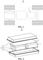
- Fig. 6 is a schematic structural diagram of a protective plate according to an embodiment of the present application.
- the protective plate 8 includes a first protective sheet 82, a second protective sheet 83 and a third protective sheet 84.
- the first protective sheet 82, the second protective sheet 83 and the third protective sheet 84 are sequentially away from the pressure relief mechanism 65.
- the preparation process of preparing the protective plate 8 from the first protective sheet 82, the second protective sheet 83 and the third protective sheet 84 is not limited in the present application. That is, the protective plate may be integrally formed, or different protective sheets may be prepared separately and then combined by means of hot pressing, etc. The following is described only by way of example.
- the first protective sheet 82, the second protective sheet 83 and the third protective sheet 84 may be prepared separately first.
- the fiber material layer 811 of the individual first protective sheet 82 is immersed into the resin material slurry, such that the resin material slurry is fully infiltrated into the fiber material layer 811 of the individual first protective sheet 82, and then baked at a temperature of 60°C-120°C for 3-30 minutes to prepare an individual fiber-reinforced resin layer 81 of the first protective sheet 82.
- the multiple individual fiber-reinforced resin layers 81 of the three different protective sheets described above are laminated in sequence, and hot-pressed under a pressure of 0.1-10 Mpa and a temperature of 100°C-200°C to form a protective plate 8.
- the number of fiber-reinforced resin layers 81 in the first protective sheet 82, the second protective sheet 83 and the third protective sheet 84 may be changed according to actual requirements.
- the resin materials of the first protective sheet 82, the second protective sheet 83 and the third protective sheet 84 may be changed according to requirements.
- the protective plate 8 includes three protective sheets, namely the first protective sheet 82, the second protective sheet 83 and the third protective sheet 84.
- the protective plate 8 made of the three protective sheets is disposed opposite the pressure relief mechanism 65, so that the protection effect of the protective plate 8 on the safety of the battery 2 can be further improved.
- the fiber material in the first protective sheet 82 is a carbon fiber or a quartz fiber.
- the carbon fiber refers to a high-strength and high-modulus fiber with a carbon content of 90% or more. Its high-temperature resistance capability ranks first among all fiber materials, and it is an excellent material for manufacturing high-tech equipment such as aerospace and aviation.
- the quartz fiber is a fiber material made from high-purity quartz or natural crystal, and is an excellent high-temperature resistant material.
- the first protective sheet 82 made of the carbon fiber or the quartz fiber can completely block the high temperature and the gas-solid impact released by the pressure relief mechanism 65.
- the first protective plate 82 made of the carbon fiber or the quartz fiber is used in the battery 2 to withstand high-temperature impact of about 1800°C.
- the first protective sheet 82, the second protective sheet 83 and the third protective sheet 84 are sequentially away from the pressure relief mechanism 65, that is, the first protective sheet 82 is closest to the pressure relief mechanism 65.
- the first protective sheet 82 made of the carbon fiber or the quartz fiber has the best high-temperature resistance effect and can reduce the influence on the performance of the battery.
- the fiber material in the second protective sheet 83 is a ceramic material or a high silica fiber.
- the ceramic fiber is a fiber material with ceramic components such as alumina added to the material.
- the ceramic fiber has an excellent high-temperature resistance capability.
- the second protective sheet 83 made of the ceramic fiber can withstand high-temperature impact of 1000°C, and can continue to protect the battery cell 6.
- the first protective sheet 82, the second protective sheet 83 and the third protective sheet 84 are sequentially away from the pressure relief mechanism 65, that is, the second protective sheet 83 is not closer to the pressure relief mechanism 65 than the first protective sheet 82.
- the second protective sheet 83 made of the ceramic fiber or the high silica fiber can save material costs.
- the second protective sheet 83 after the most high-temperature resistant first protective sheet 82 blocks the high temperature, the second protective sheet 83 also has a good high temperature resistance capability and continues to protect the battery 2 from the high temperature and the gas flow impact.
- the fiber material in the third protective sheet 84 is a glass fiber or a pre-ammonium fiber.
- the glass fiber and the pre-ammonia fiber are cheap and are the most commonly used reinforcement materials, electrical insulation materials and thermal insulation materials among composite materials.
- the temperature that the glass fiber and the pre-ammonia fiber can withstand is 180°C-430°C.
- the third protective sheet 84 made of the glass fiber or the pre-ammonia fiber can be used as the last layer of protection of the box 20 of the battery.
- the first protective sheet 82, the second protective sheet 83 and the third protective sheet 84 are sequentially away from the pressure relief mechanism 65, that is, the third protective sheet 84 is farthest from the pressure relief mechanism 65.
- the third protective sheet 84 withstands the lowest temperature released by the pressure relief mechanism 65. Therefore, using the glass fiber or the pre-ammonia fiber to make the third protective sheet 84 can further reduce the possibility of heat diffusion, protect the safety of the battery, and save costs to the greatest extent.
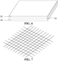
- Fig. 7 is a structural diagram of an arrangement of a fiber material according to an embodiment of the present application.
- each fiber-reinforced resin layer 81 of the plurality of fiber-reinforced resin layers 81 of the first protective sheet 82 includes fibers arranged in two directions.
- the first protective sheet 82 is closest to the pressure relief mechanism 65, and thus the first protective sheet 82 has the highest performance requirements.
- the first protective sheet 82 is closest to the pressure relief mechanism 65, and the first protective sheet 82 first comes into contact with the high temperature and the gas flow when they are released by the pressure relief mechanism 65. Therefore, the first protective sheet 82 has the highest requirements for high-temperature resistance and impact resistance capabilities.
- the first protective sheet 82 includes a plurality of fiber-reinforced resin layers 81, and each fiber-reinforced resin layer 81 of the plurality of fiber-reinforced resin layers 81 includes fibers arranged in two directions. The fiber material in such an arrangement has a higher strength, so that the protection effect of the first protective sheet 82 on the battery can be improved.
- each fiber-reinforced resin layer 81 of the plurality of fiber-reinforced resin layers 81 of each of the second protective sheet 83 and the third protective sheet 84 includes fibers arranged in the same direction, and different fiber-reinforced resin layers 81 are perpendicular to each other.
- the fiber material in each fiber-reinforced resin layer 81 of the first protective sheet 82 includes fibers arranged in two directions.
- the second protective sheet 83 and the third protective sheet 84 which do not have such high strength requirements, only need to maintain a certain strength.
- the arrangement of the fiber material in each fiber-reinforced resin layer 81 of the second protective sheet 83 and the third protective sheet 84 maintains a single orientation, which can maintain a certain strength and also reduce costs.
- the fiber material of each fiber-reinforced resin layer 81 of the plurality of fiber-reinforced resin layers 81 of each of the first protective sheet 82, the second protective sheet 83 and the third protective sheet 84 includes fibers arranged in two directions.
- each fiber-reinforced resin layer 81 includes two arrangement directions, the first protective sheet 82, the second protective sheet 83 and the third protective sheet 84 using this arrangement have a higher strength.
- the fiber materials in the plurality of fiber-reinforced resin layers 81 in different protective sheets include fibers arranged in two different directions, so that the protection effect of the protective plate 8 on the battery cell 6 can be further improved.
- the two arrangement directions are perpendicular to each other.
- the fiber material in the fiber-reinforced resin layer 81 includes fibers that are perpendicular to each other, the fiber material using this arrangement has the highest strength, and the protective plate 8 made of the fiber material in this arrangement has the best protection effect on the battery 6.
- a thickness ratio of the first protective sheet 82 to the protective plate 8 ranges from 1: 10 to 2:10.
- the first protective sheet 82 when the thickness of the first protective sheet 82 is 10% of the total thickness of the protective plate 8, the first protective sheet 82 can withstand the high temperature and the gas flow impact released by the pressure relief mechanism 65. When the thickness of the first protective sheet 82 is continued to be increased to 20% of the thickness of the protective plate 8, the protection effect of the first protective sheet 82 on the battery 2 can be improved. If the thickness of the first protective sheet 82 continues to increase, it will only increase the cost too much but have little effect on improving the protection effect.
- a thickness ratio of the second protective sheet 83 to the protective plate 8 ranges from 3:10 to 6:10.
- the second protective sheet 83 when the thickness of the second protective sheet 83 is between 30% and 60% of the total thickness of the protective plate 8, the second protective sheet 83 can continue to protect the battery 2 and save the overall production cost of the protective plate 8.
- a thickness ratio of the third protective sheet 84 to the protective plate 8 ranges from 2: 10 to 5:10.
- the third protective sheet 84 can continue to protect the battery 2 and save the overall production cost of the protective plate 8.
- a thickness ratio of the first protective sheet 82, the second protective sheet 83 and the third protective sheet 84 is 2:4:4.
- the high-temperature resistance capabilities of the first protective sheet 82, the second protective sheet 83 and the third protective sheet 84 decrease in sequence, and the material costs of the three also decrease in sequence.
- the protective plate 8 designed with the gradient fiber structure is disposed directly opposite the pressure relief mechanism 65, so that not only can the box 20 of the battery cell 6 be prevented from the high temperature and gas flow released by the pressure relief mechanism 65, and the safety of the battery cell 6 be protected, but the production cost of the protective plate 8 can also be reduced. Setting the thicknesses of the first protective sheet 82, the second protective sheet 83 and the third protective sheet 84 that are sequentially away from the pressure relief mechanism 65 to 2:4:4 can minimize material costs while reducing the influence on the performance of the battery 2.
- the resin material is a silicon-based aerogel modified resin or a high-temperature resistant flame retardant resin.
- the resin material in the embodiment of the present application may be a silicon-based aerogel modified resin or a high-temperature resistant flame retardant resin.
- the material made of a composite of fiber and resin has a high-temperature resistance and impact resistance performance.
- the use of the silicon-based aerogel modified resin or the high-temperature resistant flame retardant resin can further improve the high-temperature resistance and impact resistance performance of the protective plate 8.
- the fiber material has a thickness of 6-100 um.
- the thickness of the fiber material may be 10 um, 20 um, 50 um, etc., and can be appropriately adjusted according to requirements during the production process.
- the use of the fiber material with a thickness of 6-100 um can not only make the protective plate 8 have the high-temperature resistance and impact resistance performance, but can also reduce the production cost.
- the protective plate 8 has a thickness of 0.2-5 mm.
- the thickness of the protective plate 8 may be 1 mm, 2 mm or 3 mm, and can also be appropriately adjusted according to requirements during the production process.
- the use of the protective plate 8 with a thickness of 0.2-5 mm can not only make the protective plate 8 have the high-temperature resistance and impact resistance performance, but can also reduce the production cost.
- the battery cell 6 is accommodated in the box 20.
- the pressure relief mechanism is disposed on a first wall of the battery cell 6.
- the first wall is a wall of the battery cell 6 that is disposed close to a top cover 201 of the box 20 and opposite the top cover 201.
- the pressure relief mechanism 65 is close to and faces the top cover 201.
- the protective plate 8 is disposed between the pressure relief mechanism 65 and the top cover 201.
- the protective plate 8 made of the polymer matrix composite fibers can block the high temperature and the high-speed gas-solid mixture released by the pressure relief mechanism 65, reducing the possibility of the top cover 201 of the battery 2 suffering from the gas flow impact and the high-temperature melting, thereby protecting the safety of the battery 2.
- the protective plate 8 is integrated with the top cover 201.
- the protective plate 8 being integrated with the top cover 201, it is meant that the protective plate 8 and the top cover 201 may be used together as the top cover 201 of the battery 2, or the protective plate 8 may be used alone as the top cover 201 of the battery 2.
- the top cover 201 of the battery 2 has a two-layer structure, and the protective plate 8 protects the top cover 201 and thus better protects the battery 2.
- the protective plate 8 can not only protect the top cover 201 of the battery 2 from the high temperature and the gas flow impact, but can also make the structure of the battery 2 simpler and reduce the production cost of the battery 2.
- the top cover 201 may have an irregular shape.
- the top cover 201 may also be square, round, etc., which is not limited in the present application. That is, during the production process, the top cover 201 and the protective plate 8 can be manufactured in any shape according to specific product requirements.
- the protective plate 8 is disposed between the top cover 201 and the first wall.
- the protective plate 8 is disposed between the top cover 201 and the first wall, that is, the pressure relief mechanism 65 faces the top cover 201, and the protective plate 8 is disposed between the top cover 201 and the pressure relief mechanism 65.
- the protective plate 8 is disposed between the top cover 201 and the pressure relief structure 65, and the pressure relief mechanism 65 faces the top cover 201. In this way, the protective plate 8 can directly protect the top cover 201, so that the top cover 201 directly facing the pressure relief mechanism 65 is protected from the high temperature and the gas flow impact, thereby reducing the influence on the performance of the battery 2.
- the size of the protective plate 8 is the same as that of the top cover 201.
- the protective plate 8 is disposed between the top cover 201 and the pressure relief structure 65 and the size of the protective plate 8 is the same as that of the top cover 201, so that the protective plate 8 can protect the top cover 201 more comprehensively.
- the protective plate 8 when the protective plate 8 is disposed between the top cover 201 and the pressure relief structure 65 and the size of the protective plate 8 is the same as that of the top cover 201, the protective plate 8 can not only protect the top cover 201 more comprehensively so that the top cover 201 is protected from the high temperature and the high-speed gas-solid mixture released by the pressure relief mechanism 65, but can also improve the sealing effect on the interior of the battery 2.
- the same size of the protective plate 8 and the top cover 201 also facilitates assembly and reduces the difficulty of assembly.
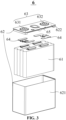
- Fig. 8 is an exploded schematic structural diagram of a battery according to still another embodiment of the present application. As shown in Fig. 8 , optionally, the size of the protective plate 8 is less than that of the top cover 201.
- the protective plate 8 is disposed between the top cover 201 and the first wall provided with the pressure relief mechanism 65.
- the protective plate 8 can not only protect the top cover 201 to improve the safety performance of the battery 2, but can also reduce the production cost.
- Fig. 9 is an exploded schematic structural diagram of a battery according to still another embodiment of the present application.
- the protective plate 8 is strip-shaped, and the projection of the protective plate 8 on the first wall covers the pressure relief mechanism 65.
- the protective plate 8 may be in the shape of a strip as shown in Fig. 9 , or may be in the shape of a circle, or any other shape, as long as the projection of the protective plate 8 on the first wall covers the pressure relief mechanism 65, and the function of protecting the box 20 of the battery 2 can be achieved.
- the shape of the protective plate 8 is not limited in the present application.
- the protective plate 8 is disposed between the top cover 201 and the first wall.
- the protective plate 8 is strip-shaped and the projection thereof on the first wall covers the pressure relief mechanism 65, the protective plate 8 can maintain a good protection effect on the top cover 201, and can also reduce the cost to the greatest extent and avoid the waste of materials in non-protected areas.
- the length of the protective plate 8 is 1 to 3 times the length of the pressure relief mechanism 65 in a first direction X.
- the first direction X is an extension direction of the protective plate 8.
- the length of the protective plate 8 is 1 to 3 times the length of the pressure relief mechanism 65 in the first direction X, so that the protective plate 8 can completely cover the pressure relief mechanism 65, and the defending effect of the protective plate 8 on the pressure relief mechanism 65 can be improved.
- each protective plate 8 there are a plurality of block-shaped protective plates 8, and a projection of each protective plate 8 on the first wall covers a respective pressure relief mechanism 65.
- the protective plate 8 is disposed between the top cover 201 and the first wall.
- Each protective plate 8 is block-shaped and the projection thereof on the first wall covers the respective pressure relief mechanism 65.
- Each block-shaped plate is individually arranged above the corresponding pressure relief mechanism 65 to form a one-to-one protection to accurately defend the respective pressure relief mechanism 65.
- each protective plate is 1-2 times the area of the respective pressure relief mechanism 65.
- the block-shaped protective plate 8 implements one-to-one protection for a respective pressure relief mechanism 65 for precise protection.
- the area of each block-shaped protective plate 8 is 1-2 times the area of the respective pressure relief mechanism 65, further improving the protection effect of the protective plate 8 on the battery 2.
- the protective plate 8 is connected to the top cover 201 by means of bolts or an adhesive.
- connection method is not limited in the present application. However, in the actual production process, choosing a convenient and operable connection method is conducive to widespread promotion in actual applications.
- the bolt or adhesive is used to realize the connection between the protective plate 8 and the top cover 201.
- This connection method is simple to implement, has strong operability, and is conducive to widespread use in production.
- the battery cell 6 is accommodated in the box 20.
- the pressure relief mechanism 65 is disposed on a first wall of the battery cell.
- the first wall is a wall of the battery cell 6 that is disposed close to a bottom wall of the box 20 and opposite the bottom wall.
- the pressure relief mechanism 65 is close to and faces the bottom wall.
- the protective plate 8 is disposed between the pressure relief mechanism 65 and the bottom wall.
- the protective plate 8 made of the polymer matrix composite fibers can block the high temperature and the high-speed gas-solid mixture released by the pressure relief mechanism 65, protecting the bottom wall of the battery 2 from the gas flow impact and the high-temperature melting, thereby protecting the safety of the battery 2.
- the protective plate 8 is integrated with the bottom wall.
- the protective plate 8 being integrated with the bottom wall, it is meant that the protective plate 8 and the bottom wall may be used together as the bottom wall of the battery 2, or the protective plate 8 may be used alone as the bottom wall of the battery 2.
- the bottom wall of the battery 2 has a two-layer structure, and the protective plate 8 protects the bottom wall and thus better protects the battery 2.
- the protective plate 8 can not only protect the bottom wall of the battery 2 from the high temperature and the gas flow impact, but can also make the structure of the battery 2 simpler and reduce the production cost of the battery 2.
- the protective plate 8 When the pressure relief mechanism 65 inside the battery 2 only faces the top cover 201, the protective plate 8 is integrated with the top cover 201 to protect the safety of the battery 2; and when the pressure relief mechanism 65 only faces the bottom wall, the protective plate 8 is integrated with the bottom wall to protect the safety of battery 2.
- protective plates 8 When there are pressure relief mechanisms 65 inside the battery 2 that face both the top cover 201 and the bottom wall, protective plates 8 may be provided at both the top cover 201 and the bottom wall.
- the arrangement of the protective plate 8 in the battery 2 is not specifically limited in the present application, as long as the protective plate 8 is present at the wall directly facing the pressure relief mechanism 65 of the battery cell 6 in the battery 2. That is, the protective plate 8 may be the top cover 201, the bottom wall and a side wall. Furthermore, the protective plate 8 may be a crossbeam in the battery 2. The specific position of the protective plate 8 may be modified according to the arrangement position of the battery cell 6 in the battery 2, or the protective plate may be disposed at any position in the battery 2 according to actual
- the protective plate 8 is disposed between the bottom wall and the first wall.
- the protective plate 8 is disposed between the bottom wall and the first wall, that is, the pressure relief mechanism 65 faces the bottom wall, and the protective plate 8 is disposed between the bottom wall and the pressure relief mechanism 65.
- the protective plate 8 is disposed between the bottom wall and the pressure relief structure 65, and the pressure relief mechanism 65 faces the top cover 201. In this way, the protective plate 8 can directly protect the bottom wall, so that the bottom wall directly facing the pressure relief mechanism 65 is protected from the high temperature and the gas flow impact, thereby reducing the influence on the performance of the battery 2.
- Fig. 10 is a schematic structural diagram of a protective plate according to another embodiment of the present application. As shown in Fig. 10 , in an embodiment of the present application, a thermal insulation component 67 is disposed between the protective plate 8 and the box 20.
- adding a protective plate 8 between the first wall provided with the pressure relief mechanism 65 and the box 20 can protect the box 20 of the battery 2 from the high temperature and the high-speed gas flow impact. Further providing a thermal insulation component 67 between the protective plate 8 and the box 20 can further reduce the temperature of the box 20 and protect the safety of the battery 2.
- An embodiment of the present application further provides an electrical device, including a battery 2 according to the above embodiments.
- the battery 2 is configured to supply electric energy.
Landscapes
- Chemical & Material Sciences (AREA)
- Chemical Kinetics & Catalysis (AREA)
- Electrochemistry (AREA)
- General Chemical & Material Sciences (AREA)
- Engineering & Computer Science (AREA)
- Manufacturing & Machinery (AREA)
- Battery Mounting, Suspending (AREA)
- Gas Exhaust Devices For Batteries (AREA)
Applications Claiming Priority (2)
| Application Number | Priority Date | Filing Date | Title |
|---|---|---|---|
| CN202210748421.7A CN117352916A (zh) | 2022-06-29 | 2022-06-29 | 电池和用电设备 |
| PCT/CN2023/090981 WO2024001482A1 (zh) | 2022-06-29 | 2023-04-26 | 电池和用电设备 |
Publications (2)
| Publication Number | Publication Date |
|---|---|
| EP4510312A1 true EP4510312A1 (de) | 2025-02-19 |
| EP4510312A4 EP4510312A4 (de) | 2025-05-21 |
Family
ID=89356221
Family Applications (1)
| Application Number | Title | Priority Date | Filing Date |
|---|---|---|---|
| EP23829669.3A Pending EP4510312A4 (de) | 2022-06-29 | 2023-04-26 | Batterie und elektrische vorrichtung |
Country Status (4)
| Country | Link |
|---|---|
| US (1) | US20250070375A1 (de) |
| EP (1) | EP4510312A4 (de) |
| CN (1) | CN117352916A (de) |
| WO (1) | WO2024001482A1 (de) |
Families Citing this family (3)
| Publication number | Priority date | Publication date | Assignee | Title |
|---|---|---|---|---|
| DE102024104888A1 (de) * | 2024-02-21 | 2025-08-21 | Sgl Carbon Se | Energiespeichervorrichtung |
| CN222654235U (zh) * | 2024-04-30 | 2025-03-21 | 惠州亿纬锂能股份有限公司 | 一种电池包 |
| CN119348715A (zh) * | 2024-10-29 | 2025-01-24 | 岚图汽车科技有限公司 | 汽车底板及汽车 |
Family Cites Families (6)
| Publication number | Priority date | Publication date | Assignee | Title |
|---|---|---|---|---|
| US20160211495A1 (en) * | 2015-01-20 | 2016-07-21 | Williams Grand Prix Engineering Limited | Fire guards and materials therefor |
| CN205944199U (zh) * | 2016-08-12 | 2017-02-08 | 宁德时代新能源科技股份有限公司 | 一种电池 |
| KR102665241B1 (ko) * | 2018-11-13 | 2024-05-09 | 리비안 아이피 홀딩스, 엘엘씨 | 복합체 구조를 갖는 전기 자동차 배터리 팩 커버 |
| JP7577686B2 (ja) * | 2019-05-02 | 2024-11-05 | エリコン フリクション システムズ(ジャーマニー) ゲーエムベーハー | 熱シールド |
| CN110148692A (zh) * | 2019-05-10 | 2019-08-20 | 北京新能源汽车股份有限公司 | 电池模组及具有其的车辆 |
| CN111730876A (zh) * | 2020-07-10 | 2020-10-02 | 苏州银禧新能源复合材料有限公司 | 复合电池箱上盖的成型工艺 |
-
2022
- 2022-06-29 CN CN202210748421.7A patent/CN117352916A/zh active Pending
-
2023
- 2023-04-26 EP EP23829669.3A patent/EP4510312A4/de active Pending
- 2023-04-26 WO PCT/CN2023/090981 patent/WO2024001482A1/zh not_active Ceased
-
2024
- 2024-11-14 US US18/946,960 patent/US20250070375A1/en active Pending
Also Published As
| Publication number | Publication date |
|---|---|
| US20250070375A1 (en) | 2025-02-27 |
| WO2024001482A1 (zh) | 2024-01-04 |
| CN117352916A (zh) | 2024-01-05 |
| EP4510312A4 (de) | 2025-05-21 |
Similar Documents
| Publication | Publication Date | Title |
|---|---|---|
| EP4510312A1 (de) | Batterie und elektrische vorrichtung | |
| EP4395016A1 (de) | Batterie und elektrische vorrichtung | |
| EP4404353A1 (de) | Batterie und elektrische vorrichtung | |
| CN219643037U (zh) | 电池和用电装置 | |
| CN220209101U (zh) | 电池单体、电池及用电装置 | |
| CN216720146U (zh) | 电池和用电设备 | |
| CN219203231U (zh) | 电池以及用电装置 | |
| CN219180683U (zh) | 电池以及用电装置 | |
| US20230089208A1 (en) | Battery, power consumption apparatus, and method and apparatus for producing battery | |
| US20240313299A1 (en) | Battery module, battery, and power consuming device | |
| US20240274975A1 (en) | Battery and electrical device | |
| CN115642353A (zh) | 电池模组、电池包及用电设备 | |
| CN118044059A (zh) | 用于电池单体的端盖组件、电池单体、电池和用电设备 | |
| CN222637338U (zh) | 一种电芯、二次电池和用电装置 | |
| KR20240129189A (ko) | 전지 및 전기기기 | |
| CN219226401U (zh) | 电池和用电装置 | |
| CN219203305U (zh) | 电池和用电装置 | |
| CN222851528U (zh) | 电池单体、电池装置及用电设备 | |
| US20240243424A1 (en) | Battery, power consumption apparatus, method and apparatus for preparing battery | |
| CN220710396U (zh) | 电池模组、电池和用电装置 | |
| CN222838934U (zh) | 电池及用电装置 | |
| CN220774634U (zh) | 电池包和用电装置 | |
| WO2023070399A1 (zh) | 电池、用电装置及电池的制造方法 |
Legal Events
| Date | Code | Title | Description |
|---|---|---|---|
| STAA | Information on the status of an ep patent application or granted ep patent |
Free format text: STATUS: THE INTERNATIONAL PUBLICATION HAS BEEN MADE |
|
| PUAI | Public reference made under article 153(3) epc to a published international application that has entered the european phase |
Free format text: ORIGINAL CODE: 0009012 |
|
| STAA | Information on the status of an ep patent application or granted ep patent |
Free format text: STATUS: REQUEST FOR EXAMINATION WAS MADE |
|
| 17P | Request for examination filed |
Effective date: 20241113 |
|
| AK | Designated contracting states |
Kind code of ref document: A1 Designated state(s): AL AT BE BG CH CY CZ DE DK EE ES FI FR GB GR HR HU IE IS IT LI LT LU LV MC ME MK MT NL NO PL PT RO RS SE SI SK SM TR |
|
| A4 | Supplementary search report drawn up and despatched |
Effective date: 20250417 |
|
| RIC1 | Information provided on ipc code assigned before grant |
Ipc: H01M 50/383 20210101ALI20250411BHEP Ipc: H01M 50/209 20210101ALI20250411BHEP Ipc: H01M 50/204 20210101ALI20250411BHEP Ipc: H01M 10/658 20140101AFI20250411BHEP |
|
| DAV | Request for validation of the european patent (deleted) | ||
| DAX | Request for extension of the european patent (deleted) |