EP4509762A2 - Method for controlling the cleaning of a cooking appliance - Google Patents
Method for controlling the cleaning of a cooking appliance Download PDFInfo
- Publication number
- EP4509762A2 EP4509762A2 EP24187083.1A EP24187083A EP4509762A2 EP 4509762 A2 EP4509762 A2 EP 4509762A2 EP 24187083 A EP24187083 A EP 24187083A EP 4509762 A2 EP4509762 A2 EP 4509762A2
- Authority
- EP
- European Patent Office
- Prior art keywords
- heater
- temperature
- cavity
- operate
- bake
- Prior art date
- Legal status (The legal status is an assumption and is not a legal conclusion. Google has not performed a legal analysis and makes no representation as to the accuracy of the status listed.)
- Pending
Links
- 238000010411 cooking Methods 0.000 title claims abstract description 91
- 238000000034 method Methods 0.000 title claims abstract description 77
- 238000004140 cleaning Methods 0.000 title claims abstract description 40
- 239000005416 organic matter Substances 0.000 description 83
- 238000007254 oxidation reaction Methods 0.000 description 41
- 230000003647 oxidation Effects 0.000 description 32
- 238000005979 thermal decomposition reaction Methods 0.000 description 29
- 238000010438 heat treatment Methods 0.000 description 21
- 230000008569 process Effects 0.000 description 20
- 230000000694 effects Effects 0.000 description 16
- 230000008859 change Effects 0.000 description 10
- 230000000052 comparative effect Effects 0.000 description 10
- 238000002474 experimental method Methods 0.000 description 10
- 239000000463 material Substances 0.000 description 9
- 230000005855 radiation Effects 0.000 description 5
- QVGXLLKOCUKJST-UHFFFAOYSA-N atomic oxygen Chemical compound [O] QVGXLLKOCUKJST-UHFFFAOYSA-N 0.000 description 4
- 229910052760 oxygen Inorganic materials 0.000 description 4
- 239000001301 oxygen Substances 0.000 description 4
- 239000004215 Carbon black (E152) Substances 0.000 description 2
- UGFAIRIUMAVXCW-UHFFFAOYSA-N Carbon monoxide Chemical compound [O+]#[C-] UGFAIRIUMAVXCW-UHFFFAOYSA-N 0.000 description 2
- 230000004913 activation Effects 0.000 description 2
- 229910002091 carbon monoxide Inorganic materials 0.000 description 2
- 238000010586 diagram Methods 0.000 description 2
- 230000020169 heat generation Effects 0.000 description 2
- 229930195733 hydrocarbon Natural products 0.000 description 2
- 150000002430 hydrocarbons Chemical class 0.000 description 2
- 229910052739 hydrogen Inorganic materials 0.000 description 2
- 239000001257 hydrogen Substances 0.000 description 2
- 238000013021 overheating Methods 0.000 description 2
- UFHFLCQGNIYNRP-UHFFFAOYSA-N Hydrogen Chemical compound [H][H] UFHFLCQGNIYNRP-UHFFFAOYSA-N 0.000 description 1
- 239000002956 ash Substances 0.000 description 1
- 238000006243 chemical reaction Methods 0.000 description 1
- 230000003247 decreasing effect Effects 0.000 description 1
- 230000001419 dependent effect Effects 0.000 description 1
- 230000002542 deteriorative effect Effects 0.000 description 1
- 150000002431 hydrogen Chemical class 0.000 description 1
- 238000012986 modification Methods 0.000 description 1
- 230000004048 modification Effects 0.000 description 1
- 238000012546 transfer Methods 0.000 description 1
- 239000013585 weight reducing agent Substances 0.000 description 1
Images




Classifications
-
- F—MECHANICAL ENGINEERING; LIGHTING; HEATING; WEAPONS; BLASTING
- F24—HEATING; RANGES; VENTILATING
- F24C—DOMESTIC STOVES OR RANGES ; DETAILS OF DOMESTIC STOVES OR RANGES, OF GENERAL APPLICATION
- F24C14/00—Stoves or ranges having self-cleaning provisions, e.g. continuous catalytic cleaning or electrostatic cleaning
- F24C14/02—Stoves or ranges having self-cleaning provisions, e.g. continuous catalytic cleaning or electrostatic cleaning pyrolytic type
-
- F—MECHANICAL ENGINEERING; LIGHTING; HEATING; WEAPONS; BLASTING
- F24—HEATING; RANGES; VENTILATING
- F24C—DOMESTIC STOVES OR RANGES ; DETAILS OF DOMESTIC STOVES OR RANGES, OF GENERAL APPLICATION
- F24C15/00—Details
- F24C15/20—Removing cooking fumes
- F24C15/2007—Removing cooking fumes from oven cavities
- F24C15/2014—Removing cooking fumes from oven cavities with means for oxidation of cooking fumes
-
- F—MECHANICAL ENGINEERING; LIGHTING; HEATING; WEAPONS; BLASTING
- F24—HEATING; RANGES; VENTILATING
- F24C—DOMESTIC STOVES OR RANGES ; DETAILS OF DOMESTIC STOVES OR RANGES, OF GENERAL APPLICATION
- F24C15/00—Details
- F24C15/32—Arrangements of ducts for hot gases, e.g. in or around baking ovens
- F24C15/322—Arrangements of ducts for hot gases, e.g. in or around baking ovens with forced circulation
-
- F—MECHANICAL ENGINEERING; LIGHTING; HEATING; WEAPONS; BLASTING
- F24—HEATING; RANGES; VENTILATING
- F24C—DOMESTIC STOVES OR RANGES ; DETAILS OF DOMESTIC STOVES OR RANGES, OF GENERAL APPLICATION
- F24C7/00—Stoves or ranges heated by electric energy
- F24C7/06—Arrangement or mounting of electric heating elements
- F24C7/067—Arrangement or mounting of electric heating elements on ranges
-
- F—MECHANICAL ENGINEERING; LIGHTING; HEATING; WEAPONS; BLASTING
- F24—HEATING; RANGES; VENTILATING
- F24C—DOMESTIC STOVES OR RANGES ; DETAILS OF DOMESTIC STOVES OR RANGES, OF GENERAL APPLICATION
- F24C7/00—Stoves or ranges heated by electric energy
- F24C7/08—Arrangement or mounting of control or safety devices
- F24C7/082—Arrangement or mounting of control or safety devices on ranges, e.g. control panels, illumination
- F24C7/085—Arrangement or mounting of control or safety devices on ranges, e.g. control panels, illumination on baking ovens
-
- F—MECHANICAL ENGINEERING; LIGHTING; HEATING; WEAPONS; BLASTING
- F24—HEATING; RANGES; VENTILATING
- F24C—DOMESTIC STOVES OR RANGES ; DETAILS OF DOMESTIC STOVES OR RANGES, OF GENERAL APPLICATION
- F24C7/00—Stoves or ranges heated by electric energy
- F24C7/08—Arrangement or mounting of control or safety devices
- F24C7/087—Arrangement or mounting of control or safety devices of electric circuits regulating heat
Definitions
- the present disclosure relates to a method for controlling cleaning of a cooking appliance, and more particularly, to a method for controlling cleaning of a cooking appliance that is used in a removal process of organic matter in a thermal decomposition scheme.
- a cooking appliance one of home appliances, has a cavity that accommodates food to be cooked therein.
- the cavity is defined as a space by panels.
- the cooking appliance is equipped with the cavity and a heating device to heat the food.
- a heating device to heat the food.
- the cavity and the food are heated at a high temperature, so that organic matter contained in the food may splash or spill into the cavity.
- the organic matter from the food may be attached to a surface of the panel constituting the cavity.
- the cooking appliance may have a self-clean function to remove such organic matter on its own.
- the self-clean is a separate function that is distinct from a cooking function of the cooking appliance.
- the cooking appliance may operate a self-clean mode when not performing the cooking to remove the organic matter attached to the panel.
- the self-clean involves operating the heating device equipped in the cooking appliance to heat the cavity at the high temperature to thermally decompose and remove the organic matter attached to the surface of the panel.
- the organic matter may react with oxygen in air at the high temperature and be oxidized, and thus be separated and removed from the panel.
- the lower the oxidation temperature at which the organic matter reacts with oxygen in air the easier the thermal decomposition of the organic matter may occur. Additionally, as a thermal decomposition amount of the organic matter increases during the thermal decomposition process, the organic matter may be effectively removed.
- the present disclosure is to provide a method for controlling cleaning of a cooking appliance that has a structure that may easily remove organic matter attached to a panel constituting a cavity.
- the present disclosure is to provide a method for controlling cleaning of a cooking appliance that has a structure that may lower an oxidation temperature of organic matter and increase a thermal decomposition amount in a self-clean mode.
- the present disclosure is to provide a method for controlling cleaning of a cooking appliance that controls a temperature increase rate of a cavity to lower an oxidation temperature of organic matter and increase a thermal decomposition amount in a self-clean mode.
- An embodiment of a method for controlling cleaning of a cooking appliance includes a mode selecting step of selecting a self-clean mode of a cavity, a temperature increasing step of increasing an internal temperature of the cavity to a set second temperature, and a temperature maintaining step of maintaining the internal temperature of the cavity at the second temperature.
- the temperature increasing step includes controlling a temperature increase rate inside the cavity in the temperature increasing step by operating a broil heater and a bake heater alternately.
- An oxidation temperature of organic matter may be lowered and a thermal decomposition amount of the organic matter may be increased by controlling the temperature increase rate inside the cavity.
- the temperature increasing step may include a first step of increasing the internal temperature of the cavity to a first temperature, and a second step of increasing the internal temperature of the cavity to reach the second temperature from the first temperature.
- a temperature increase rate inside the cavity in the first step may be set higher than a temperature increase rate inside the cavity in the second step. Accordingly, a removal effect of the organic matter may be improved by increasing a time during which an oxidation reaction of the organic matter occurs.
- the outer heater may operate continuously, the inner heater and the bake heater may operate in a continuous manner and operate alternately with each other, and an operation time of the bake heater may be set larger than an operation time of the inner heater. Accordingly, the temperature increase rate of the cavity may be maintained approximately uniformly in the temperature increasing step.
- the outer heater may not operate, and the inner heater and the bake heater may operate in a continuous manner and operate alternately with each other to increase the temperature of the cavity. Accordingly, power consumption resulted from the heater operation in the temperature increasing step may be reduced.
- a cooking appliance includes a cavity where food to be cooked is accommodated, a broil heater that applies radiant heat to the cavity, and a bake heater that heats a panel constituting the cavity.
- a method for controlling cleaning of a cooking appliance includes a mode selecting step of selecting a self-clean mode of a cavity, a temperature increasing step of increasing an internal temperature of the cavity to a set second temperature, and a temperature maintaining step of maintaining the internal temperature of the cavity at the second temperature.
- the temperature increasing step includes controlling a temperature increase rate inside the cavity in the temperature increasing step by operating a broil heater and a bake heater alternately.
- the broil heater may include an inner heater disposed at an upper portion of the cavity, and an outer heater disposed at the upper portion of the cavity to surround the inner heater, wherein the outer heater has an output lower than an output of the inner heater.
- the temperature increasing step may include alternately operating the inner heater and the bake heater to control the temperature increase rate inside the cavity.
- the temperature increasing step may include a first step of increasing the internal temperature of the cavity to a first temperature set lower than the second temperature, and a second step of increasing the internal temperature of the cavity to reach the second temperature from the first temperature.
- a temperature increase rate inside the cavity in the first step may be set higher than a temperature increase rate inside the cavity in the second step.
- the outer heater may operate continuously, and the inner heater and the bake heater may operate in a continuous manner and operate alternately with each other.
- the outer heater may operate continuously, and the inner heater and the bake heater may operate alternately with each other, but there may be a time period where both the inner heater and the bake heater do not operate.
- the outer heater may operate continuously, and the inner heater and the bake heater may operate in a continuous manner and operate alternately with each other.
- the outer heater may not operate, and the inner heater and the bake heater may operate in a continuous manner and operate alternately with each other.
- the outer heater may not operate, and the inner heater and the bake heater may operate alternately with each other, but there may be a time period where both the inner heater and the bake heater do not operate.
- the outer heater may not operate, and the inner heater and the bake heater may operate in a continuous manner and operate alternately with each other.
- the outer heater may operate continuously, the inner heater and the bake heater may operate in a continuous manner and operate alternately with each other, and an operation time of the bake heater may be set larger than an operation time of the inner heater.
- the outer heater may operate continuously, the inner heater and the bake heater may operate in a continuous manner and operate alternately with each other, and an operation time of the bake heater may be set larger than an operation time of the inner heater.
- the outer heater may not operate, the inner heater and the bake heater may operate in a continuous manner and operate alternately with each other, and an operation time of the bake heater may be set larger than an operation time of the inner heater.
- the outer heater may not operate, the inner heater and the bake heater may operate in a continuous manner and operate alternately with each other, and an operation time of the bake heater may be set larger than an operation time of the inner heater.
- a cooking appliance includes a cavity where food to be cooked is accommodated, an inner heater disposed at an upper portion of the cavity, and an outer heater disposed at the upper portion of the cavity to surround the inner heater, wherein the outer heater has an output lower than an output of the inner heater.
- the cooking appliance includes a bake heater that heats a panel constituting the cavity.
- a method for controlling cleaning of a cooking appliance includes a temperature increasing step of increasing an internal temperature of a cavity to a set second temperature, and a temperature maintaining step of maintaining the internal temperature of the cavity at the second temperature.
- the temperature increasing step includes a first step of increasing the internal temperature of the cavity to a first temperature set lower than the second temperature, and a second step of increasing the internal temperature of the cavity to reach the second temperature from the first temperature.
- a temperature increase rate inside the cavity in the first step is set higher than a temperature increase rate inside the cavity in the second step.
- the outer heater may operate continuously, and the inner heater and the bake heater may operate in a continuous manner and operate alternately with each other.
- the outer heater may operate continuously, and the inner heater and the bake heater may operate alternately with each other, but there may be a time period where both the inner heater and the bake heater do not operate.
- the outer heater may operate continuously, and the inner heater and the bake heater may operate in a continuous manner and operate alternately with each other.
- a method for controlling cleaning of a cooking appliance includes a cavity where food to be cooked is accommodated, a heater that heats the interior of the cavity, and a controller that controls the heater.
- the method includes a temperature increasing step of increasing an internal temperature of the cavity to a set second temperature, and a temperature maintaining step of maintaining the internal temperature of the cavity at the second temperature.
- the temperature increasing step may include a first step of increasing the internal temperature of the cavity to a first temperature set lower than the second temperature, and a second step of increasing the internal temperature of the cavity to reach the second temperature from the first temperature.
- a temperature increase rate inside the cavity in the first step may be set higher than a temperature increase rate inside the cavity in the second step.
- the heater may include a plurality of heaters, and in the second step, there may be a time period where some of the plurality of heaters operating in the first step do not operate.
- the heater may include an inner heater disposed at an upper portion of the cavity, an outer heater disposed at the upper portion of the cavity to surround the inner heater, wherein the outer heater has an output lower than an output of the inner heater, and a bake heater that heats a panel constituting the cavity.
- the temperature increasing step may include controlling the temperature increase rate inside the cavity by operating the inner heater and the bake heater alternately.
- the outer heater may operate continuously, and the inner heater and the bake heater may operate in a continuous manner and operate alternately with each other.
- the outer heater may operate continuously, and the inner heater and the bake heater may operate alternately with each other, but there may be a time period where both the inner heater and the bake heater do not operate.
- the outer heater may not operate, and the inner heater and the bake heater may operate in a continuous manner and operate alternately with each other.
- the outer heater may not operate, and the inner heater and the bake heater may operate alternately with each other, but there may be a time period where both the inner heater and the bake heater do not operate.
- the outer heater may operate continuously, and the inner heater and the bake heater may operate in a continuous manner and operate alternately with each other.
- a method for controlling cleaning of a cooking appliance includes a temperature increasing step of increasing an internal temperature of a cavity to a set second temperature, and a temperature maintaining step of maintaining the internal temperature of the cavity at the second temperature.
- the inner heater and the bake heater operate in a continuous manner and operate alternately with each other, and an operation time of the bake heater is set larger than an operation time of the inner heater.
- the temperature of the cavity may be increased relatively quickly up to the first temperature that is close to the oxidation temperature of the organic matter, and the temperature increase rate may be reduced when the first temperature is reached.
- the removal effect of the organic matter may be increased by increasing the time from the time point at which the oxidation reaction of the organic matter occurs to the time point of reaching the second temperature, and thus increasing the time during which the oxidation reaction of the organic matter occurs.
- the oxidation temperature of the organic matter may be effectively lowered and the thermal decomposition amount may be effectively increased by maintaining the temperature increase rate of the cavity approximately uniformly in the temperature increasing step.
- the temperature increase rate of the cavity may decrease in the temperature increasing step. Therefore, while proceeding the self-clean mode, the time for which the temperature of the cavity is maintained at the second temperature, which is the maximum temperature, may be reduced.
- the total heating amount inside the cooking appliance may decrease while proceeding the self-clean mode.
- the overheating of the cooking appliance may be suppressed, thereby effectively preventing the fire from occurring in the electrical devices and other combustible components disposed in the cooking appliance.
- a and/or B means A, B, or A and B, unless otherwise specified, and "C to D” means C inclusive to D inclusive unless otherwise specified.
- up, down, front, rear refers to a location of a cooking appliance when the cooking appliance is installed for daily use.
- a vertical direction refers to a vertical direction of the cooking appliance when the cooking appliance is installed for daily use.
- a “left and right direction” refers to a direction perpendicular to the vertical direction, and a front and rear direction refers to a direction perpendicular to both the vertical direction and the left and right direction.
- a “lateral direction” may have the same meaning as the left and right direction, and these terms may be used interchangeably herein.
- FIG. 1 is a diagram schematically showing a cooking appliance according to an embodiment.
- the cooking appliance may include a cavity 100, which is a space in which food to be cooked is accommodated.
- the food to be cooked may be placed in the cavity 100 and may be heated at a high temperature.
- the cooking appliance may have a panel 400 to define the cavity 100.
- the panel 400 may be open at a front side facing a door and may include a side plate, a bottom plate 410, and a ceiling plate 420.
- the side plate may form a side wall of the cavity 100
- the bottom plate 410 may form a bottom of the cavity 100
- the ceiling plate 420 may form a ceiling of the cavity 100.
- the food placed in the cavity 100 may be heated in a high-temperature environment.
- the cooking appliance may be equipped with a heater to heat the cavity 100.
- the cavity 100 may be heated using the heater disposed in the cooking appliance, so that the organic matter may be removed via thermal decomposition.
- a reaction formula for the thermal decomposition is as follows. organic matter + O 2 + heat ⁇ CO + H 2 + CmHn + ash
- the organic matter when heat is applied to the organic matter, the organic matter may react with oxygen in air and be oxidized, so that carbon monoxide, hydrogen, hydrocarbon, and ash may be generated as products of the oxidation of the organic matter. Carbon monoxide and hydrogen go into air, and hydrocarbon and ash fall from a surface of the panel 400, so that the organic matter attached to the panel 400 may be removed.
- the cavity 100 may be heated at the high temperature, for example, at a temperature equal to or higher than approximately 400°C.
- the heating of the cavity 100 may be carried out by the heater disposed in the cooking appliance.
- Such organic matter removal process using the thermal decomposition scheme may be carried out separately from a cooking process of the cooking appliance.
- a method for controlling cleaning of a cooking appliance according to an embodiment relates to a method for controlling cleaning of a cooking appliance used in the removal process of the organic matter using the thermal decomposition scheme.
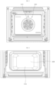
- FIG. 2 is a view of the ceiling plate 420 from inside the cavity 100 of the cooking appliance according to an embodiment.
- FIG. 3 is a rear view from inside the cavity 100 of the cooking appliance according to an embodiment.
- FIG. 4 is a view of the bottom plate 410 from inside the cavity 100 of the cooking appliance according to an embodiment.
- the cooking appliance may include a broil heater 200, a bake heater 300, and a convection heater 500.
- Such heaters may be operated via, for example, an electric resistance heating scheme.
- the broil heater 200 may apply radiant heat to the cavity 100.
- the broil heater 200 may be disposed at an upper portion of the cavity 100, that is, at a location adjacent to the ceiling plate 420 of the panel 400, and may be equipped as a heating tube and heated to heat air in the cavity 100 by applying the radiant heat to the cavity 100.
- the bake heater 300 may heat the panel 400 constituting the cavity 100.
- the bake heater 300 may be disposed under the bottom plate 410 of the panel 400 and disposed outside the cavity 100.
- the bake heater 300 may be equipped as a plate-shaped heating element or a heating tube and apply the radiant heat to the bottom plate 410.
- the heat from the bottom plate 410 heated by the bake heater 300 may be transferred to an entirety of the panel 400 via conduction.
- the panel 400 heated as such may apply the radiant heat to the cavity 100. Therefore, the bake heater 300 may heat air in the cavity 100 by transferring the heat sequentially via radiation, conduction, and radiation.
- the convection heater 500 may be disposed at a rear portion of the cavity 100 to extend through the panel 400, and may include a fan 510 and a convection heating unit 520.
- the convection heating unit 520 may be equipped as a heating tube and be heated.
- the fan 510 may be disposed in front of the convection heating unit 520 and operate to circulate air inside the cavity 100. Accordingly, the heat of the convection heating unit 520 may heat air in the cavity 100 via convection.
- the convection heater 500 disposed in the cooking appliance may operate to cook the food.
- the convection heating unit 520 of the convection heater 500 may not operate.
- a temperature increase rate inside the cavity 100 is excessively high, so that the cavity 100 may be heated using the broil heater 200 and the bake heater 300 without using the convection heating unit 520, which is not suitable for controlling the temperature increase rate inside the cavity 100 in the embodiment.
- the fan 510 may be operated during the organic matter removal process.
- the fan 510, the broil heater 200, and the bake heater 300 may operate.
- the oxidation temperature TC which is a temperature at which the organic matter reacts with oxygen in air and is oxidized, the more advantageous it is. This is because, as the oxidation temperature TC becomes lower, power becomes less consumed, and when a total time required for the organic matter removal process is the same, an oxidation time of the organic matter becomes larger compared to that in a case in which the oxidation temperature TC is high.
- the organic matter removal process may be performed in a scheme of maintaining the temperature of the cavity 100 at the second temperature T2.
- DAO deasphalted oil
- FIG. 5 is a graph to illustrate a temperature increase rate and a thermal decomposition amount of an experimental material.
- FIG. 6 is a graph showing a temperature increase rate and an oxidation temperature TC of an experimental material.
- a vertical axis of the graph represents a weight of the experimental material in percent
- a horizontal axis represents a temperature of the experimental material. Therefore, the thermal decomposition amount of the experimental material means a weight reduction amount of the experimental material from the time point of the oxidation temperature TC to the time point of reaching the second temperature T2, and is shown as a double arrow in FIG. 5 .
- the second temperature T2 was set at 430°C, which is a temperature set in the general organic matter removal process including the present embodiment.
- the lower the temperature increase rate the greater the thermal decomposition amount of the organic matter in the period between the oxidation temperature TC and the second temperature T2. This is determined to be because the lower the temperature increase rate, the smaller the activation energy required for the oxidation reaction, which may accelerate an oxidation reaction rate.
- the embodiment presents a method for controlling cleaning of a cooking appliance that controls the temperature increase rate inside the cavity 100 to increase the organic matter removal effect.
- the embodiment is the method for controlling the cleaning of the cooking appliance for the process of removing the organic matter attached to the panel 400, which is carried out separately from the cooking process.
- the specific control to be described below may be performed by a controller disposed in the cooking appliance and controlling the operation of each heater.
- the method for controlling the cleaning of the cooking appliance may include a mode selecting step (S100), a temperature increasing step (S200), and a temperature maintaining step (S300).
- S100 the mode selecting step
- S100 the self-clean mode of the cavity 100 may be selected.
- the self-clean mode is a function of the cooking appliance that removes the organic matter attached to the panel 400 on its own.
- the self-clean mode may be selected by receiving, by the controller, a user's command. In another embodiment, the selection of the self-clean mode may be performed periodically by the controller itself at set date and time without the command input from the user.
- the controller may sequentially proceed with the temperature increasing step (S200) and the temperature maintaining step (S300).
- the temperature increasing step (S200) the internal temperature of the cavity 100 may be increased to the set second temperature T2.
- the second temperature T2 may be set to, for example, 430°C, but the present disclosure may not be limited thereto.
- the internal temperature of the cavity 100 may be maintained at the second temperature T2.
- the self-clean mode may end after a time set in the temperature maintaining step (S300) elapses.
- the set time as a total time required for the self-clean mode to proceed, may be, for example, 2 hours, but the present disclosure may not be limited thereto.
- operation of the heaters may be controlled to control the temperature increase rate of the cavity 100 at a set value.
- the temperature increase rate of the cavity 100 becomes very high and thus is not able to be controlled at a desired rate.
- the broil heater 200 and the bake heater 300 may be operated alternately to control the temperature increase rate inside the cavity 100 in the temperature increasing step (S200).
- the temperature increase rate of the cavity 100 may be controlled by operating the broil heater 200 and the bake heater 300 alternately to reduce an amount of heat applied to the cavity 100.
- the broil heater 200 may include an inner heater 210 and an outer heater 220.
- the inner heater 210 may be disposed at the upper portion of the cavity 100.
- the outer heater 220 may be disposed at the upper portion of the cavity 100 to surround the inner heater 210, and may have a lower output than the inner heater 210.
- the outer heater 220 may be disposed in a wider range in the cavity 100 than the inner heater 210.
- the outer heater 220 may apply the radiant heat to a wider area of the cavity 100 compared to the inner heater 210, so that the outer heater 220 may produce the same temperature increase effect in the cavity 100 as the inner heater 210 with an output smaller than that of the inner heater 210.
- the outer heater 220 requires an output of 1500W. Therefore, it may be appropriate in terms of energy efficiency to use the more efficient outer heater 220 continuously and use the less efficient inner heater 210 discontinuously to perform the self-clean.
- the temperature increase rate inside the cavity 100 may be controlled by operating the inner heater 210 and the bake heater 300 alternately.
- the temperature inside the cavity 100 may be maintained at the second temperature T2 by operating the inner heater 210 and the bake heater 300 alternately.
- power consumption required to operate the heaters may be reduced by operating only the inner heater 210 and the bake heater 300 alternately instead of using the outer heater 220 in the temperature increasing step (S200) or in the temperature maintaining step (S300).
- the second temperature T2 may be set to, for example, 430°C, but the present disclosure may not be limited thereto.
- the set time of the self-clean mode in each present example may be, for example, 2 hours, but the present disclosure may not be limited thereto.
- the set time may refer to the total time required for the self-clean mode to proceed, and the controller may end the self-clean mode when an operation time of the self-clean mode of the cooking appliance reaches the set time.
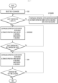
- FIG. 7 is a flowchart showing a method for controlling cleaning of a cooking appliance according to Present Example 1.
- the temperature increasing step (S200) may include a first step (S210) and a second step (S220).
- the internal temperature of the cavity 100 may be increased to a first temperature T1, which is set to a temperature lower than the second temperature T2.
- the first temperature T1 is the oxidation temperature TC of the organic matter.
- the oxidation temperature TC of the organic matter may vary depending on the temperature increase rate of the cavity 100 and may also vary depending on the type of organic matter. Therefore, realistically, the first temperature T1 is not able to be set equal to the oxidation temperature TC of the organic matter.
- a temperature close to the oxidation temperature TC of the organic matter may be set as the first temperature T1.
- the first temperature T1 may be set to 250°C, but the present disclosure may not be limited thereto.
- the internal temperature of the cavity 100 may be increased to reach the second temperature T2 from the first temperature T1.
- a temperature increase rate inside the cavity 100 in the first step (S210) may be set higher than a temperature increase rate inside the cavity 100 in the second step (S220).
- the temperature of the cavity 100 may be increased relatively quickly up to the first temperature T1, which is close to the oxidation temperature TC of the organic matter, and the temperature increase rate may be reduced when the first temperature T1 is reached.
- the removal effect of the organic matter may be increased by increasing the time from the time point at which the oxidation reaction of the organic matter occurs to the time point of reaching the second temperature T2, and thus increasing the time during which the oxidation reaction of the organic matter occurs.
- a heat generation amount of the heater in the first step (S210) may be relatively great, and a heat generation amount of the heater in the second step (S220) may be relatively small.
- the outer heater 220 may operate continuously, and the inner heater 210 and the bake heater 300 may operate in a continuous manner and operate alternately with each other.
- the cooking appliance may have the plurality of heaters, and in the second step (S220), there may be a time period in which some of the plurality of heaters operating in the first step (S210) do not operate.
- the outer heater 220 may operate continuously, and the inner heater 210 and the bake heater 300 may operate alternately, but there may be a time period in which both the inner heater 210 and the bake heater 300 do not operate.
- the inner heater 210 and the bake heater 300 may operate alternately for 30 seconds each for a total of 60 seconds to increase the temperature of the cavity 100.
- the inner heater 210 and the bake heater 300 may operate alternately for 15 seconds each for a total of 30 seconds to increase the temperature of the cavity 100. That is, in the second step (S220), the inner heater 210 and the bake heater 300 may operate for only 30 seconds out of 60 seconds and may not operate for the remaining 30 seconds.
- the temperature increase rate of the cavity 100 may be higher in the first step (S210) and lower in the second step (S220).
- the outer heater 220 may operate continuously, and the inner heater 210 and the bake heater 300 may operate in a continuous manner and operate alternately with each other.
- the inner heater 210 and the bake heater 300 may operate alternately for 30 seconds each for 60 seconds to maintain the temperature of the cavity 100 at the second temperature T2.
- the temperature maintaining step (S300) when the temperature of the cavity 100 exceeds the second temperature T2, at least one of the bake heater 300, the inner heater 210, and the outer heater 220 may stop operating, thereby maintaining the temperature of the cavity 100 at the second temperature T2.
- FIG. 8 is a flowchart showing a method for controlling cleaning of a cooking appliance according to Present Example 2.
- the self-clean mode may proceed in Present Example 2 with the outer heater 220 not operating. Specifically, it is as follows.
- the outer heater 220 may not operate, and the inner heater 210 and the bake heater 300 may operate in a continuous manner and operate alternately with each other.
- the inner heater 210 and the bake heater 300 may operate alternately for 30 seconds each for 60 seconds.
- the outer heater 220 may not operate, and the inner heater 210 and the bake heater 300 may operate alternately, but there may be a time period in which both the inner heater 210 and the bake heater 300 do not operate.
- the inner heater 210 and the bake heater 300 may operate alternately for 15 seconds each for a total of 30 seconds to increase the temperature of the cavity 100. That is, in the second step (S220), the inner heater 210 and the bake heater 300 may operate for only 30 seconds out of 60 seconds and may not operate for the remaining 30 seconds.
- the temperature increase rate of the cavity 100 may be higher in the first step (S210) and lower in the second step (S220) in such scheme.
- the outer heater 220 may not operate, and the inner heater 210 and the bake heater 300 may operate in a continuous manner and operate alternately with each other.
- the inner heater 210 and the bake heater 300 may operate alternately for 30 seconds each for 60 seconds to maintain the temperature of the cavity 100 at the second temperature T2.
- At least one of the bake heater 300 and the inner heater 210 may stop operating to maintain the temperature of the cavity 100 at the second temperature T2.
- the power consumption may be effectively reduced in proceeding the self-clean mode by not using the outer heater 220 in the self-clean mode.
- FIG. 9 is a flowchart showing a method for controlling cleaning of a cooking appliance according to Present Example 3.
- the temperature increasing step (S200) may not be divided into the first step (S210) and the second step (S220) described above in Present Example 3 and in Present Example 4.
- the outer heater 220 may operate continuously, the inner heater 210 and the bake heater 300 may operate in a continuous manner and operate alternately with each other, and an operation time of the bake heater 300 may be set larger than that of the inner heater 210. For example, while the outer heater 220 operates for 60 seconds, the inner heater 210 may operate for 20 seconds and the bake heater 300 may operate for 40 seconds in the alternate manner.
- the inner heater 210 may directly apply the radiant heat to the cavity 100.
- the bake heater 300 may apply the heat to the cavity 100 via the processes of radiation, conduction, and radiation. Therefore, the bake heater 300 may have a more complicated heat transfer path compared to the inner heater 210, thereby heating the cavity 100 slowly.
- the controller may increase the operation time of the bake heater 300 to be greater than that of the inner heater 210 to reduce the temperature increase rate of the cavity 100, thereby controlling the temperature increase rate of the cavity 100 at the set value in the temperature increasing step (S200).
- the outer heater 220 may operate continuously, the inner heater 210 and the bake heater 300 may operate in a continuous manner and operate alternately with each other, and the operation time of the bake heater 300 may be set larger than that of the inner heater 210.
- the temperature maintaining step (S300) may heat the cavity 100 in the same way as the temperature increasing step (S200). However, in the temperature maintaining step (S300), when the temperature of the cavity 100 exceeds the second temperature T2, at least one of the bake heater 300, the inner heater 210, and the outer heater 220 may stop operating to maintain the temperature of the cavity 100 at the second temperature T2.
- FIG. 10 is a flowchart showing a method for controlling cleaning of a cooking appliance according to Present Example 4. Unlike Present Example 3, Present Example 4 may proceed the self-clean mode with the outer heater 220 not operating.
- the outer heater 220 may not operate, the inner heater 210 and the bake heater 300 may operate in a continuous manner and operate alternately with each other, and the operation time of the bake heater 300 may be set larger than that of the inner heater 210.
- the inner heater 210 may operate for 20 seconds and the bake heater 300 may operate for 40 seconds alternately to increase the temperature of the cavity 100.
- the outer heater 220 may not operate, the inner heater 210 and the bake heater 300 may operate in a continuous manner and operate alternately with each other, and the operation time of the bake heater 300 may be set larger than that of the inner heater 210.
- the temperature maintaining step (S300) may heat the cavity 100 in the same way as the temperature increasing step (S200). However, when the temperature of the cavity 100 exceeds the second temperature T2 in the temperature maintaining step (S300), at least one of the bake heater 300 and the inner heater 210 may stop operating to maintain the temperature of the cavity 100 at the second temperature T2.
- the power consumption may be effectively reduced in proceeding the self-clean mode by not using the outer heater 220 in the self-clean mode.
- Present Examples 3 and 4 may maintain the temperature increase rate of the cavity 100 approximately uniformly in the temperature increasing step (S200), thereby effectively lowering the oxidation temperature TC of the organic matter and effectively increasing the thermal decomposition amount compared to Present Examples 1 and 2.
- FIG. 11 is a graph to illustrate the temperature change of the cavity 100 in the temperature increasing step (S200) in Present Example 1 or 2.
- FIG. 12 is a graph to illustrate the temperature change of the cavity 100 in the temperature increasing step (S200) in Present Example 3 or 4.
- FIG. 13 is a graph to illustrate the temperature change of the cavity 100 according to each present example throughout the processes of the self-clean mode.
- a graph (A) is a graph showing a temperature change of the cavity 100 in Comparative Example in which the cavity 100 was heated using all of the inner heater 210, the outer heater 220, and the bake heater 300 in succession.
- a graph (B) is a graph showing the temperature change of the cavity 100 in Present Example 1 or 2.
- a graph (C) is a graph showing the temperature change of the cavity 100 in Present Example 3 or 4.
- a graph (D) is obtained by increasing the temperature of the cavity 100 by Present Example 1 or 2 in the temperature increasing step (S200) and maintaining the temperature of the cavity 100 by Present Example 3 or 4 in the temperature maintaining step (S300).
- the temperature increase rates or temperature increase percentages of Comparative Example and Present Example 1 are similar to each other up to the first step (S210) in which the temperature of the cavity 100 increases to the first temperature T1 in Present Example 1 or Present Example 2. This is because the cavity 100 is heated with an intention of a rapid temperature increase to the first temperature T1 in Present Example 1.
- the temperature increase rate in Present Example 1 or 2 is significantly lower than that in Comparative Example. Accordingly, the thermal decomposition amount of the organic matter may increase in Present Examples 1 and 2 compared to that in Comparative Example.
- the temperature increase rate in Present Example 3 or 4 is lower than that in Comparative Example, and a time it takes to reach the second temperature T2 is larger than that in Comparative Example.
- the thermal decomposition amount of the organic matter may increase compared to that in Comparative Example because of the lower temperature increase rate and the larger temperature increase time compared to those in Comparative Example.
- the thermal decomposition amount of the organic matter may be increased because of the low temperature increase rate and the large temperature increase time.
- FIG. 14 is a graph to illustrate an effect of a method for controlling cleaning of a cooking appliance according to Present Example. An experiment was conducted to identify the effect of the method for controlling the cleaning of the cooking appliance according to Present Example.
- FIG. 14 shows the number of stains remaining on the bottom plate 410 for each case.
- Case 1 proceeded the self-clean mode by setting the second temperature T2 to 430°C and setting the temperature increase rate of the temperature increasing step (S200) to 20°C/min.
- Case 2 proceeded the self-clean mode by setting the second temperature T2 to 440°C and setting the temperature increase rate of the temperature increasing step (S200) to 10°C/min.
- the method for controlling the cleaning of the cooking appliance according to the embodiment consumes the less power and has the better removal effect of the organic matter compared to other methods.
- the temperature increase rate of the cavity 100 may decrease in the temperature increasing step (S200). Therefore, while proceeding the self-clean mode, the time for which the temperature of the cavity 100 is maintained at the second temperature T2, which is a maximum temperature, may be reduced.
- a total heating amount inside the cooking appliance may decrease while proceeding the self-clean mode.
- the overheating of the cooking appliance may be suppressed, thereby effectively preventing the fire from occurring in electrical devices and other combustible components disposed in the cooking appliance.
Landscapes
- Engineering & Computer Science (AREA)
- Chemical & Material Sciences (AREA)
- Combustion & Propulsion (AREA)
- Mechanical Engineering (AREA)
- General Engineering & Computer Science (AREA)
- Chemical Kinetics & Catalysis (AREA)
- Cookers (AREA)
- Electric Stoves And Ranges (AREA)
- Baking, Grill, Roasting (AREA)
Abstract
Description
- The present disclosure relates to a method for controlling cleaning of a cooking appliance, and more particularly, to a method for controlling cleaning of a cooking appliance that is used in a removal process of organic matter in a thermal decomposition scheme.
- A cooking appliance, one of home appliances, has a cavity that accommodates food to be cooked therein. The cavity is defined as a space by panels.
- The cooking appliance is equipped with the cavity and a heating device to heat the food. There may be a plurality of heating devices, and each heating device may heat air and the food in the cavity via conduction, convection, or radiation.
- During a cooking process, the cavity and the food are heated at a high temperature, so that organic matter contained in the food may splash or spill into the cavity. In the high-temperature environment, the organic matter from the food may be attached to a surface of the panel constituting the cavity.
- For hygiene and aesthetics and for maintaining a function of the cooking appliance, it is necessary to remove the organic matter attached to the surface of the panel. The cooking appliance may have a self-clean function to remove such organic matter on its own.
- The self-clean is a separate function that is distinct from a cooking function of the cooking appliance. The cooking appliance may operate a self-clean mode when not performing the cooking to remove the organic matter attached to the panel.
- The self-clean involves operating the heating device equipped in the cooking appliance to heat the cavity at the high temperature to thermally decompose and remove the organic matter attached to the surface of the panel. The organic matter may react with oxygen in air at the high temperature and be oxidized, and thus be separated and removed from the panel.
- During the thermal decomposition process, the lower the oxidation temperature at which the organic matter reacts with oxygen in air, the easier the thermal decomposition of the organic matter may occur. Additionally, as a thermal decomposition amount of the organic matter increases during the thermal decomposition process, the organic matter may be effectively removed.
- Therefore, it is necessary to identify what factors may decrease the oxidation temperature and increase the thermal decomposition amount of the organic matter in the self-clean mode.
- There is a need to identify such factors and develop a method for controlling cleaning of the cooking appliance that may increase the removal effect of the organic matter based on such factors.
- The present disclosure is to provide a method for controlling cleaning of a cooking appliance that has a structure that may easily remove organic matter attached to a panel constituting a cavity.
- Additionally, the present disclosure is to provide a method for controlling cleaning of a cooking appliance that has a structure that may lower an oxidation temperature of organic matter and increase a thermal decomposition amount in a self-clean mode.
- Additionally, the present disclosure is to provide a method for controlling cleaning of a cooking appliance that controls a temperature increase rate of a cavity to lower an oxidation temperature of organic matter and increase a thermal decomposition amount in a self-clean mode.
- Purposes according to the present disclosure are not limited to the above-mentioned purpose. Other purposes and advantages according to the present disclosure that are not mentioned may be understood based on following descriptions, and may be more clearly understood based on embodiments according to the present disclosure. Further, it will be easily understood that the purposes and advantages according to the present disclosure may be realized using means shown in the claims or combinations thereof.
- The present invention is defined by the independent claims; the dependent claims describe embodiments of the present invention.
- An embodiment of a method for controlling cleaning of a cooking appliance includes a mode selecting step of selecting a self-clean mode of a cavity, a temperature increasing step of increasing an internal temperature of the cavity to a set second temperature, and a temperature maintaining step of maintaining the internal temperature of the cavity at the second temperature. The temperature increasing step includes controlling a temperature increase rate inside the cavity in the temperature increasing step by operating a broil heater and a bake heater alternately.
- An oxidation temperature of organic matter may be lowered and a thermal decomposition amount of the organic matter may be increased by controlling the temperature increase rate inside the cavity.
- The temperature increasing step may include a first step of increasing the internal temperature of the cavity to a first temperature, and a second step of increasing the internal temperature of the cavity to reach the second temperature from the first temperature. A temperature increase rate inside the cavity in the first step may be set higher than a temperature increase rate inside the cavity in the second step. Accordingly, a removal effect of the organic matter may be improved by increasing a time during which an oxidation reaction of the organic matter occurs.
- In the temperature increasing step, the outer heater may operate continuously, the inner heater and the bake heater may operate in a continuous manner and operate alternately with each other, and an operation time of the bake heater may be set larger than an operation time of the inner heater. Accordingly, the temperature increase rate of the cavity may be maintained approximately uniformly in the temperature increasing step.
- In the temperature increasing step, the outer heater may not operate, and the inner heater and the bake heater may operate in a continuous manner and operate alternately with each other to increase the temperature of the cavity. Accordingly, power consumption resulted from the heater operation in the temperature increasing step may be reduced.
- A cooking appliance according to an embodiment includes a cavity where food to be cooked is accommodated, a broil heater that applies radiant heat to the cavity, and a bake heater that heats a panel constituting the cavity.
- A method for controlling cleaning of a cooking appliance according to an embodiment includes a mode selecting step of selecting a self-clean mode of a cavity, a temperature increasing step of increasing an internal temperature of the cavity to a set second temperature, and a temperature maintaining step of maintaining the internal temperature of the cavity at the second temperature. The temperature increasing step includes controlling a temperature increase rate inside the cavity in the temperature increasing step by operating a broil heater and a bake heater alternately.
- The broil heater may include an inner heater disposed at an upper portion of the cavity, and an outer heater disposed at the upper portion of the cavity to surround the inner heater, wherein the outer heater has an output lower than an output of the inner heater.
- The temperature increasing step may include alternately operating the inner heater and the bake heater to control the temperature increase rate inside the cavity.
- The temperature increasing step may include a first step of increasing the internal temperature of the cavity to a first temperature set lower than the second temperature, and a second step of increasing the internal temperature of the cavity to reach the second temperature from the first temperature.
- A temperature increase rate inside the cavity in the first step may be set higher than a temperature increase rate inside the cavity in the second step.
- In the first step, the outer heater may operate continuously, and the inner heater and the bake heater may operate in a continuous manner and operate alternately with each other. In the second step, the outer heater may operate continuously, and the inner heater and the bake heater may operate alternately with each other, but there may be a time period where both the inner heater and the bake heater do not operate.
- In the temperature maintaining step, the outer heater may operate continuously, and the inner heater and the bake heater may operate in a continuous manner and operate alternately with each other.
- In the first step, the outer heater may not operate, and the inner heater and the bake heater may operate in a continuous manner and operate alternately with each other. In the second step, the outer heater may not operate, and the inner heater and the bake heater may operate alternately with each other, but there may be a time period where both the inner heater and the bake heater do not operate.
- In the temperature maintaining step, the outer heater may not operate, and the inner heater and the bake heater may operate in a continuous manner and operate alternately with each other.
- In the temperature increasing step, the outer heater may operate continuously, the inner heater and the bake heater may operate in a continuous manner and operate alternately with each other, and an operation time of the bake heater may be set larger than an operation time of the inner heater.
- In the temperature maintaining step, the outer heater may operate continuously, the inner heater and the bake heater may operate in a continuous manner and operate alternately with each other, and an operation time of the bake heater may be set larger than an operation time of the inner heater.
- In the temperature increasing step, the outer heater may not operate, the inner heater and the bake heater may operate in a continuous manner and operate alternately with each other, and an operation time of the bake heater may be set larger than an operation time of the inner heater.
- In the temperature maintaining step, the outer heater may not operate, the inner heater and the bake heater may operate in a continuous manner and operate alternately with each other, and an operation time of the bake heater may be set larger than an operation time of the inner heater.
- A cooking appliance according to another embodiment includes a cavity where food to be cooked is accommodated, an inner heater disposed at an upper portion of the cavity, and an outer heater disposed at the upper portion of the cavity to surround the inner heater, wherein the outer heater has an output lower than an output of the inner heater. The cooking appliance includes a bake heater that heats a panel constituting the cavity.
- A method for controlling cleaning of a cooking appliance according to another embodiment includes a temperature increasing step of increasing an internal temperature of a cavity to a set second temperature, and a temperature maintaining step of maintaining the internal temperature of the cavity at the second temperature. The temperature increasing step includes a first step of increasing the internal temperature of the cavity to a first temperature set lower than the second temperature, and a second step of increasing the internal temperature of the cavity to reach the second temperature from the first temperature. A temperature increase rate inside the cavity in the first step is set higher than a temperature increase rate inside the cavity in the second step.
- In the first step, the outer heater may operate continuously, and the inner heater and the bake heater may operate in a continuous manner and operate alternately with each other. In the second step, the outer heater may operate continuously, and the inner heater and the bake heater may operate alternately with each other, but there may be a time period where both the inner heater and the bake heater do not operate. In the temperature maintaining step, the outer heater may operate continuously, and the inner heater and the bake heater may operate in a continuous manner and operate alternately with each other.
- A method for controlling cleaning of a cooking appliance according to another embodiment includes a cavity where food to be cooked is accommodated, a heater that heats the interior of the cavity, and a controller that controls the heater. The method includes a temperature increasing step of increasing an internal temperature of the cavity to a set second temperature, and a temperature maintaining step of maintaining the internal temperature of the cavity at the second temperature.
- The temperature increasing step may include a first step of increasing the internal temperature of the cavity to a first temperature set lower than the second temperature, and a second step of increasing the internal temperature of the cavity to reach the second temperature from the first temperature. A temperature increase rate inside the cavity in the first step may be set higher than a temperature increase rate inside the cavity in the second step.
- The heater may include a plurality of heaters, and in the second step, there may be a time period where some of the plurality of heaters operating in the first step do not operate.
- The heater may include an inner heater disposed at an upper portion of the cavity, an outer heater disposed at the upper portion of the cavity to surround the inner heater, wherein the outer heater has an output lower than an output of the inner heater, and a bake heater that heats a panel constituting the cavity. The temperature increasing step may include controlling the temperature increase rate inside the cavity by operating the inner heater and the bake heater alternately.
- In the first step, the outer heater may operate continuously, and the inner heater and the bake heater may operate in a continuous manner and operate alternately with each other. In the second step, the outer heater may operate continuously, and the inner heater and the bake heater may operate alternately with each other, but there may be a time period where both the inner heater and the bake heater do not operate.
- In the first step, the outer heater may not operate, and the inner heater and the bake heater may operate in a continuous manner and operate alternately with each other. In the second step, the outer heater may not operate, and the inner heater and the bake heater may operate alternately with each other, but there may be a time period where both the inner heater and the bake heater do not operate.
- In the temperature maintaining step, the outer heater may operate continuously, and the inner heater and the bake heater may operate in a continuous manner and operate alternately with each other.
- A method for controlling cleaning of a cooking appliance according to another embodiment includes a temperature increasing step of increasing an internal temperature of a cavity to a set second temperature, and a temperature maintaining step of maintaining the internal temperature of the cavity at the second temperature. In the temperature increasing step and the temperature maintaining step, the inner heater and the bake heater operate in a continuous manner and operate alternately with each other, and an operation time of the bake heater is set larger than an operation time of the inner heater.
- In the method for controlling the cleaning of the cooking appliance according to the present disclosure, the temperature of the cavity may be increased relatively quickly up to the first temperature that is close to the oxidation temperature of the organic matter, and the temperature increase rate may be reduced when the first temperature is reached.
- Accordingly, the removal effect of the organic matter may be increased by increasing the time from the time point at which the oxidation reaction of the organic matter occurs to the time point of reaching the second temperature, and thus increasing the time during which the oxidation reaction of the organic matter occurs.
- Further, in the method for controlling the cleaning of the cooking appliance according to the present disclosure, the oxidation temperature of the organic matter may be effectively lowered and the thermal decomposition amount may be effectively increased by maintaining the temperature increase rate of the cavity approximately uniformly in the temperature increasing step.
- Further, in the method for controlling the cleaning of the cooking appliance according to the present disclosure, the temperature increase rate of the cavity may decrease in the temperature increasing step. Therefore, while proceeding the self-clean mode, the time for which the temperature of the cavity is maintained at the second temperature, which is the maximum temperature, may be reduced.
- Therefore, the total heating amount inside the cooking appliance may decrease while proceeding the self-clean mode. As a result, the overheating of the cooking appliance may be suppressed, thereby effectively preventing the fire from occurring in the electrical devices and other combustible components disposed in the cooking appliance.
- In addition to the above-mentioned effects, specific effects of the present disclosure will be described below while describing the specific details for carrying out the invention.
-
-
FIG. 1 is a diagram schematically showing a cooking appliance according to an embodiment. -
FIG. 2 is a view of a ceiling plate from inside a cavity of a cooking appliance according to an embodiment. -
FIG. 3 is a rear view from inside a cavity of a cooking appliance according to an embodiment. -
FIG. 4 is a view of a bottom plate from inside a cavity of a cooking appliance according to an embodiment. -
FIG. 5 is a graph to illustrate a temperature increase rate and a thermal decomposition amount of an experimental material. -
FIG. 6 is a graph showing a temperature increase rate and an oxidation temperature TC of an experimental material. -
FIG. 7 is a flowchart showing a method for controlling cleaning of a cooking appliance according to Present Example 1. -
FIG. 8 is a flowchart showing a method for controlling cleaning of a cooking appliance according to Present Example 2. -
FIG. 9 is a flowchart showing a method for controlling cleaning of a cooking appliance according to Present Example 3. -
FIG. 10 is a flowchart showing a method for controlling cleaning of a cooking appliance according to Present Example 4. -
FIG. 11 is a graph to illustrate a temperature change of a cavity in a temperature increasing step in Present Example 1 or 2. -
FIG. 12 is a graph to illustrate a temperature change of a cavity in a temperature increasing step in Present Example 3 or 4. -
FIG. 13 is a graph to illustrate a temperature change of a cavity according to each present example throughout processes of a self-clean mode. -
FIG. 14 is a graph to illustrate an effect of a method for controlling cleaning of a cooking appliance according to Present Example. - The above-mentioned purposes, features, and advantages will be described in detail later with reference to the attached drawings, so that those skilled in the art in the technical field to which the present disclosure belongs may easily practice the technical ideas of the present disclosure. In describing the present disclosure, when it is determined that a detailed description of the publicly known technology related to the present disclosure may unnecessarily obscure the gist of the present disclosure, the detailed description thereof will be omitted. Hereinafter, a preferred embodiment according to the present disclosure will be described in detail with reference to the attached drawings. In the drawings, identical reference numerals are used to indicate identical or similar components.
- It will be understood that, although the terms "first", "second", "third", and so on may be used herein to describe various elements, components, regions, layers and/or sections, these elements, components, regions, layers and/or sections should not be limited by these terms. These terms are used to distinguish one element, component, region, layer or section from another element, component, region, layer or section. Thus, a first element, component, region, layer or section described under could be termed a second element, component, region, layer or section, without departing from the scope of the present disclosure.
- As used herein, the singular constitutes "a" and "an" are intended to include the plural constitutes as well, unless the context clearly indicates otherwise.
- It will be further understood that the terms "comprise", "comprising", "include", and "including" when used in this specification, specify the presence of the stated features, integers, operations, elements, and/or components, but do not preclude the presence or addition of one or more other features, integers, operations, elements, components, and/or portions thereof.
- Throughout the present disclosure, "A and/or B" means A, B, or A and B, unless otherwise specified, and "C to D" means C inclusive to D inclusive unless otherwise specified.
- Throughout the present document, "up, down, front, rear" refers to a location of a cooking appliance when the cooking appliance is installed for daily use. Additionally, throughout the present document, a "vertical direction" refers to a vertical direction of the cooking appliance when the cooking appliance is installed for daily use. A "left and right direction" refers to a direction perpendicular to the vertical direction, and a front and rear direction refers to a direction perpendicular to both the vertical direction and the left and right direction. A "lateral direction" may have the same meaning as the left and right direction, and these terms may be used interchangeably herein.
-
FIG. 1 is a diagram schematically showing a cooking appliance according to an embodiment. The cooking appliance may include acavity 100, which is a space in which food to be cooked is accommodated. The food to be cooked may be placed in thecavity 100 and may be heated at a high temperature. - The cooking appliance may have a
panel 400 to define thecavity 100. Thepanel 400 may be open at a front side facing a door and may include a side plate, abottom plate 410, and aceiling plate 420. The side plate may form a side wall of thecavity 100, thebottom plate 410 may form a bottom of thecavity 100, and theceiling plate 420 may form a ceiling of thecavity 100. - The food placed in the
cavity 100 may be heated in a high-temperature environment. To this end, the cooking appliance may be equipped with a heater to heat thecavity 100. - When the food is heated, some of organic matter contained in the food may be attached to an inner wall of the
panel 400, which constitutes thecavity 100. When the organic matter attached to thepanel 400 is left as is, hygiene problems will arise, so that the organic matter needs to be removed periodically. - To remove the organic matter attached to the
panel 400, thecavity 100 may be heated using the heater disposed in the cooking appliance, so that the organic matter may be removed via thermal decomposition. A reaction formula for the thermal decomposition is as follows.
organic matter + O2 + heat → CO + H2 + CmHn + ash
- In other words, when heat is applied to the organic matter, the organic matter may react with oxygen in air and be oxidized, so that carbon monoxide, hydrogen, hydrocarbon, and ash may be generated as products of the oxidation of the organic matter. Carbon monoxide and hydrogen go into air, and hydrocarbon and ash fall from a surface of the
panel 400, so that the organic matter attached to thepanel 400 may be removed. - To apply heat to the organic matter attached to the
panel 400, thecavity 100 may be heated at the high temperature, for example, at a temperature equal to or higher than approximately 400°C. The heating of thecavity 100 may be carried out by the heater disposed in the cooking appliance. - Such organic matter removal process using the thermal decomposition scheme may be carried out separately from a cooking process of the cooking appliance. A method for controlling cleaning of a cooking appliance according to an embodiment relates to a method for controlling cleaning of a cooking appliance used in the removal process of the organic matter using the thermal decomposition scheme.
- Hereinafter, the heater disposed in the cooking appliance will be described.
FIG. 2 is a view of theceiling plate 420 from inside thecavity 100 of the cooking appliance according to an embodiment.FIG. 3 is a rear view from inside thecavity 100 of the cooking appliance according to an embodiment.FIG. 4 is a view of thebottom plate 410 from inside thecavity 100 of the cooking appliance according to an embodiment. - The cooking appliance may include a
broil heater 200, abake heater 300, and aconvection heater 500. Such heaters may be operated via, for example, an electric resistance heating scheme. - The
broil heater 200 may apply radiant heat to thecavity 100. For example, thebroil heater 200 may be disposed at an upper portion of thecavity 100, that is, at a location adjacent to theceiling plate 420 of thepanel 400, and may be equipped as a heating tube and heated to heat air in thecavity 100 by applying the radiant heat to thecavity 100. - The
bake heater 300 may heat thepanel 400 constituting thecavity 100. For example, thebake heater 300 may be disposed under thebottom plate 410 of thepanel 400 and disposed outside thecavity 100. Thebake heater 300 may be equipped as a plate-shaped heating element or a heating tube and apply the radiant heat to thebottom plate 410. - The heat from the
bottom plate 410 heated by thebake heater 300 may be transferred to an entirety of thepanel 400 via conduction. Thepanel 400 heated as such may apply the radiant heat to thecavity 100. Therefore, thebake heater 300 may heat air in thecavity 100 by transferring the heat sequentially via radiation, conduction, and radiation. - The
convection heater 500 may be disposed at a rear portion of thecavity 100 to extend through thepanel 400, and may include afan 510 and aconvection heating unit 520. Theconvection heating unit 520 may be equipped as a heating tube and be heated. Thefan 510 may be disposed in front of theconvection heating unit 520 and operate to circulate air inside thecavity 100. Accordingly, the heat of theconvection heating unit 520 may heat air in thecavity 100 via convection. - In the typical food cooking process, the
convection heater 500 disposed in the cooking appliance may operate to cook the food. However, in the method for controlling the cleaning of the cooking appliance used in the organic matter removal process according to the embodiment, theconvection heating unit 520 of theconvection heater 500 may not operate. - In the method for controlling the cleaning of the cooking appliance according to the embodiment, when the
cavity 100 is heated using all of the three types of heaters, a temperature increase rate inside thecavity 100 is excessively high, so that thecavity 100 may be heated using thebroil heater 200 and thebake heater 300 without using theconvection heating unit 520, which is not suitable for controlling the temperature increase rate inside thecavity 100 in the embodiment. - However, to effectively remove the organic matter, it is necessary to distribute the heat evenly inside the
cavity 100, so that thefan 510 may be operated during the organic matter removal process. In conclusion, in the method for controlling the cleaning of the cooking appliance for removing the organic matter according to the embodiment, thefan 510, thebroil heater 200, and thebake heater 300 may operate. - To effectively remove the organic matter attached to the
panel 400, the lower the oxidation temperature TC, which is a temperature at which the organic matter reacts with oxygen in air and is oxidized, the more advantageous it is. This is because, as the oxidation temperature TC becomes lower, power becomes less consumed, and when a total time required for the organic matter removal process is the same, an oxidation time of the organic matter becomes larger compared to that in a case in which the oxidation temperature TC is high. - Therefore, it is necessary to find factors that may lower the oxidation temperature TC. In the embodiment, an experiment was conducted to elucidate a relationship between the temperature increase rate of the
cavity 100 and the oxidation temperature TC during the organic matter removal process. - Additionally, in the embodiment, when the temperature of the
cavity 100 is increased to reach a set second temperature T2, the organic matter removal process may be performed in a scheme of maintaining the temperature of thecavity 100 at the second temperature T2. - Therefore, in the experiment, a relationship between a thermal decomposition amount of the organic matter, that is, an amount of the organic matter oxidized by heat, and the temperature increase rate from a time point of the oxidation temperature TC to a time point of reaching the second temperature T2, which is higher than the oxidation temperature, was elucidated together. The greater the thermal decomposition amount of the organic matter, the more effective the organic matter removal is.
- An experimental material used in such experiment is deasphalted oil (DAO), which has a similar composition to the organic matter attached to the inner wall of the
panel 400 of the cooking appliance. In the experiment, while heating the DAO, the temperature increase rate was adjusted and a trend thereof was observed. - Hereinafter, experimental results will be described with reference to
FIGS. 5 and 6. FIG. 5 is a graph to illustrate a temperature increase rate and a thermal decomposition amount of an experimental material.FIG. 6 is a graph showing a temperature increase rate and an oxidation temperature TC of an experimental material. - Referring to
FIG. 5 , a vertical axis of the graph represents a weight of the experimental material in percent, and a horizontal axis represents a temperature of the experimental material. Therefore, the thermal decomposition amount of the experimental material means a weight reduction amount of the experimental material from the time point of the oxidation temperature TC to the time point of reaching the second temperature T2, and is shown as a double arrow inFIG. 5 . - In the experiment, the second temperature T2 was set at 430°C, which is a temperature set in the general organic matter removal process including the present embodiment.
- As the experimental results, relationships between the temperature increase rate, the thermal decomposition amount, and the oxidation temperature TC are as shown in Table 1.
[Table 1] Temperature increase rate (°C/min) Thermal decomposition amount (%) Oxidation temperature TC (°C) 5 69 237 10 58 247 20 50 254 25 43 258 - In
FIG. 6 , the relationship between the temperature increase rate and the oxidation temperature TC according to the experimental results is shown in the graph. - As the experiment results, it may be seen that the lower the temperature increase rate, the lower the oxidation temperature TC. This is determined to be because the lower the temperature increase rate, the smaller the activation energy required for the oxidation reaction, allowing the oxidation reaction of the organic matter to occur even at a relatively low temperature.
- Additionally, as the experiment results, it may be seen that the lower the temperature increase rate, the greater the thermal decomposition amount of the organic matter in the period between the oxidation temperature TC and the second temperature T2. This is determined to be because the lower the temperature increase rate, the smaller the activation energy required for the oxidation reaction, which may accelerate an oxidation reaction rate.
- As the experiment results, it may be seen that the lower the temperature increase rate of the
cavity 100, the lower the oxidation temperature TC of the organic matter and the greater the thermal decomposition amount before reaching the second temperature T2, which is advantageous in removing the organic matter. - However, when the temperature increase rate is excessively low, it may take a long time to reach the second temperature T2, and the total time required for the organic matter removal process may be large. When such total time is kept the same, a time for which the
cavity 100 is maintained at the second temperature T2 may decrease, deteriorating the organic matter removal effect. - Therefore, to increase the organic matter removal effect, it is necessary to appropriately adjust the temperature increase rate. The embodiment presents a method for controlling cleaning of a cooking appliance that controls the temperature increase rate inside the
cavity 100 to increase the organic matter removal effect. - The embodiment is the method for controlling the cleaning of the cooking appliance for the process of removing the organic matter attached to the
panel 400, which is carried out separately from the cooking process. The specific control to be described below may be performed by a controller disposed in the cooking appliance and controlling the operation of each heater. - The method for controlling the cleaning of the cooking appliance according to the embodiment may include a mode selecting step (S100), a temperature increasing step (S200), and a temperature maintaining step (S300). In the mode selecting step (S100), the self-clean mode of the
cavity 100 may be selected. - The self-clean mode is a function of the cooking appliance that removes the organic matter attached to the
panel 400 on its own. The self-clean mode may be selected by receiving, by the controller, a user's command. In another embodiment, the selection of the self-clean mode may be performed periodically by the controller itself at set date and time without the command input from the user. - When the self-clean mode is in progress, the controller may sequentially proceed with the temperature increasing step (S200) and the temperature maintaining step (S300). In the temperature increasing step (S200), the internal temperature of the
cavity 100 may be increased to the set second temperature T2. The second temperature T2 may be set to, for example, 430°C, but the present disclosure may not be limited thereto. - In the temperature maintaining step (S300), the internal temperature of the
cavity 100 may be maintained at the second temperature T2. The self-clean mode may end after a time set in the temperature maintaining step (S300) elapses. The set time, as a total time required for the self-clean mode to proceed, may be, for example, 2 hours, but the present disclosure may not be limited thereto. - In the temperature increasing step (S200), operation of the heaters may be controlled to control the temperature increase rate of the
cavity 100 at a set value. When all of the heaters are operated simultaneously, the temperature increase rate of thecavity 100 becomes very high and thus is not able to be controlled at a desired rate. - Therefore, in the temperature increasing step (S200), the
broil heater 200 and thebake heater 300 may be operated alternately to control the temperature increase rate inside thecavity 100 in the temperature increasing step (S200). In the temperature increasing step (S200), the temperature increase rate of thecavity 100 may be controlled by operating thebroil heater 200 and thebake heater 300 alternately to reduce an amount of heat applied to thecavity 100. - As shown in
FIG. 2 , thebroil heater 200 may include aninner heater 210 and anouter heater 220. Theinner heater 210 may be disposed at the upper portion of thecavity 100. - The
outer heater 220 may be disposed at the upper portion of thecavity 100 to surround theinner heater 210, and may have a lower output than theinner heater 210. Theouter heater 220 may be disposed in a wider range in thecavity 100 than theinner heater 210. - Therefore, the
outer heater 220 may apply the radiant heat to a wider area of thecavity 100 compared to theinner heater 210, so that theouter heater 220 may produce the same temperature increase effect in thecavity 100 as theinner heater 210 with an output smaller than that of theinner heater 210. - For example, for the same temperature increase of the
cavity 100, when theinner heater 210 requires an output of 1600W, theouter heater 220 requires an output of 1500W. Therefore, it may be appropriate in terms of energy efficiency to use the more efficientouter heater 220 continuously and use the less efficientinner heater 210 discontinuously to perform the self-clean. - Therefore, in the temperature increasing step (S200), the temperature increase rate inside the
cavity 100 may be controlled by operating theinner heater 210 and thebake heater 300 alternately. Likewise, also in the temperature maintaining step (S300), the temperature inside thecavity 100 may be maintained at the second temperature T2 by operating theinner heater 210 and thebake heater 300 alternately. - However, depending on the embodiment, power consumption required to operate the heaters may be reduced by operating only the
inner heater 210 and thebake heater 300 alternately instead of using theouter heater 220 in the temperature increasing step (S200) or in the temperature maintaining step (S300). - Hereinafter, the method for controlling the cleaning of the cooking appliance will be described in detail for each present example. In each present example below, the second temperature T2 may be set to, for example, 430°C, but the present disclosure may not be limited thereto.
- Additionally, the set time of the self-clean mode in each present example may be, for example, 2 hours, but the present disclosure may not be limited thereto. The set time may refer to the total time required for the self-clean mode to proceed, and the controller may end the self-clean mode when an operation time of the self-clean mode of the cooking appliance reaches the set time.
- Hereinafter, 'for 60 seconds' describes a unit time and does not mean that the total time required for each step is only 60 seconds.
-
FIG. 7 is a flowchart showing a method for controlling cleaning of a cooking appliance according to Present Example 1. In Present Example 1 and Present Example 2, the temperature increasing step (S200) may include a first step (S210) and a second step (S220). - In the first step (S210), the internal temperature of the
cavity 100 may be increased to a first temperature T1, which is set to a temperature lower than the second temperature T2. Ideally, it may be appropriate that the first temperature T1 is the oxidation temperature TC of the organic matter. - However, as described above, the oxidation temperature TC of the organic matter may vary depending on the temperature increase rate of the
cavity 100 and may also vary depending on the type of organic matter. Therefore, realistically, the first temperature T1 is not able to be set equal to the oxidation temperature TC of the organic matter. - Therefore, a temperature close to the oxidation temperature TC of the organic matter may be set as the first temperature T1. For example, the first temperature T1 may be set to 250°C, but the present disclosure may not be limited thereto.
- In the second step (S220), the internal temperature of the
cavity 100 may be increased to reach the second temperature T2 from the first temperature T1. - A temperature increase rate inside the
cavity 100 in the first step (S210) may be set higher than a temperature increase rate inside thecavity 100 in the second step (S220). In the embodiment, the temperature of thecavity 100 may be increased relatively quickly up to the first temperature T1, which is close to the oxidation temperature TC of the organic matter, and the temperature increase rate may be reduced when the first temperature T1 is reached. - Accordingly, the removal effect of the organic matter may be increased by increasing the time from the time point at which the oxidation reaction of the organic matter occurs to the time point of reaching the second temperature T2, and thus increasing the time during which the oxidation reaction of the organic matter occurs.
- To this end, a heat generation amount of the heater in the first step (S210) may be relatively great, and a heat generation amount of the heater in the second step (S220) may be relatively small. In the first step (S210), the
outer heater 220 may operate continuously, and theinner heater 210 and thebake heater 300 may operate in a continuous manner and operate alternately with each other. - As described above, the cooking appliance may have the plurality of heaters, and in the second step (S220), there may be a time period in which some of the plurality of heaters operating in the first step (S210) do not operate.
- In the second step (S220), the
outer heater 220 may operate continuously, and theinner heater 210 and thebake heater 300 may operate alternately, but there may be a time period in which both theinner heater 210 and thebake heater 300 do not operate. - Referring to
FIG. 7 , for example, in the first step (S210), while theouter heater 220 operates continuously for 60 seconds, theinner heater 210 and thebake heater 300 may operate alternately for 30 seconds each for a total of 60 seconds to increase the temperature of thecavity 100. - In the second step (S220), while the
outer heater 220 operates continuously for 60 seconds, theinner heater 210 and thebake heater 300 may operate alternately for 15 seconds each for a total of 30 seconds to increase the temperature of thecavity 100. That is, in the second step (S220), theinner heater 210 and thebake heater 300 may operate for only 30 seconds out of 60 seconds and may not operate for the remaining 30 seconds. - In such scheme, the temperature increase rate of the
cavity 100 may be higher in the first step (S210) and lower in the second step (S220). - In the temperature maintaining step (S300), the
outer heater 220 may operate continuously, and theinner heater 210 and thebake heater 300 may operate in a continuous manner and operate alternately with each other. For example, in the temperature maintaining step (S300), while theouter heater 220 operates continuously for 60 seconds, theinner heater 210 and thebake heater 300 may operate alternately for 30 seconds each for 60 seconds to maintain the temperature of thecavity 100 at the second temperature T2. - In one example, in the temperature maintaining step (S300), when the temperature of the
cavity 100 exceeds the second temperature T2, at least one of thebake heater 300, theinner heater 210, and theouter heater 220 may stop operating, thereby maintaining the temperature of thecavity 100 at the second temperature T2. -
FIG. 8 is a flowchart showing a method for controlling cleaning of a cooking appliance according to Present Example 2. Compared to Present Example 1, the self-clean mode may proceed in Present Example 2 with theouter heater 220 not operating. Specifically, it is as follows. - In the first step (S210), the
outer heater 220 may not operate, and theinner heater 210 and thebake heater 300 may operate in a continuous manner and operate alternately with each other. For example, in the first step (S210), theinner heater 210 and thebake heater 300 may operate alternately for 30 seconds each for 60 seconds. - In the second step (S220), the
outer heater 220 may not operate, and theinner heater 210 and thebake heater 300 may operate alternately, but there may be a time period in which both theinner heater 210 and thebake heater 300 do not operate. - For example, in the second step (S220), for 60 seconds, the
inner heater 210 and thebake heater 300 may operate alternately for 15 seconds each for a total of 30 seconds to increase the temperature of thecavity 100. That is, in the second step (S220), theinner heater 210 and thebake heater 300 may operate for only 30 seconds out of 60 seconds and may not operate for the remaining 30 seconds. - As in Present Example 1, in Present Example 2, the temperature increase rate of the
cavity 100 may be higher in the first step (S210) and lower in the second step (S220) in such scheme. - In the temperature maintaining step (S300), the
outer heater 220 may not operate, and theinner heater 210 and thebake heater 300 may operate in a continuous manner and operate alternately with each other. For example, in the temperature maintaining step (S300), theinner heater 210 and thebake heater 300 may operate alternately for 30 seconds each for 60 seconds to maintain the temperature of thecavity 100 at the second temperature T2. - In one example, when the temperature of the
cavity 100 exceeds the second temperature T2 in the temperature maintaining step (S300), at least one of thebake heater 300 and theinner heater 210 may stop operating to maintain the temperature of thecavity 100 at the second temperature T2. - In Present Example 2, the power consumption may be effectively reduced in proceeding the self-clean mode by not using the
outer heater 220 in the self-clean mode. -
FIG. 9 is a flowchart showing a method for controlling cleaning of a cooking appliance according to Present Example 3. Unlike Present Examples 1 and 2, the temperature increasing step (S200) may not be divided into the first step (S210) and the second step (S220) described above in Present Example 3 and in Present Example 4. - In the temperature increasing step (S200), the
outer heater 220 may operate continuously, theinner heater 210 and thebake heater 300 may operate in a continuous manner and operate alternately with each other, and an operation time of thebake heater 300 may be set larger than that of theinner heater 210. For example, while theouter heater 220 operates for 60 seconds, theinner heater 210 may operate for 20 seconds and thebake heater 300 may operate for 40 seconds in the alternate manner. - As described above, the
inner heater 210 may directly apply the radiant heat to thecavity 100. On the other hand, thebake heater 300 may apply the heat to thecavity 100 via the processes of radiation, conduction, and radiation. Therefore, thebake heater 300 may have a more complicated heat transfer path compared to theinner heater 210, thereby heating thecavity 100 slowly. - Therefore, in Present Example 3, the controller may increase the operation time of the
bake heater 300 to be greater than that of theinner heater 210 to reduce the temperature increase rate of thecavity 100, thereby controlling the temperature increase rate of thecavity 100 at the set value in the temperature increasing step (S200). - In the temperature maintaining step (S300), the
outer heater 220 may operate continuously, theinner heater 210 and thebake heater 300 may operate in a continuous manner and operate alternately with each other, and the operation time of thebake heater 300 may be set larger than that of theinner heater 210. - The temperature maintaining step (S300) may heat the
cavity 100 in the same way as the temperature increasing step (S200). However, in the temperature maintaining step (S300), when the temperature of thecavity 100 exceeds the second temperature T2, at least one of thebake heater 300, theinner heater 210, and theouter heater 220 may stop operating to maintain the temperature of thecavity 100 at the second temperature T2. -
FIG. 10 is a flowchart showing a method for controlling cleaning of a cooking appliance according to Present Example 4. Unlike Present Example 3, Present Example 4 may proceed the self-clean mode with theouter heater 220 not operating. - In the temperature increasing step (S200), the
outer heater 220 may not operate, theinner heater 210 and thebake heater 300 may operate in a continuous manner and operate alternately with each other, and the operation time of thebake heater 300 may be set larger than that of theinner heater 210. For example, in the temperature increasing step (S200), for 60 seconds, theinner heater 210 may operate for 20 seconds and thebake heater 300 may operate for 40 seconds alternately to increase the temperature of thecavity 100. - In the temperature maintaining step (S300), the
outer heater 220 may not operate, theinner heater 210 and thebake heater 300 may operate in a continuous manner and operate alternately with each other, and the operation time of thebake heater 300 may be set larger than that of theinner heater 210. - The temperature maintaining step (S300) may heat the
cavity 100 in the same way as the temperature increasing step (S200). However, when the temperature of thecavity 100 exceeds the second temperature T2 in the temperature maintaining step (S300), at least one of thebake heater 300 and theinner heater 210 may stop operating to maintain the temperature of thecavity 100 at the second temperature T2. - In Present Example 4, the power consumption may be effectively reduced in proceeding the self-clean mode by not using the
outer heater 220 in the self-clean mode. - Based on the experimental results, in Present Examples 3 and 4, there is no rapid temperature increase period in the beginning, so that, compared to Present Examples 1 and 2, the oxidation temperature TC of the organic matter may be decreased, and the thermal decomposition amount of the organic matter may be increased in the temperature increasing step (S200).
- Therefore, unlike Present Examples 1 and 2, Present Examples 3 and 4 may maintain the temperature increase rate of the
cavity 100 approximately uniformly in the temperature increasing step (S200), thereby effectively lowering the oxidation temperature TC of the organic matter and effectively increasing the thermal decomposition amount compared to Present Examples 1 and 2. - Hereinafter, the temperature change of the
cavity 100 according to each present example in the self-clean mode will be described with reference to graphs. -
FIG. 11 is a graph to illustrate the temperature change of thecavity 100 in the temperature increasing step (S200) in Present Example 1 or 2.FIG. 12 is a graph to illustrate the temperature change of thecavity 100 in the temperature increasing step (S200) in Present Example 3 or 4.FIG. 13 is a graph to illustrate the temperature change of thecavity 100 according to each present example throughout the processes of the self-clean mode. - In each drawing, a graph (A) is a graph showing a temperature change of the
cavity 100 in Comparative Example in which thecavity 100 was heated using all of theinner heater 210, theouter heater 220, and thebake heater 300 in succession. - A graph (B) is a graph showing the temperature change of the
cavity 100 in Present Example 1 or 2. A graph (C) is a graph showing the temperature change of thecavity 100 in Present Example 3 or 4. - Although the types and operation times of the heaters operating in the temperature increasing step (S200) and in the temperature maintaining step (S300) are different from each other in Present Examples 1 and 2, when the temperature increase rate is consistent in Present Examples 1 and 2, the same graph may be obtained. This is also the same for Present Examples 3 and 4.
- A graph (D) is obtained by increasing the temperature of the
cavity 100 by Present Example 1 or 2 in the temperature increasing step (S200) and maintaining the temperature of thecavity 100 by Present Example 3 or 4 in the temperature maintaining step (S300). - Referring to
FIG. 11 , it may be seen that the temperature increase rates or temperature increase percentages of Comparative Example and Present Example 1 are similar to each other up to the first step (S210) in which the temperature of thecavity 100 increases to the first temperature T1 in Present Example 1 or Present Example 2. This is because thecavity 100 is heated with an intention of a rapid temperature increase to the first temperature T1 in Present Example 1. - On the other hand, it may be seen that, in the second step in which the temperature of the
cavity 100 reaches the second temperature T2, the temperature increase rate in Present Example 1 or 2 is significantly lower than that in Comparative Example. Accordingly, the thermal decomposition amount of the organic matter may increase in Present Examples 1 and 2 compared to that in Comparative Example. - Referring to
FIG. 12 , in the temperature increasing step (S200) in which the heating of thecavity 100 starts and the temperature of thecavity 100 reaches the second temperature T2, the temperature increase rate in Present Example 3 or 4 is lower than that in Comparative Example, and a time it takes to reach the second temperature T2 is larger than that in Comparative Example. - Therefore, in Present Example 3 or 4, the thermal decomposition amount of the organic matter may increase compared to that in Comparative Example because of the lower temperature increase rate and the larger temperature increase time compared to those in Comparative Example.
- Referring to
FIG. 13 , when proceeding the self-clean modes according to Present Examples 1 to 4, compared to Comparative Example with the same total time required to proceed the self-clean mode, the thermal decomposition amount of the organic matter may be increased because of the low temperature increase rate and the large temperature increase time. - In addition, as shown in the graph (D), even when Present Example 1 or 2 is performed in the temperature increasing step (S200) and Present Example 3 or 4 is performed in the temperature maintaining step (S300), the thermal decomposition amount of the organic matter may increase compared to that in Comparative Example.
-
FIG. 14 is a graph to illustrate an effect of a method for controlling cleaning of a cooking appliance according to Present Example. An experiment was conducted to identify the effect of the method for controlling the cleaning of the cooking appliance according to Present Example. - In the experiment, the same amount of DAO was sprayed onto the
bottom plate 410 of thepanel 400 for each case, and the self-clean modes were performed in different ways.FIG. 14 shows the number of stains remaining on thebottom plate 410 for each case. - In
FIG. 14 ,Case 1 proceeded the self-clean mode by setting the second temperature T2 to 430°C and setting the temperature increase rate of the temperature increasing step (S200) to 20°C/min.Case 2 proceeded the self-clean mode by setting the second temperature T2 to 440°C and setting the temperature increase rate of the temperature increasing step (S200) to 10°C/min. - In
Case 3, the self-clean mode according to Present Example 1 described above was performed, the first temperature T1 was set to 250°C, the second temperature T2 was set to 430°C, and the temperature increase rate of the temperature increasing step (S200) was set to 10°C/min in the first step (S210) and set to 5°C/min in the second step (S220). - In
Case 4, the self-clean mode according to Present Example 3 described above was performed, the second temperature T2 was set to 430°C, and the temperature increase rate of the temperature increasing step (S200) was set to 5°C/min. InCases 1 to 4, all of the set times of the self-clean modes were 2 hours. - Experimental results are as shown in
FIG. 14 . In the self-clean modes according to Present Examples 1 and 3, the numbers of stains remaining on thebottom plate 410 are reduced compared to those inCase 1 andCase 2, indicating that the method for controlling the cleaning of the cooking appliance of Present Example is effective in removing the organic matter. - In particular, in
Case 2, the second set temperature was increased by 10°C compared to those in other cases, so that the power consumption was relatively great, but the number of stains was greater compared to those in Present Example 1 (Case 3) and Present Example 3 (Case 4). - Therefore, it may be seen that the method for controlling the cleaning of the cooking appliance according to the embodiment consumes the less power and has the better removal effect of the organic matter compared to other methods.
- In the embodiment, the temperature increase rate of the
cavity 100 may decrease in the temperature increasing step (S200). Therefore, while proceeding the self-clean mode, the time for which the temperature of thecavity 100 is maintained at the second temperature T2, which is a maximum temperature, may be reduced. - Therefore, a total heating amount inside the cooking appliance may decrease while proceeding the self-clean mode. As a result, the overheating of the cooking appliance may be suppressed, thereby effectively preventing the fire from occurring in electrical devices and other combustible components disposed in the cooking appliance.
- Although the present disclosure have been described with reference to the accompanying drawings, the present disclosure is not limited by the embodiments disclosed herein and drawings, and it is obvious that various modifications may be made by those skilled in the art within the scope of the technical idea of the present disclosure. In addition, although the effects based on the components of the present disclosure are not explicitly described and illustrated in the description of the embodiment of the present disclosure above, it is natural that predictable effects of the corresponding components should also be recognized.
Claims (15)
- A method for controlling cleaning of a cooking appliance including: a cavity (100) where food to be cooked is accommodated; a broil heater (200) configured to apply radiant heat to the cavity (100); and a bake heater (300) configured to heat a panel (400) constituting the cavity (100), the method comprising:a mode selecting step (S100) of selecting a self-clean mode of the cavity (100);a temperature increasing step (S200) of increasing an internal temperature of the cavity (100) to a set second temperature (T2); anda temperature maintaining step (S300) of maintaining the internal temperature of the cavity (100) at the second temperature (T2),wherein the temperature increasing step (S200) includes controlling a temperature increase rate inside the cavity (100) in the temperature increasing step by operating the broil heater (200) and the bake heater (300) alternately.
- The method of claim 1, wherein the broil heater (200) includes:an inner heater (210) disposed at an upper portion of the cavity (100); andan outer heater (220) disposed at the upper portion of the cavity (100) to surround the inner heater (210), wherein the outer heater (220) has an output lower than an output of the inner heater (210),wherein the temperature increasing step (S200) preferably includes alternately operating the inner heater (210) and the bake heater (300) to control the temperature increase rate inside the cavity (100).
- The method of claim 2, wherein the temperature increasing step (S200) includes:a first step (S210) of increasing the internal temperature of the cavity (100) to a first temperature set lower than the second temperature (T2); anda second step (S220) of increasing the internal temperature of the cavity (100) to reach the second temperature from the first temperature (T1).
- The method of claim 3, wherein a temperature increase rate inside the cavity (100) in the first step (S210) is set higher than a temperature increase rate inside the cavity (100) in the second step (S220).
- The method of claim 3 or 4, wherein in the first step (S210), the outer heater (220) operates continuously, and the inner heater (210) and the bake heater (300) operate in a continuous manner and operate alternately with each other,
wherein in the second step, the outer heater (220) operates continuously, and the inner heater (210) and the bake heater (300) operate alternately with each other, but there is a time period where both the inner heater (210) and the bake heater (300) do not operate. - The method of claim 3 or 4, wherein in the first step (S210), the outer heater (220) does not operate, and the inner heater (210) and the bake heater (300) operate in a continuous manner and operate alternately with each other,
wherein in the second step, the outer heater (220) does not operate, and the inner heater (210) and the bake heater (300) operate alternately with each other, but there is a time period where both the inner heater (210) and the bake heater (300) do not operate. - The method of claim 2, wherein, in the temperature increasing step (S200),the outer heater (220) operates continuously, and the inner heater (210) and the bake heater (300) operate in a continuous manner and operate alternately with each other,an operation time of the bake heater (300) is set larger than an operation time of the inner heater.
- The method of claim 2, wherein, in the temperature increasing step (S200),the outer heater (220) does not operate, and the inner heater (210) and the bake heater (300) operate in a continuous manner and operate alternately with each other,an operation time of the bake heater (300) is set larger than an operation time of the inner heater (210).
- A method for controlling cleaning of a cooking appliance including: a cavity (100) where food to be cooked is accommodated; a heater configured to heat the interior of the cavity (100); and a controller configured to control the heater, the method comprising:a temperature increasing step (S200) of increasing an internal temperature of the cavity (100) to a set second temperature (T2); anda temperature maintaining step (S300) of maintaining the internal temperature of the cavity (100) at the second temperature (T2),wherein the temperature increasing step (S200)includes:a first step (S210) of increasing the internal temperature of the cavity (100) to a first temperature (T1) set lower than the second temperature (T2); anda second step (S220) of increasing the internal temperature of the cavity (100) to reach the second temperature (T2) from the first temperature (T1),wherein a temperature increase rate inside the cavity (100) in the first step (S210) is set higher than a temperature increase rate inside the cavity (100) in the second step (T2).
- The method of claim 9, wherein the heater includes a plurality of heaters (200, 300),
wherein in the second step (S220), there is a time period where some of the plurality of heaters (200, 300) operating in the first step (S210) do not operate. - The method of claim 9 or 10, wherein the heater includes:an inner heater (210) disposed at an upper portion of the cavity (100);an outer heater (220) disposed at the upper portion of the cavity (100) to surround the inner heater (210) , wherein the outer heater has an output lower than an output of the inner heater; anda bake heater (300) configured to heat a panel (400) constituting the cavity (100),wherein the temperature increasing step (S220) includes controlling the temperature increase rate inside the cavity (100) by operating the inner heater (210) and the bake heater (300) alternately.
- The method of claim 11, wherein in the first step (S210), the outer heater operates continuously, and the inner heater (210) and the bake heater (300) operate in a continuous manner and operate alternately with each other,
wherein in the second step (S220), the outer heater (220) operates continuously, and the inner heater (210) and the bake heater (300) operate alternately with each other, but there is a time period where both the inner heater (210) and the bake heater (300) do not operate. - The method of claim 11, wherein in the first step (S210), the outer heater (220) does not operate, and the inner heater (210) and the bake heater (300) operate in a continuous manner and operate alternately with each other,
wherein in the second step (S220), the outer heater (220) does not operate, and the inner heater (210) and the bake heater (300) operate alternately with each other, but there is a time period where both the inner heater (210) and the bake heater (300) do not operate. - The method of claim 11, wherein in the temperature maintaining step (S300), the outer heater (220) operates continuously, and the inner heater (210) and the bake heater (300) operate in a continuous manner and operate alternately with each other.
- A cooking appliance including a cavity (100) where food to be cooked is accommodated and a heater configured to heat the interior of the cavity (100), wherein the cooking appliance is configured to perform the method of any one of the preceding claims.
Applications Claiming Priority (1)
| Application Number | Priority Date | Filing Date | Title |
|---|---|---|---|
| KR1020230106761A KR20250025858A (en) | 2023-08-16 | 2023-08-16 | Cleaning control method of cooking appliance |
Publications (2)
| Publication Number | Publication Date |
|---|---|
| EP4509762A2 true EP4509762A2 (en) | 2025-02-19 |
| EP4509762A3 EP4509762A3 (en) | 2025-04-23 |
Family
ID=91856042
Family Applications (1)
| Application Number | Title | Priority Date | Filing Date |
|---|---|---|---|
| EP24187083.1A Pending EP4509762A3 (en) | 2023-08-16 | 2024-07-08 | Method for controlling the cleaning of a cooking appliance |
Country Status (3)
| Country | Link |
|---|---|
| US (1) | US20250060107A1 (en) |
| EP (1) | EP4509762A3 (en) |
| KR (1) | KR20250025858A (en) |
Family Cites Families (18)
| Publication number | Priority date | Publication date | Assignee | Title |
|---|---|---|---|---|
| US5534678A (en) * | 1993-11-12 | 1996-07-09 | General Electric Company | Oven with improved self-cleaning cycle |
| CA2140602A1 (en) * | 1995-01-19 | 1996-07-20 | Patrick Joseph Bowles | Oven with improved self-cleaning cycle |
| US6734403B2 (en) * | 2001-04-19 | 2004-05-11 | Whirlpool Corporation | Cooking oven incorporating accurate temperature control and method for doing the same |
| US6730879B1 (en) * | 2003-03-12 | 2004-05-04 | General Electric Company | Self-cleaning systems and methods |
| KR20050081372A (en) * | 2004-02-13 | 2005-08-19 | 엘지전자 주식회사 | Method for self cleaning in cooking oven |
| US8049142B2 (en) * | 2007-03-27 | 2011-11-01 | Electrolux Home Products, Inc. | Convection preheat system and method for radiant baking |
| ES2407558B1 (en) * | 2010-01-29 | 2014-04-29 | Fagor, S. Coop. | SELF-CLEANING METHOD FOR AN OVEN. |
| US10060632B2 (en) * | 2013-10-02 | 2018-08-28 | Samsung Electronics Co., Ltd. | Cooking apparatus and method of controlling the same |
| US10036555B2 (en) * | 2015-05-27 | 2018-07-31 | Haier Us Appliance Solutions, Inc. | Method for controlling a gas cooking appliance |
| US10448457B2 (en) * | 2015-10-27 | 2019-10-15 | Haier Us Appliance Solutions, Inc. | Reducing preheat time in an oven |
| US10865999B2 (en) * | 2019-03-01 | 2020-12-15 | Midea Group Co., Ltd. | Targeted oven self-clean preheat temperature control |
| US11009238B2 (en) * | 2019-03-01 | 2021-05-18 | Midea Group Co., Ltd. | Staged oven self-clean preheat temperature control |
| KR20220004356A (en) * | 2020-07-03 | 2022-01-11 | 엘지전자 주식회사 | Method for controling cooking appliance |
| MX2023011789A (en) * | 2021-04-07 | 2023-10-11 | Sunbeam Products Inc | Double oven power control systems and methods. |
| US12433297B2 (en) * | 2021-04-19 | 2025-10-07 | Electrolux Consumer Products, Inc. | Steam cooking system |
| US12595913B2 (en) * | 2022-01-03 | 2026-04-07 | Midea Group Co., Ltd. | Double oven with toaster and air fryer |
| KR20240170260A (en) * | 2023-05-26 | 2024-12-03 | 엘지전자 주식회사 | Cooking appliance |
| KR20250044995A (en) * | 2023-09-25 | 2025-04-01 | 엘지전자 주식회사 | Control method of cooking appliance |
-
2023
- 2023-08-16 KR KR1020230106761A patent/KR20250025858A/en active Pending
-
2024
- 2024-07-08 EP EP24187083.1A patent/EP4509762A3/en active Pending
- 2024-07-09 US US18/767,108 patent/US20250060107A1/en active Pending
Also Published As
| Publication number | Publication date |
|---|---|
| EP4509762A3 (en) | 2025-04-23 |
| KR20250025858A (en) | 2025-02-25 |
| US20250060107A1 (en) | 2025-02-20 |
Similar Documents
| Publication | Publication Date | Title |
|---|---|---|
| US10036558B2 (en) | Self-cleaning oven | |
| US6872919B2 (en) | Multi-stage catalyst for a cooking appliance | |
| CA2424326C (en) | Cooking appliance venting system | |
| US8173942B2 (en) | Self-cleaning over the range oven | |
| EP1517092A1 (en) | Overheated steam oven and method of controlling the same | |
| US6417493B1 (en) | Self-cleaning method for a cooking appliance | |
| EP2417880B1 (en) | Cooking appliance control method | |
| CN103206731A (en) | An Oven For A Cooking Appliance And A Method For Performing A Cooking Process | |
| EP4509762A2 (en) | Method for controlling the cleaning of a cooking appliance | |
| US8525080B2 (en) | Oven, especially domestic oven and method for operating such an oven | |
| JP5909673B2 (en) | Cooker | |
| KR20220101277A (en) | Oven and method for controlling the same | |
| CN204889600U (en) | Electromagnetic heating frying pan | |
| JP3937584B2 (en) | Cooker | |
| JP5941403B2 (en) | IH cooking heater | |
| KR100662481B1 (en) | Heater control method of electric oven | |
| KR100988312B1 (en) | Catering Deodorizer | |
| JP2010276257A (en) | Cooker | |
| CN212326128U (en) | Food processor capable of generating steam conveniently | |
| JP5497938B2 (en) | Cooker | |
| CA2454498C (en) | Multi-stage catalyst for a cooking appliance | |
| CN201666732U (en) | Heating device with dynamic temperature adjusting function | |
| JP2007147130A (en) | Cooking equipment | |
| CA2409248C (en) | Self-cleaning method for a cooking appliance | |
| JP2008107059A (en) | Cooker |
Legal Events
| Date | Code | Title | Description |
|---|---|---|---|
| PUAI | Public reference made under article 153(3) epc to a published international application that has entered the european phase |
Free format text: ORIGINAL CODE: 0009012 |
|
| STAA | Information on the status of an ep patent application or granted ep patent |
Free format text: STATUS: REQUEST FOR EXAMINATION WAS MADE |
|
| 17P | Request for examination filed |
Effective date: 20240808 |
|
| AK | Designated contracting states |
Kind code of ref document: A2 Designated state(s): AL AT BE BG CH CY CZ DE DK EE ES FI FR GB GR HR HU IE IS IT LI LT LU LV MC ME MK MT NL NO PL PT RO RS SE SI SK SM TR |
|
| PUAL | Search report despatched |
Free format text: ORIGINAL CODE: 0009013 |
|
| AK | Designated contracting states |
Kind code of ref document: A3 Designated state(s): AL AT BE BG CH CY CZ DE DK EE ES FI FR GB GR HR HU IE IS IT LI LT LU LV MC ME MK MT NL NO PL PT RO RS SE SI SK SM TR |
|
| RIC1 | Information provided on ipc code assigned before grant |
Ipc: F24C 7/08 20060101ALI20250318BHEP Ipc: F24C 14/02 20060101AFI20250318BHEP |