EP4509334A1 - Fixing plate assembly, tow hook, and vehicle - Google Patents
Fixing plate assembly, tow hook, and vehicle Download PDFInfo
- Publication number
- EP4509334A1 EP4509334A1 EP23787545.5A EP23787545A EP4509334A1 EP 4509334 A1 EP4509334 A1 EP 4509334A1 EP 23787545 A EP23787545 A EP 23787545A EP 4509334 A1 EP4509334 A1 EP 4509334A1
- Authority
- EP
- European Patent Office
- Prior art keywords
- fixing plate
- travel switch
- bracket
- plate assembly
- limiting portion
- Prior art date
- Legal status (The legal status is an assumption and is not a legal conclusion. Google has not performed a legal analysis and makes no representation as to the accuracy of the status listed.)
- Pending
Links
Images

Classifications
-
- B—PERFORMING OPERATIONS; TRANSPORTING
- B60—VEHICLES IN GENERAL
- B60D—VEHICLE CONNECTIONS
- B60D1/00—Traction couplings; Hitches; Draw-gear; Towing devices
- B60D1/58—Auxiliary devices
-
- B—PERFORMING OPERATIONS; TRANSPORTING
- B60—VEHICLES IN GENERAL
- B60D—VEHICLE CONNECTIONS
- B60D1/00—Traction couplings; Hitches; Draw-gear; Towing devices
- B60D1/58—Auxiliary devices
- B60D1/62—Auxiliary devices involving supply lines, electric circuits or the like
-
- B—PERFORMING OPERATIONS; TRANSPORTING
- B60—VEHICLES IN GENERAL
- B60D—VEHICLE CONNECTIONS
- B60D1/00—Traction couplings; Hitches; Draw-gear; Towing devices
- B60D1/48—Traction couplings; Hitches; Draw-gear; Towing devices characterised by the mounting
- B60D1/54—Traction couplings; Hitches; Draw-gear; Towing devices characterised by the mounting collapsible or retractable when not in use, e.g. hide-away hitches
Definitions
- This utility application relates to the technical field of tow hooks of vehicles, and in particular to a fixing plate assembly, a tow hook provided with the fixing plate assembly, and a vehicle provided with the tow hook.
- An electric tow hook actuating mechanism is typically driven by an electric motor to make a tow hook reach a specified position.
- an electric motor to make a tow hook reach a specified position.
- a travel switch in the actuating mechanism is generally triggered by a rotating locking block. The travel switch is triggered when the locking block is rotated in place, and transmits a trigger signal to a controller, so that the controller obtains information indicating that the tow hook is already locked and feeds the information back to the vehicle, so that a user can proceed to the next operation.
- the locking block which triggers the travel switch is in a rotating state. If the travel switch is forced to move, signal trigger at an improper time or trigger failure will be caused, which eventually may result in the operation failure of the actuating mechanism.
- a conventional method for fixing the travel switch is to directly fix the travel switch to a fixing plate of the electric tow hook by using a bolt. This method causes a positioning difficulty during assembly, and the travel switch is likely to loosen after undergoing vibration and impact in use.
- the technical problem to be solved is how to better position and fix a travel switch on a fixing plate.
- This utility application provides a fixing plate assembly, a tow hook and a vehicle.
- a fixing plate assembly used for the tow hook of the vehicle.
- the fixing plate assembly comprises a fixing plate and a travel switch, wherein the fixing plate assembly further comprises a bracket fixed to the fixing plate, the travel switch being mounted on a limiting portion of the bracket, and the bracket limiting the movement of the travel switch by means of the limiting portion.
- the limiting portion is configured as a cover shaped to match the travel switch, a bottom wall of the limiting portion is in contact with the travel switch, and side walls of the limiting portion surround the travel switch.
- a first clamping wall and a second clamping wall are formed on the respective side walls, the first clamping wall and the second clamping wall are each formed between two grooves formed in an individual side wall, the grooves extend in a direction perpendicular to the fixing plate, the first clamping wall clamps the position activated switch in a first direction, and the second clamping wall clamps the position activated switch in a second direction which is perpendicular to the first direction.
- a limiting hole is formed in one of the side walls of the limiting portion, and a connecting post formed on one side of the travel switch is engaged into the limiting hole.
- a limiting portion mounting hole is formed in the fixing plate, and the side walls of the limiting portion are snapped into the limiting portion mounting hole.
- a trigger ball accommodating portion is formed on the limiting portion, a through hole is formed in the trigger ball accommodating portion, a trigger ball for triggering the travel switch is accommodated in the through hole, and the trigger ball is pushable by the locking block of the tow hook to move in the through hole in the direction perpendicular to the fixing plate and abuts against a contact of the travel switch.
- the bracket further comprises a wiring harness fixing portion connected to the limiting portion, and the wiring harness fixing portion fixes a wiring harness of the travel switch to the bracket.
- the bracket further comprises a bracket mounting portion connected to the limiting portion, a bracket mounting hole is formed in the bracket mounting portion, and the bracket is mounted on the fixing plate by means of a bolt through the bracket mounting hole.
- the bracket further comprises an arc-shaped intermediate connecting portion with one end connected to the bracket mounting portion, and the wiring harness fixing portion is arranged at the other end of the intermediate connecting portion.
- this utility application provides a tow hook, comprising the fixing plate assembly described above.
- this utility application provides a vehicle, comprising a tow hook described above.
- Orientation terms such as up, down, left, right, front, rear, front side, back side, top, and bottom, which are or may be mentioned in this description, are defined with respect to the structures shown in the accompanying drawing, and are relative concepts, and therefore may correspondingly vary depending on different positions and different usage states. Therefore, these or other orientation terms should not be construed as restrictive terms as well. Moreover, the terms such as “first” “second”, “third” or similar expressions are only used for description and distinction purposes, and should not be construed as indicating or implying the relative importance of corresponding members.
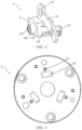
- FIG. 1 shows a schematic structural diagram of a fixing plate assembly 100 provided according to an implementation of this utility application.
- the fixing plate assembly 100 provided according to an implementation of this utility application is used for a tow hook of a vehicle, and comprises a bracket 1, a fixing plate 2, a travel switch 3 and a wiring harness 4.
- the fixing plate 2 is configured as a circular plate in an embodiment of FIG. 1 , such that the fixing plate 2 has an axial direction and a radial direction. Of course, the fixing plate 2 may also be configured in other shapes.
- a main shaft is connected to the center of the fixing plate 2, and an electric motor drives the main shaft to rotate in the fixing plate 2.
- the bracket 1 is fixed to the fixing plate 2 by means of a bolt.
- the travel switch 3 is clamped in the bracket 1, and the wiring harness 4 is connected to the travel switch 3 for supplying power and transmitting an electrical signal.
- the fixing plate assembly 100 may be provided with a plurality of travel switches 3, and correspondingly may be provided with a plurality of brackets 1 matching the travel switches 3 in number.
- a direction from the travel switch 3 to the bracket 1 in the axial direction of the fixing plate 2 is defined as a direction from top to bottom.
- FIG. 2 shows a schematic structural diagram of the bracket 1 of the fixing plate assembly 100 according to an implementation of this utility application.
- the bracket 1 comprises a limiting portion 11, a bracket mounting portion 12, an intermediate connecting portion 13 and a wiring harness fixing portion 14.
- the travel switch 3 is clamped in the limiting portion 11.
- the travel switch 3 has a cuboid or similar shape. When the travel switch 3 is clamped in the limiting portion 11, a rectangular lower surface thereof is arranged closely against the limiting portion 11.
- the limiting portion 11 is configured as a cover shaped to match the travel switch 3, that is, a square cover, and a bottom wall 111 of the cover is in contact with the lower surface of the travel switch 3 to limit the movement of the travel switch 3 in a direction perpendicular to the fixing plate 2.
- Side walls of the cover surround and clamp the travel switch 3, thereby limiting the movement of the travel switch 3 in the direction parallel to the fixing plate 2, and also increasing the rigidity and strength around the travel switch 3.
- the side walls of the limiting portion 11 are snapped into a limiting portion mounting hole 22 (shown in FIG. 4 ) formed in the fixing plate 2, so that the position of the bracket 1 on the fixing plate 2 can be further limited.
- first clamping walls 112 and one second clamping wall 113 are further provided on the respective side walls of the limiting portion 11.
- Each of the two first clamping walls 112 and the one second clamping wall 113 is arranged on one of the side walls of the limiting portion 11, and is connected to, for example, integrally formed with, the bottom wall 111 of the limiting portion 11.
- the first clamping walls and the second clamping wall are each formed by providing two grooves 114 in the side wall of the limiting portion 11 that extend in the direction from top to bottom such that an elongated wall extending from bottom to top is formed between the two grooves 114.
- the two grooves 114 can also be used for receiving the wiring harness 4 extending out from the travel switch 3.
- the elongated wall formed by such a method has a certain elasticity, so that the travel switch 3 can be snapped into and easily taken out from the limiting portion 11.
- connecting posts for example, two connecting posts
- limiting holes 115 are correspondingly formed in one of the side walls of the limiting portion 11, that is, the side wall on which none of the first clamping walls 112 and the second clamping wall 113 is formed, and are used for engaging with the connecting posts of the travel switch 3.
- no groove 114 and no clamping wall are formed on the side wall.
- the limiting portion 11 clamps the travel switch 3 in a first direction (which is a direction parallel to the fixing plate 2 and to the length direction of the lower surface of the travel switch 3 in this embodiment) by means of the two opposite first clamping walls 112; and the limiting portion 11 clamps the travel switch 3 in a second direction (which is a direction parallel to the fixing plate 2 and to the width direction of the lower surface of the travel switch 3 in this embodiment) by means of the second clamping wall 113 and the side wall provided with the limiting holes 115.
- the first direction is perpendicular to the second direction.
- the first direction, the second direction and the axial direction of the fixing plate 2 form the x, y and z directions of a three-dimensional rectangular coordinate system
- the travel switch 3 is limited in the x, y and z directions (limited by the bottom wall of the limiting portion 11 in the z direction), so that the travel switch 3 can be prevented from being forced to move in any direction, thereby avoiding signal trigger at an improper time or trigger failure.
- the travel switch 3 may be further provided with first recesses and a second recess (not shown in the figures) shaped to match the first clamping walls 112 and the second clamping wall 113 respectively, so as to implement more stable limiting and conveniently snap the travel switch 3 into the limiting portion 11.
- FIG. 3 shows a schematic structural diagram of the bracket 1 of the fixing plate assembly 100 provided according to an implementation of this utility application, as viewed from another direction.
- a trigger ball accommodating portion 116 is further formed on the bottom wall 111 of the limiting portion 11, and the trigger ball accommodating portion 116 is, for example, integrally formed with the bottom wall 111.
- a trigger ball (not shown in the figures) for triggering the travel switch 3 is accommodated and held in the trigger ball accommodating portion 116.
- the trigger ball accommodating portion 116 is arranged on the bottom wall 111 of the limiting portion 11 and is configured as a cylinder protruding downwardly from the bottom wall 111, a through hole 117 is formed in the cylinder, the through hole 117 extends all the way to the lower surface of the travel switch 3, and the trigger ball can move by a stroke in the through hole 117 in the direction perpendicular to the fixing plate 2 and abut against a contact of the travel switch 3.
- the travel switch 3 is not triggered directly by the locking block.
- the travel switch 3 is triggered in such a way that when the locking block rotates past the trigger ball on the limiting portion 11, the trigger ball is hit to move toward the travel switch 3 in the direction perpendicular to the fixing plate 2 and abut against the contact of the travel switch 3.
- the stroke of the trigger ball in the through hole 117 is determined according to the height of the trigger ball accommodating portion 116, the height of the through hole 117 and the size of the trigger ball, and the through hole 117 at the lower surface of the trigger ball accommodating portion 116 is designed to have a diameter less than the diameter of the trigger ball so as to prevent the trigger ball from falling out of the through hole 117 due to gravity.
- the stroke of the trigger ball in the through hole 117 ensures that the trigger ball can abut against the contact of the travel switch 3 when subjected to a force of the locking block to move upwardly, thereby triggering the travel switch 3.
- the trigger ball can also return to its original position by virtue of the gravity, to wait to be driven by the locking block.
- the trigger ball when the locking block does not pass by the trigger ball, the trigger ball partly protrudes from the through hole 117 to exceed the lower surface of the limiting portion 11 due to the gravity, and when the locking block passes by and hits against the trigger ball, the trigger ball moves toward the travel switch 3 until the trigger ball compresses the contact of the travel switch 3 to trigger the travel switch 3.
- the trigger ball protrudes from the through hole 117 to exceed the lower surface of the limiting portion 11 by 1 mm when not driven by the locking block, and moves upwardly by 1.5 mm when hit by the locking block.
- a steel ball for example, having a size of D4, is used as the trigger ball.
- balls having different sizes or made of different materials may also be used.
- the limiting portion 11 is connected to the bracket mounting portion 12, a bracket mounting hole 121 is formed in the bracket mounting portion 12 and configured to fix the bracket 1 to the fixing plate 2 by means of a bolt, and a mounting hole 21 corresponding to the bracket mounting hole 121 is further formed in the fixing plate 2 to ensure precise positioning between the bracket 1 and the fixing plate 2.
- the bracket mounting portion 12 is connected to the intermediate connecting portion 13, the intermediate connecting portion 13 is configured to be of an arc-shaped structure having a certain length, and a wiring harness fixing portion 14 is formed at an end of the intermediate connecting portion 13 away from the bracket mounting portion 12 and is configured to receive and fix the wiring harness.
- the arc-shaped configuration of the intermediate connecting portion 13 can match the shape of the fixing plate 2, facilitating the mounting of the bracket 1 at a plurality of assembly positions on the fixing plate 2 in a manner of matching with the shape of the fixing plate 2, so that a route of the wiring harness 4 forms a circular arc along the shape of the intermediate connecting portion 13.
- a plurality of brackets 1 may be mounted on the fixing plate 2, such that the wiring harness 4 can be received along the circular arc-shaped intermediate connecting portions 13, and the wiring harness 4 received on the plurality of brackets 1 can form a large circular arc, thereby saving a storage space for the wiring harness 4.
- the wiring harness fixing portion 14 is, for example, integrally formed with the intermediate connecting portion 13.
- the wiring harness fixing portion 14 comprises two elastic protrusions 141 which are spaced apart from each other and protrude upwardly in the axial direction of the fixing plate 2.
- the two protrusions 141 are configured such that a gap between upper portions thereof is less than the diameter of the wiring harness, and a gap between lower portions thereof is greater than the diameter of the wiring harness. Since the protrusions 141 have elasticity, the wiring harness can be squeezed through the gap between the upper portions of the protrusions 141 and finally be accommodated in the gap between the lower portions of the protrusions 141, so that the wiring harness is received. Since the gap between the upper portions of the protrusions 141 is less than the diameter of the wiring harness, the wiring harness can be prevented from easily leaving the gap between the two protrusions 141, and the wiring harness 4 can also be conveniently taken out from the gap.
- FIG. 4 shows a schematic structural diagram of the fixing plate 2 of the fixing plate assembly 100 provided according to an implementation of this utility application.
- the fixing plate 2 is provided with a limiting portion mounting hole 22.
- the side walls of the limiting portion 11 are snapped into the limiting portion mounting hole 22 on the fixing plate 2, to cause the bottom wall 111 thereof to extend to the lower side of the fixing plate 2, so that the locking block can hit against the trigger ball accommodated in the trigger ball accommodating portion 116.
- the bracket 1 can be further limited in this way, and the fixing plate 2 surrounds the limiting portion 11, thereby increasing the rigidity and strength around the limiting portion 11.
- a tow hook comprising the fixing plate assembly described above.
- the fixing plate assembly is connected to a main shaft of the tow hook.
- the tow hook of this utility application can be mounted to various vehicles, including cars, trucks, buses, battery electric vehicles, hybrid vehicles, and so on. Therefore, the subject matter of this utility application further aims to set forth various vehicles equipped with the tow hook of this utility application.
Landscapes
- Engineering & Computer Science (AREA)
- Transportation (AREA)
- Mechanical Engineering (AREA)
- Switch Cases, Indication, And Locking (AREA)
Abstract
Description
- This utility application relates to the technical field of tow hooks of vehicles, and in particular to a fixing plate assembly, a tow hook provided with the fixing plate assembly, and a vehicle provided with the tow hook.
- An electric tow hook actuating mechanism is typically driven by an electric motor to make a tow hook reach a specified position. When the tow hook is in place, it is necessary to lock the electric tow hook to prevent the electric motor from being damaged by a reaction force of the tow hook. Therefore, in the electric tow hook actuating mechanism, when the tow hook is in place, a travel switch in the actuating mechanism is generally triggered by a rotating locking block. The travel switch is triggered when the locking block is rotated in place, and transmits a trigger signal to a controller, so that the controller obtains information indicating that the tow hook is already locked and feeds the information back to the vehicle, so that a user can proceed to the next operation.
- In the electric tow hook actuating mechanism, the locking block which triggers the travel switch is in a rotating state. If the travel switch is forced to move, signal trigger at an improper time or trigger failure will be caused, which eventually may result in the operation failure of the actuating mechanism. A conventional method for fixing the travel switch is to directly fix the travel switch to a fixing plate of the electric tow hook by using a bolt. This method causes a positioning difficulty during assembly, and the travel switch is likely to loosen after undergoing vibration and impact in use.
- In an aspect of this utility application, the technical problem to be solved is how to better position and fix a travel switch on a fixing plate.
- In addition, other aspects of this utility application aim to solve or alleviate other technical problems existing in the prior art.
- This utility application provides a fixing plate assembly, a tow hook and a vehicle. Specifically, according to an aspect of this utility application, provided is:
a fixing plate assembly used for the tow hook of the vehicle. The fixing plate assembly comprises a fixing plate and a travel switch, wherein the fixing plate assembly further comprises a bracket fixed to the fixing plate, the travel switch being mounted on a limiting portion of the bracket, and the bracket limiting the movement of the travel switch by means of the limiting portion. - Optionally, according to an implementation of this utility application, the limiting portion is configured as a cover shaped to match the travel switch, a bottom wall of the limiting portion is in contact with the travel switch, and side walls of the limiting portion surround the travel switch.
- Optionally, according to an implementation of this utility application, a first clamping wall and a second clamping wall are formed on the respective side walls, the first clamping wall and the second clamping wall are each formed between two grooves formed in an individual side wall, the grooves extend in a direction perpendicular to the fixing plate, the first clamping wall clamps the position activated switch in a first direction, and the second clamping wall clamps the position activated switch in a second direction which is perpendicular to the first direction.
- Optionally, according to an implementation of this utility application, a limiting hole is formed in one of the side walls of the limiting portion, and a connecting post formed on one side of the travel switch is engaged into the limiting hole.
- Optionally, according to an implementation of this utility application, there is one second clamping wall, which is formed on the side wall of the limiting portion that is opposite to the limiting hole, and there are two first clamping walls, which are formed on the other two opposite side walls of the limiting portion.
- Optionally, according to an implementation of this utility application, a limiting portion mounting hole is formed in the fixing plate, and the side walls of the limiting portion are snapped into the limiting portion mounting hole.
- Optionally, according to an implementation of this utility application, a trigger ball accommodating portion is formed on the limiting portion, a through hole is formed in the trigger ball accommodating portion, a trigger ball for triggering the travel switch is accommodated in the through hole, and the trigger ball is pushable by the locking block of the tow hook to move in the through hole in the direction perpendicular to the fixing plate and abuts against a contact of the travel switch.
- Optionally, according to an implementation of this utility application, the bracket further comprises a wiring harness fixing portion connected to the limiting portion, and the wiring harness fixing portion fixes a wiring harness of the travel switch to the bracket.
- Optionally, according to an implementation of this utility application, the bracket further comprises a bracket mounting portion connected to the limiting portion, a bracket mounting hole is formed in the bracket mounting portion, and the bracket is mounted on the fixing plate by means of a bolt through the bracket mounting hole.
- Optionally, according to an implementation of this utility application, the bracket further comprises an arc-shaped intermediate connecting portion with one end connected to the bracket mounting portion, and the wiring harness fixing portion is arranged at the other end of the intermediate connecting portion.
- According to another aspect of this utility application, this utility application provides a tow hook, comprising the fixing plate assembly described above.
- According to a further aspect of this utility application, this utility application provides a vehicle, comprising a tow hook described above.
- This utility application has the beneficial effects as follows.
- 1. The travel switch is fixed by using a unique bracket structure which can adapt to commonly used travel switches, so that the travel switch is more stably fixed.
- 2. The bracket structure can ensure accurate positioning of the travel switch during assembly, and can be applied in different mounting positions.
- 3. The bracket structure cooperates with the fixing plate to provide a function of protecting the travel switch, thereby increasing the strength and rigidity around the travel switch, and ensuring that no electronic element of the travel switch fails in the event of fatigue impact.
- 4. The bracket structure also fixes the wiring harness to which the travel switch is connected, thereby preventing the problems such as looseness or abnormal noise of the wiring harness in use.
- 5. A steel ball is used on the bracket structure to ensure forward triggering of the travel switch, reducing the possibility of lateral stress of the contact of the travel switch, and improving the reliability of the entire fixing plate assembly.
- The above and other features of this utility application will become apparent with reference to the accompany drawings, in which:
-
FIG. 1 shows a schematic structural diagram of a fixing plate assembly provided according to an implementation of this utility application; -
FIG. 2 shows a schematic structural diagram of a bracket of the fixing plate assembly provided according to an implementation of this utility application; -
FIG. 3 shows a schematic structural diagram of the bracket of the fixing plate assembly provided according to an implementation of this utility application, as viewed in another direction; and -
FIG. 4 shows a schematic structural diagram of a fixing plate of the fixing plate assembly provided according to an implementation of this utility application. - It can be readily understood that according to the technical solution of this utility application, a person of ordinary skill in the art may propose a plurality of interchangeable structures and implementations without changing the essential spirit of this utility application. Therefore, the following specific embodiments and the accompanying drawings are merely exemplary descriptions of the technical solution of this utility application, and should not be construed as the entirety of this utility application or construed as limiting the technical solution of this utility application.
- Orientation terms, such as up, down, left, right, front, rear, front side, back side, top, and bottom, which are or may be mentioned in this description, are defined with respect to the structures shown in the accompanying drawing, and are relative concepts, and therefore may correspondingly vary depending on different positions and different usage states. Therefore, these or other orientation terms should not be construed as restrictive terms as well. Moreover, the terms such as "first" "second", "third" or similar expressions are only used for description and distinction purposes, and should not be construed as indicating or implying the relative importance of corresponding members.
- Reference is made to
FIG. 1 , which shows a schematic structural diagram of afixing plate assembly 100 provided according to an implementation of this utility application. Thefixing plate assembly 100 provided according to an implementation of this utility application is used for a tow hook of a vehicle, and comprises abracket 1, a fixing plate 2, a travel switch 3 and a wiring harness 4. The fixing plate 2 is configured as a circular plate in an embodiment ofFIG. 1 , such that the fixing plate 2 has an axial direction and a radial direction. Of course, the fixing plate 2 may also be configured in other shapes. A main shaft is connected to the center of the fixing plate 2, and an electric motor drives the main shaft to rotate in the fixing plate 2. Thebracket 1 is fixed to the fixing plate 2 by means of a bolt. The travel switch 3 is clamped in thebracket 1, and the wiring harness 4 is connected to the travel switch 3 for supplying power and transmitting an electrical signal. As shown inFIG. 1 , thefixing plate assembly 100 may be provided with a plurality of travel switches 3, and correspondingly may be provided with a plurality ofbrackets 1 matching the travel switches 3 in number. For ease of description, a direction from the travel switch 3 to thebracket 1 in the axial direction of the fixing plate 2 is defined as a direction from top to bottom. - Reference is made to
FIG. 2 , which shows a schematic structural diagram of thebracket 1 of thefixing plate assembly 100 according to an implementation of this utility application. In an implementation of this utility application, thebracket 1 comprises alimiting portion 11, abracket mounting portion 12, an intermediate connectingportion 13 and a wiringharness fixing portion 14. The travel switch 3 is clamped in the limitingportion 11. In this implementation, the travel switch 3 has a cuboid or similar shape. When the travel switch 3 is clamped in the limitingportion 11, a rectangular lower surface thereof is arranged closely against the limitingportion 11. In this implementation, the limitingportion 11 is configured as a cover shaped to match the travel switch 3, that is, a square cover, and abottom wall 111 of the cover is in contact with the lower surface of the travel switch 3 to limit the movement of the travel switch 3 in a direction perpendicular to the fixing plate 2. Side walls of the cover surround and clamp the travel switch 3, thereby limiting the movement of the travel switch 3 in the direction parallel to the fixing plate 2, and also increasing the rigidity and strength around the travel switch 3. The side walls of the limitingportion 11 are snapped into a limiting portion mounting hole 22 (shown inFIG. 4 ) formed in the fixing plate 2, so that the position of thebracket 1 on the fixing plate 2 can be further limited. - To further limit the movement of the travel switch 3, two
first clamping walls 112 and onesecond clamping wall 113 are further provided on the respective side walls of the limitingportion 11. Each of the twofirst clamping walls 112 and the onesecond clamping wall 113 is arranged on one of the side walls of the limitingportion 11, and is connected to, for example, integrally formed with, thebottom wall 111 of the limitingportion 11. The first clamping walls and the second clamping wall are each formed by providing twogrooves 114 in the side wall of the limitingportion 11 that extend in the direction from top to bottom such that an elongated wall extending from bottom to top is formed between the twogrooves 114. The twogrooves 114 can also be used for receiving the wiring harness 4 extending out from the travel switch 3. The elongated wall formed by such a method has a certain elasticity, so that the travel switch 3 can be snapped into and easily taken out from the limitingportion 11. Typically, connecting posts (not shown in the figures), for example, two connecting posts, are formed on one of the side walls of the travel switch 3. Therefore, limitingholes 115, for example, two limiting holes, are correspondingly formed in one of the side walls of the limitingportion 11, that is, the side wall on which none of thefirst clamping walls 112 and thesecond clamping wall 113 is formed, and are used for engaging with the connecting posts of the travel switch 3. In order to prevent too low strength of this side wall, nogroove 114 and no clamping wall are formed on the side wall. Thus, the limitingportion 11 clamps the travel switch 3 in a first direction (which is a direction parallel to the fixing plate 2 and to the length direction of the lower surface of the travel switch 3 in this embodiment) by means of the two oppositefirst clamping walls 112; and the limitingportion 11 clamps the travel switch 3 in a second direction (which is a direction parallel to the fixing plate 2 and to the width direction of the lower surface of the travel switch 3 in this embodiment) by means of thesecond clamping wall 113 and the side wall provided with the limitingholes 115. The first direction is perpendicular to the second direction. In this way, the first direction, the second direction and the axial direction of the fixing plate 2 form the x, y and z directions of a three-dimensional rectangular coordinate system, and the travel switch 3 is limited in the x, y and z directions (limited by the bottom wall of the limitingportion 11 in the z direction), so that the travel switch 3 can be prevented from being forced to move in any direction, thereby avoiding signal trigger at an improper time or trigger failure. Moreover, the travel switch 3 may be further provided with first recesses and a second recess (not shown in the figures) shaped to match thefirst clamping walls 112 and thesecond clamping wall 113 respectively, so as to implement more stable limiting and conveniently snap the travel switch 3 into the limitingportion 11. - Reference is made to
FIG. 3 , which shows a schematic structural diagram of thebracket 1 of the fixingplate assembly 100 provided according to an implementation of this utility application, as viewed from another direction. In an embodiment of this utility application, a triggerball accommodating portion 116 is further formed on thebottom wall 111 of the limitingportion 11, and the triggerball accommodating portion 116 is, for example, integrally formed with thebottom wall 111. A trigger ball (not shown in the figures) for triggering the travel switch 3 is accommodated and held in the triggerball accommodating portion 116. The triggerball accommodating portion 116 is arranged on thebottom wall 111 of the limitingportion 11 and is configured as a cylinder protruding downwardly from thebottom wall 111, a throughhole 117 is formed in the cylinder, the throughhole 117 extends all the way to the lower surface of the travel switch 3, and the trigger ball can move by a stroke in the throughhole 117 in the direction perpendicular to the fixing plate 2 and abut against a contact of the travel switch 3. In this embodiment, the travel switch 3 is not triggered directly by the locking block. Instead, the travel switch 3 is triggered in such a way that when the locking block rotates past the trigger ball on the limitingportion 11, the trigger ball is hit to move toward the travel switch 3 in the direction perpendicular to the fixing plate 2 and abut against the contact of the travel switch 3. By triggering the travel switch 3 in this way, it can be ensured that the contact of the travel switch 3 is triggered forwardly only by the trigger ball, thereby reducing the possibility that the contact of the travel switch 3 is subjected to a lateral force of the locking block. The stroke of the trigger ball in the throughhole 117 is determined according to the height of the triggerball accommodating portion 116, the height of the throughhole 117 and the size of the trigger ball, and the throughhole 117 at the lower surface of the triggerball accommodating portion 116 is designed to have a diameter less than the diameter of the trigger ball so as to prevent the trigger ball from falling out of the throughhole 117 due to gravity. The stroke of the trigger ball in the throughhole 117 ensures that the trigger ball can abut against the contact of the travel switch 3 when subjected to a force of the locking block to move upwardly, thereby triggering the travel switch 3. When the locking block leaves, the trigger ball can also return to its original position by virtue of the gravity, to wait to be driven by the locking block. Typically, when the locking block does not pass by the trigger ball, the trigger ball partly protrudes from the throughhole 117 to exceed the lower surface of the limitingportion 11 due to the gravity, and when the locking block passes by and hits against the trigger ball, the trigger ball moves toward the travel switch 3 until the trigger ball compresses the contact of the travel switch 3 to trigger the travel switch 3. For example, the trigger ball protrudes from the throughhole 117 to exceed the lower surface of the limitingportion 11 by 1 mm when not driven by the locking block, and moves upwardly by 1.5 mm when hit by the locking block. A steel ball, for example, having a size of D4, is used as the trigger ball. Of course, balls having different sizes or made of different materials may also be used. - The limiting
portion 11 is connected to thebracket mounting portion 12, abracket mounting hole 121 is formed in thebracket mounting portion 12 and configured to fix thebracket 1 to the fixing plate 2 by means of a bolt, and a mountinghole 21 corresponding to thebracket mounting hole 121 is further formed in the fixing plate 2 to ensure precise positioning between thebracket 1 and the fixing plate 2. Thebracket mounting portion 12 is connected to the intermediate connectingportion 13, the intermediate connectingportion 13 is configured to be of an arc-shaped structure having a certain length, and a wiringharness fixing portion 14 is formed at an end of the intermediate connectingportion 13 away from thebracket mounting portion 12 and is configured to receive and fix the wiring harness. Since theentire bracket 1 is fixed to the circular fixing plate 2, the arc-shaped configuration of the intermediate connectingportion 13 can match the shape of the fixing plate 2, facilitating the mounting of thebracket 1 at a plurality of assembly positions on the fixing plate 2 in a manner of matching with the shape of the fixing plate 2, so that a route of the wiring harness 4 forms a circular arc along the shape of the intermediate connectingportion 13. As shown inFIG. 1 , a plurality ofbrackets 1 may be mounted on the fixing plate 2, such that the wiring harness 4 can be received along the circular arc-shaped intermediate connectingportions 13, and the wiring harness 4 received on the plurality ofbrackets 1 can form a large circular arc, thereby saving a storage space for the wiring harness 4. The wiringharness fixing portion 14 is, for example, integrally formed with the intermediate connectingportion 13. The wiringharness fixing portion 14 comprises twoelastic protrusions 141 which are spaced apart from each other and protrude upwardly in the axial direction of the fixing plate 2. The twoprotrusions 141 are configured such that a gap between upper portions thereof is less than the diameter of the wiring harness, and a gap between lower portions thereof is greater than the diameter of the wiring harness. Since theprotrusions 141 have elasticity, the wiring harness can be squeezed through the gap between the upper portions of theprotrusions 141 and finally be accommodated in the gap between the lower portions of theprotrusions 141, so that the wiring harness is received. Since the gap between the upper portions of theprotrusions 141 is less than the diameter of the wiring harness, the wiring harness can be prevented from easily leaving the gap between the twoprotrusions 141, and the wiring harness 4 can also be conveniently taken out from the gap. - Reference is made to
FIG. 4 , which shows a schematic structural diagram of the fixing plate 2 of the fixingplate assembly 100 provided according to an implementation of this utility application. In another embodiment of this utility application, the fixing plate 2 is provided with a limitingportion mounting hole 22. The side walls of the limitingportion 11 are snapped into the limitingportion mounting hole 22 on the fixing plate 2, to cause thebottom wall 111 thereof to extend to the lower side of the fixing plate 2, so that the locking block can hit against the trigger ball accommodated in the triggerball accommodating portion 116. In addition, thebracket 1 can be further limited in this way, and the fixing plate 2 surrounds the limitingportion 11, thereby increasing the rigidity and strength around the limitingportion 11. - According to another aspect of this utility application, further provided is a tow hook comprising the fixing plate assembly described above. The fixing plate assembly is connected to a main shaft of the tow hook.
- It should be understood that the tow hook of this utility application can be mounted to various vehicles, including cars, trucks, buses, battery electric vehicles, hybrid vehicles, and so on. Therefore, the subject matter of this utility application further aims to set forth various vehicles equipped with the tow hook of this utility application.
- It should be understood that all of the above preferred embodiments are exemplary rather than limiting, and any modification or variation made by those skilled in the art to the specific embodiments described above without departing from the concept of this utility application shall fall within the scope of legal protection of this utility application.
Claims (12)
- A fixing plate assembly (100) for a tow hook of a vehicle, the fixing plate assembly (100) comprising a fixing plate (2) and a travel switch (3), wherein the fixing plate assembly (100) further comprises a bracket (1) fixed to the fixing plate (2), the travel switch (3) being mounted on a limiting portion (11) of the bracket (1), and the bracket (1) limiting the movement of the travel switch (3) by means of the limiting portion (11).
- The fixing plate assembly (100) according to claim 1, wherein the limiting portion (11) is configured as a cover shaped to match the travel switch (3), a bottom wall (111) of the limiting portion is in contact with the travel switch (3), and side walls of the limiting portion surround the travel switch (3).
- The fixing plate assembly (100) according to claim 2, wherein a first clamping wall (112) and a second clamping wall (113) are formed on the respective side walls, the first clamping wall (112) and the second clamping wall (113) are each formed between two grooves (114) formed in an individual side wall, the grooves (114) extend in a direction perpendicular to the fixing plate (2), the first clamping wall (112) clamps the position activated switch (3) in a first direction, and the second clamping wall (113) clamps the position activated switch (3) in a second direction which is perpendicular to the first direction.
- The fixing plate assembly (100) according to claim 3, wherein a limiting hole (115) is formed in one of the side walls of the limiting portion (11), and a connecting post formed on one side of the travel switch (3) is engaged into the limiting hole (115).
- The fixing plate assembly (100) according to claim 4, wherein there is one second clamping wall (113), which is formed on the side wall of the limiting portion (11) that is opposite to the limiting hole (115), and there are two first clamping walls (112), which are formed on the other two opposite side walls of the limiting portion (11).
- The fixing plate assembly (100) according to claim 2, wherein a limiting portion mounting hole (22) is formed in the fixing plate (2), and the side walls of the limiting portion (11) are snapped into the limiting portion mounting hole (22).
- The fixing plate assembly (100) according to claim 6, wherein a trigger ball accommodating portion (116) is formed on the limiting portion (11), a through hole (117) is formed in the trigger ball accommodating portion (116), a trigger ball for triggering the travel switch (3) is accommodated in the through hole (117), and the trigger ball is pushable by the locking block of the tow hook to move in the through hole (117) in the direction perpendicular to the fixing plate (2) and abuts against a contact of the travel switch (3).
- The fixing plate assembly (100) according to any one of claims 1 to 7, wherein the bracket (1) further comprises a wiring harness fixing portion (14) connected to the limiting portion (11), and the wiring harness fixing portion (14) fixes a wiring harness of the travel switch (3) to the bracket (1).
- The fixing plate assembly (100) according to claim 8, wherein the bracket (1) further comprises a bracket mounting portion (12) connected to the limiting portion, a bracket mounting hole (121) is formed in the bracket mounting portion (12), and the bracket (1) is mounted on the fixing plate (2) by means of a bolt through the bracket mounting hole (121).
- The fixing plate assembly (100) according to claim 9, wherein the bracket (1) further comprises an arc-shaped intermediate connecting portion (13) with one end connected to the bracket mounting portion (12), and the wiring harness fixing portion (14) is arranged at the other end of the intermediate connecting portion (13).
- A tow hook, comprising a fixing plate assembly (100) according to any one of claims 1 to 10.
- A vehicle, comprising a tow hook according to claim 11.
Applications Claiming Priority (2)
| Application Number | Priority Date | Filing Date | Title |
|---|---|---|---|
| CN202220834521.7U CN217705400U (en) | 2022-04-12 | 2022-04-12 | Fixed plate assembly, trailer hook and vehicle |
| PCT/CN2023/085914 WO2023197900A1 (en) | 2022-04-12 | 2023-04-03 | Fixing plate assembly, tow hook, and vehicle |
Publications (2)
| Publication Number | Publication Date |
|---|---|
| EP4509334A1 true EP4509334A1 (en) | 2025-02-19 |
| EP4509334A4 EP4509334A4 (en) | 2026-03-04 |
Family
ID=83789498
Family Applications (1)
| Application Number | Title | Priority Date | Filing Date |
|---|---|---|---|
| EP23787545.5A Pending EP4509334A4 (en) | 2022-04-12 | 2023-04-03 | Fixing plate assembly, tow hook, and vehicle |
Country Status (3)
| Country | Link |
|---|---|
| EP (1) | EP4509334A4 (en) |
| CN (1) | CN217705400U (en) |
| WO (1) | WO2023197900A1 (en) |
Families Citing this family (2)
| Publication number | Priority date | Publication date | Assignee | Title |
|---|---|---|---|---|
| CN217705400U (en) * | 2022-04-12 | 2022-11-01 | 蔚来汽车科技(安徽)有限公司 | Fixed plate assembly, trailer hook and vehicle |
| CN222531215U (en) * | 2024-01-24 | 2025-02-25 | 安徽威灵汽车部件有限公司 | Wire harness bracket, compressor assembly and vehicle |
Family Cites Families (7)
| Publication number | Priority date | Publication date | Assignee | Title |
|---|---|---|---|---|
| DE19711535C2 (en) * | 1997-03-20 | 2003-07-17 | Jaeger Cartronix Gmbh | Motorized trailer hitch for motor vehicles |
| DE102008034848A1 (en) * | 2008-06-06 | 2009-12-17 | Westfalia-Automotive Gmbh | Towing |
| CN206297366U (en) * | 2016-12-29 | 2017-07-04 | 长城汽车股份有限公司 | Cover plate installation structure and vehicle |
| CZ308583B6 (en) * | 2017-01-20 | 2020-12-16 | Vapos, Spol. S R.O. | Automatic tilting towing device, especially for passenger cars |
| CN113524993B (en) * | 2021-05-20 | 2023-03-21 | 浙江致优汽车科技有限公司 | Self-locking electric trailer hook device |
| CN217588723U (en) * | 2022-03-31 | 2022-10-14 | 蔚来汽车科技(安徽)有限公司 | Travel switch, trailer coupler and vehicle |
| CN217705400U (en) * | 2022-04-12 | 2022-11-01 | 蔚来汽车科技(安徽)有限公司 | Fixed plate assembly, trailer hook and vehicle |
-
2022
- 2022-04-12 CN CN202220834521.7U patent/CN217705400U/en active Active
-
2023
- 2023-04-03 WO PCT/CN2023/085914 patent/WO2023197900A1/en not_active Ceased
- 2023-04-03 EP EP23787545.5A patent/EP4509334A4/en active Pending
Also Published As
| Publication number | Publication date |
|---|---|
| CN217705400U (en) | 2022-11-01 |
| WO2023197900A1 (en) | 2023-10-19 |
| EP4509334A4 (en) | 2026-03-04 |
Similar Documents
| Publication | Publication Date | Title |
|---|---|---|
| CN112238411B (en) | Electric tool and rotary tool | |
| US6547020B2 (en) | Battery mounting assembly | |
| CN217705400U (en) | Fixed plate assembly, trailer hook and vehicle | |
| MX2012013430A (en) | PROTECTION APPLIANCE AGAINST VEHICLE COLLISION. | |
| US9358864B2 (en) | Device for fastening a battery module to a bodyshell of a motor vehicle | |
| JP7141998B2 (en) | Protective member and protective structure | |
| JP7103966B2 (en) | Switching device | |
| CN112448073B (en) | Battery pack modules and electrically driven motor vehicles | |
| US8657355B2 (en) | Protective structure for high-voltage unit | |
| CN219134035U (en) | Controller Mounting Bracket and Vehicle | |
| CN116691541B (en) | Electric vehicle | |
| JP3393569B2 (en) | Washer tank mounting structure | |
| CN117498050A (en) | Ground wire device and its hooking method and removal method | |
| CN222611097U (en) | Safety clip assembly and vehicle | |
| CN211543236U (en) | Locking mechanism assembly and electric automobile | |
| CN210526469U (en) | Protective structure of automobile chassis | |
| CN223702274U (en) | Battery swapping facilities and vehicles | |
| JP2003009354A (en) | Electrical junction box | |
| CN219548524U (en) | Parking space with anti-collision structure | |
| CN219029334U (en) | Wire harness fixing support | |
| CN222775515U (en) | Output pole base and battery having the same | |
| EP4632956A1 (en) | Terminal block, bus bar device, and battery pack | |
| CN212434793U (en) | Universal wiring end of storage battery | |
| CN213292567U (en) | Balance car wheel shaft fixing device and balance car | |
| CN214189586U (en) | Vibration isolators for retractors, retractors and vehicles |
Legal Events
| Date | Code | Title | Description |
|---|---|---|---|
| STAA | Information on the status of an ep patent application or granted ep patent |
Free format text: STATUS: THE INTERNATIONAL PUBLICATION HAS BEEN MADE |
|
| PUAI | Public reference made under article 153(3) epc to a published international application that has entered the european phase |
Free format text: ORIGINAL CODE: 0009012 |
|
| STAA | Information on the status of an ep patent application or granted ep patent |
Free format text: STATUS: REQUEST FOR EXAMINATION WAS MADE |
|
| 17P | Request for examination filed |
Effective date: 20241111 |
|
| AK | Designated contracting states |
Kind code of ref document: A1 Designated state(s): AL AT BE BG CH CY CZ DE DK EE ES FI FR GB GR HR HU IE IS IT LI LT LU LV MC ME MK MT NL NO PL PT RO RS SE SI SK SM TR |
|
| DAV | Request for validation of the european patent (deleted) | ||
| DAX | Request for extension of the european patent (deleted) | ||
| A4 | Supplementary search report drawn up and despatched |
Effective date: 20260203 |
|
| RIC1 | Information provided on ipc code assigned before grant |
Ipc: B60D 1/48 20060101AFI20260128BHEP |