EP4509241A1 - Hot-stamp-formed article - Google Patents
Hot-stamp-formed article Download PDFInfo
- Publication number
- EP4509241A1 EP4509241A1 EP23788060.4A EP23788060A EP4509241A1 EP 4509241 A1 EP4509241 A1 EP 4509241A1 EP 23788060 A EP23788060 A EP 23788060A EP 4509241 A1 EP4509241 A1 EP 4509241A1
- Authority
- EP
- European Patent Office
- Prior art keywords
- steel
- present
- hot
- less
- content
- Prior art date
- Legal status (The legal status is an assumption and is not a legal conclusion. Google has not performed a legal analysis and makes no representation as to the accuracy of the status listed.)
- Pending
Links
Images

Classifications
-
- B—PERFORMING OPERATIONS; TRANSPORTING
- B21—MECHANICAL METAL-WORKING WITHOUT ESSENTIALLY REMOVING MATERIAL; PUNCHING METAL
- B21D—WORKING OR PROCESSING OF SHEET METAL OR METAL TUBES, RODS OR PROFILES WITHOUT ESSENTIALLY REMOVING MATERIAL; PUNCHING METAL
- B21D22/00—Shaping without cutting, by stamping, spinning, or deep-drawing
- B21D22/20—Deep-drawing
-
- C—CHEMISTRY; METALLURGY
- C22—METALLURGY; FERROUS OR NON-FERROUS ALLOYS; TREATMENT OF ALLOYS OR NON-FERROUS METALS
- C22C—ALLOYS
- C22C38/00—Ferrous alloys, e.g. steel alloys
- C22C38/18—Ferrous alloys, e.g. steel alloys containing chromium
- C22C38/38—Ferrous alloys, e.g. steel alloys containing chromium with more than 1.5% by weight of manganese
-
- B—PERFORMING OPERATIONS; TRANSPORTING
- B21—MECHANICAL METAL-WORKING WITHOUT ESSENTIALLY REMOVING MATERIAL; PUNCHING METAL
- B21D—WORKING OR PROCESSING OF SHEET METAL OR METAL TUBES, RODS OR PROFILES WITHOUT ESSENTIALLY REMOVING MATERIAL; PUNCHING METAL
- B21D22/00—Shaping without cutting, by stamping, spinning, or deep-drawing
- B21D22/02—Stamping using rigid devices or tools
- B21D22/022—Stamping using rigid devices or tools by heating the blank or stamping associated with heat treatment
-
- C—CHEMISTRY; METALLURGY
- C21—METALLURGY OF IRON
- C21D—MODIFYING THE PHYSICAL STRUCTURE OF FERROUS METALS; GENERAL DEVICES FOR HEAT TREATMENT OF FERROUS OR NON-FERROUS METALS OR ALLOYS; MAKING METAL MALLEABLE, e.g. BY DECARBURISATION OR TEMPERING
- C21D1/00—General methods or devices for heat treatment, e.g. annealing, hardening, quenching or tempering
- C21D1/18—Hardening; Quenching with or without subsequent tempering
-
- C—CHEMISTRY; METALLURGY
- C21—METALLURGY OF IRON
- C21D—MODIFYING THE PHYSICAL STRUCTURE OF FERROUS METALS; GENERAL DEVICES FOR HEAT TREATMENT OF FERROUS OR NON-FERROUS METALS OR ALLOYS; MAKING METAL MALLEABLE, e.g. BY DECARBURISATION OR TEMPERING
- C21D1/00—General methods or devices for heat treatment, e.g. annealing, hardening, quenching or tempering
- C21D1/62—Quenching devices
- C21D1/673—Quenching devices for die quenching
-
- C—CHEMISTRY; METALLURGY
- C21—METALLURGY OF IRON
- C21D—MODIFYING THE PHYSICAL STRUCTURE OF FERROUS METALS; GENERAL DEVICES FOR HEAT TREATMENT OF FERROUS OR NON-FERROUS METALS OR ALLOYS; MAKING METAL MALLEABLE, e.g. BY DECARBURISATION OR TEMPERING
- C21D7/00—Modifying the physical properties of iron or steel by deformation
- C21D7/13—Modifying the physical properties of iron or steel by deformation by hot working
-
- C—CHEMISTRY; METALLURGY
- C21—METALLURGY OF IRON
- C21D—MODIFYING THE PHYSICAL STRUCTURE OF FERROUS METALS; GENERAL DEVICES FOR HEAT TREATMENT OF FERROUS OR NON-FERROUS METALS OR ALLOYS; MAKING METAL MALLEABLE, e.g. BY DECARBURISATION OR TEMPERING
- C21D8/00—Modifying the physical properties of ferrous metals or ferrous alloys by deformation combined with, or followed by, heat treatment
-
- C—CHEMISTRY; METALLURGY
- C21—METALLURGY OF IRON
- C21D—MODIFYING THE PHYSICAL STRUCTURE OF FERROUS METALS; GENERAL DEVICES FOR HEAT TREATMENT OF FERROUS OR NON-FERROUS METALS OR ALLOYS; MAKING METAL MALLEABLE, e.g. BY DECARBURISATION OR TEMPERING
- C21D8/00—Modifying the physical properties of ferrous metals or ferrous alloys by deformation combined with, or followed by, heat treatment
- C21D8/02—Modifying the physical properties of ferrous metals or ferrous alloys by deformation combined with, or followed by, heat treatment during manufacturing of plates or strips
-
- C—CHEMISTRY; METALLURGY
- C21—METALLURGY OF IRON
- C21D—MODIFYING THE PHYSICAL STRUCTURE OF FERROUS METALS; GENERAL DEVICES FOR HEAT TREATMENT OF FERROUS OR NON-FERROUS METALS OR ALLOYS; MAKING METAL MALLEABLE, e.g. BY DECARBURISATION OR TEMPERING
- C21D9/00—Heat treatment, e.g. annealing, hardening, quenching or tempering, adapted for particular articles; Furnaces therefor
- C21D9/0068—Heat treatment, e.g. annealing, hardening, quenching or tempering, adapted for particular articles; Furnaces therefor for particular articles not mentioned below
-
- C—CHEMISTRY; METALLURGY
- C21—METALLURGY OF IRON
- C21D—MODIFYING THE PHYSICAL STRUCTURE OF FERROUS METALS; GENERAL DEVICES FOR HEAT TREATMENT OF FERROUS OR NON-FERROUS METALS OR ALLOYS; MAKING METAL MALLEABLE, e.g. BY DECARBURISATION OR TEMPERING
- C21D9/00—Heat treatment, e.g. annealing, hardening, quenching or tempering, adapted for particular articles; Furnaces therefor
- C21D9/46—Heat treatment, e.g. annealing, hardening, quenching or tempering, adapted for particular articles; Furnaces therefor for sheet metals
-
- C—CHEMISTRY; METALLURGY
- C22—METALLURGY; FERROUS OR NON-FERROUS ALLOYS; TREATMENT OF ALLOYS OR NON-FERROUS METALS
- C22C—ALLOYS
- C22C38/00—Ferrous alloys, e.g. steel alloys
- C22C38/002—Ferrous alloys, e.g. steel alloys containing In, Mg, or other elements not provided for in one single group C22C38/001 - C22C38/60
-
- C—CHEMISTRY; METALLURGY
- C22—METALLURGY; FERROUS OR NON-FERROUS ALLOYS; TREATMENT OF ALLOYS OR NON-FERROUS METALS
- C22C—ALLOYS
- C22C38/00—Ferrous alloys, e.g. steel alloys
- C22C38/005—Ferrous alloys, e.g. steel alloys containing rare earths, i.e. Sc, Y, Lanthanides
-
- C—CHEMISTRY; METALLURGY
- C22—METALLURGY; FERROUS OR NON-FERROUS ALLOYS; TREATMENT OF ALLOYS OR NON-FERROUS METALS
- C22C—ALLOYS
- C22C38/00—Ferrous alloys, e.g. steel alloys
- C22C38/008—Ferrous alloys, e.g. steel alloys containing tin
-
- C—CHEMISTRY; METALLURGY
- C22—METALLURGY; FERROUS OR NON-FERROUS ALLOYS; TREATMENT OF ALLOYS OR NON-FERROUS METALS
- C22C—ALLOYS
- C22C38/00—Ferrous alloys, e.g. steel alloys
- C22C38/02—Ferrous alloys, e.g. steel alloys containing silicon
-
- C—CHEMISTRY; METALLURGY
- C22—METALLURGY; FERROUS OR NON-FERROUS ALLOYS; TREATMENT OF ALLOYS OR NON-FERROUS METALS
- C22C—ALLOYS
- C22C38/00—Ferrous alloys, e.g. steel alloys
- C22C38/04—Ferrous alloys, e.g. steel alloys containing manganese
-
- C—CHEMISTRY; METALLURGY
- C22—METALLURGY; FERROUS OR NON-FERROUS ALLOYS; TREATMENT OF ALLOYS OR NON-FERROUS METALS
- C22C—ALLOYS
- C22C38/00—Ferrous alloys, e.g. steel alloys
- C22C38/06—Ferrous alloys, e.g. steel alloys containing aluminium
-
- C—CHEMISTRY; METALLURGY
- C22—METALLURGY; FERROUS OR NON-FERROUS ALLOYS; TREATMENT OF ALLOYS OR NON-FERROUS METALS
- C22C—ALLOYS
- C22C38/00—Ferrous alloys, e.g. steel alloys
- C22C38/18—Ferrous alloys, e.g. steel alloys containing chromium
- C22C38/20—Ferrous alloys, e.g. steel alloys containing chromium with copper
-
- C—CHEMISTRY; METALLURGY
- C22—METALLURGY; FERROUS OR NON-FERROUS ALLOYS; TREATMENT OF ALLOYS OR NON-FERROUS METALS
- C22C—ALLOYS
- C22C38/00—Ferrous alloys, e.g. steel alloys
- C22C38/18—Ferrous alloys, e.g. steel alloys containing chromium
- C22C38/22—Ferrous alloys, e.g. steel alloys containing chromium with molybdenum or tungsten
-
- C—CHEMISTRY; METALLURGY
- C22—METALLURGY; FERROUS OR NON-FERROUS ALLOYS; TREATMENT OF ALLOYS OR NON-FERROUS METALS
- C22C—ALLOYS
- C22C38/00—Ferrous alloys, e.g. steel alloys
- C22C38/18—Ferrous alloys, e.g. steel alloys containing chromium
- C22C38/24—Ferrous alloys, e.g. steel alloys containing chromium with vanadium
-
- C—CHEMISTRY; METALLURGY
- C22—METALLURGY; FERROUS OR NON-FERROUS ALLOYS; TREATMENT OF ALLOYS OR NON-FERROUS METALS
- C22C—ALLOYS
- C22C38/00—Ferrous alloys, e.g. steel alloys
- C22C38/18—Ferrous alloys, e.g. steel alloys containing chromium
- C22C38/26—Ferrous alloys, e.g. steel alloys containing chromium with niobium or tantalum
-
- C—CHEMISTRY; METALLURGY
- C22—METALLURGY; FERROUS OR NON-FERROUS ALLOYS; TREATMENT OF ALLOYS OR NON-FERROUS METALS
- C22C—ALLOYS
- C22C38/00—Ferrous alloys, e.g. steel alloys
- C22C38/18—Ferrous alloys, e.g. steel alloys containing chromium
- C22C38/28—Ferrous alloys, e.g. steel alloys containing chromium with titanium or zirconium
-
- C—CHEMISTRY; METALLURGY
- C22—METALLURGY; FERROUS OR NON-FERROUS ALLOYS; TREATMENT OF ALLOYS OR NON-FERROUS METALS
- C22C—ALLOYS
- C22C38/00—Ferrous alloys, e.g. steel alloys
- C22C38/18—Ferrous alloys, e.g. steel alloys containing chromium
- C22C38/30—Ferrous alloys, e.g. steel alloys containing chromium with cobalt
-
- C—CHEMISTRY; METALLURGY
- C22—METALLURGY; FERROUS OR NON-FERROUS ALLOYS; TREATMENT OF ALLOYS OR NON-FERROUS METALS
- C22C—ALLOYS
- C22C38/00—Ferrous alloys, e.g. steel alloys
- C22C38/18—Ferrous alloys, e.g. steel alloys containing chromium
- C22C38/32—Ferrous alloys, e.g. steel alloys containing chromium with boron
-
- C—CHEMISTRY; METALLURGY
- C22—METALLURGY; FERROUS OR NON-FERROUS ALLOYS; TREATMENT OF ALLOYS OR NON-FERROUS METALS
- C22C—ALLOYS
- C22C38/00—Ferrous alloys, e.g. steel alloys
- C22C38/18—Ferrous alloys, e.g. steel alloys containing chromium
- C22C38/34—Ferrous alloys, e.g. steel alloys containing chromium with more than 1.5% by weight of silicon
-
- C—CHEMISTRY; METALLURGY
- C22—METALLURGY; FERROUS OR NON-FERROUS ALLOYS; TREATMENT OF ALLOYS OR NON-FERROUS METALS
- C22C—ALLOYS
- C22C38/00—Ferrous alloys, e.g. steel alloys
- C22C38/18—Ferrous alloys, e.g. steel alloys containing chromium
- C22C38/40—Ferrous alloys, e.g. steel alloys containing chromium with nickel
- C22C38/44—Ferrous alloys, e.g. steel alloys containing chromium with nickel with molybdenum or tungsten
-
- C—CHEMISTRY; METALLURGY
- C22—METALLURGY; FERROUS OR NON-FERROUS ALLOYS; TREATMENT OF ALLOYS OR NON-FERROUS METALS
- C22C—ALLOYS
- C22C38/00—Ferrous alloys, e.g. steel alloys
- C22C38/18—Ferrous alloys, e.g. steel alloys containing chromium
- C22C38/40—Ferrous alloys, e.g. steel alloys containing chromium with nickel
- C22C38/48—Ferrous alloys, e.g. steel alloys containing chromium with nickel with niobium or tantalum
-
- C—CHEMISTRY; METALLURGY
- C22—METALLURGY; FERROUS OR NON-FERROUS ALLOYS; TREATMENT OF ALLOYS OR NON-FERROUS METALS
- C22C—ALLOYS
- C22C38/00—Ferrous alloys, e.g. steel alloys
- C22C38/18—Ferrous alloys, e.g. steel alloys containing chromium
- C22C38/40—Ferrous alloys, e.g. steel alloys containing chromium with nickel
- C22C38/50—Ferrous alloys, e.g. steel alloys containing chromium with nickel with titanium or zirconium
-
- C—CHEMISTRY; METALLURGY
- C22—METALLURGY; FERROUS OR NON-FERROUS ALLOYS; TREATMENT OF ALLOYS OR NON-FERROUS METALS
- C22C—ALLOYS
- C22C38/00—Ferrous alloys, e.g. steel alloys
- C22C38/18—Ferrous alloys, e.g. steel alloys containing chromium
- C22C38/40—Ferrous alloys, e.g. steel alloys containing chromium with nickel
- C22C38/54—Ferrous alloys, e.g. steel alloys containing chromium with nickel with boron
-
- C—CHEMISTRY; METALLURGY
- C22—METALLURGY; FERROUS OR NON-FERROUS ALLOYS; TREATMENT OF ALLOYS OR NON-FERROUS METALS
- C22C—ALLOYS
- C22C38/00—Ferrous alloys, e.g. steel alloys
- C22C38/18—Ferrous alloys, e.g. steel alloys containing chromium
- C22C38/40—Ferrous alloys, e.g. steel alloys containing chromium with nickel
- C22C38/58—Ferrous alloys, e.g. steel alloys containing chromium with nickel with more than 1.5% by weight of manganese
-
- C—CHEMISTRY; METALLURGY
- C22—METALLURGY; FERROUS OR NON-FERROUS ALLOYS; TREATMENT OF ALLOYS OR NON-FERROUS METALS
- C22C—ALLOYS
- C22C38/00—Ferrous alloys, e.g. steel alloys
- C22C38/60—Ferrous alloys, e.g. steel alloys containing lead, selenium, tellurium, or antimony, or more than 0.04% by weight of sulfur
-
- C—CHEMISTRY; METALLURGY
- C21—METALLURGY OF IRON
- C21D—MODIFYING THE PHYSICAL STRUCTURE OF FERROUS METALS; GENERAL DEVICES FOR HEAT TREATMENT OF FERROUS OR NON-FERROUS METALS OR ALLOYS; MAKING METAL MALLEABLE, e.g. BY DECARBURISATION OR TEMPERING
- C21D1/00—General methods or devices for heat treatment, e.g. annealing, hardening, quenching or tempering
- C21D1/74—Methods of treatment in inert gas, controlled atmosphere, vacuum or pulverulent material
- C21D1/76—Adjusting the composition of the atmosphere
-
- C—CHEMISTRY; METALLURGY
- C21—METALLURGY OF IRON
- C21D—MODIFYING THE PHYSICAL STRUCTURE OF FERROUS METALS; GENERAL DEVICES FOR HEAT TREATMENT OF FERROUS OR NON-FERROUS METALS OR ALLOYS; MAKING METAL MALLEABLE, e.g. BY DECARBURISATION OR TEMPERING
- C21D2211/00—Microstructure comprising significant phases
- C21D2211/001—Austenite
-
- C—CHEMISTRY; METALLURGY
- C21—METALLURGY OF IRON
- C21D—MODIFYING THE PHYSICAL STRUCTURE OF FERROUS METALS; GENERAL DEVICES FOR HEAT TREATMENT OF FERROUS OR NON-FERROUS METALS OR ALLOYS; MAKING METAL MALLEABLE, e.g. BY DECARBURISATION OR TEMPERING
- C21D2211/00—Microstructure comprising significant phases
- C21D2211/002—Bainite
-
- C—CHEMISTRY; METALLURGY
- C21—METALLURGY OF IRON
- C21D—MODIFYING THE PHYSICAL STRUCTURE OF FERROUS METALS; GENERAL DEVICES FOR HEAT TREATMENT OF FERROUS OR NON-FERROUS METALS OR ALLOYS; MAKING METAL MALLEABLE, e.g. BY DECARBURISATION OR TEMPERING
- C21D2211/00—Microstructure comprising significant phases
- C21D2211/008—Martensite
-
- C—CHEMISTRY; METALLURGY
- C21—METALLURGY OF IRON
- C21D—MODIFYING THE PHYSICAL STRUCTURE OF FERROUS METALS; GENERAL DEVICES FOR HEAT TREATMENT OF FERROUS OR NON-FERROUS METALS OR ALLOYS; MAKING METAL MALLEABLE, e.g. BY DECARBURISATION OR TEMPERING
- C21D8/00—Modifying the physical properties of ferrous metals or ferrous alloys by deformation combined with, or followed by, heat treatment
- C21D8/02—Modifying the physical properties of ferrous metals or ferrous alloys by deformation combined with, or followed by, heat treatment during manufacturing of plates or strips
- C21D8/0221—Modifying the physical properties of ferrous metals or ferrous alloys by deformation combined with, or followed by, heat treatment during manufacturing of plates or strips characterised by the working steps
- C21D8/0226—Hot rolling
-
- C—CHEMISTRY; METALLURGY
- C21—METALLURGY OF IRON
- C21D—MODIFYING THE PHYSICAL STRUCTURE OF FERROUS METALS; GENERAL DEVICES FOR HEAT TREATMENT OF FERROUS OR NON-FERROUS METALS OR ALLOYS; MAKING METAL MALLEABLE, e.g. BY DECARBURISATION OR TEMPERING
- C21D8/00—Modifying the physical properties of ferrous metals or ferrous alloys by deformation combined with, or followed by, heat treatment
- C21D8/02—Modifying the physical properties of ferrous metals or ferrous alloys by deformation combined with, or followed by, heat treatment during manufacturing of plates or strips
- C21D8/0247—Modifying the physical properties of ferrous metals or ferrous alloys by deformation combined with, or followed by, heat treatment during manufacturing of plates or strips characterised by the heat treatment
- C21D8/0263—Modifying the physical properties of ferrous metals or ferrous alloys by deformation combined with, or followed by, heat treatment during manufacturing of plates or strips characterised by the heat treatment following hot rolling
-
- C—CHEMISTRY; METALLURGY
- C21—METALLURGY OF IRON
- C21D—MODIFYING THE PHYSICAL STRUCTURE OF FERROUS METALS; GENERAL DEVICES FOR HEAT TREATMENT OF FERROUS OR NON-FERROUS METALS OR ALLOYS; MAKING METAL MALLEABLE, e.g. BY DECARBURISATION OR TEMPERING
- C21D8/00—Modifying the physical properties of ferrous metals or ferrous alloys by deformation combined with, or followed by, heat treatment
- C21D8/02—Modifying the physical properties of ferrous metals or ferrous alloys by deformation combined with, or followed by, heat treatment during manufacturing of plates or strips
- C21D8/0247—Modifying the physical properties of ferrous metals or ferrous alloys by deformation combined with, or followed by, heat treatment during manufacturing of plates or strips characterised by the heat treatment
- C21D8/0273—Final recrystallisation annealing
Definitions
- the present invention relates to a hot-stamping formed body.
- Hot stamping is attracting attention as a technique that achieves both the formability of a steel sheet into a vehicle member and strength of a vehicle member by performing hardening of the steel sheet in a die at the same time as press working.
- Patent Document 1 discloses an electrolytic zinc-based plated steel sheet having a high yield ratio and excellent bendability, in which the critical hydrogen amount in the steel is 0.20 mass ppm or less.
- Patent Document 1 PCT International Publication No. WO2020/079925
- Non-Patent Document 1 Acta Materialia, 58 (2010), 6393-6403
- Hydrogen embrittlement cracking is a phenomenon in which a steel member, to which high stress is applied in use, suddenly fractures due to hydrogen which is irrupted into the steel from an external environment. This phenomenon is also called delayed fracture due to the mode of the occurrence of fracture. It is generally known that hydrogen embrittlement cracking is more likely to occur in the steel sheet as tensile strength of the steel sheet increases. It is considered that this is because the higher tensile strength of the steel sheet, the greater residual stress in the steel sheet after a component is formed. This susceptibility to hydrogen embrittlement cracking (delayed fracture) is called hydrogen embrittlement resistance.
- Early fracture is a phenomenon in which fracture occurs at a stress lower than tensile strength estimated from the hardness of the steel member. This susceptibility to early fracture is called early fracture resistance.
- Patent Document 1 bendability is considered, but hydrogen embrittlement resistance and early fracture resistance are not considered.
- An object of the present invention is to provide a hot-stamping formed body having high strength, and excellent hydrogen embrittlement resistance and early fracture resistance.
- the gist of the present invention is as follows.
- FIG. 1 A figure explaining the method to obtain a deboronization index.
- the present inventors found that by reducing the standard deviation of grain sizes of prior austenite grains in the interior region, hydrogen embrittlement resistance and early fracture resistance of the hot-stamping formed body can be improved.
- the present inventors found that in the surface layer region, by generating a desired amount of bainite, by creating the texture with a desired crystal orientation, and by achieving a desired deboronization index, hydrogen embrittlement resistance can be further improved.
- the present inventors found that in order to obtain a hot-stamping formed body having the above features, it is particularly effective to perform finish rolling and annealing under desired conditions during manufacturing of a steel sheet for hot stamping.
- the hot-stamping formed body according to the present embodiment will be described in detail. First, the reason the chemical composition of the hot-stamping formed body according to the present embodiment is limited will be described.
- a limited numerical range described using “to” described below includes a lower limit and an upper limit. Numerical values represented using “less than” or “more than” are not included in a numerical range. All percentages (%) related to the chemical composition mean mass%.
- the hot-stamped formed body comprises, as a chemical composition, by mass%, C: more than 0.40% and 0.70% or less, Si: 0.010% to 3.00%, Mn: 0.60% to 3.00%, P: 0.100% or less, S: 0.0100% or less, N: 0.0200% or less, O: 0.0200% or less, Al: 0.0010% to 0.5000%, Nb: 0.0010% to 0.100%, Ti: 0.010% to 0.200%, Cr: 0.01% to 0.80%, Mo: 0.0010% to 1.000%, B: 0.0005% to 0.0200%, and a remainder: Fe and impurities.
- C by mass%
- C more than 0.40% and 0.70% or less
- Mn 0.60% to 3.00%
- P 0.100% or less
- S 0.100% or less
- S 0.100% or less
- S 0.0100% or less
- N: 0.0200% or less O: 0.0200%
- C is an element that improves the strength of the hot-stamping formed body.
- the C content is set to more than 0.40%.
- the C content is preferably 0.42% or more or 0.44% or more.
- the C content is set to 0.70% or less.
- the C content is preferably 0.65% or less or 0.60% or less.
- Si is an element that improves strength of the hot-stamping formed body by solid-solution strengthening.
- the Si content is set to 0.010% or more.
- the Si content is preferably 0.05% or more, 0.10% or more or 0.15% or more.
- the Si content is set to 3.00% or less.
- the Si content is preferably 2.00% or less, 1.00% or less or 0.70% or less.
- Mn promotes the transformation from prior austenite to pearlite in a hot-rolled steel sheet having the chemical composition of the present embodiment, and contributes to control of grain size distribution of prior austenite of the hot-stamping formed body.
- the Mn content is set to 0.60% or more.
- the Mn content is preferably 0.70% or more or 1.00% or more.
- the Mn content is set to 3.00% or less.
- the Mn content is preferably 2.50% or less or 2.30% or less.
- the P is an impurity element, and by segregating in the grain boundaries, it becomes a starting point for fracture and deteriorates early fracture resistance. For this reason, the P content is set to 0.100% or less.
- the P content is preferably 0.050% or less or 0.010% or less.
- the lower limit of the P content is not particularly limited, but may be 0%. However, when the P content is reduced to less than 0.0001%, the dephosphorization cost increases significantly, which is not preferable economically. For this reason, the P content may be set to 0.0001 % or more, 0.001% or more or 0.005% or more.
- S is an impurity element, and forms inclusions in steel.
- the inclusions become starting points for fracture and deteriorate early fracture resistance. For this reason, the S content is set to 0.0100% or less.
- the S content is preferably 0.0080% or less, 0.0050% or less or 0.0030% or less.
- the lower limit of the S content is not particularly limited, but may be 0%. However, when the S content is reduced to less than 0.0001%, the desulfurization cost increases significantly, which is not preferable economically. For this reason, the S content may be set to 0.0001% or more, 0.0002% or more, 0.0003% or more or 0.0010% or more.
- N is an impurity element, and forms nitrides in steel.
- the nitrides become starting points for fracture and deteriorate early fracture resistance.
- the N content is set to 0.0200% or less.
- the N content is preferably 0.0150% or less, 0.0100% or less, 0.0060% or less or 0.0040% or less.
- the lower limit of the N content is not particularly limited, but may be 0%. However, when the N content is reduced to less than 0.0001%, the denitrification cost increases significantly, which is not preferable economically. For this reason, the N content may be set to 0.0001% or more or 0.0010% or more.
- the O content is set to 0.0200% or less.
- the O content is preferably 0.0100% or less, 0.0070% or less or 0.0040% or less.
- the O content may be 0%, in order to disperse many oxides during deoxidizing of molten steel, the O content may be set to 0.0005% or more or 0.0010% or more.
- Al is an element having an effect of deoxidizing molten steel and achieving soundness of the steel.
- the Al content is set to 0.0010% or more.
- the Al content is preferably 0.0050% or more, 0.0100% or more or 0.0300% or more.
- the Al content is set to 0.5000% or less.
- the Al content is preferably 0.4000% or less, 0.3000% or less, or 0.2000% or less or 0.1000% or less.
- Nb is an element that forms carbonitride in steel and improves strength of the hot-stamping formed body by precipitation strengthening.
- the Nb content is set to 0.0010% or more.
- the Nb content is preferably 0.005% or more, 0.009% or more or 0.015% or more.
- the Nb content is set to 0.100% or less.
- the Nb content is preferably 0.080% or less or 0.060% or less.
- Ti is an element that forms carbonitride in steel and improves strength of the hot-stamping formed body by precipitation strengthening.
- the Ti content is set to 0.010% or more.
- the Ti content is preferably 0.020% or more or 0.025% or more.
- the Ti content is set to 0.200% or less.
- the Ti content is preferably 0.150% or less, 0.100% or less, 0.080% or less, 0.060% or less or 0.050% or less.
- Cr is an element that increases strength of the hot-stamping formed body by dissolving in prior austenite grains during heating before hot stamping.
- the Cr content is set to 0.01% or more.
- the Cr content is preferably 0.10% or more, 0.15% or more or 0.20% or more.
- the Cr content is set to 0.80% or less.
- the Cr content is preferably 0.70% or less, 0.50% or less or 0.40% or less.
- Mo is an element that increases strength of the hot-stamping formed body by dissolving in prior austenite grains during heating before hot stamping.
- Mo content is set to 0.0010% or more.
- the Mo content is preferably 0.010% or more, 0.050% or more or 0.100% or more.
- the Mo content is set to 1.000% or less.
- the Mo content is preferably 0.800% or less, 0.600% or less or 0.400% or less.
- B is an element that improves the hardenability of steel.
- the B content is set to 0.0005% or more.
- the B content is preferably 0.0010% or more or 0.0015% or more.
- the B content is set to 0.0200% or less.
- the B content is preferably 0.0150% or less, 0.0100% or less, 0.0080% or less, 0.0040% or less or 0.0030% or less.
- the remainder of the chemical composition of the hot-stamping formed body may be Fe and impurities.
- Elements which are unavoidably mixed from a steel raw material or scrap and/or during the manufacture of steel and are allowed in a range where the properties of the hot-stamping formed body according to the present embodiment do not deteriorate are exemplary examples of the impurities.
- the hot-stamping formed body may comprise the following elements as optional elements.
- the content of the following optional elements obtained in a case where the following optional elements are not contained is 0%.
- Co is an element that improves strength of the hot-stamping formed body by solid-solution strengthening. In order to reliably obtain the effect, it is preferable that the Co content be set to 0.01% or more. The Co content is more preferably set to 0.05% or more.
- the Co content is set to 4.00% or less. If necessary, the upper limit of Co content may be set to 1.00%, 0.50%, 0.10%, 0.05% or 0.02%.
- Ni has an effect of increasing strength of the hot-stamping formed body by dissolving in prior austenite grains during heating before hot stamping.
- the Ni content is preferably set to 0.01% or more.
- the Ni content is preferably set to 3.00% or less. If necessary, the upper limit of Ni content may be set to 1.50%, 1.00%, 0.50%, 0.10%, 0.05% or 0.02%.
- the Cu has an effect of increasing strength of the hot-stamping formed body by dissolving in prior austenite grains during heating before hot stamping.
- the Cu content is preferably set to 0.01% or more.
- the Cu content is more preferably set to 0.05% or more.
- the Cu content is preferably set to 3.00% or less. If necessary, the upper limit of Cu content may be set to 1.50%, 1.00%, 0.50%, 0.10%, 0.05% or 0.02%.
- V 0% to 3.00%
- V has an effect of forming carbonitride in steel and improves strength of the hot-stamping formed body by precipitation strengthening.
- the V content is preferably set to 0.01% or more.
- the V content is more preferably set to 0.05% or more.
- the V content is set to 3.00% or less. If necessary, the upper limit of V content may be set to 1.50%, 1.00%, 0.50%, 0.10%, 0.05% or 0.02%.
- the W has an effect of improving strength of the hot-stamping formed body.
- the W content is preferably set to 0.01% or more.
- the W content is preferably set to 0.05% or more.
- the W content is preferably set to 3.00% or less. If necessary, the upper limit of W content may be set to 1.50%, 1.00%, 0.50%, 0.10%, 0.05% or 0.02%.
- Ca is an element that suppresses generation of carbides that become starting points for fracture, and contributes to improvement of early fracture resistance.
- the Ca content is preferably set to 0.001% or more.
- the Ca content is set to 1.000% or less. If necessary, the upper limit of Ca content may be set to 0.100%, 0.010%, 0.005%, 0.001%, 0.0005% or 0.0002%.
- Mg forms oxides and sulfides in molten steel, suppresses formation of a coarse MnS, disperses a lot of fine oxides, miniaturizes the microstructure, and contributes to improvement of early fracture resistance.
- the Mg content is preferably set to 0.001% or more.
- the Mg content is set to 1.000% or less. If necessary, the upper limit of Mg content may be set to 0.100%, 0.010%, 0.005%, 0.001%, 0.0005% or 0.0002%.
- the REM suppresses generation of oxides that become starting points of fracture and contributes to improvement of early fracture resistance.
- the REM content is preferably set to 0.001% or more.
- the REM content is set to 1.000% or less. If necessary, the upper limit of REM content may be set to 0.100%, 0.010%, 0.005%, 0.001%, 0.0005% or 0.0002%.
- REM refers to a total of 17 elements that are composed of Sc, Y and lanthanoid, and the REM content refers to the total content of these elements.
- the Sb suppresses generation of oxides that become starting points of fracture and contributes to improvement of early fracture resistance.
- the Sb content is preferably set to 0.001% or more.
- the Sb content is set to 1.000% or less. If necessary, the upper limit of Sb content may be set to 0.100%, 0.050%, 0.020%, 0.010%, 0.005% or 0.002%.
- the Sn suppresses generation of oxides that become starting points of fracture and contributes to improvement of early fracture resistance.
- the Sn content is preferably set to 0.001% or more.
- the Sn content is set to 1.000% or less. If necessary, the upper limit of Sn content may be set to 0.100%, 0.050%, 0.020%, 0.010%, 0.005% or 0.002%.
- the Zr suppresses generation of oxides that become starting points of fracture and contributes to improvement of early fracture resistance.
- the Zr content is preferably set to 0.001% or more.
- the Zr content is set to 1.000% or less. If necessary, the upper limit of Zr content may be set to 0.100%, 0.050%, 0.020%, 0.010%, 0.005% or 0.002%.
- the As content is preferably set to 0.001% or more.
- the As content is set to 0.100% or less. If necessary, the upper limit of As content may be set to 0.100%, 0.050%, 0.020%, 0.010%, 0.005% or 0.002%.
- the above-mentioned chemical composition of the hot-stamping formed body may be measured by a standard analysis method.
- the chemical composition may be measured using inductively coupled plasma-atomic emission spectrometry (ICP-AES).
- ICP-AES inductively coupled plasma-atomic emission spectrometry
- C and S may be measured using a combustion-infrared absorption method
- N may be measured using an inert gas fusion-thermal conductivity method
- O may be measured using an inert gas fusion-nondispersive infrared absorption method.
- the chemical composition is analyzed after the plating layer or the coating film is removed by mechanical grinding.
- the standard deviation of grain sizes of prior austenite grains is 5.0 ⁇ m or less; in the surface layer region, which is a region between the surface and 1/25 depth of the sheet thickness from the surface, the area ratio of bainite is more than 10%, the maximum value of pole density of the texture is 4.0 or less, and the deboronization index is 0.05 or more.
- the interior region in the present embodiment refers to a region between 4/16 depth of the sheet thickness from the surface of the hot-stamping formed body and 5/16 depth of the sheet thickness from the surface.
- the surface layer region refers to a region between the surface of the hot-stamping formed body and 1/25 depth of the sheet thickness from the surface.
- the "surface” refers to the interface of the plating layer or the coating film and the base steel sheet, and for convenience, the plating layer or the coating film is excluded from the hot-stamping formed body.
- the hot-stamping formed body has the plating layer or the coating film on the surface thereof, as described below, for convenience, a region where the Fe concentration is less than 90% by mass in GD-OES measurement, that is, the plating layer or the coating film is excluded from the hot-stamping formed body, the measuring point where the Fe concentration is 90% by mass (the interface of the base steel sheet and the plating layer) is regarded as the surface of the hot-stamping formed body.
- the plating layer or the coating film is excluded from the hot-stamping formed body, when the thickness of the plating layer or the coating film is very small compared to the sheet thickness (thickness) of the hot-stamping formed body and can be ignored (however, when only the plating layer is formed, the thickness of the plating layer is often very small and can be ignored in most cases), when measuring the sheet thickness (thickness) of the hot-stamping formed body, the sheet thickness (thickness) of the hot-stamping formed body may be regarded as the sheet thickness (thickness) including the plating layer or the coating film.
- Standard deviation of grain sizes of prior austenite grains 5.0 ⁇ m or less
- the standard deviation of grain sizes of prior austenite grains is set to 5.0 ⁇ m or less, preferably 4.0 ⁇ m or less, 3.0 ⁇ m or less or 2.5 ⁇ m or less.
- the lower limit of the standard deviation of grain sizes of prior austenite grains is not particularly limited, but may be set to 0.1 ⁇ m, 0.5 ⁇ m, 1.0 ⁇ m or 1.5 ⁇ m.
- the standard deviation of grain sizes of prior austenite grains is obtained by the following method.
- a sample is cut out from an arbitrary position away from an end surface of the hot-stamping formed body by a distance of 50 mm or more (a position that avoids an end portion in a case where the sample cannot be collected at this position) so that a sheet thickness cross section parallel to a rolling direction can be observed.
- the size of the sample depends on a measurement device, but is set to a size that can be observed by about 10 mm in the rolling direction.
- the cross section of the sample is mirror-finished using liquid in which diamond powder having a grain size in the range of 1 ⁇ m to 6 ⁇ m is dispersed in a diluted solution of alcohol or the like or pure water.
- the observation surface is finished by electrolytic polishing.
- a region which has a length of 50 ⁇ m and is present between 4/16 depth of the sheet thickness from the surface and 5/16 depth of the sheet thickness from the surface is measured at a measurement interval of 0.1 ⁇ m by an electron backscatter diffraction method, and thus, crystal orientation information is obtained.
- An EBSD analyzer composed of a Schottky emission scanning electron microscope and an EBSD detector may be used for measurement, for example, an EBSD analyzer composed of JSM-7001F manufactured by JEOL Ltd. and DVC 5-type detector manufactured by TSL Solutions may be used for measurement.
- the degree of vacuum in the EBSD analyzer may be set to 9.6 ⁇ 10 -5 Pa or less, an accelerating voltage may be set to 15 kV, and an irradiation current level may be set to 13.
- the crystal orientation of prior austenite grains is calculated from the crystal orientation relationship between general prior austenite grains and grains having a body-centered structure after transformation, and after calculating the average grain size of prior austenite grains using the crystal orientation, the standard deviation is calculated.
- the method for calculating the crystal orientation of prior austenite grains is the following method.
- the crystal orientation map of the prior austenite grains is created by the method described in Non-Patent Document 1.
- an average value of a shortest diameter and a longest diameter is calculated, and the average value is regarded as the grain size of the prior austenite grain.
- the above operation is performed on all prior austenite grains except for the prior austenite grains which are not entirely included in the photographed visual fields, such as grains in an end portion of the photographed visual field, and the grain sizes of all the prior austenite grains in the photographed visual fields are obtained.
- the standard deviation of grain sizes of austenite grains is obtained.
- the rolling direction of the hot-stamping formed body is determined by the following method.
- a sample is cut out from an arbitrary position away from an end surface of the hot-stamping formed body by a distance of 50 mm or more so that a sheet thickness cross section parallel to a rolling direction can be observed.
- observations with an optical microscope at 100, 200, 500, and 1000 magnifications are performed respectively.
- an observation result with an appropriate magnification that the size of the inclusion can be measured is selected.
- the observation area is width of 500 ⁇ m or more and full of the sheet thickness, and the areas with low brightness are determined to be inclusions. The observation may be performed at multiple fields when observing.
- the cross-sectional observation of the plane parallel to the plane rotated in 5° increments is performed in the same way as the above method.
- the average values of the lengths of the long axes of the plurality of inclusions in each cross section are calculated respectively.
- the cross section in which the obtained average value of the length of the long axes of the inclusions is maximum is specified.
- a direction parallel to the longitudinal direction of the inclusion in the cross section is determined as the rolling direction.
- the microstructure of the interior region is not particularly limited as long as the desired strength, hydrogen embrittlement resistance and early fracture resistance can be obtained, for example, in area%, the microstructure may consist of martensite and bainite of 90% to 100% (90% or more and 100% or less) in total, and ferrite and residual austenite of 0% to 10% (0% or more and 10% or less) in total.
- Martensite in the present embodiment includes untempered martensite (fresh martensite) and tempered martensite.
- the microstructure of the hot-stamping formed body is measured by the following method.
- a sample is cut out from an arbitrary position away from an end surface of the hot-stamping formed body by a distance of 50 mm or more (a position that avoids an end portion in a case where the sample cannot be collected at this position) so that a sheet thickness cross section parallel to the rolling direction can be observed.
- the size of the sample depends on a measurement device, but is set to a size that can be observed by about 10 mm in the rolling direction.
- the cross section of the sample After polishing the cross section of the sample using silicon carbide paper of #600 to #1500, the cross section is mirror-finished using liquid in which diamond powder having a grain size in the range of 1 ⁇ m to 6 ⁇ m is dispersed in a diluted solution of alcohol or the like or pure water.
- the observation surface is finished by electrolytic polishing.
- a region which has a length of 50 ⁇ m and is present between 4/16 depth of the sheet thickness from the surface and 5/16 depth of the sheet thickness from the surface is measured at a measurement interval of 0.1 ⁇ m by an electron backscatter diffraction method, and thus, crystal orientation information is obtained.
- An EBSD analyzer composed of a Schottky emission scanning electron microscope and an EBSD detector may be used for measurement, for example, an EBSD analyzer composed of JSM-7001F manufactured by JEOLLtd. and DVC 5-type detector manufactured by TSL Solutions may be used for measurement.
- the degree of vacuum in the EBSD analyzer may be set to 9.6 ⁇ 10 -5 Pa or less, an accelerating voltage may be set to 15 kV, and an irradiation current level may be set to 13.
- the area ratio of the remaining region (the region where "Grain Average Misorientation" is more than 0.5°) is calculated, and this area ratio is determined as the total area ratio of martensite and bainite.
- bainite in the surface layer region By generating bainite in the surface layer region, dislocation density of the surface layer region can be decreased. As a result, irruption of hydrogen from the external environment can be suppressed, and hydrogen embrittlement resistance of the hot-stamping formed body can be improved. Furthermore, by generating bainite in the surface layer region, since excessive softening of the surface layer can be suppressed, hydrogen embrittlement resistance can be improved while maintaining a load bearing of the member. When the area ratio of bainite in the surface layer region is 10% or less, hydrogen embrittlement resistance deteriorates. For this reason, the area ratio of bainite is set to more than 10%, preferably 20% or more, 40% or more or 60% or more.
- the upper limit of the area ratio of bainite is not particularly limited, but may be set to 100%, 90% or 80%.
- martensite 0% to 90% (0% or more and 90% or less)
- ferrite and residual austenite 0% to 65% (0% or more and 65% or less) may be included.
- the area ratio of the microstructure is calculated for the surface layer region (the region between the surface and 1/25 depth of the sheet thickness from the surface) by the following method.
- a sample is cut out from an arbitrary position away from an end surface of the hot-stamping formed body by a distance of 50 mm or more (a position that avoids an end portion in a case where a sample cannot be collected at this position) so that a sheet thickness cross section parallel to the rolling direction can be observed.
- the size of the sample depends on a measurement device, but is set to a size that can be observed by about 10 mm in the rolling direction.
- the cross section of the sample After polishing the cross section of the sample using silicon carbide paper of #600 to #1500, the cross section is mirror-finished using liquid in which diamond powder having a grain size in the range of 1 ⁇ m to 6 ⁇ m is dispersed in a diluted solution of alcohol or the like or pure water.
- the observation surface is finished by electrolytic polishing.
- a region which has a length of 50 ⁇ m and is present between the surface of the hot-stamping formed body and 1/25 depth of the sheet thickness from the surface is measured at a measurement interval of 0.1 ⁇ m by an electron backscatter diffraction method, and thus, crystal orientation information is obtained.
- An EBSD analyzer composed of a Schottky emission scanning electron microscope and an EBSD detector may be used for measurement, for example, an EBSD analyzer composed of JSM-7001F manufactured by JEOL Ltd. and DVC 5-type detector manufactured by TSL Solutions may be used for measurement.
- the degree of vacuum in the EBSD analyzer may be set to 9.6 ⁇ 10 -5 Pa or less, an accelerating voltage may be set to 15 kV, and an irradiation current level may be set to 13.
- the region where "Grain Average Misorientation" is 0.5° or lower is extracted as ferrite.
- the area ratio of ferrite is obtained.
- the remaining region is extracted as martensite, and the area ratio thereof is calculated, thereby the area ratio of martensite is obtained.
- the maximum value of pole density of the texture in the surface layer region is more than 4.0, hydrogen embrittlement resistance of the hot-stamping formed body deteriorates.
- the maximum value of pole density of the texture in the surface layer region is set to 4.0 or less, preferably 3.5 or less, 3.0 or less or 2.5 or less.
- the lower limit of the pole density of the texture in the surface layer region is not particularly limited, but may be set to 1.0 or 1.2.
- the texture in the surface layer region is obtained by the following method.
- a sample is cut out from an arbitrary position away from an end surface of the hot-stamping formed body by a distance of 50 mm or more (a position that avoids an end portion in a case where the sample cannot be collected at this position) so that a sheet thickness cross section parallel to a rolling direction can be observed.
- the size of the sample depends on a measurement device, but is set to a size that can be observed by about 10 mm in the rolling direction.
- the cross section of the sample After polishing the cross section of the sample using silicon carbide paper of #600 to #1500, the cross section of the sample is mirror-finished using liquid in which diamond powder having a grain size in the range of 1 ⁇ m to 6 ⁇ m is dispersed in a diluted solution of alcohol or the like or pure water.
- the observation surface is finished by electrolytic polishing.
- a region which has a length of 1000 ⁇ m and is present between the surface and 1/25 depth of the sheet thickness from the surface is measured at a measurement interval of 5.0 ⁇ m by an electron backscatter diffraction method, and thus, crystal orientation information is obtained.
- An EBSD analyzer composed of a Schottky emission scanning electron microscope and an EBSD detector may be used for measurement, for example, an EBSD analyzer composed of JSM-7001F manufactured by JEOL Ltd. and DVC 5-type detector manufactured by TSL Solutions may be used for measurement.
- the degree of vacuum in the EBSD analyzer may be set to 9.6 ⁇ 10 -5 Pa or less, an accelerating voltage may be set to 15 kV, and an irradiation current level may be set to 13.
- the deboronization index is an index that quantitatively represents the amount of decrease of the B concentration in the surface layer region. By decreasing the B concentration in the surface layer region, deformability of prior austenite grain is improved by reducing strength of prior austenite before transformation, and the generation of grains having random orientation is facilitated in the surface layer region.
- the deboronization index in the surface layer region is less than 0.05, grains having a desired texture cannot be obtained in the surface layer region. For this reason, the deboronization index is set to 0.05 or more, preferably 0.20 or more, 0.30 or more or 0.35 or more.
- the upper limit of the deboronization index is not particularly limited, but may be set to 1.00, 0.80 or 0.60.
- the deboronization index in the surface layer region is obtained by the following method.
- An element concentration distribution in the sheet thickness direction in the hot-stamping formed body is measured using glow discharge optical emission spectrometry (GD-OES: Manufactured by Horiba, Ltd., Marcus type high-frequency glow discharge optical emission spectrometer, GD-PROFILER-HR).
- the measurement conditions are an analysis diameter of 4 mm ⁇ , a sputtering rate of 4 ⁇ m/min, an argon pressure of 600 Pa, an RF output of 35 W, and a measurement interval of 0.02 ⁇ m or less. All elements that are comprised in the hot-stamping formed body are measured.
- the hot-stamping formed body has the plating layer on the surface
- the "surface" refers to the interface of the plating layer and the base steel sheet.
- GD-OES measurement is performed after removing a part or all of the plating layer or the coating film by mechanical polishing or chemical polishing such that measurement to 200 ⁇ m depth from the surface of the base steel sheet (the interface of the plating layer and the base steel sheet) can be performed.
- a measuring point where the Fe concentration becomes 90 mass% is regarded as the surface of the hot-stamping formed body.
- the hot-stamping formed body may be referred to as a base steel sheet.
- B concentrations from the surface of the hot-stamping formed body to at least 100 ⁇ m depth from the surface are measured.
- the measurement in the depth direction of the B concentration is finished at the position of 100 ⁇ m depth from the surface.
- the measurement of the B concentration in the depth direction is continued. Then, each time a new B concentration measurement value is obtained in the depth direction, the average value of the B concentration in the region between the deepest part and 20 ⁇ m from the deepest part to the surface side is calculated.
- the absolute value of the difference between the average value of the B concentration in the region between the deepest part and 20 ⁇ m from the deepest part to the surface side and the maximum value of the measured value of the B concentration in the region between the deepest part and 20 ⁇ m from the deepest part to the surface side is 0.0006 mass% or less
- the absolute value of the difference between the average value of the B concentration in the region between the deepest part and 20 ⁇ m from the deepest part to the surface side and the minimum value of the measured value of the B concentration in the region between the deepest part and 20 ⁇ m from the deepest part to the surface side is 0.0006 mass% or less
- the measurement of the B concentration in the depth direction is finished at the position of 150 ⁇ m depth from the surface.
- the measurement of the B concentration in the depth direction is finished when the measurement of the B concentration at the position of 200 ⁇ m depth from the surface is completed. Then, at the time when the measurement of the B concentration in the depth direction is finished, the average value of the B concentration in the region between the deepest part (the deepest position where the B concentration used for calculating the deboronization index was obtained) and the position of 20 ⁇ m from the deepest part to the surface side is used for the below calculation of the deboronization index (hereinafter, the average value of the B concentration in the region will be referred to as the average B concentration at the deepest part of 20 ⁇ m).
- the shallowest depth position that satisfies the ending condition for the B concentration measurement in the depth direction is searched for, and in a case where the depth position is found, the deboronization index may be calculated without using the measurement results of the B concentration at the position deeper than the shallowest depth position.
- the B concentration may be measured from the surface to 200 ⁇ m depth from the surface, in this case, in a case where a shallowest depth position that satisfies the ending condition for B concentration measurement in the depth direction exists in a region of 100 ⁇ m or more depth from the surface, the measurement is regarded as ending at the depth position, and the deboronization index is calculated.
- the amount of decrease in the B concentration per unit depth (the value obtained by subtracting the B concentration at each measurement point from the average B concentration at the deepest part of 20 ⁇ m) is calculated, the integrated value of the product of the unit depth and the amount of decrease in the B concentration is calculated and determined as the area of the B-depletion region (area of region A in FIG. 1 ).
- the value obtained by subtracting the B concentration at each measurement point from the average B concentration at the deepest part of 20 ⁇ m is negative, it is integrated as 0 (due to the B removal phenomenon near the surface, the B concentration at each measurement point is in most cases lower than the average B concentration at the deepest part of 20 ⁇ m, and the integrated value becomes positive).
- the product of the average B concentration at the deepest part of 20 ⁇ m and the length of 200 ⁇ m is calculated as a reference area (area of rectangular region B in Fig. 1 ).
- the value obtained by dividing a B-depletion area (area of region A) by the reference area (area of region B) is defined as the deboronization index (area of region A/area of region B).
- the reference area (area of region B) is calculated by assuming that the length by which the average B concentration at the deepest part of 20 ⁇ m is multiplied is 200 ⁇ m.
- the hot-stamping formed body may have a plating layer on the surface.
- the plating layer By having the plating layer on the surface, corrosion resistance can be improved after hot stamping.
- the plating layer include an aluminum plating layer, aluminum-galvanized layer, aluminum-silicon plating layer, hot-dip galvanized layer, electrogalvanized layer, galvannealed layer, zinc-nickel plating layer, aluminum-magnesium-zinc-based plating layer.
- the steel sheet for hot stamping has the above-described chemical composition.
- the microstructure of the steel sheet for hot stamping is not particularly limited as long as a desired strength, hydrogen embrittlement resistance and early fracture resistance are obtained after hot stamping, for example, in area%, the microstructure may consist of ferrite: 5% to 90%, bainite and martensite: 0% to 100%, pearlite: 10% to 95%, and residual austenite: 0% to 5%.
- iron carbides, alloy carbides, intermetallic compounds, and inclusions may be included.
- the steel sheet for hot stamping may have a plating layer on the surface.
- the plating layer By having the plating layer on the surface, corrosion resistance can be improved after hot stamping.
- the plating layer include an aluminum plating layer, aluminum-galvanized layer, aluminum-silicon plating layer, hot-dip galvanized layer, electrogalvanized layer, galvannealed layer, zinc-nickel plating layer, aluminum-magnesium-zinc-based plating layer.
- a manufacturing method to obtain the steel sheet for hot stamping for obtaining the hot-stamping formed body according to the present embodiment will be described.
- it is particularly effective to control the finish rolling condition and the annealing condition in the manufacturing method of the steel sheet for hot stamping.
- the rolling reduction of the final pass (final rolling reduction) to 20% or more.
- the final rolling reduction can be expressed as ⁇ (t 0 -t 1 )/t 0 ⁇ 100 (%), where t 0 is the sheet thickness before rolling of the final pass, and ti is the sheet thickness after rolling of the final pass.
- the Mn content is 0.60% or more
- the casting method of molten steel the conditions of heating before hot rolling, rough rolling, coiling, and cold rolling are not particularly limited, and may be standard conditions.
- the coiling temperature may be set to 750°C or lower. By setting the coiling temperature to 750°C or lower, it is possible to suppress ferrite from being connected and arranged in the hot-rolled steel sheet after rolling, and pearlite is uniformly dispersed. This pearlite becomes a reverse transformation site of prior austenite during heating of hot stamping. For this reason, when pearlite is uniformly dispersed, the standard deviation of the grain sizes of prior austenite grains in the hot-stamping formed body becomes small. As a result, early fracture resistance of the hot-stamping formed body can be improved.
- a softening heat treatment may be performed on the coil after coiling.
- the softening heat treatment method is not particularly limited, and standard conditions may be adopted.
- annealing After cold rolling, it is preferable to perform annealing to heat for 15 seconds or more in an oxidizing atmosphere. Generally, it is preferable to perform annealing in a reducing atmosphere in order to suppress formation of scale.
- formation of scale on the steel sheet surface is promoted by performing annealing in the oxidizing atmosphere.
- the scale formed on the steel sheet surface becomes an oxidation source, and C and B in the surface layer region are oxidized. Since oxidized C and B leave the surface layer of the steel sheet, the amounts of C and B are reduced in the surface layer region.
- the strength of the prior austenite grains decreases and they become easily deformed, and grains having random orientation are likely to be generated. Thereby, grains having a desired texture can be generated in the surface layer region.
- the heating temperature during annealing may be set to a temperature range of 730°C to 900°C, and by staying in this heating temperature range for 15 seconds or more, formation of scale can be promoted while suppressing peeling of scale.
- the time for annealing is preferably 100 seconds or more, more preferably 200 seconds or more, and even more preferably 300 seconds or more.
- annealing for more than 3600 seconds is not preferable since the prior austenite grain sizes become coarser, the grain boundary diffusion rate of B decreases, removal of B does not proceed, and the deboronization index cannot be 0.05 or more. For this reason, the annealing time is preferably 3600 seconds or less.
- the annealing step may be performed again in an oxidizing atmosphere or a non-oxidizing atmosphere unless a treatment for removing oxide scale (for example, pickling) is performed.
- the oxidizing atmosphere may be any heating atmosphere that generates oxide scale on the surface layer of the steel sheet, and may be a standard condition.
- a gas combustion atmosphere it is preferable to create an atmosphere in which the mixture ratio of air and fuel (air-fuel ratio) is controlled to 0.80 or more, and more preferably controlled to exceed 1.00. It is preferable to generate an oxide scale of 15 ⁇ m or more on the steel sheet surface by annealing in the oxidizing atmosphere.
- oxide scale on the steel sheet surface remain in subsequent processes. That is, it is preferable to perform hot stamping, which will be described later, with the oxide scale remaining. Oxide scale is removed by shot blasting after hot stamping.
- oxide scale remains at the interface between the base steel sheet and the plating layer.
- the oxide scale disappears after hot stamping due to an alloying reaction during heating before hot stamping.
- a hot-stamping formed body according to the present embodiment is obtained by hot stamping the steel sheet for hot stamping manufactured by the above-described method.
- the hot stamping conditions are not particularly limited. However, for example, it is preferable to heat the steel sheet for hot stamping to a temperature range of 800°C to 1000°C and hold in this temperature range for 60 to 600 seconds. When the heating temperature is lower than 800°C, austenitization becomes insufficient, a desired distribution of prior austenite grain sizes cannot be obtained, and early fracture resistance may deteriorate. On the other hand, when the heating temperature is higher than 1000°C, the grains of prior austenite grow excessively, a desired distribution of prior austenite grain sizes cannot be obtained, and early fracture resistance may deteriorate.
- a heating atmosphere is not particularly limited, and may be standard conditions, for example, such as the atmosphere, a gas combustion atmosphere with a controlled ratio of air and fuel, or a nitrogen atmosphere, and the dew point of these gases may be controlled.
- hot stamping After holding in the temperature range, hot stamping is performed. After hot stamping, cooling may be performed to a temperature range of 250°C or lower at an average cooling rate of 20°C/s or faster.
- heating methods before hot stamping include heating using an electric furnace and gas furnace, flame heating, electrical heating, high-frequency heating, and induction heating.
- the hot-stamping formed body according to the present embodiment is obtained.
- a tempering treatment at 130°C to 600°C may be performed after hot stamping, or a baking hardening treatment after painting may be performed.
- a portion of the hot-stamping formed body may be tempered by laser irradiation or the like to provide a partially softened region.
- the obtained steel sheets for hot stamping were heated to a temperature range of higher than 800°C in a furnace continuously supplied with nitrogen gas (hot stamp heating), held in the temperature range, subjected to hot stamping, and then cooled to 250°C or lower at an average cooling rate of 20°C/s or faster.
- hot stamp heating nitrogen gas
- the hot-stamping formed bodies shown in Tables 3A to 3H were obtained.
- a gas combustion atmosphere was used in which the mixture ratio of air and fuel (air-fuel ratio) was controlled to 0.85.
- Measurements of the microstructure including the standard deviation of the grain sizes of austenite grains), deboronization index, and pole density of the texture of the hot-stamping formed body were performed by the above-described methods.
- the mechanical properties of the hot-stamping formed body were evaluated by the following methods.
- the tensile (maximum) strength TS of the hot-stamping formed body was obtained, in accordance with JIS Z 2241:2011, by preparing a No. 5 test piece from an arbitrary position of the hot-stamping formed body and conducting a tensile test.
- the crosshead speed was set to 1 mm/min.
- the tensile strength TS was 2200 MPa or more, it was determined as having high strength and successful, and when the tensile strength TS was less than 2200 MPa, it was determined as not having high strength and not successful.
- Hydrogen embrittlement resistance of the hot-stamping formed body was evaluated by the following method.
- a test piece with a length of 68 mm and a width of 6 mm was taken from an arbitrary position of the hot-stamping formed body, and the edges of the test piece were polished using silicon carbide paper of #200 to #1500, and then mirror finishing was performed using a liquid in which diamond powder with a particle size of 1 ⁇ m to 6 ⁇ m was dispersed in a diluent such as alcohol and pure water. Furthermore, the corners of the test piece were chamfered using silicon carbide paper of #200 to #1500.
- a stress of 800 MPa or more was applied to the test piece, the test piece was immersed in a liter of hydrochloric acid adjusted to pH 4 at room temperature for 48 hours, and the presence or absence of cracks was determined.
- no crack occurred under the load stress of 800 MPa or more it was determined as successful.
- an evaluation of "Fair” was used in the tables
- no crack occurred at 900MPa an evaluation of "Good” was used in the tables
- no crack occurred at 1000MPa an evaluation of "Very Good” was used in the tables
- no crack occurred at 1100MPa or higher an evaluation of "Excellent” was used in the tables.
- a crack occurred at a load stress of 800 MPa it was determined as not successful and "Bad" was described in the tables.
- the early fracture resistance was evaluated by the value calculated by dividing the tensile strength of the hot-stamping formed body, which was obtained by the above method, by the value obtained by multiplying the Vickers hardness, which was obtained by the following method, by 3.3 (tensile strength/(Vickers hardness ⁇ 3.3)). When the value was 0.60 or more, it was determined as having excellent early fracture resistance and successful, and when the value was less than 0.60, it was determined as not successful.
- the value obtained by multiplying the Vickers hardness by 3.3 is the tensile strength estimated from the hardness, and when the measured value of the tensile strength is 0.60 times or more of the estimated tensile strength, then it can be determined as having excellent early fracture resistance.
- the Vickers hardness used for evaluation of early fracture resistance was obtained by the following method. First, from an arbitrary position 50 mm or more away from the end surface of the hot-stamping formed body, a sample was cut out so that a cross section perpendicular to the surface (sheet thickness cross section) could be observed. The size of the sample depended on the measuring device, but was set to a size that could be observed by 10 mm in the rolling direction. A cross section of the sample was polished using silicon carbide paper of #600 to #1500, and then mirror finishing was performed using a liquid in which diamond powder with a particle size of 1 ⁇ m to 6 ⁇ m was dispersed in a diluent such as alcohol and pure water.
- a diluent such as alcohol and pure water.
Landscapes
- Chemical & Material Sciences (AREA)
- Engineering & Computer Science (AREA)
- Mechanical Engineering (AREA)
- Materials Engineering (AREA)
- Metallurgy (AREA)
- Organic Chemistry (AREA)
- Physics & Mathematics (AREA)
- Thermal Sciences (AREA)
- Crystallography & Structural Chemistry (AREA)
- Heat Treatment Of Sheet Steel (AREA)
- Heat Treatment Of Articles (AREA)
Abstract
This hot-stamping formed body has a predetermined chemical composition, in an interior region, a standard deviation of grain sizes of prior austenite grains of 5.0 µm or less, in a surface layer region, an area ratio of bainite of more than 10%, a maximum value of pole density of a texture of 4.0 or less, and a deboronization index of 0.05 or more.
Description
- The present invention relates to a hot-stamping formed body.
- Priority is claimed on
Japanese Patent Application No. 2022-067020, filed April 14, 2022 - In recent years, there has been a demand for a reduction in a weight of a vehicle body for a vehicle in terms of environmental protection and resource saving, and a high-strength steel sheet has been applied to vehicle members. Vehicle members are manufactured by press forming, but not only a forming load is increased but also the formability deteriorates as the strength of a steel sheet is increased. For this reason, the formability of a high-strength steel sheet into a member having a complicated shape becomes an issue.
- In order to solve this issue, the application of a hot stamping technique in which press forming is performed after a steel sheet is heated up to a high temperature of an austenite range where the steel sheet softens is in progress. Hot stamping is attracting attention as a technique that achieves both the formability of a steel sheet into a vehicle member and strength of a vehicle member by performing hardening of the steel sheet in a die at the same time as press working.
- For example, Patent Document 1 discloses an electrolytic zinc-based plated steel sheet having a high yield ratio and excellent bendability, in which the critical hydrogen amount in the steel is 0.20 mass ppm or less.
- [Patent Document 1]
PCT International Publication No. WO2020/079925 - Non-Patent Document 1: Acta Materialia, 58 (2010), 6393-6403
- In order to make vehicle members lighter, it is effective to increase the strength of steel sheets. In order to increase the strength of the steel sheets, there is a method of increasing the Mn content in order to improve hardenability of the steel sheet. However, increasing the Mn content poses problems such as hydrogen embrittlement cracking and early fracture.
- Hydrogen embrittlement cracking is a phenomenon in which a steel member, to which high stress is applied in use, suddenly fractures due to hydrogen which is irrupted into the steel from an external environment. This phenomenon is also called delayed fracture due to the mode of the occurrence of fracture. It is generally known that hydrogen embrittlement cracking is more likely to occur in the steel sheet as tensile strength of the steel sheet increases. It is considered that this is because the higher tensile strength of the steel sheet, the greater residual stress in the steel sheet after a component is formed. This susceptibility to hydrogen embrittlement cracking (delayed fracture) is called hydrogen embrittlement resistance.
- Early fracture is a phenomenon in which fracture occurs at a stress lower than tensile strength estimated from the hardness of the steel member. This susceptibility to early fracture is called early fracture resistance.
- In Patent Document 1, bendability is considered, but hydrogen embrittlement resistance and early fracture resistance are not considered.
- The present invention has been made in view of the above-mentioned problem. An object of the present invention is to provide a hot-stamping formed body having high strength, and excellent hydrogen embrittlement resistance and early fracture resistance.
- The gist of the present invention is as follows.
- [1] A hot-stamping formed body according to an aspect of the present invention comprising, as a chemical composition, by mass%:
- C: more than 0.40% and 0.70% or less;
- Si: 0.010% to 3.00%;
- Mn: 0.60% to 3.00%;
- P: 0.100% or less;
- S: 0.0100% or less;
- N: 0.0200% or less;
- O: 0.0200% or less;
- Al: 0.0010% to 0.5000%;
- Nb: 0.0010% to 0.100%;
- Ti: 0.010% to 0.200%;
- Cr: 0.01% to 0.80%;
- Mo: 0.0010% to 1.000%;
- B: 0.0005% to 0.0200%;
- Co: 0% to 4.00%;
- Ni: 0% to 3.00%;
- Cu: 0% to 3.00%;
- V: 0% to 3.00%;
- W: 0% to 3.00%;
- Ca: 0% to 1.000%;
- Mg: 0% to 1.000%;
- REM: 0% to 1.000%;
- Sb: 0% to 1.000%;
- Sn: 0% to 1.000%;
- Zr: 0% to 1.000%;
- As: 0% to 0.100%; and
- a remainder: Fe and impurities,
- in an interior region, which is a region between 4/16 depth of a sheet thickness from a surface of the hot-stamping formed body and 5/16 depth of the sheet thickness from the surface,
- a standard deviation of grain sizes of prior austenite grains is 5.0 µm or less,
- in a surface layer region, which is a region between the surface and 1/25 depth of the sheet thickness from the surface,
- an area ratio of bainite is more than 10%,
- a maximum value of pole density of a texture is 4.0 or less, and
- a deboronization index is 0.05 or more.
- [2] The hot-stamping formed body according to [1] may comprise, as the chemical composition, by mass%, one or more selected from the group consisting of:
- Co: 0.01% to 4.00%;
- Ni: 0.01% to 3.00%;
- Cu: 0.01% to 3.00%;
- V: 0.01% to 3.00%;
- W: 0.01% to 3.00%;
- Ca: 0.001% to 1.000%;
- Mg: 0.001% to 1.000%;
- REM: 0.001% to 1.000%;
- Sb: 0.001% to 1.000%;
- Sn: 0.001% to 1.000%;
- Zr: 0.001% to 1.000%; and
- As: 0.001% to 0.100%.
- According to the above-described aspects of the present invention, it is possible to provide a hot-stamping formed body having high strength, excellent hydrogen embrittlement resistance and early fracture resistance.
- [
Fig. 1 ] A figure explaining the method to obtain a deboronization index. - The present inventors found that by reducing the standard deviation of grain sizes of prior austenite grains in the interior region, hydrogen embrittlement resistance and early fracture resistance of the hot-stamping formed body can be improved. In addition, the present inventors found that in the surface layer region, by generating a desired amount of bainite, by creating the texture with a desired crystal orientation, and by achieving a desired deboronization index, hydrogen embrittlement resistance can be further improved.
- The present inventors found that in order to obtain a hot-stamping formed body having the above features, it is particularly effective to perform finish rolling and annealing under desired conditions during manufacturing of a steel sheet for hot stamping.
- Hereinafter, the hot-stamping formed body according to the present embodiment will be described in detail. First, the reason the chemical composition of the hot-stamping formed body according to the present embodiment is limited will be described.
- A limited numerical range described using "to" described below includes a lower limit and an upper limit. Numerical values represented using "less than" or "more than" are not included in a numerical range. All percentages (%) related to the chemical composition mean mass%.
- The hot-stamped formed body according to the present embodiment comprises, as a chemical composition, by mass%, C: more than 0.40% and 0.70% or less, Si: 0.010% to 3.00%, Mn: 0.60% to 3.00%, P: 0.100% or less, S: 0.0100% or less, N: 0.0200% or less, O: 0.0200% or less, Al: 0.0010% to 0.5000%, Nb: 0.0010% to 0.100%, Ti: 0.010% to 0.200%, Cr: 0.01% to 0.80%, Mo: 0.0010% to 1.000%, B: 0.0005% to 0.0200%, and a remainder: Fe and impurities. Each element will be described below.
- C is an element that improves the strength of the hot-stamping formed body. When the C content is 0.40% or less, a desired strength of the hot-stamping formed body cannot be obtained. For this reason, the C content is set to more than 0.40%. The C content is preferably 0.42% or more or 0.44% or more.
- Meanwhile, when the C content is more than 0.70%, toughness of martensite deteriorates and excellent hydrogen embrittlement resistance cannot be obtained. For this reason, the C content is set to 0.70% or less. The C content is preferably 0.65% or less or 0.60% or less.
- Si is an element that improves strength of the hot-stamping formed body by solid-solution strengthening. When the Si content is less than 0.010%, a desired strength cannot be obtained. For this reason, the Si content is set to 0.010% or more. The Si content is preferably 0.05% or more, 0.10% or more or 0.15% or more.
- Meanwhile, when the Si content is more than 3.00%, the amount of ferrite increases and a desired microstructure cannot be obtained. For this reason, the Si content is set to 3.00% or less. The Si content is preferably 2.00% or less, 1.00% or less or 0.70% or less.
- Mn promotes the transformation from prior austenite to pearlite in a hot-rolled steel sheet having the chemical composition of the present embodiment, and contributes to control of grain size distribution of prior austenite of the hot-stamping formed body. In order to set the standard deviation of grain sizes of prior austenite grains, the Mn content is set to 0.60% or more. The Mn content is preferably 0.70% or more or 1.00% or more.
- Meanwhile, when the Mn content is more than 3.00%, transformation from prior austenite to pearlite in a hot-rolled steel sheet having the chemical composition of the present embodiment is excessively promoted, and the standard deviation of grain sizes of prior austenite grains in the hot-stamping formed body cannot be set to a desired range. For this reason, the Mn content is set to 3.00% or less. The Mn content is preferably 2.50% or less or 2.30% or less.
- P is an impurity element, and by segregating in the grain boundaries, it becomes a starting point for fracture and deteriorates early fracture resistance. For this reason, the P content is set to 0.100% or less. The P content is preferably 0.050% or less or 0.010% or less.
- The lower limit of the P content is not particularly limited, but may be 0%. However, when the P content is reduced to less than 0.0001%, the dephosphorization cost increases significantly, which is not preferable economically. For this reason, the P content may be set to 0.0001 % or more, 0.001% or more or 0.005% or more.
- S is an impurity element, and forms inclusions in steel. The inclusions become starting points for fracture and deteriorate early fracture resistance. For this reason, the S content is set to 0.0100% or less. The S content is preferably 0.0080% or less, 0.0050% or less or 0.0030% or less.
- The lower limit of the S content is not particularly limited, but may be 0%. However, when the S content is reduced to less than 0.0001%, the desulfurization cost increases significantly, which is not preferable economically. For this reason, the S content may be set to 0.0001% or more, 0.0002% or more, 0.0003% or more or 0.0010% or more.
- N is an impurity element, and forms nitrides in steel. The nitrides become starting points for fracture and deteriorate early fracture resistance. For this reason, the N content is set to 0.0200% or less. The N content is preferably 0.0150% or less, 0.0100% or less, 0.0060% or less or 0.0040% or less.
- The lower limit of the N content is not particularly limited, but may be 0%. However, when the N content is reduced to less than 0.0001%, the denitrification cost increases significantly, which is not preferable economically. For this reason, the N content may be set to 0.0001% or more or 0.0010% or more.
- O forms a coarse oxide that becomes a starting point for fracture in steel when a large amount of O is comprised, and deteriorates early fracture resistance of the hot-stamping formed body. For this reason, the O content is set to 0.0200% or less. The O content is preferably 0.0100% or less, 0.0070% or less or 0.0040% or less.
- The O content may be 0%, in order to disperse many oxides during deoxidizing of molten steel, the O content may be set to 0.0005% or more or 0.0010% or more.
- Al is an element having an effect of deoxidizing molten steel and achieving soundness of the steel. When the Al content is less than 0.0010%, deoxidation is not sufficiently performed, and coarse oxides are generated and early fracture resistance deteriorates. For these reasons, the Al content is set to 0.0010% or more. The Al content is preferably 0.0050% or more, 0.0100% or more or 0.0300% or more.
- Meanwhile, when the Al content is more than 0.5000%, coarse oxides are generated in steel, and early fracture resistance of the hot-stamping formed body deteriorates. For this reason, the Al content is set to 0.5000% or less. The Al content is preferably 0.4000% or less, 0.3000% or less, or 0.2000% or less or 0.1000% or less.
- Nb is an element that forms carbonitride in steel and improves strength of the hot-stamping formed body by precipitation strengthening. When the Nb content is less than 0.0010%, a desired strength cannot be obtained. For this reason, the Nb content is set to 0.0010% or more. The Nb content is preferably 0.005% or more, 0.009% or more or 0.015% or more.
- Meanwhile, when the Nb content is more than 0.100%, many carbonitrides are generated in steel, and early fracture resistance of the hot-stamping formed body deteriorates. For this reason, the Nb content is set to 0.100% or less. The Nb content is preferably 0.080% or less or 0.060% or less.
- Ti is an element that forms carbonitride in steel and improves strength of the hot-stamping formed body by precipitation strengthening. When the Ti content is less than 0.010%, a desired strength cannot be obtained. For this reason, the Ti content is set to 0.010% or more. The Ti content is preferably 0.020% or more or 0.025% or more.
- Meanwhile, when the Ti content is more than 0.200%, many carbonitrides are generated in steel, and early fracture resistance of the hot-stamping formed body deteriorates. For this reason, the Ti content is set to 0.200% or less. The Ti content is preferably 0.150% or less, 0.100% or less, 0.080% or less, 0.060% or less or 0.050% or less.
- Cr is an element that increases strength of the hot-stamping formed body by dissolving in prior austenite grains during heating before hot stamping. When the Cr content is less than 0.01%, a desired strength cannot be obtained. For this reason, the Cr content is set to 0.01% or more. The Cr content is preferably 0.10% or more, 0.15% or more or 0.20% or more.
- Meanwhile, when the Cr content is more than 0.80%, coarse intermetallic compounds are formed in the hot-stamping formed body and early fracture resistance deteriorates. For this reason, the Cr content is set to 0.80% or less. The Cr content is preferably 0.70% or less, 0.50% or less or 0.40% or less.
- Mo is an element that increases strength of the hot-stamping formed body by dissolving in prior austenite grains during heating before hot stamping. When the Mo content is less than 0.0010%, a desired strength cannot be obtained. For this reason, the Mo content is set to 0.0010% or more. The Mo content is preferably 0.010% or more, 0.050% or more or 0.100% or more.
- Meanwhile, when the Mo content is more than 1.000%, coarse intermetallic compounds are formed in the hot-stamping formed body and early fracture resistance deteriorates. For this reason, the Mo content is set to 1.000% or less. The Mo content is preferably 0.800% or less, 0.600% or less or 0.400% or less.
- B is an element that improves the hardenability of steel. When the B content is less than 0.0005%, a desired strength cannot be obtained. For this reason, the B content is set to 0.0005% or more. The B content is preferably 0.0010% or more or 0.0015% or more.
- Meanwhile, when the B content is more than 0.0200%, coarse intermetallic compounds are formed in the hot-stamping formed body and early fracture resistance deteriorates. For this reason, the B content is set to 0.0200% or less. The B content is preferably 0.0150% or less, 0.0100% or less, 0.0080% or less, 0.0040% or less or 0.0030% or less.
- The remainder of the chemical composition of the hot-stamping formed body may be Fe and impurities. Elements which are unavoidably mixed from a steel raw material or scrap and/or during the manufacture of steel and are allowed in a range where the properties of the hot-stamping formed body according to the present embodiment do not deteriorate are exemplary examples of the impurities.
- The hot-stamping formed body may comprise the following elements as optional elements. The content of the following optional elements obtained in a case where the following optional elements are not contained is 0%.
- Co is an element that improves strength of the hot-stamping formed body by solid-solution strengthening. In order to reliably obtain the effect, it is preferable that the Co content be set to 0.01% or more. The Co content is more preferably set to 0.05% or more.
- Meanwhile, since the above effect will be saturated even if a large amount is comprised, the Co content is set to 4.00% or less. If necessary, the upper limit of Co content may be set to 1.00%, 0.50%, 0.10%, 0.05% or 0.02%.
- Ni has an effect of increasing strength of the hot-stamping formed body by dissolving in prior austenite grains during heating before hot stamping. In order to reliably obtain the effect, the Ni content is preferably set to 0.01% or more.
- Meanwhile, since the above effect will be saturated even if a large amount is comprised, the Ni content is preferably set to 3.00% or less. If necessary, the upper limit of Ni content may be set to 1.50%, 1.00%, 0.50%, 0.10%, 0.05% or 0.02%.
- Cu has an effect of increasing strength of the hot-stamping formed body by dissolving in prior austenite grains during heating before hot stamping. In order to reliably obtain the effect, the Cu content is preferably set to 0.01% or more. The Cu content is more preferably set to 0.05% or more.
- Meanwhile, since the above effect will be saturated even if a large amount is comprised, the Cu content is preferably set to 3.00% or less. If necessary, the upper limit of Cu content may be set to 1.50%, 1.00%, 0.50%, 0.10%, 0.05% or 0.02%.
- V has an effect of forming carbonitride in steel and improves strength of the hot-stamping formed body by precipitation strengthening. In order to reliably obtain the effect, the V content is preferably set to 0.01% or more. The V content is more preferably set to 0.05% or more.
- Meanwhile, when the V content is more than 3.00%, many carbonitrides are generated in steel, and early fracture resistance of the hot-stamping formed body deteriorates. For this reason, the V content is set to 3.00% or less. If necessary, the upper limit of V content may be set to 1.50%, 1.00%, 0.50%, 0.10%, 0.05% or 0.02%.
- W has an effect of improving strength of the hot-stamping formed body. In order to reliably obtain the effects, the W content is preferably set to 0.01% or more. The W content is preferably set to 0.05% or more.
- Meanwhile, since the above effect will be saturated even if a large amount is comprised, the W content is preferably set to 3.00% or less. If necessary, the upper limit of W content may be set to 1.50%, 1.00%, 0.50%, 0.10%, 0.05% or 0.02%.
- Ca is an element that suppresses generation of carbides that become starting points for fracture, and contributes to improvement of early fracture resistance. In order to reliably obtain the effect, the Ca content is preferably set to 0.001% or more.
- Meanwhile, since the above effect will be saturated even if a large amount is comprised, the Ca content is set to 1.000% or less. If necessary, the upper limit of Ca content may be set to 0.100%, 0.010%, 0.005%, 0.001%, 0.0005% or 0.0002%.
- Mg forms oxides and sulfides in molten steel, suppresses formation of a coarse MnS, disperses a lot of fine oxides, miniaturizes the microstructure, and contributes to improvement of early fracture resistance. In order to reliably obtain these effects, the Mg content is preferably set to 0.001% or more.
- Meanwhile, since the above effect will be saturated even if a large amount is comprised, the Mg content is set to 1.000% or less. If necessary, the upper limit of Mg content may be set to 0.100%, 0.010%, 0.005%, 0.001%, 0.0005% or 0.0002%.
- REM suppresses generation of oxides that become starting points of fracture and contributes to improvement of early fracture resistance. In order to reliably obtain the effect, the REM content is preferably set to 0.001% or more.
- Meanwhile, since the above effect will be saturated even if a large amount is comprised, the REM content is set to 1.000% or less. If necessary, the upper limit of REM content may be set to 0.100%, 0.010%, 0.005%, 0.001%, 0.0005% or 0.0002%.
- In the present embodiment, REM refers to a total of 17 elements that are composed of Sc, Y and lanthanoid, and the REM content refers to the total content of these elements.
- Sb suppresses generation of oxides that become starting points of fracture and contributes to improvement of early fracture resistance. In order to reliably obtain the effect, the Sb content is preferably set to 0.001% or more.
- Meanwhile, since the above effect will be saturated even if a large amount is comprised, the Sb content is set to 1.000% or less. If necessary, the upper limit of Sb content may be set to 0.100%, 0.050%, 0.020%, 0.010%, 0.005% or 0.002%.
- Sn suppresses generation of oxides that become starting points of fracture and contributes to improvement of early fracture resistance. In order to reliably obtain the effect, the Sn content is preferably set to 0.001% or more.
- Meanwhile, since the above effect will be saturated even if a large amount is comprised, the Sn content is set to 1.000% or less. If necessary, the upper limit of Sn content may be set to 0.100%, 0.050%, 0.020%, 0.010%, 0.005% or 0.002%.
- Zr suppresses generation of oxides that become starting points of fracture and contributes to improvement of early fracture resistance. In order to reliably obtain the effect, the Zr content is preferably set to 0.001% or more.
- Meanwhile, since the above effect will be saturated even if a large amount is comprised, the Zr content is set to 1.000% or less. If necessary, the upper limit of Zr content may be set to 0.100%, 0.050%, 0.020%, 0.010%, 0.005% or 0.002%.
- As refines the prior austenite grains by lowering an austenite single-phase transformation temperature, and contributes to improvement of early fracture resistance. In order to reliably obtain the effect, the As content is preferably set to 0.001% or more.
- Meanwhile, since the above effect will be saturated even if a large amount is comprised, the As content is set to 0.100% or less. If necessary, the upper limit of As content may be set to 0.100%, 0.050%, 0.020%, 0.010%, 0.005% or 0.002%.
- The above-mentioned chemical composition of the hot-stamping formed body may be measured by a standard analysis method. For example, the chemical composition may be measured using inductively coupled plasma-atomic emission spectrometry (ICP-AES). C and S may be measured using a combustion-infrared absorption method, N may be measured using an inert gas fusion-thermal conductivity method, and O may be measured using an inert gas fusion-nondispersive infrared absorption method.
- When a plating layer or a coating film is provided on the surface of the hot-stamping formed body, the chemical composition is analyzed after the plating layer or the coating film is removed by mechanical grinding.
- Next, the microstructure of the hot-stamping formed body according to the present embodiment will be described.
- In the hot-stamping formed body according to the present embodiment, in the interior region, which is a region between 4/16 depth of the sheet thickness (thickness of the hot-stamping formed body) from the surface of the hot-stamping formed body and 5/16 depth of the sheet thickness from the surface, the standard deviation of grain sizes of prior austenite grains is 5.0 µm or less; in the surface layer region, which is a region between the surface and 1/25 depth of the sheet thickness from the surface, the area ratio of bainite is more than 10%, the maximum value of pole density of the texture is 4.0 or less, and the deboronization index is 0.05 or more.
- The interior region in the present embodiment refers to a region between 4/16 depth of the sheet thickness from the surface of the hot-stamping formed body and 5/16 depth of the sheet thickness from the surface.
- In addition, the surface layer region refers to a region between the surface of the hot-stamping formed body and 1/25 depth of the sheet thickness from the surface.
- When the hot-stamping formed body has the plating layer or the coating film on the surface thereof, the "surface" refers to the interface of the plating layer or the coating film and the base steel sheet, and for convenience, the plating layer or the coating film is excluded from the hot-stamping formed body. Specifically, when the hot-stamping formed body has the plating layer or the coating film on the surface thereof, as described below, for convenience, a region where the Fe concentration is less than 90% by mass in GD-OES measurement, that is, the plating layer or the coating film is excluded from the hot-stamping formed body, the measuring point where the Fe concentration is 90% by mass (the interface of the base steel sheet and the plating layer) is regarded as the surface of the hot-stamping formed body. As described above, the plating layer or the coating film is excluded from the hot-stamping formed body, when the thickness of the plating layer or the coating film is very small compared to the sheet thickness (thickness) of the hot-stamping formed body and can be ignored (however, when only the plating layer is formed, the thickness of the plating layer is often very small and can be ignored in most cases), when measuring the sheet thickness (thickness) of the hot-stamping formed body, the sheet thickness (thickness) of the hot-stamping formed body may be regarded as the sheet thickness (thickness) including the plating layer or the coating film.
- By reducing the dispersion of grain sizes of prior austenite grains in the interior region, that is, by reducing the standard deviation, an increase of local residual stress can be suppressed. As a result, hydrogen embrittlement resistance and early fracture resistance of the hot-stamping formed body can be improved. When the standard deviation of grain sizes of prior austenite grains is more than 5.0 µm, hydrogen embrittlement resistance and early fracture resistance deteriorate. For this reason, the standard deviation of grain sizes of prior austenite grains is set to 5.0 µm or less, preferably 4.0 µm or less, 3.0 µm or less or 2.5 µm or less.
- The lower limit of the standard deviation of grain sizes of prior austenite grains is not particularly limited, but may be set to 0.1 µm, 0.5 µm, 1.0 µm or 1.5 µm.
- The standard deviation of grain sizes of prior austenite grains is obtained by the following method.
- A sample is cut out from an arbitrary position away from an end surface of the hot-stamping formed body by a distance of 50 mm or more (a position that avoids an end portion in a case where the sample cannot be collected at this position) so that a sheet thickness cross section parallel to a rolling direction can be observed. The size of the sample depends on a measurement device, but is set to a size that can be observed by about 10 mm in the rolling direction.
- After polishing the cross section of the sample using silicon carbide paper of #600 to #1500, the cross section of the sample is mirror-finished using liquid in which diamond powder having a grain size in the range of 1 µm to 6 µm is dispersed in a diluted solution of alcohol or the like or pure water. Next, the observation surface is finished by electrolytic polishing. At an arbitrary position on the cross section of the sample in a longitudinal direction, a region which has a length of 50 µm and is present between 4/16 depth of the sheet thickness from the surface and 5/16 depth of the sheet thickness from the surface is measured at a measurement interval of 0.1 µm by an electron backscatter diffraction method, and thus, crystal orientation information is obtained. An EBSD analyzer composed of a Schottky emission scanning electron microscope and an EBSD detector may be used for measurement, for example, an EBSD analyzer composed of JSM-7001F manufactured by JEOL Ltd. and DVC 5-type detector manufactured by TSL Solutions may be used for measurement. In this case, the degree of vacuum in the EBSD analyzer may be set to 9.6 × 10⁻⁵ Pa or less, an accelerating voltage may be set to 15 kV, and an irradiation current level may be set to 13.
- By using the obtained crystal orientation information, the crystal orientation of prior austenite grains is calculated from the crystal orientation relationship between general prior austenite grains and grains having a body-centered structure after transformation, and after calculating the average grain size of prior austenite grains using the crystal orientation, the standard deviation is calculated.
- The method for calculating the crystal orientation of prior austenite grains is the following method. First, the crystal orientation map of the prior austenite grains is created by the method described in Non-Patent Document 1. For one of prior austenite grain included in the observed visual field, an average value of a shortest diameter and a longest diameter is calculated, and the average value is regarded as the grain size of the prior austenite grain. The above operation is performed on all prior austenite grains except for the prior austenite grains which are not entirely included in the photographed visual fields, such as grains in an end portion of the photographed visual field, and the grain sizes of all the prior austenite grains in the photographed visual fields are obtained. By calculating the standard deviation from the obtained grain sizes of all austenite grains, the standard deviation of grain sizes of austenite grains is obtained.
- In addition, in the present embodiment, the rolling direction of the hot-stamping formed body is determined by the following method.
- First, a sample is cut out from an arbitrary position away from an end surface of the hot-stamping formed body by a distance of 50 mm or more so that a sheet thickness cross section parallel to a rolling direction can be observed. After finishing the cross section of the collected sample by mirror polishing, observations with an optical microscope at 100, 200, 500, and 1000 magnifications are performed respectively. Depending on the size of the inclusion, an observation result with an appropriate magnification that the size of the inclusion can be measured is selected. The observation area is width of 500 µm or more and full of the sheet thickness, and the areas with low brightness are determined to be inclusions. The observation may be performed at multiple fields when observing. Next, using the sheet thickness cross section initially observed by the above method as a reference, in the range of 0° to 180° with the sheet thickness direction as the axis, the cross-sectional observation of the plane parallel to the plane rotated in 5° increments is performed in the same way as the above method. The average values of the lengths of the long axes of the plurality of inclusions in each cross section are calculated respectively. The cross section in which the obtained average value of the length of the long axes of the inclusions is maximum is specified. A direction parallel to the longitudinal direction of the inclusion in the cross section is determined as the rolling direction.
- The microstructure of the interior region is not particularly limited as long as the desired strength, hydrogen embrittlement resistance and early fracture resistance can be obtained, for example, in area%, the microstructure may consist of martensite and bainite of 90% to 100% (90% or more and 100% or less) in total, and ferrite and residual austenite of 0% to 10% (0% or more and 10% or less) in total. Martensite in the present embodiment includes untempered martensite (fresh martensite) and tempered martensite.
- The microstructure of the hot-stamping formed body is measured by the following method.
- A sample is cut out from an arbitrary position away from an end surface of the hot-stamping formed body by a distance of 50 mm or more (a position that avoids an end portion in a case where the sample cannot be collected at this position) so that a sheet thickness cross section parallel to the rolling direction can be observed. The size of the sample depends on a measurement device, but is set to a size that can be observed by about 10 mm in the rolling direction.
- After polishing the cross section of the sample using silicon carbide paper of #600 to #1500, the cross section is mirror-finished using liquid in which diamond powder having a grain size in the range of 1 µm to 6 µm is dispersed in a diluted solution of alcohol or the like or pure water. Next, the observation surface is finished by electrolytic polishing. At an arbitrary position on the cross section of the sample in a longitudinal direction, a region which has a length of 50 µm and is present between 4/16 depth of the sheet thickness from the surface and 5/16 depth of the sheet thickness from the surface is measured at a measurement interval of 0.1 µm by an electron backscatter diffraction method, and thus, crystal orientation information is obtained. An EBSD analyzer composed of a Schottky emission scanning electron microscope and an EBSD detector may be used for measurement, for example, an EBSD analyzer composed of JSM-7001F manufactured by JEOLLtd. and DVC 5-type detector manufactured by TSL Solutions may be used for measurement. In this case, the degree of vacuum in the EBSD analyzer may be set to 9.6 × 10⁻⁵ Pa or less, an accelerating voltage may be set to 15 kV, and an irradiation current level may be set to 13.
- In the obtained crystal structure information, using "Phase Map" function installed in the software "OIM Analysis (registered trademark)" attached to the EBSD analyzer, a region where a crystal structure is fcc is determined as residual austenite. The area ratio of the residual austenite is calculated, thereby the area ratio of the residual austenite is obtained. Next, regions where the crystal structure is bcc is determined as bainite, martensite, and ferrite. In these regions, under the condition that boundary with 5° is regarded as the grain boundary, using "Grain Average Misorientation" function installed in the software "OIM Analysis (registered trademark)" attached to the EBSD analyzer, regions where a grain average misorientation is 0.5° or lower are extracted as ferrite. By calculating the area ratio of the extracted ferrite, the area ratio of ferrite is obtained.
- Subsequently, the area ratio of the remaining region (the region where "Grain Average Misorientation" is more than 0.5°) is calculated, and this area ratio is determined as the total area ratio of martensite and bainite.
- By generating bainite in the surface layer region, dislocation density of the surface layer region can be decreased. As a result, irruption of hydrogen from the external environment can be suppressed, and hydrogen embrittlement resistance of the hot-stamping formed body can be improved. Furthermore, by generating bainite in the surface layer region, since excessive softening of the surface layer can be suppressed, hydrogen embrittlement resistance can be improved while maintaining a load bearing of the member. When the area ratio of bainite in the surface layer region is 10% or less, hydrogen embrittlement resistance deteriorates. For this reason, the area ratio of bainite is set to more than 10%, preferably 20% or more, 40% or more or 60% or more.
- The upper limit of the area ratio of bainite is not particularly limited, but may be set to 100%, 90% or 80%.
- In the microstructure of the surface layer region, except for bainite, martensite of 0% to 90% (0% or more and 90% or less), ferrite and residual austenite of 0% to 65% (0% or more and 65% or less) may be included.
- The area ratio of the microstructure is calculated for the surface layer region (the region between the surface and 1/25 depth of the sheet thickness from the surface) by the following method.
- A sample is cut out from an arbitrary position away from an end surface of the hot-stamping formed body by a distance of 50 mm or more (a position that avoids an end portion in a case where a sample cannot be collected at this position) so that a sheet thickness cross section parallel to the rolling direction can be observed. The size of the sample depends on a measurement device, but is set to a size that can be observed by about 10 mm in the rolling direction.
- After polishing the cross section of the sample using silicon carbide paper of #600 to #1500, the cross section is mirror-finished using liquid in which diamond powder having a grain size in the range of 1 µm to 6 µm is dispersed in a diluted solution of alcohol or the like or pure water. Next, the observation surface is finished by electrolytic polishing. At an arbitrary position on the cross section of the sample in a longitudinal direction, a region which has a length of 50 µm and is present between the surface of the hot-stamping formed body and 1/25 depth of the sheet thickness from the surface is measured at a measurement interval of 0.1 µm by an electron backscatter diffraction method, and thus, crystal orientation information is obtained. An EBSD analyzer composed of a Schottky emission scanning electron microscope and an EBSD detector may be used for measurement, for example, an EBSD analyzer composed of JSM-7001F manufactured by JEOL Ltd. and DVC 5-type detector manufactured by TSL Solutions may be used for measurement. In this case, the degree of vacuum in the EBSD analyzer may be set to 9.6 × 10⁻⁵ Pa or less, an accelerating voltage may be set to 15 kV, and an irradiation current level may be set to 13.
- In the obtained crystal structure information, using the "Phase Map" function installed in the software "OIM Analysis (registered trademark)" attached to the EBSD analyzer, a region where a crystal structure is fcc is determined as residual austenite. The ratio of the residual austenite is calculated, thereby the area ratio of the residual austenite is obtained. Next, in the regions where the crystal structure is bcc, under the condition that boundary with 5° is regarded as the grain boundary, using the "Grain Average Misorientation" function installed in the software "OIM Analysis (registered trademark)" attached to the EBSD analyzer, regions where a grain average misorientation is more than 0.50° and 0.75° or lower are extracted as bainite. By calculating the area ratio of the extracted bainite, the area ratio of bainite is obtained.
- Subsequently, the region where "Grain Average Misorientation" is 0.5° or lower is extracted as ferrite. By calculating the area ratio of the extracted ferrite, the area ratio of ferrite is obtained. The remaining region (the region where "Grain Average Misorientation" is more than 0.75°) is extracted as martensite, and the area ratio thereof is calculated, thereby the area ratio of martensite is obtained.
- By controlling the texture in the surface layer region, irruption of hydrogen from the external environment can be suppressed, and hydrogen embrittlement resistance of the hot-stamping formed body can be improved. When the maximum value of pole density of the texture in the surface layer region is more than 4.0, hydrogen embrittlement resistance of the hot-stamping formed body deteriorates. For this reason, the maximum value of pole density of the texture in the surface layer region is set to 4.0 or less, preferably 3.5 or less, 3.0 or less or 2.5 or less.
- The lower limit of the pole density of the texture in the surface layer region is not particularly limited, but may be set to 1.0 or 1.2.
- In the surface layer region (the region between the surface and 1/25 depth of the sheet thickness from the surface), the texture in the surface layer region is obtained by the following method.
- A sample is cut out from an arbitrary position away from an end surface of the hot-stamping formed body by a distance of 50 mm or more (a position that avoids an end portion in a case where the sample cannot be collected at this position) so that a sheet thickness cross section parallel to a rolling direction can be observed. The size of the sample depends on a measurement device, but is set to a size that can be observed by about 10 mm in the rolling direction.
- After polishing the cross section of the sample using silicon carbide paper of #600 to #1500, the cross section of the sample is mirror-finished using liquid in which diamond powder having a grain size in the range of 1 µm to 6 µm is dispersed in a diluted solution of alcohol or the like or pure water. Next, the observation surface is finished by electrolytic polishing. At an arbitrary position on the cross section of the sample in a longitudinal direction, a region which has a length of 1000 µm and is present between the surface and 1/25 depth of the sheet thickness from the surface is measured at a measurement interval of 5.0 µm by an electron backscatter diffraction method, and thus, crystal orientation information is obtained. An EBSD analyzer composed of a Schottky emission scanning electron microscope and an EBSD detector may be used for measurement, for example, an EBSD analyzer composed of JSM-7001F manufactured by JEOL Ltd. and DVC 5-type detector manufactured by TSL Solutions may be used for measurement. In this case, the degree of vacuum in the EBSD analyzer may be set to 9.6 × 10⁻⁵ Pa or less, an accelerating voltage may be set to 15 kV, and an irradiation current level may be set to 13.
- By using the obtained crystal orientation information, using the "Texture" function installed in the software "OIM Analysis (registered trademark)" which is attached to the EBSD analyzer, intensity calculation is performed using a Harmonic Series Expansion for grains whose crystal structure is bcc. At this time, the expansion order is set to 16, and a half width when applied to a Gaussian distribution is set to 5°. Next, the "Texture Plot" function is used for the output file after the intensity calculation to output a ϕ2=45° cross section in the orientation distribution function (ODF). The maximum value of the pole density in the ϕ2=45° cross section is regarded as the maximum value of pole density of the texture in the surface layer region.
- The deboronization index is an index that quantitatively represents the amount of decrease of the B concentration in the surface layer region. By decreasing the B concentration in the surface layer region, deformability of prior austenite grain is improved by reducing strength of prior austenite before transformation, and the generation of grains having random orientation is facilitated in the surface layer region. When the deboronization index in the surface layer region is less than 0.05, grains having a desired texture cannot be obtained in the surface layer region. For this reason, the deboronization index is set to 0.05 or more, preferably 0.20 or more, 0.30 or more or 0.35 or more.
- The upper limit of the deboronization index is not particularly limited, but may be set to 1.00, 0.80 or 0.60.
- The deboronization index in the surface layer region is obtained by the following method.
- An element concentration distribution in the sheet thickness direction in the hot-stamping formed body is measured using glow discharge optical emission spectrometry (GD-OES: Manufactured by Horiba, Ltd., Marcus type high-frequency glow discharge optical emission spectrometer, GD-PROFILER-HR). The measurement conditions are an analysis diameter of 4 mmϕ, a sputtering rate of 4 µm/min, an argon pressure of 600 Pa, an RF output of 35 W, and a measurement interval of 0.02 µm or less. All elements that are comprised in the hot-stamping formed body are measured.
- In a case where the hot-stamping formed body has the plating layer on the surface, the "surface" refers to the interface of the plating layer and the base steel sheet. In a case where the hot-stamping formed body has the plating layer or the coating film on the surface, GD-OES measurement is performed after removing a part or all of the plating layer or the coating film by mechanical polishing or chemical polishing such that measurement to 200 µm depth from the surface of the base steel sheet (the interface of the plating layer and the base steel sheet) can be performed. In the GD-OES measurement, a measuring point where the Fe concentration becomes 90 mass% is regarded as the surface of the hot-stamping formed body. In addition, in the following description, for ease of explanation, the hot-stamping formed body may be referred to as a base steel sheet.
- Next, B concentrations from the surface of the hot-stamping formed body to at least 100 µm depth from the surface are measured. After measuring the B concentration at a position of 100 µm depth from the surface, in a case where the absolute value of the difference between the average value of the B concentration in a region from 80 µm to 100 µm and the maximum value of the measured value of the B concentration in the region from 80 µm to 100 µm is 0.0006% by mass or less, and, in a case where the absolute value of the difference between the average value of the B concentration in the region from 80 µm to 100 µm and the minimum value of the measured value of the B concentration in the region from 80 µm to 100 µm is 0.0006% by mass or less, the measurement in the depth direction of the B concentration is finished at the position of 100 µm depth from the surface.
- In a case where the requirements for ending the measurement are not satisfied, the measurement of the B concentration in the depth direction is continued. Then, each time a new B concentration measurement value is obtained in the depth direction, the average value of the B concentration in the region between the deepest part and 20 µm from the deepest part to the surface side is calculated. In a case where the absolute value of the difference between the average value of the B concentration in the region between the deepest part and 20 µm from the deepest part to the surface side and the maximum value of the measured value of the B concentration in the region between the deepest part and 20 µm from the deepest part to the surface side is 0.0006 mass% or less, and, in a case where the absolute value of the difference between the average value of the B concentration in the region between the deepest part and 20 µm from the deepest part to the surface side and the minimum value of the measured value of the B concentration in the region between the deepest part and 20 µm from the deepest part to the surface side is 0.0006 mass% or less, the measurement of the B concentration in the depth direction is finished at the position. For example, when the measured value of the B concentration at 150 µm depth from the surface is obtained, in a case where the absolute value of the difference between the average value of the B concentration in the region between 130 µm depth from the surface and 150 µm depth from the surface and the maximum value of the measured value of the B concentration in the region between 130 µm depth from the surface and 150 µm depth from the surface is 0.0006 mass% or less, and, in a case where the absolute value of the difference between the average value of the B concentration in the region between 130 µm depth from the surface and 150 µm depth from the surface and the minimum value of the measured value of the B concentration in the region between 130 µm depth from the surface and 150 µm depth from the surface is 0.0006 mass% or less, the measurement of the B concentration in the depth direction is finished at the position of 150 µm depth from the surface.
- Even if the requirements for ending the measurement described above are not satisfied and the measurement of the B concentration in the depth direction cannot be finished, the measurement of the B concentration in the depth direction is finished when the measurement of the B concentration at the position of 200 µm depth from the surface is completed. Then, at the time when the measurement of the B concentration in the depth direction is finished, the average value of the B concentration in the region between the deepest part (the deepest position where the B concentration used for calculating the deboronization index was obtained) and the position of 20 µm from the deepest part to the surface side is used for the below calculation of the deboronization index (hereinafter, the average value of the B concentration in the region will be referred to as the average B concentration at the deepest part of 20 µm).
- For convenience of measurement, for example, after measuring the B concentration to 200 µm depth from the surface, in a region between 100 µm and 200 µm from the surface, the shallowest depth position that satisfies the ending condition for the B concentration measurement in the depth direction is searched for, and in a case where the depth position is found, the deboronization index may be calculated without using the measurement results of the B concentration at the position deeper than the shallowest depth position. For example, the B concentration may be measured from the surface to 200 µm depth from the surface, in this case, in a case where a shallowest depth position that satisfies the ending condition for B concentration measurement in the depth direction exists in a region of 100 µm or more depth from the surface, the measurement is regarded as ending at the depth position, and the deboronization index is calculated.
- In the region between the deepest part and 20 µm from the deepest part to the surface side of the hot-stamping formed body, the amount of decrease in the B concentration per unit depth (the value obtained by subtracting the B concentration at each measurement point from the average B concentration at the deepest part of 20 µm) is calculated, the integrated value of the product of the unit depth and the amount of decrease in the B concentration is calculated and determined as the area of the B-depletion region (area of region A in
FIG. 1 ). However, when the value obtained by subtracting the B concentration at each measurement point from the average B concentration at the deepest part of 20 µm is negative, it is integrated as 0 (due to the B removal phenomenon near the surface, the B concentration at each measurement point is in most cases lower than the average B concentration at the deepest part of 20 µm, and the integrated value becomes positive). Next, the product of the average B concentration at the deepest part of 20 µm and the length of 200 µm is calculated as a reference area (area of rectangular region B inFig. 1 ). The value obtained by dividing a B-depletion area (area of region A) by the reference area (area of region B) is defined as the deboronization index (area of region A/area of region B). Even in a case where the above-mentioned requirement for ending the measurement is satisfied in a region from the surface to 200 µm, the reference area (area of region B) is calculated by assuming that the length by which the average B concentration at the deepest part of 20 µm is multiplied is 200 µm. - The hot-stamping formed body may have a plating layer on the surface. By having the plating layer on the surface, corrosion resistance can be improved after hot stamping. Examples of the plating layer include an aluminum plating layer, aluminum-galvanized layer, aluminum-silicon plating layer, hot-dip galvanized layer, electrogalvanized layer, galvannealed layer, zinc-nickel plating layer, aluminum-magnesium-zinc-based plating layer.
- Next, a steel sheet for hot stamping for obtaining the hot-stamping formed body according to the present embodiment will be described.
- The steel sheet for hot stamping has the above-described chemical composition. The microstructure of the steel sheet for hot stamping is not particularly limited as long as a desired strength, hydrogen embrittlement resistance and early fracture resistance are obtained after hot stamping, for example, in area%, the microstructure may consist of ferrite: 5% to 90%, bainite and martensite: 0% to 100%, pearlite: 10% to 95%, and residual austenite: 0% to 5%. In addition to these, iron carbides, alloy carbides, intermetallic compounds, and inclusions may be included.
- Further, the steel sheet for hot stamping may have a plating layer on the surface. By having the plating layer on the surface, corrosion resistance can be improved after hot stamping. Examples of the plating layer include an aluminum plating layer, aluminum-galvanized layer, aluminum-silicon plating layer, hot-dip galvanized layer, electrogalvanized layer, galvannealed layer, zinc-nickel plating layer, aluminum-magnesium-zinc-based plating layer.
- A manufacturing method to obtain the steel sheet for hot stamping for obtaining the hot-stamping formed body according to the present embodiment will be described. In order to obtain the above-described hot-stamping formed body, it is particularly effective to control the finish rolling condition and the annealing condition in the manufacturing method of the steel sheet for hot stamping.
- In finish rolling, it is preferable to set the rolling reduction of the final pass (final rolling reduction) to 20% or more. The final rolling reduction can be expressed as { (t0-t1)/t0}×100 (%), where t0 is the sheet thickness before rolling of the final pass, and ti is the sheet thickness after rolling of the final pass. By increasing the final rolling reduction, pearlite is uniformly dispersed in the hot-rolled steel sheet after rolling. This pearlite becomes a reverse transformation site of prior austenite during heating of hot stamping. For this reason, when pearlite is uniformly dispersed, the standard deviation of grain sizes of prior austenite grains in the hot-stamping formed body becomes small. As a result, the early fracture resistance of the hot-stamping formed body can be improved. More preferably, the final rolling reduction is 30% or more, 40% or more or 45% or more.
- In the chemical composition of the hot-stamping formed body according to the present embodiment, when the Mn content is 0.60% or more, in order to preferably control the texture of the surface layer region of the hot-stamping formed body, it is important to increase the final rolling reduction of final rolling as described above.
- The casting method of molten steel, the conditions of heating before hot rolling, rough rolling, coiling, and cold rolling are not particularly limited, and may be standard conditions. The coiling temperature may be set to 750°C or lower. By setting the coiling temperature to 750°C or lower, it is possible to suppress ferrite from being connected and arranged in the hot-rolled steel sheet after rolling, and pearlite is uniformly dispersed. This pearlite becomes a reverse transformation site of prior austenite during heating of hot stamping. For this reason, when pearlite is uniformly dispersed, the standard deviation of the grain sizes of prior austenite grains in the hot-stamping formed body becomes small. As a result, early fracture resistance of the hot-stamping formed body can be improved.
- Furthermore, for the purpose of softening the hot-rolled steel sheet, a softening heat treatment may be performed on the coil after coiling. The softening heat treatment method is not particularly limited, and standard conditions may be adopted.
- After cold rolling, it is preferable to perform annealing to heat for 15 seconds or more in an oxidizing atmosphere. Generally, it is preferable to perform annealing in a reducing atmosphere in order to suppress formation of scale. However, in the present embodiment, formation of scale on the steel sheet surface is promoted by performing annealing in the oxidizing atmosphere. During heating of hot stamping, the scale formed on the steel sheet surface becomes an oxidation source, and C and B in the surface layer region are oxidized. Since oxidized C and B leave the surface layer of the steel sheet, the amounts of C and B are reduced in the surface layer region. As a result, the strength of the prior austenite grains decreases and they become easily deformed, and grains having random orientation are likely to be generated. Thereby, grains having a desired texture can be generated in the surface layer region.
- The heating temperature during annealing may be set to a temperature range of 730°C to 900°C, and by staying in this heating temperature range for 15 seconds or more, formation of scale can be promoted while suppressing peeling of scale. The time for annealing is preferably 100 seconds or more, more preferably 200 seconds or more, and even more preferably 300 seconds or more. On the other hand, annealing for more than 3600 seconds is not preferable since the prior austenite grain sizes become coarser, the grain boundary diffusion rate of B decreases, removal of B does not proceed, and the deboronization index cannot be 0.05 or more. For this reason, the annealing time is preferably 3600 seconds or less.
- After annealing in the oxidizing atmosphere, the annealing step may be performed again in an oxidizing atmosphere or a non-oxidizing atmosphere unless a treatment for removing oxide scale (for example, pickling) is performed.
- In the present embodiment, the oxidizing atmosphere may be any heating atmosphere that generates oxide scale on the surface layer of the steel sheet, and may be a standard condition. For example, in a gas combustion atmosphere, it is preferable to create an atmosphere in which the mixture ratio of air and fuel (air-fuel ratio) is controlled to 0.80 or more, and more preferably controlled to exceed 1.00. It is preferable to generate an oxide scale of 15 µm or more on the steel sheet surface by annealing in the oxidizing atmosphere.
- It is preferable that the oxide scale on the steel sheet surface remain in subsequent processes. That is, it is preferable to perform hot stamping, which will be described later, with the oxide scale remaining. Oxide scale is removed by shot blasting after hot stamping.
- Furthermore, even when the plating layer is formed on the surface of the steel sheet for hot stamping, oxide scale remains at the interface between the base steel sheet and the plating layer. When the plating layer is formed, the oxide scale disappears after hot stamping due to an alloying reaction during heating before hot stamping.
- A hot-stamping formed body according to the present embodiment is obtained by hot stamping the steel sheet for hot stamping manufactured by the above-described method. The hot stamping conditions are not particularly limited. However, for example, it is preferable to heat the steel sheet for hot stamping to a temperature range of 800°C to 1000°C and hold in this temperature range for 60 to 600 seconds. When the heating temperature is lower than 800°C, austenitization becomes insufficient, a desired distribution of prior austenite grain sizes cannot be obtained, and early fracture resistance may deteriorate. On the other hand, when the heating temperature is higher than 1000°C, the grains of prior austenite grow excessively, a desired distribution of prior austenite grain sizes cannot be obtained, and early fracture resistance may deteriorate. When the holding time is shorter than 60 seconds, austenitization becomes insufficient, a desired distribution of prior austenite grain sizes cannot be obtained, and early fracture resistance may deteriorate. When the holding time is longer than 600 seconds, grains of prior austenite grow excessively, a desired distribution of prior austenite grain sizes cannot be obtained, and early fracture resistance may deteriorate.
- A heating atmosphere is not particularly limited, and may be standard conditions, for example, such as the atmosphere, a gas combustion atmosphere with a controlled ratio of air and fuel, or a nitrogen atmosphere, and the dew point of these gases may be controlled.
- After holding in the temperature range, hot stamping is performed. After hot stamping, cooling may be performed to a temperature range of 250°C or lower at an average cooling rate of 20°C/s or faster.
- Examples of heating methods before hot stamping include heating using an electric furnace and gas furnace, flame heating, electrical heating, high-frequency heating, and induction heating.
- By the above methods, the hot-stamping formed body according to the present embodiment is obtained. A tempering treatment at 130°C to 600°C may be performed after hot stamping, or a baking hardening treatment after painting may be performed. In addition, a portion of the hot-stamping formed body may be tempered by laser irradiation or the like to provide a partially softened region.
- Next, examples of the present invention will be described. Conditions in the examples are one example of conditions employed to confirm the feasibility and effects of the present invention, but the present invention is not limited to these examples. The present invention may employ various conditions to achieve the object of the present invention without departing from the scope of the present invention.
- Slabs manufactured by casting molten steel having a chemical composition shown in Tables 1A to 1T were heated, held in a temperature range of 1200°C or higher for 20 minutes or longer, and then subjected to finish rolling, coiling, and annealing under conditions shown in Tables 2A to 2H. Except for some examples, annealing was performed in an oxidizing atmosphere. For examples not specifically described in the notes in the tables, in annealing in the oxidizing atmosphere, the mixture ratio of air and fuel (air-fuel ratio) was controlled to 1.05 in the gas combustion atmosphere. For some examples, as described in the tables, annealing was performed in the reducing atmosphere, and the coils after coiling were subjected to softening heat treatment.
- The obtained steel sheets for hot stamping were heated to a temperature range of higher than 800°C in a furnace continuously supplied with nitrogen gas (hot stamp heating), held in the temperature range, subjected to hot stamping, and then cooled to 250°C or lower at an average cooling rate of 20°C/s or faster. As a result, the hot-stamping formed bodies shown in Tables 3A to 3H were obtained. In addition, for the examples not specifically described in the notes in the tables, a gas combustion atmosphere was used in which the mixture ratio of air and fuel (air-fuel ratio) was controlled to 0.85.
- However, for some examples, as described in the tables, heating in a furnace adjusted to a different atmosphere, re-annealing, plating, tempering, heating of hot stamping, or the like were performed.
- The underlines in the tables indicate that it is outside the scope of the present invention, falls outside the preferable manufacturing conditions, or the characteristic value is not preferable.
- Measurements of the microstructure (including the standard deviation of the grain sizes of austenite grains), deboronization index, and pole density of the texture of the hot-stamping formed body were performed by the above-described methods. In addition, the mechanical properties of the hot-stamping formed body were evaluated by the following methods.
- The tensile (maximum) strength TS of the hot-stamping formed body was obtained, in accordance with JIS Z 2241:2011, by preparing a No. 5 test piece from an arbitrary position of the hot-stamping formed body and conducting a tensile test. The crosshead speed was set to 1 mm/min. When the tensile strength TS was 2200 MPa or more, it was determined as having high strength and successful, and when the tensile strength TS was less than 2200 MPa, it was determined as not having high strength and not successful.
- In addition, for examples in which early fracture resistance described below was determined as not successful, the value obtained by multiplying the Vickers hardness, which is measured by the method for early fracture resistance evaluation described below, by 3.3 (=Vickers hardness × 3.3) was regarded as the tensile strength.
- Hydrogen embrittlement resistance of the hot-stamping formed body was evaluated by the following method. A test piece with a length of 68 mm and a width of 6 mm was taken from an arbitrary position of the hot-stamping formed body, and the edges of the test piece were polished using silicon carbide paper of #200 to #1500, and then mirror finishing was performed using a liquid in which diamond powder with a particle size of 1 µm to 6 µm was dispersed in a diluent such as alcohol and pure water. Furthermore, the corners of the test piece were chamfered using silicon carbide paper of #200 to #1500. A stress of 800 MPa or more was applied to the test piece, the test piece was immersed in a liter of hydrochloric acid adjusted to pH 4 at room temperature for 48 hours, and the presence or absence of cracks was determined. When no crack occurred under the load stress of 800 MPa or more, it was determined as successful. When no crack occurred at 800MPa, an evaluation of "Fair" was used in the tables, when no crack occurred at 900MPa, an evaluation of "Good" was used in the tables, when no crack occurred at 1000MPa, an evaluation of "Very Good" was used in the tables, and when no crack occurred at 1100MPa or higher, an evaluation of "Excellent" was used in the tables. On the other hand, when a crack occurred at a load stress of 800 MPa, it was determined as not successful and "Bad" was described in the tables.
- The early fracture resistance was evaluated by the value calculated by dividing the tensile strength of the hot-stamping formed body, which was obtained by the above method, by the value obtained by multiplying the Vickers hardness, which was obtained by the following method, by 3.3 (tensile strength/(Vickers hardness ×3.3)). When the value was 0.60 or more, it was determined as having excellent early fracture resistance and successful, and when the value was less than 0.60, it was determined as not successful. The value obtained by multiplying the Vickers hardness by 3.3 is the tensile strength estimated from the hardness, and when the measured value of the tensile strength is 0.60 times or more of the estimated tensile strength, then it can be determined as having excellent early fracture resistance.
- The Vickers hardness used for evaluation of early fracture resistance was obtained by the following method. First, from an arbitrary position 50 mm or more away from the end surface of the hot-stamping formed body, a sample was cut out so that a cross section perpendicular to the surface (sheet thickness cross section) could be observed. The size of the sample depended on the measuring device, but was set to a size that could be observed by 10 mm in the rolling direction. A cross section of the sample was polished using silicon carbide paper of #600 to #1500, and then mirror finishing was performed using a liquid in which diamond powder with a particle size of 1 µm to 6 µm was dispersed in a diluent such as alcohol and pure water. For a mirror-finished cross section, using a micro Vickers hardness tester at any position in the area between a position of 4/16 depth of the sheet thickness from the surface and a position of 5/16 depth of the sheet thickness from the surface, hardness was measured in a direction parallel to the sheet surface (rolling direction) under a load of 1 kgf at intervals of three times or more the indentations. The Vickers hardness was obtained by measuring a total of 20 points and calculating the average value.
[Table 1A] Steel Chemical composition (mass%) remainder being Fe and impurities C Si Mn P S N O Al Nb Ti Cr Mo B A1 0.36 0.39 1.34 0.004 0.0020 0.0028 0.0019 0.0580 0.028 0.043 0.24 0.202 0.0033 A2 0.41 0.45 1.33 0.005 0.0019 0.0031 0.0019 0.0450 0.021 0.045 0.25 0.190 0.0018 A3 0.43 0.43 1.22 0.005 0.0005 0.0028 0.0025 0.0430 0.038 0.040 0.34 0.134 0.0028 A4 0.44 0.39 1.33 0.006 0.0013 0.0022 0.0017 0.0540 0.023 0.028 0.26 0.179 0.0018 A5 0.45 0.39 1.34 0.007 0.0018 0.0028 0.0029 0.0450 0.038 0.039 0.26 0.217 0.0029 A6 0.46 0.44 1.33 0.007 0.0007 0.0025 0.0029 0.0440 0.034 0.027 0.25 0.153 0.0027 A7 0.47 0.45 1.25 0.007 0.0006 0.0032 0.0031 0.0610 0.035 0.036 0.31 0.165 0.0033 A8 0.49 0.39 1.28 0.009 0.0005 0.0025 0.0033 0.0520 0.030 0.046 0.24 0.181 0.0025 A9 0.52 0.41 1.27 0.004 0.0016 0.0024 0.0015 0.0610 0.037 0.037 0.32 0.159 0.0021 A10 0.55 0.42 1.35 0.005 0.0006 0.0023 0.0016 0.0510 0.025 0.038 0.24 0.219 0.0033 A11 0.58 0.41 1.31 0.008 0.0006 0.0032 0.0026 0.0470 0.034 0.035 0.28 0.219 0.0029 A12 0.63 0.43 1.23 0.004 0.0009 0.0021 0.0025 0.0530 0.028 0.027 0.31 0.176 0.0021 A13 0.68 0.42 1.21 0.006 0.0022 0.0024 0.0022 0.0540 0.032 0.031 0.29 0.134 0.0021 A14 0.72 0.40 1.22 0.005 0.0016 0.0019 0.0023 0.0570 0.022 0.039 0.25 0.157 0.0026 B1 0.47 0.005 1.26 0.009 0.0021 0.0030 0.0024 0.0520 0.030 0.038 0.30 0.218 0.0033 B2 0.47 0.013 1.26 0.006 0.0020 0.0026 0.0018 0.0450 0.025 0.040 0.33 0.166 0.0027 B3 0.46 0.03 1.32 0.009 0.0005 0.0022 0.0030 0.0460 0.042 0.038 0.32 0.213 0.0026 B4 0.47 0.07 1.23 0.009 0.0006 0.0020 0.0023 0.0600 0.041 0.032 0.24 0.191 0.0028 B5 0.47 0.13 1.35 0.006 0.0004 0.0031 0.0017 0.0400 0.038 0.044 0.26 0.140 0.0021 B6 0.47 0.21 1.32 0.009 0.0013 0.0025 0.0024 0.0560 0.021 0.033 0.34 0.176 0.0031 B7 0.45 0.27 1.33 0.006 0.0007 0.0030 0.0019 0.0550 0.030 0.042 0.27 0.215 0.0021 B8 0.45 0.35 1.26 0.007 0.0022 0.0032 0.0032 0.0430 0.025 0.030 0.24 0.210 0.0020 B9 0.45 0.43 1.27 0.007 0.0017 0.0029 0.0024 0.0480 0.028 0.037 0.28 0.152 0.0023 B10 0.46 0.62 1.23 0.005 0.0015 0.0031 0.0028 0.0510 0.038 0.027 0.26 0.130 0.0031 B11 0.45 0.85 1.21 0.009 0.0018 0.0021 0.0024 0.0590 0.026 0.031 0.27 0.221 0.0027 B12 0.45 1.61 1.34 0.005 0.0014 0.0030 0.0029 0.0460 0.021 0.043 0.24 0.216 0.0022 B13 0.47 2.41 1.34 0.005 0.0010 0.0031 0.0026 0.0580 0.020 0.026 0.27 0.154 0.0029 B14 0.47 2.89 1.35 0.005 0.0006 0.0022 0.0035 0.0520 0.035 0.038 0.25 0.157 0.0028 B15 0.45 3.10 1.35 0.006 0.0006 0.0031 0.0024 0.0480 0.026 0.046 0.29 0.147 0.0026 - The underline indicates that it is outside the scope of the present invention.
[Table 1B] Steel Chemical composition (mass%) remainder being Fe and impurities Notes Co Ni Cu V w Ca Mg REM Sb Sn Zr As A1 Comparative steel A2 Steel of present invention A3 Steel of present invention A4 Steel of present invention A5 Steel of present invention A6 Steel of present invention A7 Steel of present invention A8 Steel of present invention A9 Steel of present invention A10 Steel of present invention A11 Steel of present invention A12 Steel of present invention A13 Steel of present invention A14 Comparative steel B1 Comparative steel B2 Steel of present invention B3 Steel of present invention B4 Steel of present invention B5 Steel of present invention B6 Steel of present invention B7 Steel of present invention B8 Steel of present invention B9 Steel of present invention B10 Steel of present invention B11 Steel of present invention B12 Steel of present invention B13 Steel of present invention B14 Steel of present invention B15 Comparative steel [Table 1C] Steel Chemical composition (mass%) remainder being Fe and impurities C Si Mn P S N O Al Nb Ti Cr Mo B C1 0.47 0.41 0.56 0.008 0.0012 0.0030 0.0020 0.0390 0.025 0.045 0.34 0.163 0.0025 C2 0.47 0.39 0.62 0.008 0.0011 0.0023 0.0029 0.0480 0.039 0.035 0.26 0.170 0.0025 C3 0.47 0.45 0.72 0.007 0.0007 0.0028 0.0034 0.0440 0.030 0.036 0.26 0.196 0.0031 C4 0.45 0.40 0.91 0.007 0.0016 0.0026 0.0020 0.0540 0.026 0.035 0.23 0.193 0.0022 C5 0.47 0.41 1.21 0.006 0.0004 0.0030 0.0014 0.0500 0.033 0.030 0.29 0.212 0.0022 C6 0.46 0.44 1.32 0.006 0.0017 0.0019 0.0031 0.0530 0.027 0.029 0.33 0.218 0.0022 C7 0.45 0.43 1.59 0.005 0.0009 0.0033 0.0018 0.0410 0.022 0.035 0.26 0.193 0.0018 C8 0.45 0.43 1.82 0.008 0.0004 0.0025 0.0032 0.0580 0.038 0.038 0.34 0.171 0.0024 C9 0.45 0.43 2.10 0.009 0.0016 0.0025 0.0024 0.0570 0.036 0.031 0.29 0.134 0.0020 C10 0.47 0.40 2.29 0.006 0.0017 0.0032 0.0021 0.0530 0.030 0.041 0.28 0.226 0.0019 C11 0.46 0.40 2.42 0.004 0.0011 0.0030 0.0030 0.0390 0.019 0.045 0.25 0.133 0.0026 C12 0.47 0.44 2.67 0.004 0.0015 0.0026 0.0016 0.0550 0.023 0.033 0.30 0.174 0.0033 C13 0.47 0.42 2.91 0.005 0.0011 0.0032 0.0021 0.0410 0.027 0.033 0.23 0.211 0.0033 C14 0.46 0.45 3.12 0.005 0.0012 0.0020 0.0023 0.0590 0.035 0.035 0.25 0.182 0.0029 D1 0.46 0.39 1.22 0.0007 0.0021 0.0024 0.0019 0.0500 0.039 0.029 0.32 0.133 0.0028 D2 0.45 0.45 1.33 0.004 0.0014 0.0030 0.0017 0.0420 0.040 0.025 0.27 0.144 0.0032 D3 0.45 0.45 1.32 0.007 0.0006 0.0025 0.0028 0.0400 0.026 0.039 0.33 0.175 0.0025 D4 0.47 0.43 1.27 0.009 0.0020 0.0023 0.0020 0.0520 0.034 0.042 0.32 0.217 0.0027 D5 0.47 0.45 1.29 0.013 0.0017 0.0033 0.0035 0.0510 0.030 0.037 0.33 0.142 0.0027 D6 0.46 0.40 1.33 0.041 0.0021 0.0030 0.0019 0.0500 0.025 0.042 0.33 0.211 0.0027 D7 0.47 0.45 1.24 0.068 0.0010 0.0034 0.0031 0.0410 0.020 0.037 0.24 0.161 0.0033 D8 0.47 0.39 1.35 0.089 0.0011 0.0033 0.0015 0.0530 0.040 0.032 0.27 0.229 0.0032 D9 0.45 0.42 1.24 0.130 0.0013 0.0033 0.0027 0.0500 0.033 0.029 0.27 0.159 0.0020 E1 0.46 0.43 1.27 0.008 0.0001 0.0030 0.0027 0.0450 0.039 0.035 0.30 0.208 0.0020 E2 0.46 0.41 1.35 0.009 0.0003 0.0032 0.0024 0.0540 0.020 0.037 0.28 0.142 0.0030 E3 0.47 0.43 1.24 0.009 0.0008 0.0029 0.0017 0.0570 0.039 0.031 0.30 0.214 0.0030 E4 0.46 0.45 1.34 0.004 0.0011 0.0027 0.0024 0.0560 0.035 0.041 0.26 0.148 0.0029 E5 0.45 0.40 1.27 0.007 0.0022 0.0032 0.0019 0.0610 0.023 0.027 0.26 0.195 0.0022 E6 0.46 0.42 1.21 0.005 0.0042 0.0026 0.0025 0.0470 0.039 0.032 0.24 0.215 0.0033 E7 0.47 0.41 1.31 0.008 0.0068 0.0022 0.0027 0.0570 0.036 0.031 0.31 0.224 0.0020 E8 0.46 0.39 1.26 0.005 0.0094 0.0023 0.0017 0.0410 0.038 0.045 0.32 0.217 0.0027 E9 0.47 0.45 1.32 0.004 0.0170 0.0029 0.0024 0.0550 0.037 0.040 0.25 0.144 0.0018 - The underline indicates that it is outside the scope of the present invention.
[Table 1D] Steel Chemical composition (mass%) remainder being Fe and impurities Notes Co Ni Cu V w Ca Mg REM Sb Sn Zr As C1 Comparative steel C2 Steel of present invention C3 Steel of present invention C4 Steel of present invention C5 Steel of present invention C6 Steel of present invention C7 Steel of present invention C8 Steel of present invention C9 Steel of present invention C10 Steel of present invention C11 Steel of present invention C12 Steel of present invention C13 Steel of present invention C14 Comparative steel D1 Steel of present invention D2 Steel of present invention D3 Steel of present invention D4 Steel of present invention D5 Steel of present invention D6 Steel of present invention D7 Steel of present invention D8 Steel of present invention D9 Comparative steel E1 Steel of present invention E2 Steel of present invention E3 Steel of present invention E4 Steel of present invention E5 Steel of present invention E6 Steel of present invention E7 Steel of present invention E8 Steel of present invention E9 Comparative steel [Table 1E] Steel Chemical composition (mass%) remainder being Fe and impurities C Si Mn P S N O Al Nb Ti Cr Mo B F1 0.47 0.39 1.25 0.006 0.0004 0.0002 0.0031 0.0450 0.035 0.042 0.31 0.130 0.0032 F2 0.47 0.39 1.21 0.004 0.0013 0.0008 0.0035 0.0430 0.024 0.042 0.34 0.188 0.0025 F3 0.45 0.44 1.21 0.004 0.0010 0.0019 0.0029 0.0420 0.039 0.031 0.27 0.209 0.0026 F4 0.47 0.39 1.31 0.006 0.0018 0.0031 0.0032 0.0560 0.032 0.033 0.26 0.157 0.0023 F5 0.45 0.41 1.27 0.009 0.0011 0.0049 0.0029 0.0540 0.040 0.034 0.30 0.161 0.0022 F6 0.46 0.45 1.34 0.006 0.0018 0.0066 0.0018 0.0540 0.033 0.029 0.28 0.161 0.0030 F7 0.46 0.44 1.26 0.004 0.0012 0.0106 0.0023 0.0600 0.026 0.039 0.26 0.174 0.0019 F8 0.45 0.45 1.31 0.006 0.0018 0.0185 0.0032 0.0540 0.033 0.034 0.28 0.161 0.0030 F9 0.45 0.39 1.30 0.007 0.0017 0.0240 0.0027 0.0560 0.032 0.035 0.26 0.228 0.0028 G1 0.47 0.45 1.32 0.009 0.0009 0.0030 0.0007 0.0410 0.039 0.036 0.25 0.179 0.0028 G2 0.46 0.41 1.28 0.004 0.0006 0.0026 0.0014 0.0510 0.027 0.026 0.34 0.229 0.0028 G3 0.47 0.45 1.23 0.004 0.0012 0.0028 0.0021 0.0470 0.031 0.034 0.27 0.154 0.0032 G4 0.47 0.42 1.32 0.006 0.0015 0.0021 0.0035 0.0520 0.033 0.033 0.25 0.139 0.0023 G5 0.45 0.43 1.24 0.008 0.0020 0.0023 0.0052 0.0590 0.029 0.028 0.30 0.187 0.0019 G6 0.45 0.44 1.28 0.004 0.0008 0.0031 0.0081 0.0410 0.041 0.026 0.28 0.228 0.0027 G7 0.46 0.40 1.22 0.009 0.0015 0.0024 0.0191 0.0610 0.023 0.030 0.33 0.160 0.0023 G8 0.46 0.43 1.28 0.004 0.0016 0.0027 0.0241 0.0590 0.037 0.035 0.30 0.201 0.0033 H1 0.47 0.44 1.31 0.006 0.0013 0.0034 0.0025 0.0008 0.028 0.034 0.26 0.157 0.0019 H2 0.47 0.45 1.27 0.009 0.0018 0.0028 0.0017 0.0014 0.025 0.040 0.32 0.181 0.0018 H3 0.47 0.40 1.34 0.006 0.0004 0.0029 0.0015 0.0052 0.027 0.045 0.23 0.200 0.0021 H4 0.46 0.43 1.35 0.006 0.0020 0.0033 0.0015 0.0161 0.025 0.034 0.32 0.228 0.0018 H5 0.47 0.41 1.29 0.006 0.0009 0.0020 0.0025 0.0252 0.029 0.030 0.26 0.206 0.0028 H6 0.46 0.39 1.24 0.004 0.0019 0.0034 0.0032 0.0392 0.033 0.027 0.23 0.165 0.0032 H7 0.46 0.43 1.35 0.005 0.0011 0.0034 0.0035 0.0491 0.029 0.045 0.29 0.212 0.0021 H8 0.46 0.42 1.34 0.008 0.0011 0.0034 0.0021 0.0689 0.032 0.035 0.34 0.196 0.0030 H9 0.46 0.42 1.33 0.009 0.0014 0.0029 0.0018 0.0812 0.032 0.036 0.23 0.171 0.0020 H10 0.47 0.45 1.26 0.005 0.0019 0.0024 0.0022 0.1277 0.037 0.041 0.29 0.136 0.0029 H11 0.46 0.39 1.34 0.006 0.0003 0.0032 0.0034 0.2655 0.040 0.039 0.29 0.221 0.0032 H12 0.45 0.40 1.23 0.008 0.0010 0.0034 0.0014 0.3691 0.036 0.028 0.29 0.196 0.0019 H13 0.46 0.40 1.23 0.008 0.0017 0.0019 0.0034 0.4915 0.020 0.032 0.24 0.167 0.0029 H14 0.46 0.44 1.32 0.004 0.0020 0.0022 0.0027 0.5214 0.038 0.042 0.30 0.146 0.0021 The underline indicates that it is outside the scope of the present invention. [Table 1F] Steel Chemical composition (mass%) remainder being Fe and impurities Notes Co Ni Cu V w Ca Mg REM Sb Sn Zr As F1 Steel of present invention F2 Steel of present invention F3 Steel of present invention F4 Steel of present invention F5 Steel of present invention F6 Steel of present invention F7 Steel of present invention F8 Steel of present invention F9 Comparative steel G1 Steel of present invention G2 Steel of present invention G3 Steel of present invention G4 Steel of present invention G5 Steel of present invention G6 Steel of present invention G7 Steel of present invention G8 Comparative steel H1 Comparative steel H2 Steel of present invention H3 Steel of present invention H4 Steel of present invention H5 Steel of present invention H6 Steel of present invention H7 Steel of present invention H8 Steel of present invention H9 Steel of present invention H10 Steel of present invention H11 Steel of present invention H12 Steel of present invention H13 Steel of present invention H14 Comparative steel [Table 1G] Steel Chemical composition (mass%) remainder being Fe and impurities C Si Mn P S N O Al Nb Ti Cr Mo B I1 0.47 0.40 1.23 0.007 0.0010 0.0026 0.0035 0.0490 0.0007 0.035 0.28 0.177 0.0023 I2 0.45 0.40 1.22 0.004 0.0022 0.0029 0.0034 0.0410 0.0013 0.028 0.31 0.135 0.0033 I3 0.45 0.45 1.28 0.007 0.0006 0.0027 0.0020 0.0410 0.003 0.034 0.23 0.195 0.0031 I4 0.47 0.44 1.28 0.007 0.0017 0.0022 0.0025 0.0560 0.007 0.032 0.28 0.163 0.0029 I5 0.45 0.40 1.24 0.009 0.0010 0.0020 0.0021 0.0520 0.011 0.036 0.25 0.181 0.0031 I6 0.46 0.39 1.30 0.009 0.0005 0.0028 0.0015 0.0410 0.019 0.035 0.24 0.185 0.0025 I7 0.46 0.39 1.35 0.009 0.0012 0.0032 0.0029 0.0390 0.024 0.044 0.27 0.170 0.0023 I8 0.47 0.45 1.35 0.008 0.0017 0.0033 0.0030 0.0590 0.036 0.040 0.32 0.158 0.0026 I9 0.46 0.39 1.25 0.007 0.0016 0.0026 0.0031 0.0450 0.042 0.025 0.33 0.160 0.0023 I10 0.46 0.44 1.29 0.009 0.0003 0.0022 0.0035 0.0480 0.054 0.045 0.31 0.148 0.0021 I11 0.45 0.41 1.25 0.007 0.0022 0.0030 0.0025 0.0390 0.068 0.043 0.28 0.153 0.0030 I12 0.47 0.39 1.25 0.005 0.0019 0.0034 0.0026 0.0530 0.083 0.040 0.25 0.172 0.0021 I13 0.46 0.39 1.25 0.008 0.0007 0.0022 0.0019 0.0420 0.092 0.041 0.31 0.161 0.0030 I14 0.45 0.45 1.28 0.006 0.0015 0.0023 0.0017 0.0460 0.121 0.043 0.30 0.200 0.0029 J1 0.45 0.41 1.25 0.008 0.0013 0.0020 0.0035 0.0580 0.037 0.008 0.25 0.149 0.0021 J2 0.45 0.44 1.27 0.009 0.0010 0.0027 0.0015 0.0460 0.034 0.012 0.28 0.141 0.0031 J3 0.46 0.45 1.27 0.005 0.0011 0.0027 0.0024 0.0430 0.028 0.018 0.30 0.172 0.0028 J4 0.46 0.45 1.35 0.005 0.0021 0.0023 0.0026 0.0400 0.030 0.022 0.33 0.171 0.0029 J5 0.46 0.45 1.31 0.009 0.0004 0.0026 0.0016 0.0520 0.034 0.028 0.32 0.220 0.0028 J6 0.47 0.40 1.28 0.009 0.0017 0.0026 0.0030 0.0550 0.040 0.034 0.28 0.162 0.0028 J7 0.47 0.44 1.28 0.004 0.0016 0.0023 0.0034 0.0530 0.026 0.046 0.28 0.199 0.0030 J8 0.47 0.43 1.23 0.007 0.0010 0.0025 0.0017 0.0610 0.034 0.058 0.33 0.229 0.0022 J9 0.47 0.44 1.24 0.005 0.0012 0.0021 0.0019 0.0590 0.022 0.076 0.25 0.168 0.0028 J10 0.46 0.45 1.32 0.004 0.0015 0.0027 0.0026 0.0410 0.030 0.112 0.32 0.158 0.0028 J11 0.47 0.44 1.24 0.007 0.0012 0.0025 0.0019 0.0530 0.034 0.187 0.25 0.229 0.0028 J12 0.46 0.39 1.28 0.004 0.0003 0.0024 0.0035 0.0520 0.019 0.209 0.30 0.204 0.0030 The underline indicates that it is outside the scope of the present invention. [Table 1H] Steel Chemical composition (mass%) remainder being Fe and impurities Notes Co Ni Cu V w Ca Mg REM Sb Sn Zr As 11 Comparative steel I2 Steel of present invention I3 Steel of present invention I4 Steel of present invention I5 Steel of present invention I6 Steel of present invention I7 Steel of present invention I8 Steel of present invention I9 Steel of present invention I10 Steel of present invention I11 Steel of present invention 112 Steel of present invention 113 Steel of present invention 114 Comparative steel J1 Comparative steel J2 Steel of present invention J3 Steel of present invention J4 Steel of present invention J5 Steel of present invention J6 Steel of present invention J7 Steel of present invention J8 Steel of present invention J9 Steel of present invention J10 Steel of present invention J11 Steel of present invention J12 Comparative steel [Table 1I] Steel Chemical composition (mass%) remainder being Fe and impurities C Si Mn P S N O Al Nb Ti Cr Mo B K1 0.45 0.43 1.29 0.008 0.0022 0.0028 0.0033 0.0480 0.031 0.031 0.009 0.139 0.0021 K2 0.47 0.41 1.27 0.005 0.0006 0.0026 0.0030 0.0480 0.021 0.043 0.013 0.193 0.0026 K3 0.47 0.41 1.25 0.006 0.0009 0.0031 0.0034 0.0610 0.021 0.037 0.051 0.150 0.0032 K4 0.45 0.39 1.31 0.007 0.0016 0.0023 0.0032 0.0510 0.025 0.026 0.087 0.196 0.0032 K5 0.47 0.45 1.25 0.005 0.0013 0.0025 0.0018 0.0460 0.037 0.027 0.12 0.205 0.0031 K6 0.45 0.41 1.35 0.005 0.0021 0.0027 0.0035 0.0420 0.029 0.036 0.18 0.219 0.0030 K7 0.45 0.43 1.30 0.007 0.0015 0.0024 0.0031 0.0540 0.025 0.025 0.23 0.215 0.0028 K8 0.47 0.42 1.22 0.008 0.0005 0.0028 0.0026 0.0440 0.029 0.032 0.27 0.211 0.0025 K9 0.46 0.45 1.22 0.006 0.0004 0.0033 0.0014 0.0580 0.021 0.046 0.34 0.194 0.0019 K10 0.47 0.43 1.28 0.004 0.0020 0.0020 0.0019 0.0440 0.018 0.027 0.43 0.173 0.0019 K11 0.46 0.41 1.35 0.005 0.0020 0.0027 0.0030 0.0500 0.031 0.026 0.61 0.178 0.0021 K12 0.47 0.44 1.26 0.008 0.0020 0.0028 0.0026 0.0530 0.020 0.034 0.77 0.159 0.0032 K13 0.47 0.41 1.31 0.004 0.0006 0.0023 0.0034 0.0400 0.032 0.034 0.84 0.214 0.0027 L1 0.45 0.44 1.29 0.004 0.0004 0.0032 0.0028 0.0500 0.027 0.045 0.27 0.0008 0.0028 L2 0.47 0.45 1.28 0.005 0.0018 0.0024 0.0026 0.0510 0.020 0.043 0.32 0.0013 0.0024 L3 0.47 0.43 1.35 0.004 0.0009 0.0028 0.0016 0.0390 0.018 0.046 0.29 0.0053 0.0024 I.4 0.46 0.45 1.23 0.004 0.0013 0.0029 0.0029 0.0570 0.026 0.035 0.24 0.022 0.0018 L5 0.46 0.45 1.33 0.007 0.0021 0.0026 0.0024 0.0580 0.030 0.044 0.33 0.075 0.0033 L6 0.46 0.39 1.30 0.005 0.0015 0.0032 0.0026 0.0490 0.027 0.028 0.26 0.132 0.0031 L7 0.47 0.40 1.26 0.006 0.0010 0.0032 0.0028 0.0450 0.039 0.027 0.28 0.191 0.0025 L8 0.46 0.42 1.24 0.008 0.0015 0.0023 0.0023 0.0500 0.020 0.043 0.23 0.237 0.0019 L9 0.47 0.39 1.33 0.005 0.0017 0.0033 0.0019 0.0560 0.033 0.035 0.30 0.354 0.0018 L10 0.46 0.45 1.25 0.008 0.0011 0.0030 0.0032 0.0440 0.038 0.046 0.30 0.494 0.0022 L11 0.47 0.39 1.32 0.007 0.0010 0.0030 0.0030 0.0390 0.033 0.042 0.23 0.671 0.0021 L12 0.45 0.43 1.24 0.009 0.0015 0.0030 0.0025 0.0600 0.020 0.035 0.26 0.889 0.0022 L13 0.47 0.41 1.24 0.008 0.0017 0.0019 0.0016 0.0470 0.028 0.040 0.24 1.241 0.0033 The underline indicates that it is outside the scope of the present invention. [Table 11] Steel Chemical composition (mass%) remainder being Fe and impurities Notes Co Ni Cu V w Ca Mg REM Sb Sn Zr As K1 Comparative steel K2 Steel of present invention K3 Steel of present invention K4 Steel of present invention K5 Steel of present invention K6 Steel of present invention K7 Steel of present invention K8 Steel of present invention K9 Steel of present invention K10 Steel of present invention K11 Steel of present invention K12 Steel of present invention K13 Comparative steel L1 Comparative steel L2 Steel of present invention L3 Steel of present invention L4 Steel of present invention L5 Steel of present invention L6 Steel of present invention L7 Steel of present invention L8 Steel of present invention L9 Steel of present invention L10 Steel of present invention L11 Steel of present invention L12 Steel of present invention L13 Comparative steel [Table 1K] Steel Chemical composition (mass%) remainder being Fe and impurities C Si Mn P S N O Al Nb Ti Cr Mo B M1 0.46 0.39 1.31 0.006 0.0016 0.0021 0.0033 0.0530 0.037 0.026 0.29 0.136 0.0002 M2 0.45 0.43 1.35 0.004 0.0018 0.0030 0.0033 0.0400 0.040 0.033 0.26 0.209 0.0007 M3 0.45 0.44 1.35 0.009 0.0005 0.0020 0.0025 0.0610 0.041 0.043 0.34 0.188 0.0012 M4 0.45 0.40 1.27 0.006 0.0018 0.0033 0.0025 0.0580 0.032 0.043 0.34 0.192 0.0018 M5 0.46 0.45 1.27 0.005 0.0007 0.0034 0.0016 0.0490 0.021 0.046 0.33 0.198 0.0021 M6 0.46 0.43 1.24 0.004 0.0018 0.0022 0.0026 0.0470 0.019 0.029 0.34 0.148 0.0033 M7 0.46 0.41 1.28 0.005 0.0016 0.0024 0.0019 0.0440 0.038 0.041 0.23 0.189 0.0047 M8 0.47 0.43 1.34 0.004 0.0017 0.0022 0.0022 0.0580 0.042 0.043 0.25 0.146 0.0071 M9 0.47 0.45 1.34 0.007 0.0003 0.0034 0.0033 0.0450 0.020 0.033 0.24 0.140 0.0122 M10 0.47 0.43 1.28 0.004 0.0017 0.0022 0.0019 0.0580 0.042 0.041 0.25 0.189 0.0182 M11 0.45 0.39 1.32 0.007 0.0012 0.0032 0.0033 0.0610 0.032 0.027 0.28 0.184 0.0216 N1 0.45 0.44 1.31 0.005 0.0013 0.0027 0.0018 0.0560 0.027 0.038 0.27 0.148 0.0022 N2 0.47 0.40 1.21 0.007 0.0014 0.0020 0.0026 0.0600 0.035 0.030 0.34 0.207 0.0031 N3 0.46 0.40 1.26 0.009 0.0013 0.0025 0.0023 0.0500 0.040 0.028 0.23 0.187 0.0024 N4 0.47 0.43 1.30 0.007 0.0011 0.0023 0.0017 0.0460 0.033 0.029 0.34 0.171 0.0019 N5 0.47 0.43 1.26 0.005 0.0016 0.0019 0.0029 0.0500 0.042 0.033 0.31 0.228 0.0031 N6 0.45 0.44 1.28 0.007 0.0013 0.0021 0.0021 0.0420 0.036 0.029 0.27 0.156 0.0024 N7 0.47 0.43 1.23 0.007 0.0021 0.0032 0.0031 0.0490 0.029 0.031 0.32 0.209 0.0023 N8 0.45 0.39 1.28 0.006 0.0020 0.0034 0.0035 0.0490 0.026 0.034 0.25 0.148 0.0022 N9 0.47 0.45 1.32 0.007 0.0007 0.0020 0.0020 0.0520 0.039 0.030 0.23 0.168 0.0024 N10 0.45 0.41 1.29 0.007 0.0003 0.0026 0.0017 0.0470 0.021 0.033 0.28 0.191 0.0023 N11 0.45 0.41 1.22 0.005 0.0022 0.0019 0.0027 0.0520 0.024 0.043 0.27 0.192 0.0027 N12 0.47 0.43 1.29 0.005 0.0005 0.0022 0.0017 0.0480 0.019 0.032 0.31 0.229 0.0026 N13 0.45 0.43 1.34 0.006 0.0009 0.0020 0.0031 0.0600 0.023 0.028 0.26 0.147 0.0033 The underline indicates that it is outside the scope of the present invention. [Table 1L] Steel Chemical composition (mass%) remainder being Fe and impurities Notes Co Ni Cu V w Ca Mg REM Sb Sn Zr As M1 Comparative steel M2 Steel of present invention M3 Steel of present invention M4 Steel of present invention M5 Steel of present invention M6 Steel of present invention M7 Steel of present invention M8 Steel of present invention M9 Steel of present invention M10 Steel of present invention M11 Comparative steel N1 0.06 Steel of present invention N2 0.11 Steel of present invention N3 0.24 Steel of present invention N4 0.41 Steel of present invention N5 0.62 Steel of present invention N6 0.87 Steel of present invention N7 1.12 Steel of present invention N8 1.34 Steel of present invention N9 1.59 Steel of present invention N10 1.71 Steel of present invention N11 1.92 Steel of present invention N12 2.51 Steel of present invention N13 3.67 Steel of present invention [Table 1M] Steel Chemical composition (mass%) remainder being Fe and impurities C Si Mn P S N O Al Nb Ti Cr Mo B O1 0.47 0.42 1.28 0.004 0.0018 0.0029 0.0019 0.0560 0.040 0.043 0.33 0.176 0.0020 O2 0.46 0.41 1.26 0.009 0.0009 0.0023 0.0015 0.0530 0.030 0.027 0.30 0.217 0.0023 O3 0.47 0.44 1.25 0.004 0.0011 0.0034 0.0017 0.0390 0.018 0.038 0.29 0.185 0.0024 O4 0.47 0.39 1.33 0.005 0.0011 0.0027 0.0018 0.0560 0.029 0.029 0.29 0.204 0.0029 O5 0.46 0.43 1.31 0.004 0.0022 0.0034 0.0021 0.0450 0.025 0.027 0.26 0.177 0.0027 O6 0.47 0.39 1.31 0.004 0.0004 0.0034 0.0015 0.0450 0.019 0.029 0.33 0.153 0.0026 O7 0.47 0.45 1.27 0.008 0.0016 0.0030 0.0027 0.0540 0.025 0.025 0.25 0.195 0.0024 O8 0.46 0.41 1.28 0.004 0.0019 0.0026 0.0016 0.0420 0.022 0.032 0.34 0.144 0.0022 O9 0.46 0.41 1.33 0.006 0.0006 0.0021 0.0018 0.0390 0.025 0.028 0.33 0.181 0.0028 O10 0.47 0.42 1.32 0.006 0.0012 0.0029 0.0015 0.0490 0.020 0.026 0.30 0.184 0.0031 O11 0.47 0.42 1.32 0.007 0.0010 0.0033 0.0033 0.0550 0.039 0.029 0.25 0.208 0.0021 O12 0.46 0.44 1.24 0.006 0.0015 0.0022 0.0027 0.0560 0.038 0.035 0.24 0.213 0.0022 P1 0.47 0.42 1.23 0.007 0.0013 0.0021 0.0032 0.0420 0.021 0.028 0.26 0.132 0.0027 P2 0.47 0.42 1.29 0.008 0.0016 0.0024 0.0014 0.0450 0.031 0.030 0.28 0.194 0.0020 P3 0.46 0.45 1.24 0.005 0.0007 0.0030 0.0015 0.0590 0.042 0.041 0.26 0.199 0.0021 P4 0.46 0.44 1.33 0.008 0.0012 0.0033 0.0030 0.0570 0.040 0.046 0.28 0.182 0.0019 P5 0.45 0.39 1.35 0.005 0.0013 0.0027 0.0016 0.0490 0.029 0.030 0.31 0.163 0.0031 P6 0.45 0.39 1.26 0.006 0.0019 0.0032 0.0018 0.0440 0.023 0.046 0.30 0.223 0.0025 P7 0.47 0.39 1.21 0.007 0.0005 0.0027 0.0015 0.0390 0.023 0.032 0.29 0.226 0.0024 P8 0.47 0.39 1.30 0.008 0.0021 0.0020 0.0015 0.0610 0.024 0.026 0.27 0.198 0.0019 P9 0.45 0.45 1.33 0.009 0.0014 0.0019 0.0021 0.0600 0.031 0.028 0.26 0.143 0.0022 P10 0.45 0.42 1.29 0.009 0.0008 0.0020 0.0021 0.0600 0.026 0.035 0.25 0.219 0.0032 P11 0.47 0.42 1.23 0.007 0.0007 0.0021 0.0019 0.0450 0.019 0.025 0.32 0.222 0.0020 P12 0.45 0.44 1.24 0.006 0.0003 0. 0030 0.0018 0.0570 0.019 0.040 0.29 0.171 0.0028 [Table IN] Steel Chemical composition (mass%) remainder being Fe and impurities Notes Co Ni Cu V W Ca Mg REM Sb Sn Zr As Q1 0.03 Steel of present invention O2 0.11 Steel of present invention O3 0.26 Steel of present invention O4 0.42 Steel of present invention O5 0.87 Steel of present invention O6 1.23 Steel of present invention O7 1.65 Steel of present invention O8 1.91 Steel of present invention O9 2.14 Steel of present invention O10 2.55 Steel of present invention O11 2.77 Steel of present invention O12 2.96 Steel of present invention P1 0.06 Steel of present invention P2 0.13 Steel of present invention P3 0.25 Steel of present invention P4 0.41 Steel of present invention P5 0.85 Steel of present invention P6 1.31 Steel of present invention P7 1.61 Steel of present invention P8 1.89 Steel of present invention P9 2.22 Steel of present invention P10 2.49 Steel of present invention P11 2.71 Steel of present invention P12 2.92 Steel of present invention [Table 1O] Steel Chemical composition (mass%) remainder being Fe and impurities C Si Mn P S N O Al Nb Ti Cr Mo B Q1 0.46 0.43 1.35 0.005 0.0008 0.0030 0.0020 0.0470 0.036 0.026 0.28 0.164 0.0031 Q2 0.47 0.39 1.30 0.008 0.0019 0.0030 0.0035 0.0570 0.025 0.029 0.25 0.141 0.0032 Q3 0.46 0.39 1.33 0.004 0.0008 0.0019 0.0022 0.0390 0.037 0.036 0.26 0.201 0.0032 Q4 0.46 0.39 1.33 0.006 0.0010 0.0031 0.0028 0.0490 0.024 0.045 0.30 0.182 0.0024 Q1 0.45 0.41 1.28 0.007 0.0021 0.0025 0.0034 0.0540 0.039 0.046 0.29 0.220 0.0028 Q2 0.47 0.40 1.30 0.007 0.0013 0.0019 0.0015 0.0420 0.021 0.042 0.29 0.174 0.0032 Q3 0.46 0.42 1.34 0.008 0.0006 0.0021 0.0029 0.0430 0.035 0.043 0.34 0.170 0.0020 Q4 0.47 0.43 1.24 0.008 0.0021 0.0029 0.0029 0.0540 0.042 0.025 0.24 0.203 0.0033 Q1 0.46 0.45 1.33 0.004 0.0018 0.0022 0.0030 0.0410 0.032 0.036 0.25 0.227 0.0018 Q2 0.46 0.44 1.27 0.007 0.0006 0.0031 0.0023 0.0440 0.032 0.027 0.28 0.196 0.0019 Q3 0.47 0.44 1.29 0.009 0.0008 0.0025 0.0026 0.0450 0.034 0.025 0.30 0.171 0.0019 Q4 0.46 0.45 1.27 0.005 0.0014 0.0021 0.0033 0.0540 0.028 0.040 0.23 0.221 0.0019 R1 0.46 0.41 1.34 0.007 0.0018 0.0030 0.0033 0.0570 0.023 0.028 0.23 0.225 0.0032 R2 0.45 0.39 1.29 0.005 0.0019 0.0021 0.0033 0.0470 0.023 0.032 0.32 0.188 0.0021 R3 0.46 0.44 1.22 0.007 0.0020 0.0028 0.0028 0.0580 0.036 0.043 0.29 0.205 0.0020 R4 0.47 0.44 1.27 0.007 0.0020 0.0024 0.0034 0.0400 0.039 0.046 0.24 0.162 0.0024 R5 0.45 0.40 1.29 0.005 0.0004 0.0023 0.0019 0.0420 0.035 0.030 0.32 0.198 0.0029 R6 0.46 0.45 1.22 0.007 0.0018 0.0029 0.0021 0.0480 0.029 0.032 0.24 0.198 0.0032 R7 0.47 0.45 1.28 0.009 0.0015 0.0022 0.0024 0.0400 0.025 0.025 0.30 0.143 0.0027 R8 0.46 0.40 1.22 0.004 0.0013 0.0026 0.0033 0.0420 0.036 0.044 0.26 0.222 0.0022 R9 0.45 0.44 1.30 0.009 0.0003 0.0028 0.0024 0.0510 0.023 0.033 0.25 0.132 0.0022 R10 0.46 0.40 1.32 0.008 0.0012 0.0023 0.0018 0.0500 0.018 0.039 0.29 0.193 0.0022 R11 0.47 0.40 1.35 0.008 0.0020 0.0020 0.0018 0.0510 0.032 0.035 0.34 0.148 0.0027 R12 0.46 0.41 1.31 0.004 0.0009 0.0022 0.0020 0.0430 0.036 0.029 0.33 0.155 0.0028 [Table IP] Steel Chemical composition (mass%) remainder being Fe and impurities Notes Co Ni Cu V W Ca Mg REM Sb Sn Zr As Q1 0.06 Steel of present invention Q2 0.12 Steel of present invention Q3 0.23 Steel of present invention Q4 0.42 Steel of present invention Q1 0.81 Steel of present invention Q2 1.34 Steel of present invention Q3 1.63 Steel of present invention Q4 1.86 Steel of present invention Q1 2.20 Steel of present invention Q2 2.51 Steel of present invention Q3 2.68 Steel of present invention Q4 2.90 Steel of present invention R1 0.07 Steel of present invention R2 0.14 Steel of present invention R3 0.25 Steel of present invention R4 0.46 Steel of present invention R5 0.84 Steel of present invention R6 1.37 Steel of present invention R7 1.59 Steel of present invention R8 1.81 Steel of present invention R9 2.23 Steel of present invention R10 2.52 Steel of present invention R11 2.67 Steel of present invention R12 2.91 Steel of present invention [Table 1Q] Steel Chemical composition (mass%) remainder being Fe and impurities C Si Mn P S N O Al Nb Ti Cr Mo B S1 0.47 0.40 1.26 0.007 0.0021 0.0029 0.0016 0.0510 0.023 0.044 0.26 0.164 0.0033 S2 0.46 0.41 1.25 0.008 0.0017 0.0024 0.0032 0.0470 0.041 0.033 0.26 0.206 0.0027 S3 0.46 0.39 1.25 0.005 0.0008 0.0029 0.0032 0.0460 0.028 0.045 0.32 0.156 0.0025 S4 0.47 0.40 1.30 0.004 0.0005 0.0022 0.0035 0.0600 0.019 0.043 0.23 0.195 0.0033 S5 0.47 0.43 1.23 0.006 0.0003 0.0025 0.0020 0.0450 0.033 0.036 0.27 0.154 0.0023 S6 0.46 0.41 1.30 0.008 0.0012 0.0024 0.0031 0.0570 0.022 0.038 0.33 0.165 0.0026 S7 0.45 0.41 1.34 0.009 0.0004 0.0019 0.0026 0.0440 0.023 0.039 0.29 0.213 0.0021 S8 0.46 0.42 1.34 0.006 0.0020 0.0025 0.0029 0.0470 0.025 0.033 0.33 0.135 0.0029 T1 0.46 0.40 1.29 0.005 0.0005 0.0030 0.0014 0.0420 0.026 0.029 0.27 0.186 0.0024 T2 0.46 0.45 1.27 0.008 0.0022 0.0025 0.0028 0.0590 0.037 0.039 0.34 0.205 0.0028 T3 0.45 0.44 1.32 0.008 0.0006 0.0032 0.0033 0.0460 0.033 0.026 0.25 0.140 0.0021 T4 0.46 0.45 1.32 0.006 0.0003 0.0029 0.0030 0.0430 0.019 0.040 0.27 0.193 0.0020 T5 0.47 0.39 1.27 0.008 0.0005 0.0027 0.0021 0.0400 0.029 0.037 0.32 0.220 0.0032 T6 0.47 0.44 1.31 0.004 0.0004 0.0020 0.0018 0.0470 0.041 0.032 0.29 0.168 0.0026 T7 0.47 0.41 1.22 0.004 0.0013 0.0026 0.0035 0.0580 0.028 0.031 0.26 0.212 0.0020 T8 0.45 0.41 1.34 0.004 0.0003 0.0025 0.0035 0.0550 0.025 0.035 0.23 0.187 0.0023 U1 0.47 0.43 1.34 0.008 0.0015 0.0030 0.0018 0.0560 0.040 0.032 0.26 0.160 0.0031 U2 0.47 0.44 1.23 0.008 0.0014 0.0027 0.0020 0.0450 0.022 0.029 0.31 0.135 0.0020 U3 0.45 0.41 1.28 0.005 0.0020 0.0032 0.0026 0.0580 0.025 0.037 0.34 0.146 0.0019 U4 0.45 0.45 1.27 0.008 0.0022 0.0020 0.0016 0.0430 0.029 0.045 0.23 0.154 0.0025 U5 0.45 0.41 1.27 0.007 0.0009 0.0021 0.0028 0.0440 0.024 0.046 0.26 0.141 0.0028 U6 0.46 0.41 1.22 0.004 0.0010 0.0022 0.0018 0.0540 0.027 0.025 0.26 0.194 0.0022 U7 0.46 0.44 1.23 0.007 0.0007 0.0030 0.0025 0.0550 0.021 0.030 0.30 0.172 0.0033 U8 0.46 0.39 1.29 0.005 0.0019 0.0029 0.0015 0.0560 0.030 0.025 0.33 0.215 0.0028 V1 0.47 0.40 1.24 0.008 0.0018 0.0022 0.0017 0.0520 0.018 0.025 0.33 0.221 0.0028 V2 0.46 0.40 1.31 0.008 0.0015 0.0026 0.0032 0.0430 0.040 0.046 0.26 0.141 0.0028 V3 0.45 0.39 1.22 0.005 0.0009 0.0025 0.0034 0.0390 0.038 0.035 0.26 0.131 0.0025 V4 0.46 0.39 1.26 0.006 0.0011 0.0034 0.0025 0.0470 0.020 0.026 0.24 0.217 0.0018 V5 0.46 0.42 1.23 0.007 0.0013 0.0025 0.0021 0.0610 0.021 0.034 0.34 0.131 0.0022 V6 0.47 0.44 1.24 0.007 0.0010 0.0023 0.0030 0.0580 0.041 0.030 0.31 0.156 0.0031 V7 0.45 0.43 1.31 0.007 0.0009 0.0020 0.0023 0.0570 0.033 0.033 0.25 0.147 0.0031 V8 0.45 0.41 1.33 0.006 0.0005 0.0024 0.0023 0.0590 0.034 0.045 0.30 0.134 0.0030 [Table 1R] Steel Chemical composition (mass%) remainder being Fe and impurities Notes Co Ni Cu V w Ca Mg REM Sb Sn Zr As S1 0.002 Steel of present invention S2 0.010 Steel of present invention S3 0.120 Steel of present invention S4 0.290 Steel of present invention S5 0.440 Steel of present invention S6 0.620 Steel of present invention S7 0.770 Steel of present invention S8 0.920 Steel of present invention T1 0.002 Steel of present invention T2 0.020 Steel of present invention T3 0.110 Steel of present invention T4 0.280 Steel of present invention T5 0.430 Steel of present invention T6 0.610 Steel of present invention T7 0.790 Steel of present invention T8 0.930 Steel of present invention U1 0.002 Steel of present invention U2 0.030 Steel of present invention U3 0.100 Steel of present invention U4 0.270 Steel of present invention U5 0.410 Steel of present invention U6 0.620 Steel of present invention U7 0.780 Steel of present invention U8 0.920 Steel of present invention V1 0.002 Steel of present invention V2 0.020 Steel of present invention V3 0.110 Steel of present invention V4 0.290 Steel of present invention V5 0.430 Steel of present invention V6 0.600 Steel of present invention V7 0.750 Steel of present invention V8 0.910 Steel of present invention [Table IS] Steel Chemical composition (mass%) remainder being Fe and impurities C Si Mn P S N O Al Nb Ti Cr Mo B W1 0.46 0.39 1.25 0.004 0.0007 0.0022 0.0015 0.0550 0.021 0.037 0.31 0.168 0.0024 W2 0.47 0.39 1.21 0.005 0.0021 0.0021 0.0031 0.0440 0.032 0.025 0.26 0.226 0.0018 W3 0.46 0.44 1.25 0.007 0.0020 0.0034 0.0028 0.0480 0.021 0.032 0.23 0.149 0.0029 W4 0.47 0.44 1.21 0.008 0.0017 0.0023 0.0026 0.0600 0.042 0.029 0.31 0.223 0.0018 W5 0.47 0.45 1.21 0.007 0.0017 0.0022 0.0015 0.0390 0.019 0.032 0.26 0.167 0.0019 W6 0.46 0.42 1.22 0.009 0.0018 0.0033 0.0026 0.0540 0.034 0.032 0.31 0.140 0.0018 W7 0.47 0.43 1.28 0.009 0.0004 0.0021 0.0028 0.0570 0.032 0.037 0.28 0.219 0.0024 W8 0.47 0.40 1.23 0.004 0.0016 0.0031 0.0024 0.0520 0.033 0.029 0.30 0.183 0.0026 X1 0.46 0.42 1.24 0.005 0.0016 0.0034 0.0021 0.0610 0.029 0.031 0.30 0.219 0.0027 X2 0.47 0.43 1.31 0.009 0.0014 0.0028 0.0033 0.0390 0.024 0.037 0.23 0.167 0.0026 X3 0.45 0.43 1.33 0.007 0.0007 0.0020 0.0020 0.0600 0.029 0.025 0.28 0.158 0.0026 X4 0.47 0.42 1.24 0.004 0.0009 0.0031 0.0022 0.0460 0.022 0.038 0.32 0.199 0.0027 X5 0.45 0.40 1.30 0.008 0.0006 0.0023 0.0021 0.0530 0.041 0.026 0.25 0.218 0.0033 X6 0.47 0.41 1.21 0.005 0.0011 0.0024 0.0031 0.0500 0.025 0.030 0.28 0.221 0.0027 X7 0.47 0.42 1.34 0.005 0.0006 0.0029 0.0025 0.0460 0.028 0.042 0.25 0.166 0.0033 X8 0.47 0.45 1.34 0.008 0.0009 0.0020 0.0029 0.0390 0.037 0.044 0.33 0.145 0.0027 AA1 0.45 0.43 1.31 0.009 0.0007 0.0031 0.0021 0.0600 0.029 0.037 0.23 0.219 0.0026 AA2 0.45 0.40 1.24 0.007 0.0011 0.0024 0.0022 0.0500 0.041 0.038 0.25 0.199 0.0033 AA3 0.47 0.42 1.30 0.005 0.0006 0.0029 0.0031 0.0460 0.028 0.030 0.25 0.221 0.0033 Y1 0.45 0.39 1.21 0.006 0.0021 0.0030 0.0028 0.0560 0.023 0.038 0.32 0.159 0.0029 Y2 0.47 0.41 1.21 0.004 0.0022 0.0019 0.0024 0.0460 0.031 0.045 0.34 0.135 0.0024 Y3 0.47 0.39 1.28 0.004 0.0009 0.0031 0.0018 0.0580 0.035 0.043 0.31 0.223 0.0020 Y4 0.46 0.44 1.31 0.009 0.0020 0.0024 0.0018 0.0510 0.032 0.034 0.34 0.204 0.0033 Z1 0.47 0.43 0.81 0.007 0.0010 0.0019 0.0019 0.0430 0.030 0.044 0.25 0.214 0.0033 Z2 0.46 0.43 1.31 0.007 0.0003 0.0031 0.0014 0.0490 0.019 0.028 0.27 0.190 0.0021 Z3 0.45 0.43 2.04 0.005 0.0013 0.0020 0.0029 0.0460 0.040 0.029 0.29 0.161 0.0029 Z4 0.46 0.43 2.23 0.004 0.0004 0.0031 0.0033 0.0400 0.021 0.031 0.33 0.210 0.0024 [Table IT] Steel Chemical composition (mass%) remainder being Fe and impurities Notes Co Ni Cu V w Ca Mg REM Sb Sn Zr As W1 0.002 Steel of present invention W2 0.030 Steel of present invention W3 0.130 Steel of present invention W4 0.260 Steel of present invention W5 0.410 Steel of present invention W6 0.590 Steel of present invention W7 0.730 Steel of present invention W8 0.920 Steel of present invention X1 0.002 Steel of present invention X2 0.020 Steel of present invention X3 0.110 Steel of present invention X4 0.260 Steel of present invention X5 0.420 Steel of present invention X6 0.620 Steel of present invention X7 0.760 Steel of present invention X8 0.910 Steel of present invention AA1 0.002 Steel of present invention AA2 0.025 Steel of present invention AA3 0.081 Steel of present invention Y1 0.07 0.25 Steel of present invention Y2 0.10 Steel of present invention Y3 1.00 Steel of present invention Y4 0.05 0.26 0.120 Steel of present invention Z1 Steel of present invention Z2 Steel of present invention Z3 Steel of present invention Z4 Steel of present invention 


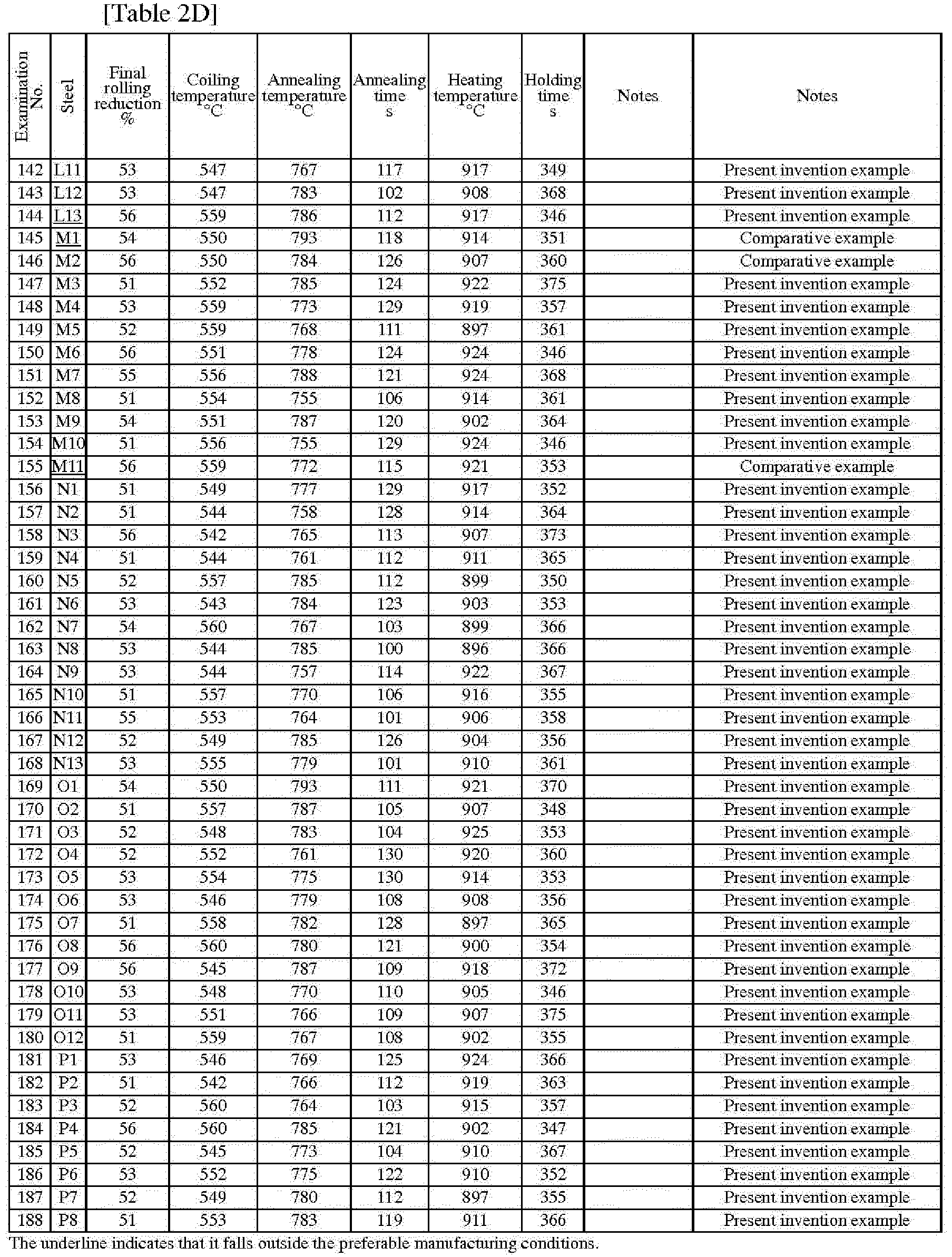


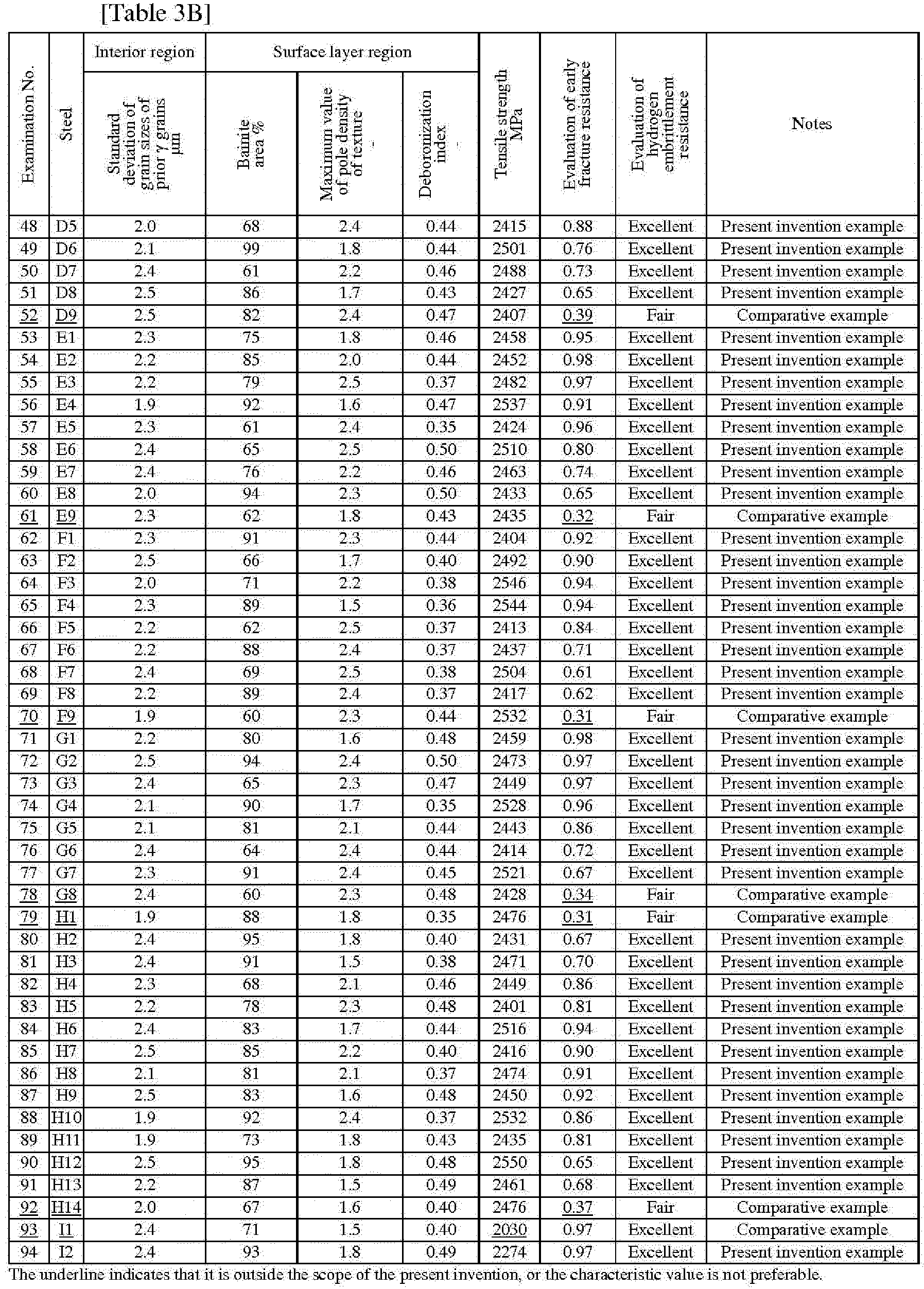


- From Tables 3A to 3H, it can be seen that the hot-stamping formed bodies according to the present invention examples had high strength and excellent hydrogen embrittlement resistance and early fracture resistance. On the other hand, it can be seen that in the hot-stamping formed bodies according to comparative examples, one of the properties deteriorated.
- According to the above-described aspects of the present invention, it is possible to provide a hot-stamping formed body having high strength and excellent hydrogen embrittlement resistance and early fracture resistance.
Claims (2)
- A hot-stamping formed body comprising, as a chemical composition, by mass%:C: more than 0.40% and 0.70% or less;Si: 0.010% to 3.00%;Mn: 0.60% to 3.00%;P: 0.100% or less;S: 0.0100% or less;N: 0.0200% or less;O: 0.0200% or less;Al: 0.0010% to 0.5000%;Nb: 0.0010% to 0.100%;Ti: 0.010% to 0.200%;Cr: 0.01% to 0.80%;Mo: 0.0010% to 1.000%;B: 0.0005% to 0.0200%;Co: 0% to 4.00%;Ni: 0% to 3.00%;Cu: 0% to 3.00%;V: 0% to 3.00%;W: 0% to 3.00%;Ca: 0% to 1.000%;Mg: 0% to 1.000%;REM: 0% to 1.000%;Sb: 0% to 1.000%;Sn: 0% to 1.000%;Zr: 0% to 1.000%;As: 0% to 0.100%; anda remainder: Fe and impurities,in an interior region, which is a region between 4/16 depth of a sheet thickness from a surface of the hot-stamping formed body and 5/16 depth of the sheet thickness from the surface,a standard deviation of grain sizes of prior austenite grains is 5.0 µm or less,in a surface layer region, which is a region between the surface and 1/25 depth of the sheet thickness from the surface,an area ratio of bainite is more than 10%,a maximum value of pole density of a texture is 4.0 or less, anda deboronization index is 0.05 or more.
- The hot-stamping formed body according to claim 1 comprising, as the chemical composition, by mass%, one or more selected from the group consisting of:Co: 0.01% to 4.00%;Ni: 0.01% to 3.00%;Cu: 0.01% to 3.00%;V: 0.01% to 3.00%;W: 0.01% to 3.00%;Ca: 0.001% to 1.000%;Mg: 0.001% to 1.000%;REM: 0.001% to 1.000%;Sb: 0.001% to 1.000%;Sn: 0.001% to 1.000%;Zr: 0.001% to 1.000%; andAs: 0.001% to 0.100%.
Applications Claiming Priority (2)
| Application Number | Priority Date | Filing Date | Title |
|---|---|---|---|
| JP2022067020 | 2022-04-14 | ||
| PCT/JP2023/007855 WO2023199638A1 (en) | 2022-04-14 | 2023-03-02 | Hot-stamp-formed article |
Publications (2)
| Publication Number | Publication Date |
|---|---|
| EP4509241A1 true EP4509241A1 (en) | 2025-02-19 |
| EP4509241A4 EP4509241A4 (en) | 2025-10-15 |
Family
ID=88329346
Family Applications (1)
| Application Number | Title | Priority Date | Filing Date |
|---|---|---|---|
| EP23788060.4A Pending EP4509241A4 (en) | 2022-04-14 | 2023-03-02 | ARTICLE FORMED BY HOT STAMPING |
Country Status (7)
| Country | Link |
|---|---|
| US (1) | US20250101557A1 (en) |
| EP (1) | EP4509241A4 (en) |
| JP (1) | JP7828013B2 (en) |
| KR (1) | KR102928024B1 (en) |
| CN (1) | CN118632941A (en) |
| MX (1) | MX2024009381A (en) |
| WO (1) | WO2023199638A1 (en) |
Family Cites Families (7)
| Publication number | Priority date | Publication date | Assignee | Title |
|---|---|---|---|---|
| CN111655885B (en) * | 2018-03-29 | 2021-11-19 | 日本制铁株式会社 | Hot stamp-molded body |
| CN112930411B (en) | 2018-10-18 | 2022-08-30 | 杰富意钢铁株式会社 | High yield ratio and high strength galvanized steel sheet and method for producing same |
| KR102643398B1 (en) * | 2019-03-20 | 2024-03-07 | 닛폰세이테츠 가부시키가이샤 | hot stamp molding body |
| WO2020213179A1 (en) * | 2019-04-17 | 2020-10-22 | 日本製鉄株式会社 | Steel sheet and method for manufacturing same, and molded article |
| CN115135790B (en) * | 2020-05-13 | 2023-09-22 | 日本制铁株式会社 | Steel plates for hot stamping and hot stamping formed parts |
| JP7436916B2 (en) * | 2020-05-13 | 2024-02-22 | 日本製鉄株式会社 | hot stamp molded body |
| JP2022067020A (en) | 2020-10-19 | 2022-05-02 | 有限会社ノコス | Universal refrigerated-product partition plate for convenience store |
-
2023
- 2023-03-02 KR KR1020247025453A patent/KR102928024B1/en active Active
- 2023-03-02 WO PCT/JP2023/007855 patent/WO2023199638A1/en not_active Ceased
- 2023-03-02 JP JP2024514839A patent/JP7828013B2/en active Active
- 2023-03-02 MX MX2024009381A patent/MX2024009381A/en unknown
- 2023-03-02 CN CN202380019417.XA patent/CN118632941A/en active Pending
- 2023-03-02 EP EP23788060.4A patent/EP4509241A4/en active Pending
- 2023-03-02 US US18/832,024 patent/US20250101557A1/en active Pending
Also Published As
| Publication number | Publication date |
|---|---|
| CN118632941A (en) | 2024-09-10 |
| JPWO2023199638A1 (en) | 2023-10-19 |
| JP7828013B2 (en) | 2026-03-11 |
| KR102928024B1 (en) | 2026-02-19 |
| WO2023199638A1 (en) | 2023-10-19 |
| EP4509241A4 (en) | 2025-10-15 |
| MX2024009381A (en) | 2024-08-09 |
| KR20240130760A (en) | 2024-08-29 |
| US20250101557A1 (en) | 2025-03-27 |
Similar Documents
| Publication | Publication Date | Title |
|---|---|---|
| EP3072987B1 (en) | High-carbon steel sheet and method for producing the same | |
| EP2468911B1 (en) | Hot pressed member, steel sheet for hot pressed member, and method for producing hot pressed member | |
| EP2246456B9 (en) | High-strength steel sheet and process for production thereof | |
| EP3733898A1 (en) | High-strength cold rolled steel sheet and method for manufacturing same | |
| EP3287539A1 (en) | Plated steel plate | |
| EP3951012A1 (en) | Coated steel member, coated steel sheet, and methods for producing same | |
| CN115135790A (en) | Steel sheet for hot stamping and hot stamped molded body | |
| EP3272892A1 (en) | High-strength cold-rolled steel sheet and method for manufacturing same | |
| EP3418417B1 (en) | High-strength cold-rolled steel sheet | |
| EP3282030A1 (en) | Heat-treated steel sheet member, and production method therefor | |
| EP3399064B1 (en) | High-strength cold-rolled steel sheet | |
| EP3106528A1 (en) | High-strength hot-dip galvanized steel sheet, and method for manufacturing high-strength alloyed hot-dip galvanized steel sheet | |
| EP4671398A1 (en) | STEEL SHEET AND MANUFACTURING PROCESSES FOR IT | |
| EP3591087A1 (en) | High strength cold rolled steel sheet and method for producing same | |
| EP3266897A1 (en) | High strength steel sheet and manufacturing method therefor | |
| EP4613899A1 (en) | Galvanized steel sheet and member, and method for producing same | |
| EP4079884A1 (en) | Steel sheet, member, and methods respectively for producing said steel sheet and said member | |
| EP3748030A1 (en) | High-carbon hot-rolled steel sheet and method for manufacturing same | |
| EP4502213B1 (en) | Steel sheet for hot stamping and hot stamped part | |
| EP3141627A1 (en) | Soft-nitriding steel sheet, method for manufacturing same, and soft-nitrided steel | |
| US20250101557A1 (en) | Hot-stamping formed body | |
| EP4600396A1 (en) | High-strength hot-rolled steel sheet and method for producing same | |
| WO2020017607A1 (en) | Steel plate | |
| CN119866384A (en) | Steel sheet, member, and method for producing same | |
| EP4509240A1 (en) | Hot-stamp-formed article |
Legal Events
| Date | Code | Title | Description |
|---|---|---|---|
| STAA | Information on the status of an ep patent application or granted ep patent |
Free format text: STATUS: THE INTERNATIONAL PUBLICATION HAS BEEN MADE |
|
| PUAI | Public reference made under article 153(3) epc to a published international application that has entered the european phase |
Free format text: ORIGINAL CODE: 0009012 |
|
| STAA | Information on the status of an ep patent application or granted ep patent |
Free format text: STATUS: REQUEST FOR EXAMINATION WAS MADE |
|
| 17P | Request for examination filed |
Effective date: 20240731 |
|
| AK | Designated contracting states |
Kind code of ref document: A1 Designated state(s): AL AT BE BG CH CY CZ DE DK EE ES FI FR GB GR HR HU IE IS IT LI LT LU LV MC ME MK MT NL NO PL PT RO RS SE SI SK SM TR |
|
| DAV | Request for validation of the european patent (deleted) | ||
| DAX | Request for extension of the european patent (deleted) | ||
| A4 | Supplementary search report drawn up and despatched |
Effective date: 20250916 |