EP4507330A1 - Heat-sound converter - Google Patents
Heat-sound converter Download PDFInfo
- Publication number
- EP4507330A1 EP4507330A1 EP23784504.5A EP23784504A EP4507330A1 EP 4507330 A1 EP4507330 A1 EP 4507330A1 EP 23784504 A EP23784504 A EP 23784504A EP 4507330 A1 EP4507330 A1 EP 4507330A1
- Authority
- EP
- European Patent Office
- Prior art keywords
- heat
- heat transfer
- sound
- fluid
- passage
- Prior art date
- Legal status (The legal status is an assumption and is not a legal conclusion. Google has not performed a legal analysis and makes no representation as to the accuracy of the status listed.)
- Withdrawn
Links
Images




Classifications
-
- G—PHYSICS
- G10—MUSICAL INSTRUMENTS; ACOUSTICS
- G10K—SOUND-PRODUCING DEVICES; METHODS OR DEVICES FOR PROTECTING AGAINST, OR FOR DAMPING, NOISE OR OTHER ACOUSTIC WAVES IN GENERAL; ACOUSTICS NOT OTHERWISE PROVIDED FOR
- G10K15/00—Acoustics not otherwise provided for
- G10K15/04—Sound-producing devices
-
- F—MECHANICAL ENGINEERING; LIGHTING; HEATING; WEAPONS; BLASTING
- F03—MACHINES OR ENGINES FOR LIQUIDS; WIND, SPRING, OR WEIGHT MOTORS; PRODUCING MECHANICAL POWER OR A REACTIVE PROPULSIVE THRUST, NOT OTHERWISE PROVIDED FOR
- F03G—SPRING, WEIGHT, INERTIA OR LIKE MOTORS; MECHANICAL-POWER PRODUCING DEVICES OR MECHANISMS, NOT OTHERWISE PROVIDED FOR OR USING ENERGY SOURCES NOT OTHERWISE PROVIDED FOR
- F03G7/00—Mechanical-power-producing mechanisms, not otherwise provided for or using energy sources not otherwise provided for
- F03G7/002—Mechanical-power-producing mechanisms, not otherwise provided for or using energy sources not otherwise provided for using the energy of vibration of fluid columns
-
- F—MECHANICAL ENGINEERING; LIGHTING; HEATING; WEAPONS; BLASTING
- F28—HEAT EXCHANGE IN GENERAL
- F28D—HEAT-EXCHANGE APPARATUS, NOT PROVIDED FOR IN ANOTHER SUBCLASS, IN WHICH THE HEAT-EXCHANGE MEDIA DO NOT COME INTO DIRECT CONTACT
- F28D19/00—Regenerative heat-exchange apparatus in which the intermediate heat-transfer medium or body is moved successively into contact with each heat-exchange medium
-
- F—MECHANICAL ENGINEERING; LIGHTING; HEATING; WEAPONS; BLASTING
- F28—HEAT EXCHANGE IN GENERAL
- F28D—HEAT-EXCHANGE APPARATUS, NOT PROVIDED FOR IN ANOTHER SUBCLASS, IN WHICH THE HEAT-EXCHANGE MEDIA DO NOT COME INTO DIRECT CONTACT
- F28D20/00—Heat storage plants or apparatus in general; Regenerative heat-exchange apparatus not covered by groups F28D17/00 or F28D19/00
- F28D20/0056—Heat storage plants or apparatus in general; Regenerative heat-exchange apparatus not covered by groups F28D17/00 or F28D19/00 using solid heat storage material
-
- F—MECHANICAL ENGINEERING; LIGHTING; HEATING; WEAPONS; BLASTING
- F28—HEAT EXCHANGE IN GENERAL
- F28D—HEAT-EXCHANGE APPARATUS, NOT PROVIDED FOR IN ANOTHER SUBCLASS, IN WHICH THE HEAT-EXCHANGE MEDIA DO NOT COME INTO DIRECT CONTACT
- F28D7/00—Heat-exchange apparatus having stationary tubular conduit assemblies for both heat-exchange media, the media being in contact with different sides of a conduit wall
-
- F—MECHANICAL ENGINEERING; LIGHTING; HEATING; WEAPONS; BLASTING
- F28—HEAT EXCHANGE IN GENERAL
- F28D—HEAT-EXCHANGE APPARATUS, NOT PROVIDED FOR IN ANOTHER SUBCLASS, IN WHICH THE HEAT-EXCHANGE MEDIA DO NOT COME INTO DIRECT CONTACT
- F28D7/00—Heat-exchange apparatus having stationary tubular conduit assemblies for both heat-exchange media, the media being in contact with different sides of a conduit wall
- F28D7/0008—Heat-exchange apparatus having stationary tubular conduit assemblies for both heat-exchange media, the media being in contact with different sides of a conduit wall the conduits for one medium being in heat conductive contact with the conduits for the other medium
Definitions
- the present disclosure relates to a heat sound converter.
- a heat sound converter converts heat into sound waves using thermoacoustic phenomena.
- the sound waves produced by the heat sound converter are further converted into other energy such as electricity and used.
- the heat sound converter is configured by arranging a heater, which is a heat exchanger on a heating side, at one end of a heat accumulator through which a working fluid passes as sound waves, and a cooler, which is a heat exchanger on a cooling side, at the other end of the heat accumulator.
- the heat sound converter utilizes a temperature difference generated across the heat accumulator by the fluid flowing through the heater and the fluid flowing through the cooler to amplify the sound waves of the working fluid passing through the heat accumulator.
- Patent Document 1 JP 2020-125877 A
- Patent Document 1 in order to bring the plate portion of the heat exchange member into contact with the channel wall of the stack, a thickness of the plate portion must be made small. Further, in Patent Document 1, in order to bring the tip of the plate portion of the heat exchange member into contact with the channel wall of the stack, the tip is processed into a tapered shape so that it is thinner than the remaining base end. In order to increase the opening area of the minute passage of the stack, it is necessary to reduce the thickness of the channel wall of the stack, and it is necessary to further reduce the thickness of the plate portion of the heat exchange member. For this reason, since the strength of the plate portion of the heat exchange member cannot be ensured, the thickness of the channel wall of the stack cannot be reduced, and it is difficult to increase the opening area of the minute passage of the stack.
- An object of the present disclosure is to provide a heat sound converter that can both secure an opening area of an intermediate sound wave passage of a heat accumulator and promote a heat transfer between at least one of a heater and a cooler and a heat accumulator.
- At least one of the heater and the cooler is provided with a heat transfer portion that is provided on an inner circumferential side of the first outer circumference portion or the second outer circumference portion and divides the first sound wave passage or the second sound wave passage into a plurality of sections.
- a heat transfer wall portion is formed which is thicker than the cell wall and is used to block a portion of the intermediate sound wave passage and conduct heat transfer with the heat transfer portion.
- a heat transfer portion that divides the first sound wave passage or the second sound wave passage into multiple sections is provided on the inner circumferential side of at least one of the first outer circumference portion of the heater and the second outer circumference portion of the cooler. Further, a heat transfer wall portion is formed in the heat accumulator at a position facing the heat transfer portion. The heat transfer wall portion closes a part of the intermediate sound wave passage and is formed to be thicker than the cell wall. Furthermore, by the heat transfer portion and the heat transfer wall portion being in face-to-face contact with each other, it is possible to promote heat transfer between at least one of the heater and the cooler and the heat accumulator.
- the heat sound converter of the above aspect it is possible to both secure the opening area of the intermediate sound wave passage of the heat accumulator and promote heat transfer between the heat accumulator and at least one of the heater and the cooler.
- the heat sound converter 1 of the present embodiment converts heat into sound waves using thermoacoustic phenomena.
- the heat sound converter 1 includes a heater 2, a cooler 3, and a heat accumulator 4.
- the heater 2 includes a first sound wave passage 21 formed on an inner circumferential side of a first outer circumference portion 23 and through which the sound waves pass, and a high temperature side fluid passage 22 formed in the first outer circumference portion 23 and through which the first fluid F1 flows.
- the cooler 3 includes a second sound wave passage 31 formed on an inner circumferential side of the second outer circumference portion 33 and through which the sound waves pass, and a low temperature side fluid passage 32 formed in the second outer circumference portion 33 and through which a second fluid F2 having a lower temperature than the first fluid F1 flows.
- the heat accumulator 4 is disposed between the heater 2 and the cooler 3, and has an intermediate sound wave passage 41 formed between a plurality of cell walls 44 and through which sound waves pass through the first sound wave passage 21 and the second sound wave passage 31.
- a first heat transfer portion 24 that partitions the first sound wave passage 21 into a plurality of sections is provided on the inner circumferential side of the first outer circumference portion 23 of the heater 2. Furthermore, a second heat transfer portion 34 is provided on the inner circumferential side of the second outer circumference portion 33 of the cooler 3 to partition the second sound wave passage 31 into a plurality of sections.
- a heat transfer wall portion 43 is formed for performing heat transfer with the first heat transfer portion 24 of the heater 2 and the second heat transfer portion 34 of the cooler 3.
- the heat transfer wall portion 43 has a thickness greater than a thickness of the cell wall 44 and is formed in a state in which it closes a part of the intermediate sound wave passage 41.
- the heat sound converter 1 of the present embodiment will be explained in detail below.
- thermoacoustic power generation device 5 Heat sound converter 1 and thermoacoustic power generation device 5
- the heat sound converter 1 of the present embodiment constitutes a thermoacoustic power generation device 5 that generates power by utilizing sound waves.
- One or more heat sound converters 1 are disposed midway through a piping that constitutes the thermoacoustic power generation device 5.
- the thermoacoustic power generation device 5 of the present embodiment is of a loop type, and includes an annular pipe 51 formed in an annular shape, a heat sound converter 1 disposed in the middle of the annular pipe 51, and a generator 53 connected to a branch pipe 52 branched from the annular pipe 51.
- the heat sound converter 1 is used to amplify sound waves caused by a working fluid F0 circulating in the annular pipe 51.
- the heat sound converter 1 amplifies the sound waves caused by the working fluid F0 by expanding and contracting the working fluid F0, which is a gas, using the temperature difference between both ends of the heat accumulator 4 in an axial direction L.
- the temperature difference between both ends of the heat accumulator in the axial direction L is generated by heating the heat accumulator 4 and the working fluid F0 by the first fluid F1 in the heater 2 and cooling the heat accumulator 4 and the working fluid F0 by the second fluid F2 in the cooler 3.
- the generator 53 is constituted by a linear generator that converts vibrations caused by sound waves into electricity using electromagnetic induction.
- the sound waves amplified by the heat sound converter 1 are then utilized by the generator 53 and converted into electricity.
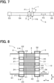
- thermoacoustic power generation device 5 may be of a straight tube type that includes a straight pipe 54, which is a piping formed in a straight line, a heat sound converter 1 arranged midway along the straight pipe 54, a sound wave generator 55 connected to one end of the straight pipe 54, and a generator 53 connected to the other end of the straight pipe 54.
- the first fluid F1 in the present embodiment utilizes an exhaust heat of exhaust gas G supplied from an exhaust heat source 6.
- the first fluid F1 is a heat transfer oil that exchanges heat with the exhaust gas G discharged from the exhaust heat source 6 to an exhaust pipe 61 and is heated by the exhaust heat of the exhaust gas G.
- a heat exchanger 62 for exchanging heat between the exhaust gas G and the heat transfer oil is disposed in the exhaust pipe 61.
- the exhaust heat source 6 includes a firing furnace, an aluminum melting furnace, and the like, for example, as an industrial furnace that heats by burning fuel.
- the exhaust heat source 6 may be any of various facilities that emit exhaust gas G due to combustion.
- the second fluid F2 is circulating water used in a factory.
- Various fluids having a temperature lower than that of the exhaust gas G may be used as the second fluid F2.
- the temperature of the second fluid F2 is lower than the temperature of the working fluid F0.
- An inert gas such as helium or argon is used as the working fluid F0 of the heat sound converter 1 and the thermoacoustic power generation device 5 of the present embodiment.
- a direction along a central axis O of the heat accumulator 4 is referred to as an axial direction L
- a direction around the central axis O of the heat accumulator 4 is referred to as a circumferential direction C
- a radial direction centered on the central axis O of the heat accumulator 4 is referred to as a radial direction R.
- the central axis O of the heater 2 and the central axis O of the cooler 3 are coaxial with the central axis O of the heat accumulator 4, and the central axis O of the heat accumulator 4 also indicates the central axis O of the heater 2 and the central axis O of the cooler 3.
- the heat accumulator 4 has an outer peripheral wall portion 42 that constitutes the wall portion on the outer circumferential side, a plurality of heat transfer wall portions 43 that are bridged across the outer peripheral wall portion 42 on the inner peripheral side of the outer peripheral wall portion 42, and a cell wall 44 that forms a plurality of through holes 45 along the axial direction L on the inner circumferential side of the outer peripheral wall portion 42.
- the outer peripheral wall portion 42 is formed in a cylindrical shape.
- a plurality of the heat transfer wall portions 43 are arranged in parallel from one side to the other side in the radial direction R of the outer peripheral wall portion 42.
- the heat transfer wall portion 43 of the present embodiment is made of the same material as the cell wall 44 and is continuously formed over the entire length of the heat accumulator 4 in the axial direction L. With this configuration, the heat transfer wall portion 43 of the heat accumulator 4 continuously contacts the first heat transfer portion 24 of the heater 2 and the second heat transfer portion 34 of the cooler 3, and the heat transfer between the heat accumulator 4 and the heater 2 and between the heat accumulator 4 and the cooler 3 can be promoted.
- the heat transfer wall portion 43 is formed in contact with the first heat transfer portion 24 of the heater 2 and the second heat transfer portion 34 of the cooler 3.
- the thickness of the heat transfer wall portion 43 may be, for example, 10 to 500 times the thickness of the cell wall 44.
- the cell wall 44 is formed as a polygonal wall portion such as a lattice shape or a honeycomb shape.
- the cell wall 44 is formed continuously over the entire length of the heat accumulator 4 in the axial direction L.
- the thickness of the cell wall 44 may be, for example, 1/10 to 1/2 times the width of a through hole 45.
- the heat accumulator 4 is made of a ceramic material.
- the heat accumulator 4 may be made of a metal material.
- the intermediate sound wave passage 41 of the heat accumulator 4 is formed by a plurality of through holes 45 surrounded by the cell wall 44, the outer peripheral wall portion 42 and the heat transfer wall portion 43. Most of the through holes 45 are formed surrounded by intersecting cell walls 44.
- the opening ratio of the heat accumulator 4 is expressed as the opening area of the intermediate sound wave passage 41 in the cross-sectional area of the cross section perpendicular to the axial direction L of the heat accumulator 4, in other words, the total opening area of the plurality of through holes 45.
- the cell wall 44 and the heat transfer wall portion 43 of the present embodiment are formed so that the opening ratio of the heat accumulator 4 is within the range of 50 to 90%.
- the heater 2 has a first outer circumference portion 23 formed in an annular shape, and a first heat transfer portion 24 formed on the inner circumferential side of the first outer circumference portion 23, with multiple portions arranged in parallel, from one side to the other side in the radial direction R of the first outer circumference portion 23.
- a high temperature side fluid passage 22 through which the first fluid F1 flows is formed in an annular shape.
- a first fluid passage inlet 221 is formed on one side of the first outer circumference portion 23 in the radial direction R for allowing the first fluid F1 to flow into the high temperature side fluid passage 22, and a first fluid passage outlet 222 is formed on the other side of the first outer circumference portion 23 in the radial direction R for allowing the first fluid F1 to flow out from the high temperature side fluid passage 22.
- the first fluid passage inlet 221 and the first fluid passage outlet 222 are formed at positions that are out of phase with each other by 180° in the circumferential direction C.
- a plurality of first heat transfer portions 24 of the heater 2 are formed in a state of facing and contacting a plurality of the heat transfer wall portions 43 of the heat accumulator 4.
- the first heat transfer portion 24 in the present embodiment is formed into a solid shape.
- the shape of a cross section perpendicular to the axial direction L of the first heat transfer portion 24 is substantially the same as the shape of a cross section perpendicular to the axial direction L of the heat transfer wall portion 43.
- the width of the first heat transfer portion 24 is approximately the same as the width of the heat transfer wall portion 43 of the heat accumulator 4.
- the width of the first heat transfer portion 24 may be the same as the width of the heat transfer wall portion 43, and may be appropriately determined within a range not exceeding the width of the heat transfer wall portion 43.
- the first sound wave passage 21 of the heater 2 is formed as an opening portion surrounded by the first outer circumference portion 23 and the first heat transfer portion 24.
- the first sound wave passage 21 is formed at a position facing the cell wall 44 and the through hole 45 of the heat accumulator 4 in the axial direction L.
- the first outer circumference portion 23 and the first heat transfer portion 24 are heated. Then, the working fluid F0 passing through the first sound wave passage 21 is heated by heat transfer from the first outer circumference portion 23 and the first heat transfer portion 24, and the heat accumulator 4 is heated by the first outer circumference portion 23 and the heat transfer wall portion 43 of the heat accumulator 4 is heated by the first heat transfer portion 24. Furthermore, the first fluid F1 used for heating flows out from the high temperature side fluid passage 22 to the first fluid passage outlet 222.
- the cooler 3 has a second outer circumference portion 33 formed in an annular shape, and a second heat transfer portion 34 formed on the inner circumferential side of the second outer circumference portion 33, with multiple portions arranged in parallel, from one side to the other side in the radial direction R of the second outer circumference portion 33.
- FIG. 6 shows the heater 2, but the cooler 3 has a similar structure to the heater 2.
- a low-temperature side fluid passage 32 through which the second fluid F2 flows is formed in an annular shape.
- a second fluid passage inlet 321 is formed on one side of the second outer circumference portion 33 in the radial direction R for allowing the second fluid F2 to flow into the low temperature side fluid passage 32
- a second fluid passage outlet 322 is formed on the other side of the second outer circumference portion 33 in the radial direction R for allowing the second fluid F2 to flow out from the low temperature side fluid passage 32.
- the second fluid passage inlet 321 and the second fluid passage outlet 322 are formed at positions that are out of phase with each other by 180° in the circumferential direction C.
- a plurality of second heat transfer portions 34 of the cooler 3 are formed in a state of facing and contacting a plurality of the heat transfer wall portions 43 of the heat accumulator 4.
- the second heat transfer portion 34 in the present embodiment is formed into a solid shape.
- the shape of a cross section perpendicular to the axial direction L of the second heat transfer portion 34 is substantially the same as the shape of a cross section perpendicular to the axial direction L of the heat transfer wall portion 43.
- the width of the second heat transfer portion 34 is approximately the same as the width of the heat transfer wall portion 43 of the heat accumulator 4.
- the width of the second heat transfer portion 34 may be the same as the width of the heat transfer wall portion 43, and may be appropriately determined within a range not exceeding the width of the heat transfer wall portion 43.
- the second sound wave passage 31 of the cooler 3 is formed as an opening portion surrounded by the second outer circumference portion 33 and the second heat transfer portion 34.
- the second sound wave passage 31 is formed at a position facing the cell wall 44 and the through hole 45 of the heat accumulator 4 in the axial direction L.
- the second outer circumference portion 33 and the second heat transfer portion 34 are cooled.
- the working fluid F0 passing through the second sound wave passage 31 is cooled by heat transfer to the second outer circumference portion 33 and the second heat transfer portion 34, and the heat accumulator 4 is cooled by the second outer circumference portion 33 and the heat transfer wall portion 43 of the heat accumulator 4 is cooled by the second heat transfer portion 34.
- the second fluid F2 used for cooling flows out from the low temperature side fluid passage 32 to the second fluid passage outlet 322.
- the heater 2 and the cooler 3 used in the present embodiment have the same shape.
- the first heat transfer portion 24 of the heater 2 and the second heat transfer portion 34 of the cooler 3 are formed in the same shape.
- the first heat transfer portion 24 that divides the first sound wave passage 21 into multiple sections is provided on the inner circumferential side of the first outer circumference portion 23 of the heater 2, and a second heat transfer portion 34 that divides the second sound wave passage 31 into multiple sections is provided on the inner circumferential side of the second outer circumference portion 33 of the cooler 3.
- the heat transfer wall portion 43 is formed at a position facing the first heat transfer portion 24 and the second heat transfer portion 34.
- the heat transfer wall portion 43 closes a part of the intermediate sound wave passage 41 and is formed to be thicker than the cell wall 44.
- the first heat transfer portion 24 and the second heat transfer portion 34 face and contact the heat transfer wall portion 43, thereby facilitating heat transfer between the heater 2 and the cooler 3 and the heat accumulator 4.
- the thickness of the multiple cell walls 44 in the heat accumulator 4 can be reduced, thereby ensuring the opening area of the intermediate sound wave passage 41 of the heat accumulator 4.
- the heat sound converter 1 of the present embodiment it is possible to ensure the opening area of the intermediate sound wave passage 41 of the heat accumulator 4 while promoting heat transfer between the heater 2 and the cooler 3, and the heat accumulator 4.
- the opening area of the intermediate sound wave passage 41 it is possible to appropriately ensure the efficiency of heat sound conversion for converting heat into sound.
- the heat transfer wall portion 43 is thick, so that heat transfer between the heater 2 and the cooler 3, and the heat accumulator 4 can be effectively performed. Furthermore, since the first heat transfer portion 24 of the heater 2 and the second heat transfer portion 34 of the cooler 3 are formed in the same cross-sectional shape as the heat transfer wall portion 43, the intermediate sound wave passage 41 of the heat accumulator 4 is not blocked by the first heat transfer portion 24 and the second heat transfer portion 34.
- the configuration of the heat sound converter 1 of the present embodiment makes it possible to maximize the heat sound conversion efficiency.
- One of the first heat transfer portion 24 of the heater 2 and the second heat transfer portion 34 of the cooler 3 does not necessarily have to be formed.
- the heat transfer portion in contact with the heat transfer wall portion 43 of the heat accumulator 4 may be formed on only one of the heater 2 and the cooler 3.
- the structures of the first heat transfer portion 24 of the heater 2 and the second heat transfer portion 34 of the cooler 3 are different from those in the first embodiment.
- a first branch fluid passage 25 is formed, which is branched from the high temperature side fluid passage 22 of the first outer circumference portion 23 and through which the first fluid F1 flows.
- the first fluid F 1 flowing into the high temperature side fluid passage 22 from the first fluid passage inlet 221 flows through the high temperature side fluid passage 22 and branches off from the high temperature side fluid passage 22 to flow into a plurality of first branch fluid passages 25.
- the first fluid F1 flowing through the high temperature side fluid passage 22 and the first fluid F1 flowing through the multiple first branch fluid passages 25 join together near the first fluid passage outlet 222 and flow out from the first fluid passage outlet 222.
- a second branch fluid passage 35 is formed which branches off from the low temperature side fluid passage 32 of the second outer circumference portion 33 and through which the second fluid F2 flows.
- FIG. 10 shows the heater 2, but the cooler 3 has a similar structure to the heater 2.
- the second fluid F 2 flowing into the low temperature side fluid passage 32 from the second fluid passage inlet 321 flows through the low temperature side fluid passage 32 and branches off from the low temperature side fluid passage 32 to flow into a plurality of second branch fluid passages 35.
- the second fluid F2 flowing through the low temperature side fluid passage 32 and the second fluid F2 flowing through the multiple second branch fluid passages 35 join together near the second fluid passage outlet 322 and flow out from the second fluid passage outlet 322.
- the first heat transfer portion 24 reduces the temperature distribution in a cross section perpendicular to the axial direction L in the heater 2, and the second heat transfer portion 34 reduces the temperature distribution in a cross section perpendicular to the axial direction L in the cooler 3.
- the first fluid F1 flowing through the first branch fluid passage 25 can raise the temperature of the first heat transfer portion 24 of the heater 2 to a higher temperature. Heat transfer from the first heat transfer portion 24 of the heater 2 to the heat transfer wall portion 43 of the heat accumulator 4 can be further promoted.
- the second fluid F2 flowing through the second branch fluid passage 35 can lower the temperature of the second heat transfer portion 34 of the cooler 3. This can further promote heat transfer from the heat transfer wall portion 43 of the heat accumulator 4 to the second heat transfer portion 34 of the cooler 3.
- the branch fluid passage may be formed only in either the first heat transfer portion 24 of the heater 2 or the second heat transfer portion 34 of the cooler 3.
- each branch fluid passage 25, 35 in the present embodiment may be applied to the configuration of a heat sound converter 1 using a heat accumulator 4 of a third embodiment described later, or the configuration of a heat sound converter 1 using each thermal conductive material 461, 462 of a fourth embodiment described later.
- the structure of the heat transfer wall portion 43 of the heat accumulator 4 is different from that of the first embodiment.
- the heat transfer wall portion 43 of the heat accumulator 4 is formed of the same material as the cell wall 44 at the end of the heat accumulator 4 in the axial direction L that faces the first heat transfer portion 24 and the second heat transfer portion 34.
- the heat transfer wall portions 43 in the present embodiment are formed as parts of the heat accumulator 4 at both ends in the axial direction L of the heat accumulator 4. In other words, the heat transfer wall portion 43 is divided into a portion that faces and contacts the first heat transfer portion 24 of the heater 2 and a portion that faces and contacts the second heat transfer portion 34 of the cooler 3.
- the heat transfer wall portion 43 in the present embodiment is formed by filling both ends in the axial direction L of the through hole 45 surrounded by the cell wall 44 with a ceramic material of the same quality as the ceramic material constituting the heat accumulator 4.
- the heat transfer wall portion 43 is formed by filling a paste-like ceramic material into both ends of the axial direction L of the through hole 45 of the cell wall 44 located in a position facing the first heat transfer portion 24 and the second heat transfer portion 34 in the heat accumulator 4.
- the outer peripheral wall portion 42, the cell walls 44 and the heat transfer wall portion 43 of the heat accumulator 4 are made of the same ceramic material.
- the heat transfer wall portion 43 can be formed in a simple manner. Therefore, the heat transfer wall portion 43 is easy to form, and it is possible to achieve both ensuring the opening area of the intermediate sound wave passage 41 of the heat accumulator 4 and ensuring heat transfer between the heater 2 and the cooler 3, and the heat accumulator 4 with simple ingenuity.
- the heat transfer wall portion 43 in the present embodiment may be formed only at one end portion in the axial direction L of the heat accumulator 4.
- the heat transfer wall portion 43 may be formed so as to face and come into contact only with the first heat transfer portion 24 of the heater 2, or may be formed so as to face and come into contact only with the second heat transfer portion 34 of the cooler 3.
- the configuration of the heat transfer wall portion 43 of the heat accumulator 4 of the present embodiment is applied to the heat sound converter 1 in which the branch fluid passages 25, 35 are formed in the heater 2 and the cooler 3 of the second embodiment.
- the configuration of the heat transfer wall portion 43 of the heat accumulator 4 of the present embodiment may be applied to the heat sound converter 1 of the first embodiment in which the heater 2 and the cooler 3 are not formed with the branch fluid passages 25, 35.
- a separate member is disposed between the heater 2 and the cooler 3, and the heat accumulator 4.
- a first thermal conductive material 461 made of a material softer than the material constituting the first heat transfer portion 24 and the material constituting the heat transfer wall portion 43 is sandwiched between the first heat transfer portion 24 of the heater 2 and the heat transfer wall portion 43 of the heat accumulator 4.
- a second thermal conductive material 462 made of a material softer than the material constituting the second heat transfer portion 34 and the material constituting the heat transfer wall portion 43 is sandwiched between the second heat transfer portion 34 of the cooler 3 and the heat transfer wall portion 43 of the heat accumulator 4.
- the first heat transfer portion 24 of the heater 2 and the second heat transfer portion 34 of the cooler 3 are made of a metal material
- the heat transfer wall portion 43 of the heat accumulator 4 is made of a ceramic material.
- the thermal conductive materials 461, 462 arranged between the heater 2 and the heat accumulator 4, and between the cooler 3 and the heat accumulator 4, are made of a metal material, a polymer material, or the like that is softer than metal materials and ceramic materials.
- Each of the thermal conductive materials 461 and 462 is formed in the form of a sheet or gel as a heat transfer sheet or gel.
- the cross-sectional shape of the first thermal conductive material 461 in the present embodiment perpendicular to the axial direction L is approximately the same as the cross-sectional shape of the first heat transfer portion 24 perpendicular to the axial direction L and the cross-sectional shape of the heat transfer wall portion 43 perpendicular to the axial direction L.
- the cross-sectional shape of the second thermal conductive material 462 perpendicular to the axial direction L is approximately the same as the cross-sectional shape of the second heat transfer portion 34 perpendicular to the axial direction L and the cross-sectional shape of the heat transfer wall portion 43 perpendicular to the axial direction L.
- Each of the thermal conductive materials 461 and 462 is used to achieve close contact between the heater 2 and the heat accumulator 4 and between the cooler 3 and the heat accumulator 4.
- minute irregularities which are expressed as surface roughness, are formed on the end surface in the axial direction L of the first heat transfer portion 24 of the heater 2, the end surface in the axial direction L of the second heat transfer portion 34 of the cooler 3, and the end surface in the axial direction L of the heat transfer wall portion 43 of the heat accumulator 4. Therefore, the contact surfaces between the first heat transfer portion 24 and the heat transfer wall portion 43 and between the second heat transfer portion 34 and the heat transfer wall portion 43 may be in a point contact state when observed microscopically. In this case, there is a risk that the heat transfer between the first heat transfer portion 24 and the second heat transfer portion 34, and the heat transfer wall portion 43 will decrease due to an increase in contact thermal resistance.
- each thermal conductive material 461, 462 between the first heat transfer portion 24 and the heat transfer wall portion 43 and between the second heat transfer portion 34 and the heat transfer wall portion 43, it is possible to fill in the unevenness at the contact surface between the first heat transfer portion 24 and the heat transfer wall portion 43 and between the second heat transfer portion 34 and the heat transfer wall portion 43, thereby improving the heat transfer at the contact surface.
- thermal conductive materials 461 and 462 in the present embodiment may be disposed only between the heater 2 and the heat accumulator 4 or between the cooler 3 and the heat accumulator 4.
- the configuration of the thermal conductive materials 461 and 462 of the present embodiment is applied to the heat sound converter 1 in which the branch fluid passages 25 and 35 are formed in the heater 2 and the cooler 3 of the second embodiment.
- the configuration of the thermal conductive materials 461, 462 of the present embodiment may be applied to the heat sound converter 1 of the first embodiment in which the branch fluid passages 25, 35 are not formed in the heater 2 and the cooler 3.
- a heat sound converter (1) for converting heat into sound waves by utilizing a thermoacoustic phenomenon includes
- At least one of the heater and the cooler is provided with a heat transfer portion (24, 34) that is provided on an inner circumferential side of the first outer circumference portion or the second outer circumference portion and divides the first sound wave passage or the second sound wave passage into a plurality of sections.
- a heat transfer wall portion (43) is formed which is thicker than the cell wall and is used to block a portion of the intermediate sound wave passage and conduct heat transfer with the heat transfer portion.
- the heat transfer wall portion is formed of the same material as the cell wall over an entire length of the heat accumulator in the axial direction.
- the heat transfer wall portion is formed of the same material as the cell wall at an end portion of the heat accumulator in the axial direction opposite to the heat transfer portion.
- a thermal conductive material (461, 462) made of a material softer than the material constituting the heat transfer portion and the material constituting the heat transfer wall portion is sandwiched between the heat transfer portion and the heat transfer wall portion.
- a branch fluid passage (25, 35) is formed inside the heat transfer portion, branching from the high temperature side fluid passage or the low temperature side fluid passage and through which the first fluid or the second fluid flows.
- the first fluid utilizes exhaust heat of exhaust gas (G) supplied from an exhaust heat source (6), and the heat sound converter constitutes a thermoacoustic power generation device (5) that generates power by utilizing the sound waves.
- the present disclosure is not limited to each embodiment, and it is possible to configure further different embodiments without departing from the gist of the present disclosure. Further, the present disclosure includes various modifications, modifications within the equivalence, and the like. Furthermore, the technical idea of the present disclosure further includes various combinations and various forms of constitutional elements that are derivable from the present disclosure.
Landscapes
- Engineering & Computer Science (AREA)
- Physics & Mathematics (AREA)
- Mechanical Engineering (AREA)
- General Engineering & Computer Science (AREA)
- Thermal Sciences (AREA)
- Acoustics & Sound (AREA)
- Multimedia (AREA)
- Chemical & Material Sciences (AREA)
- Combustion & Propulsion (AREA)
- Heat-Exchange Devices With Radiators And Conduit Assemblies (AREA)
- Secondary Cells (AREA)
- Cooling Or The Like Of Semiconductors Or Solid State Devices (AREA)
Abstract
Description
- This application is based on
Japanese Patent Application No. 2022-063441 filed on April 6, 2022 - The present disclosure relates to a heat sound converter.
- A heat sound converter converts heat into sound waves using thermoacoustic phenomena. The sound waves produced by the heat sound converter are further converted into other energy such as electricity and used. The heat sound converter is configured by arranging a heater, which is a heat exchanger on a heating side, at one end of a heat accumulator through which a working fluid passes as sound waves, and a cooler, which is a heat exchanger on a cooling side, at the other end of the heat accumulator. The heat sound converter utilizes a temperature difference generated across the heat accumulator by the fluid flowing through the heater and the fluid flowing through the cooler to amplify the sound waves of the working fluid passing through the heat accumulator.
- In order to improve the heat sound conversion efficiency in the heat sound converter, it is necessary to ensure an opening area (opening ratio) of a passage through which the working fluid passes in the heat accumulator, as well as it is important to effectively exchange heat between the fluid and the working fluid in the heater and between the fluid and the working fluid in the cooler. For example, in a heat exchange member of
Patent Document 1, when the heat sound converter is configured by a stack (heat accumulator) and a heat exchange member (heat exchanger), the channel walls forming the plurality of minute passages in the stack are brought into proper contact with a plate portion of the heat exchange member. Furthermore, the minute passages through which the working fluid in the stack passes are arranged not to overlap with the plate portions of the heat exchange member, so that the opening area of the minute passages is not reduced. - Patent Document 1:
JP 2020-125877 A - In
Patent Document 1, in order to bring the plate portion of the heat exchange member into contact with the channel wall of the stack, a thickness of the plate portion must be made small. Further, inPatent Document 1, in order to bring the tip of the plate portion of the heat exchange member into contact with the channel wall of the stack, the tip is processed into a tapered shape so that it is thinner than the remaining base end. In order to increase the opening area of the minute passage of the stack, it is necessary to reduce the thickness of the channel wall of the stack, and it is necessary to further reduce the thickness of the plate portion of the heat exchange member. For this reason, since the strength of the plate portion of the heat exchange member cannot be ensured, the thickness of the channel wall of the stack cannot be reduced, and it is difficult to increase the opening area of the minute passage of the stack. - An object of the present disclosure is to provide a heat sound converter that can both secure an opening area of an intermediate sound wave passage of a heat accumulator and promote a heat transfer between at least one of a heater and a cooler and a heat accumulator.
- According to an aspect of the present disclosure,
- a heat sound converter for converting heat into sound waves by utilizing a thermoacoustic phenomenon includes
- a heater having a first sound wave passage formed on an inner circumferential side of a first outer circumference portion and through which the sound waves pass, and a high temperature side fluid passage formed on the first outer circumference portion and through which a first fluid flows,
- a cooler having a second sound wave passage formed on an inner circumferential side of a second outer circumference portion through which the sound waves pass, and a low temperature side fluid passage formed on the second outer circumference portion and through which a second fluid having a temperature lower than that of the first fluid flows, and
- a heat accumulator disposed between the heater and the cooler, having an intermediate sound wave passage formed between a plurality of cell walls through which the sound waves pass via the first sound wave passage and the second sound wave passage.
- At least one of the heater and the cooler is provided with a heat transfer portion that is provided on an inner circumferential side of the first outer circumference portion or the second outer circumference portion and divides the first sound wave passage or the second sound wave passage into a plurality of sections.
- In the heat accumulator, at a position facing the heat transfer portion in a cross section perpendicular to an axial direction along a direction in which the intermediate sound wave passage is formed, a heat transfer wall portion is formed which is thicker than the cell wall and is used to block a portion of the intermediate sound wave passage and conduct heat transfer with the heat transfer portion.
- In the heat sound converter of one aspect described above, a heat transfer portion that divides the first sound wave passage or the second sound wave passage into multiple sections is provided on the inner circumferential side of at least one of the first outer circumference portion of the heater and the second outer circumference portion of the cooler. Further, a heat transfer wall portion is formed in the heat accumulator at a position facing the heat transfer portion. The heat transfer wall portion closes a part of the intermediate sound wave passage and is formed to be thicker than the cell wall. Furthermore, by the heat transfer portion and the heat transfer wall portion being in face-to-face contact with each other, it is possible to promote heat transfer between at least one of the heater and the cooler and the heat accumulator.
- In addition, there is no need to face the heat transfer portion to the cell wall, and there is no need to ensure a large thickness for the cell wall. Therefore, while ensuring the strength of the heat transfer portion of at least one of the heater and the cooler and the strength of the heat transfer wall portion of the heat accumulator, the thickness of the plurality of cell walls in the heat accumulator is reduced, and the opening area of the intermediate sound wave passage of the heat accumulator can be secured.
- Therefore, according to the heat sound converter of the above aspect, it is possible to both secure the opening area of the intermediate sound wave passage of the heat accumulator and promote heat transfer between the heat accumulator and at least one of the heater and the cooler.
- The above and other objects, features and advantages of the present disclosure will become more apparent from the following detailed description made with reference to the accompanying drawings. In the drawings:
-
FIG. 1 is an explanatory diagram showing a loop-type thermoacoustic power generation device according to a first embodiment; -
FIG. 2 is a sectional view taken along a line II-II inFIG. 6 , showing a heat sound converter according to the first embodiment; -
FIG. 3 is a cross-sectional view taken along a line III-III inFIG. 6 , showing the heat sound converter according to the first embodiment; -
FIG. 4 is a cross-sectional view taken along a line IV-IV inFIG. 2 , showing a heat accumulator of the heat sound converter according to the first embodiment; -
FIG. 5 is an enlarged cross-sectional view of a portion inFIG. 4 according to the first embodiment; -
FIG. 6 is a sectional view taken along a line VI-VI inFIG. 2 , showing a heater of the heat sound converter according to the first embodiment; -
FIG. 7 is an explanatory diagram showing a straight tube type thermoacoustic power generation device according to the first embodiment; -
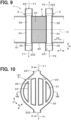
FIG. 8 is a cross-sectional view taken along a line VIII-VIII inFIG. 10 , showing a heat sound converter according to a second embodiment; -
FIG. 9 is a sectional view taken along a line IX-IX inFIG. 10 , showing the heat sound converter according to the second embodiment; -
FIG. 10 is a cross-sectional view taken along a line X-X inFIG. 8 , showing a heater of the heat sound converter according to the second embodiment; -
FIG. 11 is a cross-sectional view corresponding to the cross section taken along the line II-II inFIG. 6 , showing the heat sound converter according to a third embodiment; -
FIG. 12 is a cross-sectional view corresponding to the cross section taken along the line III-III inFIG. 6 , showing the heat sound converter according to the third embodiment; -
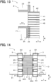
FIG. 13 is an enlarged cross-sectional view of a portion inFIG. 11 according to the third embodiment; -
FIG. 14 is a cross-sectional view corresponding to the cross section taken along the line II-II inFIG. 6 , showing the heat sound converter according to a fourth embodiment; and -
FIG. 15 is an enlarged cross-sectional view of a portion inFIG. 14 according to the fourth embodiment. - A preferred embodiment of the above-mentioned heat sound converter will be described with reference to the drawings.
- As shown in
FIGS. 2 to 6 , theheat sound converter 1 of the present embodiment converts heat into sound waves using thermoacoustic phenomena. Theheat sound converter 1 includes aheater 2, acooler 3, and aheat accumulator 4. Theheater 2 includes a firstsound wave passage 21 formed on an inner circumferential side of a firstouter circumference portion 23 and through which the sound waves pass, and a high temperatureside fluid passage 22 formed in the firstouter circumference portion 23 and through which the first fluid F1 flows. Thecooler 3 includes a secondsound wave passage 31 formed on an inner circumferential side of the secondouter circumference portion 33 and through which the sound waves pass, and a low temperatureside fluid passage 32 formed in the secondouter circumference portion 33 and through which a second fluid F2 having a lower temperature than the first fluid F1 flows. Theheat accumulator 4 is disposed between theheater 2 and thecooler 3, and has an intermediatesound wave passage 41 formed between a plurality ofcell walls 44 and through which sound waves pass through the firstsound wave passage 21 and the secondsound wave passage 31. - A first
heat transfer portion 24 that partitions the firstsound wave passage 21 into a plurality of sections is provided on the inner circumferential side of the firstouter circumference portion 23 of theheater 2. Furthermore, a secondheat transfer portion 34 is provided on the inner circumferential side of the secondouter circumference portion 33 of thecooler 3 to partition the secondsound wave passage 31 into a plurality of sections. As shown inFIG. 5 , in theheat accumulator 4, at a position facing eachheat transfer portion sound wave passage 41, a heattransfer wall portion 43 is formed for performing heat transfer with the firstheat transfer portion 24 of theheater 2 and the secondheat transfer portion 34 of thecooler 3. The heattransfer wall portion 43 has a thickness greater than a thickness of thecell wall 44 and is formed in a state in which it closes a part of the intermediatesound wave passage 41. - The
heat sound converter 1 of the present embodiment will be explained in detail below. - As shown in
FIG. 1 , theheat sound converter 1 of the present embodiment constitutes a thermoacousticpower generation device 5 that generates power by utilizing sound waves. One or moreheat sound converters 1 are disposed midway through a piping that constitutes the thermoacousticpower generation device 5. The thermoacousticpower generation device 5 of the present embodiment is of a loop type, and includes anannular pipe 51 formed in an annular shape, aheat sound converter 1 disposed in the middle of theannular pipe 51, and agenerator 53 connected to abranch pipe 52 branched from theannular pipe 51. - The
heat sound converter 1 is used to amplify sound waves caused by a working fluid F0 circulating in theannular pipe 51. Theheat sound converter 1 amplifies the sound waves caused by the working fluid F0 by expanding and contracting the working fluid F0, which is a gas, using the temperature difference between both ends of theheat accumulator 4 in an axial direction L. The temperature difference between both ends of the heat accumulator in the axial direction L is generated by heating theheat accumulator 4 and the working fluid F0 by the first fluid F1 in theheater 2 and cooling theheat accumulator 4 and the working fluid F0 by the second fluid F2 in thecooler 3. - The
generator 53 is constituted by a linear generator that converts vibrations caused by sound waves into electricity using electromagnetic induction. The sound waves amplified by theheat sound converter 1 are then utilized by thegenerator 53 and converted into electricity. - In addition, as shown in
Figure 7 , the thermoacousticpower generation device 5 may be of a straight tube type that includes astraight pipe 54, which is a piping formed in a straight line, aheat sound converter 1 arranged midway along thestraight pipe 54, asound wave generator 55 connected to one end of thestraight pipe 54, and agenerator 53 connected to the other end of thestraight pipe 54. - As shown in
FIG. 1 , the first fluid F1 in the present embodiment utilizes an exhaust heat of exhaust gas G supplied from anexhaust heat source 6. Specifically, the first fluid F1 is a heat transfer oil that exchanges heat with the exhaust gas G discharged from theexhaust heat source 6 to anexhaust pipe 61 and is heated by the exhaust heat of the exhaust gas G. Aheat exchanger 62 for exchanging heat between the exhaust gas G and the heat transfer oil is disposed in theexhaust pipe 61. - The
exhaust heat source 6 includes a firing furnace, an aluminum melting furnace, and the like, for example, as an industrial furnace that heats by burning fuel. Theexhaust heat source 6 may be any of various facilities that emit exhaust gas G due to combustion. In the present embodiment, the second fluid F2 is circulating water used in a factory. Various fluids having a temperature lower than that of the exhaust gas G may be used as the second fluid F2. Further, the temperature of the second fluid F2 is lower than the temperature of the working fluid F0. An inert gas such as helium or argon is used as the working fluid F0 of theheat sound converter 1 and the thermoacousticpower generation device 5 of the present embodiment. - In the present embodiment, a direction along a central axis O of the
heat accumulator 4 is referred to as an axial direction L, a direction around the central axis O of theheat accumulator 4 is referred to as a circumferential direction C, and a radial direction centered on the central axis O of theheat accumulator 4 is referred to as a radial direction R. The central axis O of theheater 2 and the central axis O of thecooler 3 are coaxial with the central axis O of theheat accumulator 4, and the central axis O of theheat accumulator 4 also indicates the central axis O of theheater 2 and the central axis O of thecooler 3. - As shown in
FIGS 2 ,4 and5 , theheat accumulator 4 has an outerperipheral wall portion 42 that constitutes the wall portion on the outer circumferential side, a plurality of heattransfer wall portions 43 that are bridged across the outerperipheral wall portion 42 on the inner peripheral side of the outerperipheral wall portion 42, and acell wall 44 that forms a plurality of throughholes 45 along the axial direction L on the inner circumferential side of the outerperipheral wall portion 42. The outerperipheral wall portion 42 is formed in a cylindrical shape. - A plurality of the heat
transfer wall portions 43 are arranged in parallel from one side to the other side in the radial direction R of the outerperipheral wall portion 42. The heattransfer wall portion 43 of the present embodiment is made of the same material as thecell wall 44 and is continuously formed over the entire length of theheat accumulator 4 in the axial direction L. With this configuration, the heattransfer wall portion 43 of theheat accumulator 4 continuously contacts the firstheat transfer portion 24 of theheater 2 and the secondheat transfer portion 34 of thecooler 3, and the heat transfer between theheat accumulator 4 and theheater 2 and between theheat accumulator 4 and thecooler 3 can be promoted. The heattransfer wall portion 43 is formed in contact with the firstheat transfer portion 24 of theheater 2 and the secondheat transfer portion 34 of thecooler 3. The thickness of the heattransfer wall portion 43 may be, for example, 10 to 500 times the thickness of thecell wall 44. - The
cell wall 44 is formed as a polygonal wall portion such as a lattice shape or a honeycomb shape. Thecell wall 44 is formed continuously over the entire length of theheat accumulator 4 in the axial direction L. The thickness of thecell wall 44 may be, for example, 1/10 to 1/2 times the width of a throughhole 45. Theheat accumulator 4 is made of a ceramic material. Theheat accumulator 4 may be made of a metal material. The intermediatesound wave passage 41 of theheat accumulator 4 is formed by a plurality of throughholes 45 surrounded by thecell wall 44, the outerperipheral wall portion 42 and the heattransfer wall portion 43. Most of the throughholes 45 are formed surrounded by intersectingcell walls 44. - The opening ratio of the
heat accumulator 4 is expressed as the opening area of the intermediatesound wave passage 41 in the cross-sectional area of the cross section perpendicular to the axial direction L of theheat accumulator 4, in other words, the total opening area of the plurality of throughholes 45. Thecell wall 44 and the heattransfer wall portion 43 of the present embodiment are formed so that the opening ratio of theheat accumulator 4 is within the range of 50 to 90%. - As shown in
FIGS. 2 ,3 and6 , theheater 2 has a firstouter circumference portion 23 formed in an annular shape, and a firstheat transfer portion 24 formed on the inner circumferential side of the firstouter circumference portion 23, with multiple portions arranged in parallel, from one side to the other side in the radial direction R of the firstouter circumference portion 23. Within the firstouter circumference portion 23, a high temperatureside fluid passage 22 through which the first fluid F1 flows is formed in an annular shape. A firstfluid passage inlet 221 is formed on one side of the firstouter circumference portion 23 in the radial direction R for allowing the first fluid F1 to flow into the high temperatureside fluid passage 22, and a firstfluid passage outlet 222 is formed on the other side of the firstouter circumference portion 23 in the radial direction R for allowing the first fluid F1 to flow out from the high temperatureside fluid passage 22. In other words, the firstfluid passage inlet 221 and the firstfluid passage outlet 222 are formed at positions that are out of phase with each other by 180° in the circumferential direction C. - A plurality of first
heat transfer portions 24 of theheater 2 are formed in a state of facing and contacting a plurality of the heattransfer wall portions 43 of theheat accumulator 4. The firstheat transfer portion 24 in the present embodiment is formed into a solid shape. In the present embodiment, the shape of a cross section perpendicular to the axial direction L of the firstheat transfer portion 24 is substantially the same as the shape of a cross section perpendicular to the axial direction L of the heattransfer wall portion 43. The width of the firstheat transfer portion 24 is approximately the same as the width of the heattransfer wall portion 43 of theheat accumulator 4. The width of the firstheat transfer portion 24 may be the same as the width of the heattransfer wall portion 43, and may be appropriately determined within a range not exceeding the width of the heattransfer wall portion 43. - The first
sound wave passage 21 of theheater 2 is formed as an opening portion surrounded by the firstouter circumference portion 23 and the firstheat transfer portion 24. The firstsound wave passage 21 is formed at a position facing thecell wall 44 and the throughhole 45 of theheat accumulator 4 in the axial direction L. - In the
heater 2, when the first fluid F1 flowing into the high temperatureside fluid passage 22 from the firstfluid passage inlet 221 flows through the high temperatureside fluid passage 22, the firstouter circumference portion 23 and the firstheat transfer portion 24 are heated. Then, the working fluid F0 passing through the firstsound wave passage 21 is heated by heat transfer from the firstouter circumference portion 23 and the firstheat transfer portion 24, and theheat accumulator 4 is heated by the firstouter circumference portion 23 and the heattransfer wall portion 43 of theheat accumulator 4 is heated by the firstheat transfer portion 24. Furthermore, the first fluid F1 used for heating flows out from the high temperatureside fluid passage 22 to the firstfluid passage outlet 222. - As shown in
FIGS. 2 ,3 and6 , thecooler 3 has a secondouter circumference portion 33 formed in an annular shape, and a secondheat transfer portion 34 formed on the inner circumferential side of the secondouter circumference portion 33, with multiple portions arranged in parallel, from one side to the other side in the radial direction R of the secondouter circumference portion 33.FIG. 6 shows theheater 2, but thecooler 3 has a similar structure to theheater 2. Within the secondouter circumference portion 33, a low-temperatureside fluid passage 32 through which the second fluid F2 flows is formed in an annular shape. A secondfluid passage inlet 321 is formed on one side of the secondouter circumference portion 33 in the radial direction R for allowing the second fluid F2 to flow into the low temperatureside fluid passage 32, and a secondfluid passage outlet 322 is formed on the other side of the secondouter circumference portion 33 in the radial direction R for allowing the second fluid F2 to flow out from the low temperatureside fluid passage 32. In other words, the secondfluid passage inlet 321 and the secondfluid passage outlet 322 are formed at positions that are out of phase with each other by 180° in the circumferential direction C. - A plurality of second
heat transfer portions 34 of thecooler 3 are formed in a state of facing and contacting a plurality of the heattransfer wall portions 43 of theheat accumulator 4. The secondheat transfer portion 34 in the present embodiment is formed into a solid shape. In the present embodiment, the shape of a cross section perpendicular to the axial direction L of the secondheat transfer portion 34 is substantially the same as the shape of a cross section perpendicular to the axial direction L of the heattransfer wall portion 43. The width of the secondheat transfer portion 34 is approximately the same as the width of the heattransfer wall portion 43 of theheat accumulator 4. The width of the secondheat transfer portion 34 may be the same as the width of the heattransfer wall portion 43, and may be appropriately determined within a range not exceeding the width of the heattransfer wall portion 43. - The second
sound wave passage 31 of thecooler 3 is formed as an opening portion surrounded by the secondouter circumference portion 33 and the secondheat transfer portion 34. The secondsound wave passage 31 is formed at a position facing thecell wall 44 and the throughhole 45 of theheat accumulator 4 in the axial direction L. - In the
cooler 3, when the second fluid F2 flowing from the secondfluid passage inlet 321 into the low temperatureside fluid passage 32 flows through the low temperatureside fluid passage 32, the secondouter circumference portion 33 and the secondheat transfer portion 34 are cooled. The working fluid F0 passing through the secondsound wave passage 31 is cooled by heat transfer to the secondouter circumference portion 33 and the secondheat transfer portion 34, and theheat accumulator 4 is cooled by the secondouter circumference portion 33 and the heattransfer wall portion 43 of theheat accumulator 4 is cooled by the secondheat transfer portion 34. In addition, the second fluid F2 used for cooling flows out from the low temperatureside fluid passage 32 to the secondfluid passage outlet 322. - The
heater 2 and thecooler 3 used in the present embodiment have the same shape. The firstheat transfer portion 24 of theheater 2 and the secondheat transfer portion 34 of thecooler 3 are formed in the same shape. - In the
heat sound converter 1 of the present embodiment, the firstheat transfer portion 24 that divides the firstsound wave passage 21 into multiple sections is provided on the inner circumferential side of the firstouter circumference portion 23 of theheater 2, and a secondheat transfer portion 34 that divides the secondsound wave passage 31 into multiple sections is provided on the inner circumferential side of the secondouter circumference portion 33 of thecooler 3. Further, in theheat accumulator 4, the heattransfer wall portion 43 is formed at a position facing the firstheat transfer portion 24 and the secondheat transfer portion 34. The heattransfer wall portion 43 closes a part of the intermediatesound wave passage 41 and is formed to be thicker than thecell wall 44. Furthermore, the firstheat transfer portion 24 and the secondheat transfer portion 34 face and contact the heattransfer wall portion 43, thereby facilitating heat transfer between theheater 2 and thecooler 3 and theheat accumulator 4. - Furthermore, there is no need to face the first
heat transfer portion 24 and the secondheat transfer portion 34 to thecell walls 44, and there is no need to ensure that thecell walls 44 are thick. Therefore, while ensuring the strength of the firstheat transfer portion 24 of theheater 2 and the secondheat transfer portion 34 of thecooler 3, and the strength of the heattransfer wall portion 43 of theheat accumulator 4, the thickness of themultiple cell walls 44 in theheat accumulator 4 can be reduced, thereby ensuring the opening area of the intermediatesound wave passage 41 of theheat accumulator 4. - Therefore, according to the
heat sound converter 1 of the present embodiment, it is possible to ensure the opening area of the intermediatesound wave passage 41 of theheat accumulator 4 while promoting heat transfer between theheater 2 and thecooler 3, and theheat accumulator 4. By ensuring the opening area of the intermediatesound wave passage 41, it is possible to appropriately ensure the efficiency of heat sound conversion for converting heat into sound. - Furthermore, even if the thickness of the
cell walls 44 is reduced, the heattransfer wall portion 43 is thick, so that heat transfer between theheater 2 and thecooler 3, and theheat accumulator 4 can be effectively performed. Furthermore, since the firstheat transfer portion 24 of theheater 2 and the secondheat transfer portion 34 of thecooler 3 are formed in the same cross-sectional shape as the heattransfer wall portion 43, the intermediatesound wave passage 41 of theheat accumulator 4 is not blocked by the firstheat transfer portion 24 and the secondheat transfer portion 34. The configuration of theheat sound converter 1 of the present embodiment makes it possible to maximize the heat sound conversion efficiency. - One of the first
heat transfer portion 24 of theheater 2 and the secondheat transfer portion 34 of thecooler 3 does not necessarily have to be formed. In other words, the heat transfer portion in contact with the heattransfer wall portion 43 of theheat accumulator 4 may be formed on only one of theheater 2 and thecooler 3. - In the present embodiment, the structures of the first
heat transfer portion 24 of theheater 2 and the secondheat transfer portion 34 of thecooler 3 are different from those in the first embodiment. Specifically, as shown inFIGS. 8 to 10 , inside each of the plurality of firstheat transfer portions 24 of theheater 2, a firstbranch fluid passage 25 is formed, which is branched from the high temperatureside fluid passage 22 of the firstouter circumference portion 23 and through which the first fluid F1 flows. In theheater 2 , thefirst fluid F 1 flowing into the high temperatureside fluid passage 22 from the firstfluid passage inlet 221 flows through the high temperatureside fluid passage 22 and branches off from the high temperatureside fluid passage 22 to flow into a plurality of firstbranch fluid passages 25. In addition, the first fluid F1 flowing through the high temperatureside fluid passage 22 and the first fluid F1 flowing through the multiple firstbranch fluid passages 25 join together near the firstfluid passage outlet 222 and flow out from the firstfluid passage outlet 222. - As shown in
FIGS. 8 to 10 , inside each of the multiple secondheat transfer portions 34 of thecooler 3, a secondbranch fluid passage 35 is formed which branches off from the low temperatureside fluid passage 32 of the secondouter circumference portion 33 and through which the second fluid F2 flows.FIG. 10 shows theheater 2, but thecooler 3 has a similar structure to theheater 2. In thecooler 3, thesecond fluid F 2 flowing into the low temperatureside fluid passage 32 from the secondfluid passage inlet 321 flows through the low temperatureside fluid passage 32 and branches off from the low temperatureside fluid passage 32 to flow into a plurality of secondbranch fluid passages 35. In addition, the second fluid F2 flowing through the low temperatureside fluid passage 32 and the second fluid F2 flowing through the multiple secondbranch fluid passages 35 join together near the secondfluid passage outlet 322 and flow out from the secondfluid passage outlet 322. - In the
heat sound converter 1 of the present embodiment, the firstheat transfer portion 24 reduces the temperature distribution in a cross section perpendicular to the axial direction L in theheater 2, and the secondheat transfer portion 34 reduces the temperature distribution in a cross section perpendicular to the axial direction L in thecooler 3. In addition, the first fluid F1 flowing through the firstbranch fluid passage 25 can raise the temperature of the firstheat transfer portion 24 of theheater 2 to a higher temperature. Heat transfer from the firstheat transfer portion 24 of theheater 2 to the heattransfer wall portion 43 of theheat accumulator 4 can be further promoted. In addition, the second fluid F2 flowing through the secondbranch fluid passage 35 can lower the temperature of the secondheat transfer portion 34 of thecooler 3. This can further promote heat transfer from the heattransfer wall portion 43 of theheat accumulator 4 to the secondheat transfer portion 34 of thecooler 3. - Other configurations, functions and effects of the
heat sound converter 1 of the present embodiment are the same as those of the first embodiment. In the present embodiment as well, components indicated by the same reference numerals as those in the first embodiment are the same as those in the first embodiment. - The branch fluid passage may be formed only in either the first
heat transfer portion 24 of theheater 2 or the secondheat transfer portion 34 of thecooler 3. - In addition, the configuration of each
branch fluid passage heat sound converter 1 using aheat accumulator 4 of a third embodiment described later, or the configuration of aheat sound converter 1 using each thermalconductive material - In the present embodiment, the structure of the heat
transfer wall portion 43 of theheat accumulator 4 is different from that of the first embodiment. Specifically, as shown inFIGS. 11 to 13 , the heattransfer wall portion 43 of theheat accumulator 4 is formed of the same material as thecell wall 44 at the end of theheat accumulator 4 in the axial direction L that faces the firstheat transfer portion 24 and the secondheat transfer portion 34. The heattransfer wall portions 43 in the present embodiment are formed as parts of theheat accumulator 4 at both ends in the axial direction L of theheat accumulator 4. In other words, the heattransfer wall portion 43 is divided into a portion that faces and contacts the firstheat transfer portion 24 of theheater 2 and a portion that faces and contacts the secondheat transfer portion 34 of thecooler 3. - The heat
transfer wall portion 43 in the present embodiment is formed by filling both ends in the axial direction L of the throughhole 45 surrounded by thecell wall 44 with a ceramic material of the same quality as the ceramic material constituting theheat accumulator 4. In other words, the heattransfer wall portion 43 is formed by filling a paste-like ceramic material into both ends of the axial direction L of the throughhole 45 of thecell wall 44 located in a position facing the firstheat transfer portion 24 and the secondheat transfer portion 34 in theheat accumulator 4. In the present embodiment, the outerperipheral wall portion 42, thecell walls 44 and the heattransfer wall portion 43 of theheat accumulator 4 are made of the same ceramic material. - In the
heat accumulator 4 of the present embodiment, the heattransfer wall portion 43 can be formed in a simple manner. Therefore, the heattransfer wall portion 43 is easy to form, and it is possible to achieve both ensuring the opening area of the intermediatesound wave passage 41 of theheat accumulator 4 and ensuring heat transfer between theheater 2 and thecooler 3, and theheat accumulator 4 with simple ingenuity. - Other configurations, functions and effects of the
heat sound converter 1 of the present embodiment are the same as those of the first and second embodiments. In the present embodiment as well, components indicated by the same reference numerals as those in the first and second embodiments are the same as those in the first and second embodiments. - The heat
transfer wall portion 43 in the present embodiment may be formed only at one end portion in the axial direction L of theheat accumulator 4. In other words, the heattransfer wall portion 43 may be formed so as to face and come into contact only with the firstheat transfer portion 24 of theheater 2, or may be formed so as to face and come into contact only with the secondheat transfer portion 34 of thecooler 3. - The configuration of the heat
transfer wall portion 43 of theheat accumulator 4 of the present embodiment is applied to theheat sound converter 1 in which thebranch fluid passages heater 2 and thecooler 3 of the second embodiment. On the other hand, the configuration of the heattransfer wall portion 43 of theheat accumulator 4 of the present embodiment may be applied to theheat sound converter 1 of the first embodiment in which theheater 2 and thecooler 3 are not formed with thebranch fluid passages - In the present embodiment, a separate member is disposed between the
heater 2 and thecooler 3, and theheat accumulator 4. Specifically, as shown inFIGS. 14 and15 , a first thermalconductive material 461 made of a material softer than the material constituting the firstheat transfer portion 24 and the material constituting the heattransfer wall portion 43 is sandwiched between the firstheat transfer portion 24 of theheater 2 and the heattransfer wall portion 43 of theheat accumulator 4. In addition, a second thermalconductive material 462 made of a material softer than the material constituting the secondheat transfer portion 34 and the material constituting the heattransfer wall portion 43 is sandwiched between the secondheat transfer portion 34 of thecooler 3 and the heattransfer wall portion 43 of theheat accumulator 4. - In the present embodiment, the first
heat transfer portion 24 of theheater 2 and the secondheat transfer portion 34 of thecooler 3 are made of a metal material, and the heattransfer wall portion 43 of theheat accumulator 4 is made of a ceramic material. The thermalconductive materials heater 2 and theheat accumulator 4, and between thecooler 3 and theheat accumulator 4, are made of a metal material, a polymer material, or the like that is softer than metal materials and ceramic materials. Each of the thermalconductive materials - The cross-sectional shape of the first thermal
conductive material 461 in the present embodiment perpendicular to the axial direction L is approximately the same as the cross-sectional shape of the firstheat transfer portion 24 perpendicular to the axial direction L and the cross-sectional shape of the heattransfer wall portion 43 perpendicular to the axial direction L. The cross-sectional shape of the second thermalconductive material 462 perpendicular to the axial direction L is approximately the same as the cross-sectional shape of the secondheat transfer portion 34 perpendicular to the axial direction L and the cross-sectional shape of the heattransfer wall portion 43 perpendicular to the axial direction L. - Each of the thermal
conductive materials heater 2 and theheat accumulator 4 and between thecooler 3 and theheat accumulator 4. Specifically, minute irregularities, which are expressed as surface roughness, are formed on the end surface in the axial direction L of the firstheat transfer portion 24 of theheater 2, the end surface in the axial direction L of the secondheat transfer portion 34 of thecooler 3, and the end surface in the axial direction L of the heattransfer wall portion 43 of theheat accumulator 4. Therefore, the contact surfaces between the firstheat transfer portion 24 and the heattransfer wall portion 43 and between the secondheat transfer portion 34 and the heattransfer wall portion 43 may be in a point contact state when observed microscopically. In this case, there is a risk that the heat transfer between the firstheat transfer portion 24 and the secondheat transfer portion 34, and the heattransfer wall portion 43 will decrease due to an increase in contact thermal resistance. - Therefore, in the present embodiment, by arranging each thermal
conductive material heat transfer portion 24 and the heattransfer wall portion 43 and between the secondheat transfer portion 34 and the heattransfer wall portion 43, it is possible to fill in the unevenness at the contact surface between the firstheat transfer portion 24 and the heattransfer wall portion 43 and between the secondheat transfer portion 34 and the heattransfer wall portion 43, thereby improving the heat transfer at the contact surface. - Other configurations, functions and effects of the
heat sound converter 1 of the present embodiment are the same as those of the first to third embodiments. In the present embodiment as well, components indicated by the same reference numerals as those in the first to third embodiments are the same as those in the first to third embodiments. - In addition, the thermal
conductive materials heater 2 and theheat accumulator 4 or between thecooler 3 and theheat accumulator 4. - The configuration of the thermal
conductive materials heat sound converter 1 in which thebranch fluid passages heater 2 and thecooler 3 of the second embodiment. On the other hand, the configuration of the thermalconductive materials heat sound converter 1 of the first embodiment in which thebranch fluid passages heater 2 and thecooler 3. - Other:
Features of the present disclosure are shown below. - A heat sound converter (1) for converting heat into sound waves by utilizing a thermoacoustic phenomenon includes
- a heater (2) having a first sound wave passage (21) formed on an inner circumferential side of a first outer circumference portion (23) and through which the sound waves pass, and a high temperature side fluid passage (22) formed on the first outer circumference portion and through which a first fluid (F1) flows;
- a cooler (3) having a second sound wave passage (31) formed on an inner circumferential side of a second outer circumference portion (33) through which the sound waves pass, and a low temperature side fluid passage (32) formed on the second outer circumference portion and through which a second fluid (F2) having a temperature lower than that of the first fluid flows; and
- a heat accumulator (4) disposed between the heater and the cooler, having an intermediate sound wave passage (41) formed between a plurality of cell walls (44) through which the sound waves pass via the first sound wave passage and the second sound wave passage.
- At least one of the heater and the cooler is provided with a heat transfer portion (24, 34) that is provided on an inner circumferential side of the first outer circumference portion or the second outer circumference portion and divides the first sound wave passage or the second sound wave passage into a plurality of sections.
- In the heat accumulator, at a position facing the heat transfer portion in a cross section perpendicular to an axial direction (L) along a direction in which the intermediate sound wave passage is formed, a heat transfer wall portion (43) is formed which is thicker than the cell wall and is used to block a portion of the intermediate sound wave passage and conduct heat transfer with the heat transfer portion.
- In the heat sound converter according to
item 1, the heat transfer wall portion is formed of the same material as the cell wall over an entire length of the heat accumulator in the axial direction. - In the heat sound converter according to
item 1, the heat transfer wall portion is formed of the same material as the cell wall at an end portion of the heat accumulator in the axial direction opposite to the heat transfer portion. - In the heat sound converter according to any one of
items 1 to 3, a thermal conductive material (461, 462) made of a material softer than the material constituting the heat transfer portion and the material constituting the heat transfer wall portion is sandwiched between the heat transfer portion and the heat transfer wall portion. - In the heat sound converter according to any one of
items 1 to 4, a branch fluid passage (25, 35) is formed inside the heat transfer portion, branching from the high temperature side fluid passage or the low temperature side fluid passage and through which the first fluid or the second fluid flows. - In the heat sound converter according to any one of
items 1 to 5, the first fluid utilizes exhaust heat of exhaust gas (G) supplied from an exhaust heat source (6), and the heat sound converter constitutes a thermoacoustic power generation device (5) that generates power by utilizing the sound waves. - The present disclosure is not limited to each embodiment, and it is possible to configure further different embodiments without departing from the gist of the present disclosure. Further, the present disclosure includes various modifications, modifications within the equivalence, and the like. Furthermore, the technical idea of the present disclosure further includes various combinations and various forms of constitutional elements that are derivable from the present disclosure.
- Although the present disclosure has been described in accordance with the embodiments, it is understood that the present disclosure is not limited to such embodiments or structures. The present disclosure encompasses various modifications and variations within the scope of equivalents. In addition, while the various combinations and configurations, which are preferred, other combinations and configurations, including more, less or only a single element, are also within the spirit and scope of the present disclosure.
Claims (6)
- A heat sound converter (1) for converting heat into sound waves by utilizing a thermoacoustic phenomenon, comprising:a heater (2) having a first sound wave passage (21) formed on an inner circumferential side of a first outer circumference portion (23) and through which the sound waves pass, and a high temperature side fluid passage (22) formed on the first outer circumference portion and through which a first fluid (F1) flows;a cooler (3) having a second sound wave passage (31) formed on an inner circumferential side of a second outer circumference portion (33) through which the sound waves pass, and a low temperature side fluid passage (32) formed on the second outer circumference portion and through which a second fluid (F2) having a temperature lower than that of the first fluid flows; anda heat accumulator (4) disposed between the heater and the cooler, having an intermediate sound wave passage (41) formed between a plurality of cell walls (44) through which the sound waves pass via the first sound wave passage and the second sound wave passage; whereinat least one of the heater and the cooler is provided with a heat transfer portion (24, 34) that is provided on an inner circumferential side of the first outer circumference portion or the second outer circumference portion and divides the first sound wave passage or the second sound wave passage into a plurality of sections, andin the heat accumulator, at a position facing the heat transfer portion in a cross section perpendicular to an axial direction (L) along a direction in which the intermediate sound wave passage is formed, a heat transfer wall portion (43) is formed which is thicker than the cell wall and is used to block a portion of the intermediate sound wave passage and conduct heat transfer with the heat transfer portion.
- The heat sound converter according to claim 1, wherein
the heat transfer wall portion is formed of the same material as the cell wall over an entire length of the heat accumulator in the axial direction. - The heat sound converter according to claim 1, wherein
the heat transfer wall portion is formed of the same material as the cell wall at an end portion of the heat accumulator in the axial direction opposite to the heat transfer portion. - The heat sound converter according to any one of claims 1 to 3, wherein
a thermal conductive material (461, 462) made of a material softer than the material constituting the heat transfer portion and the material constituting the heat transfer wall portion is sandwiched between the heat transfer portion and the heat transfer wall portion. - The heat sound converter according to any one of claims 1 to 3, wherein
a branch fluid passage (25, 35) is formed inside the heat transfer portion, branching from the high temperature side fluid passage or the low temperature side fluid passage and through which the first fluid or the second fluid flows. - The heat sound converter according to any one of claims 1 to 3, whereinthe first fluid utilizes exhaust heat of exhaust gas (G) supplied from an exhaust heat source (6), andthe heat sound converter constitutes a thermoacoustic power generation device (5) that generates power by utilizing the sound waves.
Applications Claiming Priority (2)
| Application Number | Priority Date | Filing Date | Title |
|---|---|---|---|
| JP2022063441A JP7666388B2 (en) | 2022-04-06 | 2022-04-06 | Heat Sound Converter |
| PCT/JP2023/001457 WO2023195209A1 (en) | 2022-04-06 | 2023-01-19 | Heat-sound converter |
Publications (2)
| Publication Number | Publication Date |
|---|---|
| EP4507330A1 true EP4507330A1 (en) | 2025-02-12 |
| EP4507330A4 EP4507330A4 (en) | 2025-07-30 |
Family
ID=88242654
Family Applications (1)
| Application Number | Title | Priority Date | Filing Date |
|---|---|---|---|
| EP23784504.5A Withdrawn EP4507330A4 (en) | 2022-04-06 | 2023-01-19 | HEAT TRANSDUCER |
Country Status (5)
| Country | Link |
|---|---|
| US (1) | US20250029593A1 (en) |
| EP (1) | EP4507330A4 (en) |
| JP (1) | JP7666388B2 (en) |
| CN (1) | CN118947141A (en) |
| WO (1) | WO2023195209A1 (en) |
Family Cites Families (7)
| Publication number | Priority date | Publication date | Assignee | Title |
|---|---|---|---|---|
| EP2511644B1 (en) | 2009-12-11 | 2020-04-22 | NGK Insulators, Ltd. | Heat exchanger |
| JP6291390B2 (en) * | 2014-09-19 | 2018-03-14 | 日本碍子株式会社 | Thermal / sonic conversion unit |
| JP6348404B2 (en) | 2014-11-11 | 2018-06-27 | 日本碍子株式会社 | Thermal / sonic conversion parts and thermal / sonic conversion units |
| DE112016002290T5 (en) | 2015-05-21 | 2018-03-01 | Ngk Insulators, Ltd. | Heat exchange component |
| CN110234523B (en) * | 2017-02-10 | 2022-10-18 | 日本碍子株式会社 | Cold air and warm air generating system |
| JP2020125877A (en) * | 2019-02-05 | 2020-08-20 | 株式会社ジェイテクト | Heat exchange member |
| WO2021152798A1 (en) | 2020-01-30 | 2021-08-05 | 京セラ株式会社 | Thermoacoustic device |
-
2022
- 2022-04-06 JP JP2022063441A patent/JP7666388B2/en active Active
-
2023
- 2023-01-19 EP EP23784504.5A patent/EP4507330A4/en not_active Withdrawn
- 2023-01-19 WO PCT/JP2023/001457 patent/WO2023195209A1/en not_active Ceased
- 2023-01-19 CN CN202380030810.9A patent/CN118947141A/en not_active Withdrawn
-
2024
- 2024-10-03 US US18/906,023 patent/US20250029593A1/en not_active Abandoned
Also Published As
| Publication number | Publication date |
|---|---|
| JP7666388B2 (en) | 2025-04-22 |
| WO2023195209A1 (en) | 2023-10-12 |
| EP4507330A4 (en) | 2025-07-30 |
| US20250029593A1 (en) | 2025-01-23 |
| CN118947141A (en) | 2024-11-12 |
| JP2023154240A (en) | 2023-10-19 |
Similar Documents
| Publication | Publication Date | Title |
|---|---|---|
| Lagerstro¨ m et al. | High performance and cost effective recuperator for micro-gas turbines | |
| US12140077B2 (en) | Aircraft heat exchanger assembly | |
| US8776869B2 (en) | Heat exchanger with flexible tubular header connections | |
| US11879691B2 (en) | Counter-flow heat exchanger | |
| MX2011005959A (en) | Gas turbine regenerator apparatus and method of manufacture. | |
| US5772793A (en) | Tube-in-tube thermophotovoltaic generator | |
| CN105157456A (en) | Industrial microchannel heat exchanger | |
| EP4507330A1 (en) | Heat-sound converter | |
| KR20150136455A (en) | Thermoelectric generation system and hybrid boiler using the same | |
| RU2278294C2 (en) | Exhaust nozzle and method of its manufacture | |
| CN1478993A (en) | Improved heat exchanger of generating equipment | |
| JP2004140202A (en) | Thermoelectric conversion system | |
| CN202872483U (en) | Stator mechanism applied to motor and motor | |
| US20250012261A1 (en) | Thermoacoustic converter | |
| CN111551057B (en) | Heat transfer interface device of heat pipe pile | |
| CN111140361A (en) | Microchannel heat exchanger core for gas turbine system | |
| CN108798791A (en) | A kind of fixed blade for steam turbine grid and its processing method | |
| CN119268437B (en) | An alternating flow heat exchanger | |
| CN117288012B (en) | High-efficiency heat pipe exchanger with micro-channel structure | |
| JP2026000376A (en) | thermoacoustic device | |
| CN111536815A (en) | Heat pipe heat exchange device | |
| US11325071B2 (en) | Catalytic converter for treating exhaust gases | |
| KR102097209B1 (en) | Heat exchanger for gas turbine | |
| JP2025184610A (en) | Heat conduction member, manufacturing method thereof, and heat exchanger | |
| WO2024070162A1 (en) | Thermoacoustic generation device |
Legal Events
| Date | Code | Title | Description |
|---|---|---|---|
| STAA | Information on the status of an ep patent application or granted ep patent |
Free format text: STATUS: THE INTERNATIONAL PUBLICATION HAS BEEN MADE |
|
| PUAI | Public reference made under article 153(3) epc to a published international application that has entered the european phase |
Free format text: ORIGINAL CODE: 0009012 |
|
| STAA | Information on the status of an ep patent application or granted ep patent |
Free format text: STATUS: REQUEST FOR EXAMINATION WAS MADE |
|
| 17P | Request for examination filed |
Effective date: 20240822 |
|
| AK | Designated contracting states |
Kind code of ref document: A1 Designated state(s): AL AT BE BG CH CY CZ DE DK EE ES FI FR GB GR HR HU IE IS IT LI LT LU LV MC ME MK MT NL NO PL PT RO RS SE SI SK SM TR |
|
| REG | Reference to a national code |
Ref country code: DE Ref legal event code: R079 Free format text: PREVIOUS MAIN CLASS: H04R0023000000 Ipc: F03G0007000000 |
|
| STAA | Information on the status of an ep patent application or granted ep patent |
Free format text: STATUS: EXAMINATION IS IN PROGRESS |
|
| DAV | Request for validation of the european patent (deleted) | ||
| DAX | Request for extension of the european patent (deleted) | ||
| STAA | Information on the status of an ep patent application or granted ep patent |
Free format text: STATUS: THE APPLICATION HAS BEEN WITHDRAWN |
|
| A4 | Supplementary search report drawn up and despatched |
Effective date: 20250630 |
|
| RIC1 | Information provided on ipc code assigned before grant |
Ipc: F03G 7/00 20060101AFI20250624BHEP Ipc: F28D 19/00 20060101ALI20250624BHEP |
|
| 17Q | First examination report despatched |
Effective date: 20250707 |
|
| 18W | Application withdrawn |
Effective date: 20250723 |