EP4506629A1 - Outdoor unit and air conditioner equipped with same - Google Patents
Outdoor unit and air conditioner equipped with same Download PDFInfo
- Publication number
- EP4506629A1 EP4506629A1 EP22935558.1A EP22935558A EP4506629A1 EP 4506629 A1 EP4506629 A1 EP 4506629A1 EP 22935558 A EP22935558 A EP 22935558A EP 4506629 A1 EP4506629 A1 EP 4506629A1
- Authority
- EP
- European Patent Office
- Prior art keywords
- outdoor heat
- heat exchanger
- refrigerant
- flat
- outdoor
- Prior art date
- Legal status (The legal status is an assumption and is not a legal conclusion. Google has not performed a legal analysis and makes no representation as to the accuracy of the status listed.)
- Granted
Links
Images




Classifications
-
- F—MECHANICAL ENGINEERING; LIGHTING; HEATING; WEAPONS; BLASTING
- F24—HEATING; RANGES; VENTILATING
- F24F—AIR-CONDITIONING; AIR-HUMIDIFICATION; VENTILATION; USE OF AIR CURRENTS FOR SCREENING
- F24F1/00—Room units for air-conditioning, e.g. separate or self-contained units or units receiving primary air from a central station
- F24F1/06—Separate outdoor units, e.g. outdoor unit to be linked to a separate room comprising a compressor and a heat exchanger
- F24F1/14—Heat exchangers specially adapted for separate outdoor units
- F24F1/16—Arrangement or mounting thereof
-
- F—MECHANICAL ENGINEERING; LIGHTING; HEATING; WEAPONS; BLASTING
- F24—HEATING; RANGES; VENTILATING
- F24F—AIR-CONDITIONING; AIR-HUMIDIFICATION; VENTILATION; USE OF AIR CURRENTS FOR SCREENING
- F24F1/00—Room units for air-conditioning, e.g. separate or self-contained units or units receiving primary air from a central station
- F24F1/06—Separate outdoor units, e.g. outdoor unit to be linked to a separate room comprising a compressor and a heat exchanger
- F24F1/14—Heat exchangers specially adapted for separate outdoor units
- F24F1/18—Heat exchangers specially adapted for separate outdoor units characterised by their shape
-
- F—MECHANICAL ENGINEERING; LIGHTING; HEATING; WEAPONS; BLASTING
- F24—HEATING; RANGES; VENTILATING
- F24F—AIR-CONDITIONING; AIR-HUMIDIFICATION; VENTILATION; USE OF AIR CURRENTS FOR SCREENING
- F24F1/00—Room units for air-conditioning, e.g. separate or self-contained units or units receiving primary air from a central station
- F24F1/06—Separate outdoor units, e.g. outdoor unit to be linked to a separate room comprising a compressor and a heat exchanger
- F24F1/26—Refrigerant piping
-
- F—MECHANICAL ENGINEERING; LIGHTING; HEATING; WEAPONS; BLASTING
- F24—HEATING; RANGES; VENTILATING
- F24F—AIR-CONDITIONING; AIR-HUMIDIFICATION; VENTILATION; USE OF AIR CURRENTS FOR SCREENING
- F24F1/00—Room units for air-conditioning, e.g. separate or self-contained units or units receiving primary air from a central station
- F24F1/06—Separate outdoor units, e.g. outdoor unit to be linked to a separate room comprising a compressor and a heat exchanger
- F24F1/46—Component arrangements in separate outdoor units
- F24F1/48—Component arrangements in separate outdoor units characterised by air airflow, e.g. inlet or outlet airflow
- F24F1/50—Component arrangements in separate outdoor units characterised by air airflow, e.g. inlet or outlet airflow with outlet air in upward direction
-
- F—MECHANICAL ENGINEERING; LIGHTING; HEATING; WEAPONS; BLASTING
- F24—HEATING; RANGES; VENTILATING
- F24F—AIR-CONDITIONING; AIR-HUMIDIFICATION; VENTILATION; USE OF AIR CURRENTS FOR SCREENING
- F24F1/00—Room units for air-conditioning, e.g. separate or self-contained units or units receiving primary air from a central station
- F24F1/06—Separate outdoor units, e.g. outdoor unit to be linked to a separate room comprising a compressor and a heat exchanger
- F24F1/56—Casing or covers of separate outdoor units, e.g. fan guards
-
- F—MECHANICAL ENGINEERING; LIGHTING; HEATING; WEAPONS; BLASTING
- F28—HEAT EXCHANGE IN GENERAL
- F28D—HEAT-EXCHANGE APPARATUS, NOT PROVIDED FOR IN ANOTHER SUBCLASS, IN WHICH THE HEAT-EXCHANGE MEDIA DO NOT COME INTO DIRECT CONTACT
- F28D1/00—Heat-exchange apparatus having stationary conduit assemblies for one heat-exchange medium only, the media being in contact with different sides of the conduit wall, in which the other heat-exchange medium is a large body of fluid, e.g. domestic or motor car radiators
- F28D1/02—Heat-exchange apparatus having stationary conduit assemblies for one heat-exchange medium only, the media being in contact with different sides of the conduit wall, in which the other heat-exchange medium is a large body of fluid, e.g. domestic or motor car radiators with heat-exchange conduits immersed in the body of fluid
- F28D1/04—Heat-exchange apparatus having stationary conduit assemblies for one heat-exchange medium only, the media being in contact with different sides of the conduit wall, in which the other heat-exchange medium is a large body of fluid, e.g. domestic or motor car radiators with heat-exchange conduits immersed in the body of fluid with tubular conduits
- F28D1/0408—Multi-circuit heat exchangers, e.g. integrating different heat exchange sections in the same unit or heat exchangers for more than two fluids
- F28D1/0426—Multi-circuit heat exchangers, e.g. integrating different heat exchange sections in the same unit or heat exchangers for more than two fluids with units having particular arrangement relative to the large body of fluid, e.g. with interleaved units or with adjacent heat exchange units in common air flow or with units extending at an angle to each other or with units arranged around a central element
- F28D1/0443—Combination of units extending one beside or one above the other
-
- F—MECHANICAL ENGINEERING; LIGHTING; HEATING; WEAPONS; BLASTING
- F28—HEAT EXCHANGE IN GENERAL
- F28D—HEAT-EXCHANGE APPARATUS, NOT PROVIDED FOR IN ANOTHER SUBCLASS, IN WHICH THE HEAT-EXCHANGE MEDIA DO NOT COME INTO DIRECT CONTACT
- F28D1/00—Heat-exchange apparatus having stationary conduit assemblies for one heat-exchange medium only, the media being in contact with different sides of the conduit wall, in which the other heat-exchange medium is a large body of fluid, e.g. domestic or motor car radiators
- F28D1/02—Heat-exchange apparatus having stationary conduit assemblies for one heat-exchange medium only, the media being in contact with different sides of the conduit wall, in which the other heat-exchange medium is a large body of fluid, e.g. domestic or motor car radiators with heat-exchange conduits immersed in the body of fluid
- F28D1/04—Heat-exchange apparatus having stationary conduit assemblies for one heat-exchange medium only, the media being in contact with different sides of the conduit wall, in which the other heat-exchange medium is a large body of fluid, e.g. domestic or motor car radiators with heat-exchange conduits immersed in the body of fluid with tubular conduits
- F28D1/053—Heat-exchange apparatus having stationary conduit assemblies for one heat-exchange medium only, the media being in contact with different sides of the conduit wall, in which the other heat-exchange medium is a large body of fluid, e.g. domestic or motor car radiators with heat-exchange conduits immersed in the body of fluid with tubular conduits the conduits being straight
- F28D1/0535—Heat-exchange apparatus having stationary conduit assemblies for one heat-exchange medium only, the media being in contact with different sides of the conduit wall, in which the other heat-exchange medium is a large body of fluid, e.g. domestic or motor car radiators with heat-exchange conduits immersed in the body of fluid with tubular conduits the conduits being straight the conduits having a non-circular cross-section
- F28D1/05366—Assemblies of conduits connected to common headers, e.g. core type radiators
- F28D1/05383—Assemblies of conduits connected to common headers, e.g. core type radiators with multiple rows of conduits or with multi-channel conduits
-
- F—MECHANICAL ENGINEERING; LIGHTING; HEATING; WEAPONS; BLASTING
- F28—HEAT EXCHANGE IN GENERAL
- F28D—HEAT-EXCHANGE APPARATUS, NOT PROVIDED FOR IN ANOTHER SUBCLASS, IN WHICH THE HEAT-EXCHANGE MEDIA DO NOT COME INTO DIRECT CONTACT
- F28D21/00—Heat-exchange apparatus not covered by any of the groups F28D1/00 - F28D20/00
- F28D2021/0019—Other heat exchangers for particular applications; Heat exchange systems not otherwise provided for
- F28D2021/0068—Other heat exchangers for particular applications; Heat exchange systems not otherwise provided for for refrigerant cycles
Definitions
- the present disclosure relates to a top-flow outdoor unit and an air-conditioning apparatus including the same.
- a known art provides a top-flow outdoor unit (see Patent Literature 1, for example) including in a housing thereof outdoor heat exchangers and an outdoor fan.
- the outdoor heat exchangers each include a plurality of flat tubes, a plurality of fins, and headers.
- the flat tubes extend in the vertical direction and are arranged at intervals in the horizontal direction.
- the fins each connect between adjacent ones of the flat tubes and transfer heat to the flat tubes.
- the headers are provided at the upper end and lower end of the plurality of flat tubes.
- the outdoor fan is configured to blow air upward.
- the outdoor heat exchangers are arranged along the periphery of the housing, and the outdoor fan is located above the outdoor heat exchangers and at the top of the housing.
- Patent Literature 1 Japanese Patent No. 6595125
- the wind-speed distribution varies in the peripheral direction of the housing. That is, the speed of the wind flowing through the heat exchangers varies, resulting in an uneven distribution of heat load. Therefore, those outdoor heat exchangers through which wind flows at high speeds achieve a large amount of heat exchange, with an increased subcooled-zone liquid. With a subcooled-zone liquid, the temperature difference between refrigerant and air is small. Therefore, the subcooled-zone liquid is less contributing in the outdoor heat exchanger. On the other hand, those outdoor heat exchangers through which wind flows at low speeds achieve a small amount of heat exchange, with a reduced subcooled-zone liquid.
- the present disclosure is to solve the above problem, and an object of the present disclosure is to provide an outdoor unit and an air-conditioning apparatus including the same, in which the performance of heat exchange is less likely to be deteriorated because of the variation in the wind-speed distribution.
- An outdoor unit includes a housing having a rectangular plan-view shape with an air outlet provided at a top center; three outdoor heat exchangers provided inside the housing; and an outdoor fan provided above the three outdoor heat exchangers and configured to blow air upward through the air outlet.
- the three outdoor heat exchangers each include a flat-tube group including a plurality of flat tubes through insides of which refrigerant is to flow, the flat tubes extending in a top-bottom direction and arranged side by side at flat faces of the flat tubes in such a manner as to be parallel to one another.
- the housing has four lateral faces, three of the four lateral faces serving as permeable faces through which air is permeable, a remaining one of the four lateral faces serving as a sealed face through which air is nonpermeable.
- the three outdoor heat exchangers extend along the respective permeable faces.
- the three outdoor heat exchangers arranged in a direction of rotation of the outdoor fan be denoted in order as a first outdoor heat exchanger; a second outdoor heat exchanger; and a third outdoor heat exchanger
- the three outdoor heat exchangers are connected to one another such that, in a cooling operation, the first outdoor heat exchanger and the third outdoor heat exchanger are located on an upstream side in a flow of the refrigerant, and the second outdoor heat exchanger is located on a downstream side in the flow of the refrigerant.
- An air-conditioning apparatus includes the above outdoor unit and an indoor unit.
- the cooling operation is performed such that the flows of the refrigerant in the first outdoor heat exchanger through which wind flows at the highest speed and in the third outdoor heat exchanger through which wind flows at the lowest speed are parallel to each other and are collected together in the second outdoor heat exchanger through which wind flows at a moderate speed.
- the first outdoor heat exchanger and the third outdoor heat exchanger serve as upstream heat exchangers
- the second outdoor heat exchanger through which wind flows at the moderate speed serves as a downstream heat exchanger.
- the refrigerant takes a two-phase gas-liquid state when flowing through the outdoor heat exchanger of the highest wind speed and the outdoor heat exchanger of the lowest wind speed.
- any subcooled-zone liquid is handled by the outdoor heat exchanger of the moderate wind speed. Consequently, the heat-exchanger performance is less likely to be deteriorated because of the variation in the wind-speed distribution.
- Fig. 1 illustrates an air-conditioning apparatus including an outdoor unit 200 according to Embodiment 1.
- the air-conditioning apparatus according to Embodiment 1 includes the outdoor unit 200 and an indoor unit 100, which are connected to each other by a refrigerant pipe 300.
- the outdoor unit 200 includes a compressor 210, a flow switching device 220, and an outdoor heat exchanger 230.
- the indoor unit 100 includes an indoor heat exchanger 110 and an expansion device 120.
- the compressor 210, the flow switching device 220, the outdoor heat exchanger 230, the expansion device 120, and the indoor heat exchanger 110 are connected to one another by the refrigerant pipe 300, whereby a refrigerant circuit 1 is formed for refrigerant to circulate therethrough.
- the air-conditioning apparatus according to Embodiment 1 includes a single outdoor unit 200 and a single indoor unit 100 that are connected to each other by the refrigerant pipe 300, the numbers of outdoor units 200 and indoor units 100 are not limited thereto.
- the indoor unit 100 including the indoor heat exchanger 110 and the expansion device 120 further includes an indoor fan 130.
- the expansion device 120 is configured to decompress the refrigerant and thus expand the refrigerant.
- the expansion device 120 is, for example, an electronic expansion valve whose opening degree is adjustable. The opening degree of the expansion device 120 is adjusted to control, in a cooling operation, the pressure of the refrigerant flowing into the indoor heat exchanger 110 and, in a heating operation, the pressure of the refrigerant flowing into the outdoor heat exchanger 230.
- the indoor heat exchanger 110 is configured to cause the refrigerant to exchange heat with indoor air, which is the air in an air-conditioning target space.
- the indoor heat exchanger 110 serves as a condenser and condenses the refrigerant into liquid.
- the indoor heat exchanger 110 serves as an evaporator and evaporates the refrigerant into gas.
- the indoor fan 130 is configured to cause the indoor air to flow through the indoor heat exchanger 110 and thus supplies the indoor space with the air having flowed through the indoor heat exchanger 110.
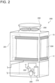
- Fig. 2 schematically illustrates the outdoor unit 200 according to Embodiment 1.
- the outdoor unit 200 according to Embodiment 1 is of top-flow type in which an air outlet 202 is provided at the top center of a housing 201, for the outdoor fan 250 to blow air upward through the air outlet 202.
- the outdoor heat exchanger 230 illustrated in Fig. 2 is only an upper part that is located in an upper area of the housing 201 as a matter of description, the outdoor heat exchanger 230 included in the outdoor unit 200 according to Embodiment 1 extends up to a position close to the bottom of the housing 201.
- the outdoor unit 200 includes the compressor 210, the flow switching device 220, the outdoor heat exchanger 230, and an accumulator 240, which are devices included in the refrigerant circuit 1.
- the compressor 210 is configured to suction a low-temperature low-pressure refrigerant, compress the suctioned refrigerant into a high-temperature high-pressure refrigerant, and discharge the refrigerant.
- the compressor 210 is, for example, an inverter compressor whose capacity is controllable by changing the operating frequency thereof.
- the capacity of the inverter compressor refers to the amount of refrigerant delivery per unit time.
- the flow switching device 220 is, for example, a four-way valve and is configured to switch directions for the refrigerant to flow, thereby switching the cooling operation and the heating operation therebetween.
- the flow switching device 220 may be, for example, any combination of two-way valves and three-way valves, instead of the four-way valve.
- the flow switching device 220 connects the discharge side of the compressor 210 to the indoor heat exchanger 110, and also connects the suction side of the compressor 210 to the outdoor heat exchanger 230.
- the flow switching device 220 connects the discharge side of the compressor 210 to the outdoor heat exchanger 230, and also connects the suction side of the compressor 210 to the indoor heat exchanger 110.
- the accumulator 240 is provided on the suction side of the compressor 210.
- the accumulator 240 allows a refrigerant in a gas state (hereinafter referred to as a gas refrigerant) to pass therethrough but stores a refrigerant in a liquid state (hereinafter referred to as a liquid refrigerant) therein.
- the outdoor heat exchanger 230 causes the refrigerant to exchange heat with outdoor air.
- the refrigerant is a fluid serving as a heat-exchange medium for the outdoor heat exchanger 230.
- the outdoor heat exchanger 230 serves as an evaporator and evaporates the refrigerant into gas.
- the outdoor heat exchanger 230 serves as a condenser and as a subcooler, and subcools the refrigerant by condensing the refrigerant into liquid.
- the outdoor fan 250 is provided above the outdoor heat exchanger 230. When activated, the outdoor fan 250 causes air outside the outdoor unit 200 to flow through the outdoor heat exchanger 230 and then blows the air upward through the air outlet 202.
- the solid-line arrows in Fig. 1 represent the flow of the refrigerant in the heating operation.
- the high-temperature high-pressure gas refrigerant obtained through the compression by the compressor 210 and discharged from the compressor 210 flows through the flow switching device 220 into the indoor heat exchanger 110. While the gas refrigerant is flowing through the indoor heat exchanger 110, the gas refrigerant exchanges heat with, for example, the air in the air-conditioning target space, thereby being condensed into liquid.
- the cooling operation is as follows.
- the broken-line arrows in Fig. 1 represent the flow of the refrigerant in the cooling operation.
- the high-temperature high-pressure gas refrigerant obtained through the compression by the compressor 210 and discharged from the compressor 210 flows through the flow switching device 220 into the outdoor heat exchanger 230.
- the gas refrigerant flowing through the outdoor heat exchanger 230 exchanges heat with the outdoor air supplied from the outdoor fan 250, thereby being condensed into liquid.
- the liquid refrigerant then flows through the expansion device 120. While the refrigerant is flowing through the expansion device 120, the refrigerant is decompressed.
- the refrigerant decompressed by the expansion device 120 takes a two-phase gas-liquid state and flows through the indoor heat exchanger 110.
- the refrigerant exchanges heat with, for example, the air in the air-conditioning target space, thereby being evaporated into gas.
- the gas refrigerant then flows through the flow switching device 220 and the accumulator 240 and is suctioned into the compressor 210 again.
- the refrigerant is thus made to circulate through the air-conditioning apparatus and is used for cooling-related air-conditioning.
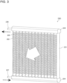
- Fig. 3 is a perspective view of an outdoor heat exchanger 230 according to Embodiment 1.
- the broken-line arrows in Fig. 3 represent the flow of the refrigerant in the cooling operation.
- the white arrow in Fig. 3 represents the flow of the air.
- the outdoor heat exchanger 230 according to Embodiment 1 includes a pair of headers, which are two distribution headers 234. The pair of headers are apart from each other at the upper and lower positions in the heightwise direction.
- the refrigerant is to flow through the insides of the flat tubes 232.
- the flat tubes 232 extend in the top-bottom direction and are arranged side by side at flat faces thereof in such a manner as to be parallel to one another.
- the flat tubes 232 are each a heat transfer tube having a flat cross-sectional shape. Outer faces of the tube that extend along the respective long sides of the flat cross section are flat, whereas the other outer faces of the tube that extend along the respective short sides of the flat cross section are curved.
- the long sides extend in the airflow direction. The short sides are orthogonal to the long sides.
- the flat tube 232 according to Embodiment 1 is a multi-port flat tube, which has thereinside a plurality of ports each serving as a passageway for the refrigerant.
- the ports of the flat tube 232 form passageways between the two distribution headers 234, and therefore extend in the heightwise direction.
- a fin 233 Between each two adjacent flat tubes 232 is provided a fin 233.
- the fin 233 has a wavy shape. The apexes of the fin 233 are joined to the flat faces of the flat tubes 232.
- the flat-tube group 231 is provided at two ends thereof with the respective distribution headers 234.
- the distribution headers 234 each receive the lower ends or upper ends of the flat tubes 232 forming the flat-tube group 231.
- One of the distribution headers 234 has at one end thereof a hot-gas-refrigerant inlet (not illustrated).
- the lower distribution header 234 has the hot-gas-refrigerant inlet at one end thereof.
- the hot-gas-refrigerant inlet is connected to the refrigerant circuit 1 of the air-conditioning apparatus through a gas pipe 237; for example, to the discharge side of the compressor 210 in the cooling operation. Therefore, the distribution header 234 that has the refrigerant inlet is also referred to as a gas header.
- the distribution header 234 having the refrigerant inlet allows, in the cooling operation, a high-temperature high-pressure gas refrigerant (hereinafter also referred to as a hot gas refrigerant) received from the compressor 210 to flow into the outdoor heat exchanger 230, and, in the heating operation, a low-temperature low-pressure gas refrigerant obtained through the heat exchange in the outdoor heat exchanger 230 to be discharged to the refrigerant circuit 1.
- the hot-gas-refrigerant inlet serves as a hot-gas-refrigerant-receiving part.
- the hot gas refrigerant is not limited to a single-phase gas refrigerant and may alternatively be a two-phase gas-liquid refrigerant with a gas-phase portion that is at 0 degrees C or above.
- the other distribution header 234 has at one end thereof a liquid-refrigerant outlet (not illustrated).
- the upper distribution header 234 has the liquid-refrigerant outlet at one end thereof.
- the liquid-refrigerant outlet is connected to the refrigerant circuit 1 of the air-conditioning apparatus through a liquid pipe 236. Therefore, the distribution header 234 that has the liquid-refrigerant outlet is also referred to as a liquid header.
- the distribution header 234 having the liquid-refrigerant outlet allows, in the heating operation, a low-temperature low-pressure two-phase refrigerant to flow into the outdoor heat exchanger 230, and, in the cooling operation, a low-temperature high-pressure liquid refrigerant obtained through the heat exchange in the outdoor heat exchanger 230 to be discharged.
- the liquid-refrigerant outlet serves as a liquid-refrigerant-discharging part.
- the plurality of flat tubes 232, the plurality of fins 233, and the distribution headers 234 are each made of aluminum and are joined together by brazing.
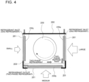
- Fig. 4 is a schematic plan view of the outdoor unit 200 according to Embodiment 1 and illustrates how refrigerant flows in the cooling operation.
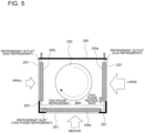
- Fig. 5 is a schematic plan view of the outdoor unit 200 according to Embodiment 1 and illustrates how refrigerant flows in the heating operation.
- Fig. 6 illustrates the temperature distribution in the heating operation, over outdoor heat exchangers 230 included in the outdoor unit 200 according to Embodiment 1.
- the housing 201 has a rectangular plan-view shape with four lateral faces. Three of the four lateral faces serve as permeable faces 261, through which air is permeable. The remaining one lateral face serves as a sealed face 260, through which air is nonpermeable.
- the permeable faces 261 are provided therealong with respective outdoor heat exchangers 230 (230a to 230c). That is, three outdoor heat exchangers 230 are provided inside the housing 201.
- refrigerant flows through the inside of the outdoor unit 200 as represented by the diagonally hatched arrows.
- the outdoor heat exchangers 230 arranged in the direction of rotation of the outdoor fan 250 are denoted in order as a first outdoor heat exchanger 230a, a second outdoor heat exchanger 230b, and a third outdoor heat exchanger 230c.
- the outdoor heat exchangers 230 are connected to one another by a refrigerant pipe 203 such that the first outdoor heat exchanger 230a and the third outdoor heat exchanger 230c are located on the upstream side in the flow of the refrigerant, and the second outdoor heat exchanger 230b is located on the downstream side in the flow of the refrigerant.
- refrigerant flows through the inside of the outdoor unit 200 as represented by the diagonally hatched arrows. Furthermore, the outdoor heat exchangers 230 are connected to one another by the refrigerant pipe 203 such that the first outdoor heat exchanger 230a and the third outdoor heat exchanger 230c are located on the downstream side in the flow of the refrigerant, and the second outdoor heat exchanger 230b is located on the upstream side in the flow of the refrigerant.
- the heat-exchanger performance varies with the variation in the wind-speed distribution.
- the variation causes uneven frosting on those outdoor heat exchangers that exhibit lower heat-exchanger performance. Consequently, the heating capacity is reduced.
- the first outdoor heat exchanger 230a through which wind flows at the highest speed, serves as the main heat exchanger that achieves a large amount of heat exchange with a large difference between the air temperature and the refrigerant temperature, yielding high heat-exchanger performance.
- Such a configuration suppresses the uneven frosting of the first outdoor heat exchanger 230a of the highest wind speed, and thus suppresses the reduction in the heating capacity under a low-temperature condition.
- Fig. 7 is a schematic plan view of a modification of the outdoor unit 200 according to Embodiment 1 and illustrates how refrigerant flows in the cooling operation.
- Fig. 8 is a schematic plan view of the modification of the outdoor unit 200 according to Embodiment 1 and illustrates how refrigerant flows in the heating operation.
- Embodiment 1 employs a single outdoor fan 250 that is provided at the top center of the housing 201
- the outdoor fan 250 is not limited thereto.
- Two or more outdoor fans 250 may be provided at the top center of the housing 201 as illustrated in Figs. 7 and 8 , as long as all of the outdoor fans 250 are configured to rotate in the same direction.
- the arrangement of the three outdoor heat exchangers 230 in the modification of Embodiment 1 that is illustrated in Figs. 7 and 8 is the same as in Embodiment 1 illustrated in Figs. 4 and 5 .
- the wind-speed distribution (the white arrows) varies among the permeable faces 261 of the housing 201.
- the wind speed is the highest (large) for the first outdoor heat exchanger 230a, the lowest (small) for the third outdoor heat exchanger 230c, and moderate (medium) for the second outdoor heat exchanger 230b between the two.
- the cooling operation is performed such that the flows of the refrigerant in the first outdoor heat exchanger 230a through which wind flows at the highest speed and in the third outdoor heat exchanger 230c through which wind flows at the lowest speed are parallel to each other and are collected together in the second outdoor heat exchanger 230c through which wind flows at the moderate speed.
- the first outdoor heat exchanger 230a and the third outdoor heat exchanger 230c serve as upstream heat exchangers
- the second outdoor heat exchanger 230c through which wind flows at the moderate speed serves as a downstream heat exchanger.
- the refrigerant takes a two-phase gas-liquid state when flowing through the outdoor heat exchanger 230 of the highest wind speed and the outdoor heat exchanger 230 of the lowest wind speed. Therefore, the subcooled-zone liquid is less likely to be generated. Furthermore, any subcooled-zone liquid is handled by the outdoor heat exchanger 230 of the moderate wind speed. Consequently, the heat-exchanger performance is less likely to be deteriorated because of the variation in the wind-speed distribution. In the heating operation, as illustrated in Figs.
- the first outdoor heat exchanger 230a of the highest wind speed serves as the main heat exchanger that achieves a large amount of heat exchange with a large difference between the air temperature and the refrigerant temperature, yielding high heat-exchanger performance.
- Such a configuration suppresses the uneven frosting of the first outdoor heat exchanger 230a of the highest wind speed, and thus suppresses the reduction in the heating capacity under a low-temperature condition.
- an outdoor unit 200 includes a housing 201 having a rectangular plan-view shape with an air outlet 202 provided at the top center, three outdoor heat exchangers 230 provided inside the housing 201, and an outdoor fan 250 provided above the three outdoor heat exchangers 230 and configured to blow air upward through the air outlet 202.
- the three outdoor heat exchangers 230 each include a flat-tube group 231 and a plurality of fins 233.
- the flat-tube group 231 includes a plurality of flat tubes 232 through the insides of which refrigerant is to flow.
- the flat tubes 232 extend in the top-bottom direction and are arranged side by side at the flat faces thereof in such a manner as to be parallel to one another.
- the fins 233 are each provided between corresponding two adjacent ones of the flat tubes 232 and are each joined to the flat faces of the corresponding two flat tubes 232.
- the housing 201 has four lateral faces. Three of the four lateral faces serve as permeable faces 261 through which air is permeable. The remaining one lateral face serves as a sealed face 260 through which air is nonpermeable.
- the three outdoor heat exchangers 230 extend along the respective permeable faces 261. With reference to the sealed face 260, the three outdoor heat exchangers 230 arranged in the direction of rotation of the outdoor fan 250 are denoted in order as a first outdoor heat exchanger 230a, a second outdoor heat exchanger 230b, and a third outdoor heat exchanger 230c.
- the three outdoor heat exchangers 230 are connected to one another such that, in the cooling operation, the first outdoor heat exchanger 230a and the third outdoor heat exchanger 230c are located on the upstream side in the flow of the refrigerant, and the second outdoor heat exchanger 230b is located on the downstream side in the flow of the refrigerant.
- the cooling operation is performed such that the flows of the refrigerant in the first outdoor heat exchanger 230a through which wind flows at the highest speed and in the third outdoor heat exchanger 230c through which wind flows at the lowest speed are parallel to each other and are collected together in the second outdoor heat exchanger 230b through which wind flows at a moderate speed.
- the first outdoor heat exchanger 230a and the third outdoor heat exchanger 230c serve as upstream heat exchangers
- the second outdoor heat exchanger 230b through which wind flows at the moderate speed serves as a downstream heat exchanger.
- the refrigerant takes a two-phase gas-liquid state when flowing through the outdoor heat exchanger 230 of the highest wind speed and the outdoor heat exchanger 230 of the lowest wind speed. Therefore, the subcooled-zone liquid is less likely to be generated. Furthermore, any subcooled-zone liquid is handled by the outdoor heat exchanger 230 of the moderate wind speed. Consequently, the heat-exchanger performance is less likely to be deteriorated because of the variation in the wind-speed distribution.
- Embodiment 2 will now be described. Any description that is redundant with Embodiment 1 is omitted, and any elements that are the same as or equivalent to those of Embodiment 1 are denoted by corresponding ones of the reference signs.
- Fig. 9 is a perspective view of an outdoor heat exchanger 230 according to Embodiment 2.
- the broken-line arrows in Fig. 9 represent the flow of the refrigerant in the cooling operation.
- the white arrow in Fig. 9 represents the flow of the air.
- the outdoor heat exchanger 230 according to Embodiment 2 includes a pair of headers, which are a set of two distribution headers 234 and a row-connecting header 238.
- the pair of headers are apart from each other at the upper and lower positions in the heightwise direction.
- the flat-tube groups 231 are provided between the set of two distribution headers 234 and the row-connecting header 238.
- the refrigerant is to flow through the insides of the flat tubes 232.
- the flat tubes 232 extend in the top-bottom direction and are arranged side by side at the flat faces thereof in such a manner as to be parallel to one another.
- the flat-tube groups 231 form two respective rows that are side by side in the airflow direction.
- the flat tubes 232 are each a heat transfer tube having a flat cross-sectional shape. Outer faces of the tube that extend along the respective long sides of the flat cross section are flat, whereas the other outer faces of the tube that extend along the respective short sides of the flat cross section are curved.
- the long sides extend in the airflow direction.
- the short sides are orthogonal to the long sides.
- the flat tubes 232 according to Embodiment 2 are each a multi-port flat tube, which has thereinside a plurality of ports each serving as a passageway for the refrigerant.
- the ports of the flat tube 232 form passageways between the set of distribution headers 234 and the row-connecting header 238, and therefore extend in the heightwise direction.
- a fin 233 Between each two adjacent flat tubes 232 is provided a fin 233.
- the fin 233 has a wavy shape. The apexes of the fin 233 are joined to the flat faces of the flat tubes 232.
- One of the distribution headers 234 that is on the downstream side (hereinafter referred to as the leeward side) in the airflow direction has at one end thereof a hot-gas-refrigerant inlet (not illustrated).
- the hot-gas-refrigerant inlet is connected to the refrigerant circuit 1 of the air-conditioning apparatus through a gas pipe 237. Therefore, the leeward one of the distribution headers 234 that has the hot-gas-refrigerant inlet is also referred to as a gas header.
- the plurality of flat tubes 232, the plurality of fins 233, the distribution headers 234, and the row-connecting header 238 are each made of aluminum and are joined together by brazing.
- Fig. 10 is a schematic plan view of an outdoor unit 200 according to Embodiment 2 and illustrates how refrigerant flows in the cooling operation.
- the housing 201 has a rectangular plan-view shape with four lateral faces. Three of the four lateral faces serve as permeable faces 261, through which air is permeable. The remaining one lateral face serves as a sealed face 260, through which air is nonpermeable.
- the permeable faces 261 are provided with respective outdoor heat exchangers 230 (230a to 230c). That is, three outdoor heat exchangers 230 are provided in the housing 201.
- refrigerant flows through the inside of the outdoor unit 200 as represented by the diagonally hatched arrows.
- the outdoor heat exchangers 230 arranged in the direction of rotation of each outdoor fan 250 are denoted in order as a first outdoor heat exchanger 230a, a second outdoor heat exchanger 230b, and a third outdoor heat exchanger 230c.
- the outdoor heat exchangers 230 are connected to one another by a refrigerant pipe 203 such that the first outdoor heat exchanger 230a and the third outdoor heat exchanger 230c are located on the upstream side in the flow of the refrigerant, and the second outdoor heat exchanger 230b is located on the downstream side in the flow of the refrigerant.
- Each of the outdoor heat exchangers 230 is oriented such that the gas refrigerant (black solid-line arrow) in the cooling operation acts as a counterflow to the airflow (white arrow).
- Fig. 11 illustrates the temperature difference between air and refrigerant over relevant zones in the cooling operation of the outdoor heat exchangers 230 according to Embodiment 2.
- the gas refrigerant black solid-line arrow
- the airflow white arrow
- the layered width of the flat tubes 232 included in the outdoor heat exchangers 230 may be increased, whereby the heat-exchanger performance may be increased.
- an outdoor unit 200 includes three outdoor heat exchangers 230 each of which includes flat-tube groups 231 forming two respective rows that are side by side in the airflow direction.
- the three outdoor heat exchangers 230 each further include two distribution headers 234 and a row-connecting header 238.
- the two distribution headers 234 are located in the same direction in the heightwise direction and each receive one end of a corresponding one of the flat-tube groups 231.
- the row-connecting header 238 receives the other ends of the two flat-tube groups 231.
- One of the distribution headers 234 that receives one end of the leeward one of the flat-tube groups 231 has a refrigerant inlet provided such that the gas refrigerant in the cooling operation acts as a counterflow to the airflow.
- the gas refrigerant in the cooling operation acts as a counterflow to the airflow. Therefore, a large temperature difference between air and refrigerant is produced over all of the zones for the outdoor heat exchangers 230. Thus, the heat-exchanger performance is increased. Furthermore, since the liquid pipe 236 serving as a liquid-refrigerant outlet is not necessary at a portion facing the sealed face 260, the layered width of the flat tubes 232 included in the outdoor heat exchangers 230 may be increased, whereby the heat-exchanger performance may be increased.
- Embodiment 3 will now be described. Any description that is redundant with Embodiment 1 or 2 is omitted, and any elements that are the same as or equivalent to those of Embodiment 1 or 2 are denoted by corresponding ones of the reference signs.
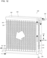
- Fig. 12 is a perspective view of an outdoor heat exchanger 230 according to Embodiment 3.
- the broken-line arrows in Fig. 12 represent the flow of the refrigerant in the cooling operation.
- the white arrow in Fig. 12 represents the flow of the air.
- the outdoor heat exchanger 230 according to Embodiment 3 includes pairs of headers. Each pair includes two distribution headers 234. The two headers are apart from each other at the upper and lower positions in the heightwise direction. The pairs of headers are arranged in two rows that are side by side in the airflow direction.
- a 231 which includes a plurality of flat tubes 232.
- the refrigerant is to flow through the insides of the flat tubes 232.
- the flat tubes 232 extend in the top-bottom direction and are arranged side by side at the flat faces thereof in such a manner as to be parallel to one another.
- the flat-tube groups 231 form two respective rows that are side by side in the airflow direction.
- the flat tubes 232 are each a heat transfer tube having a flat cross-sectional shape. Outer faces of the tube that extend along the respective long sides of the flat cross section are flat, whereas the other outer faces of the tube that extend along the respective short sides of the flat cross section are curved. The long sides extend in the airflow direction.
- the short sides are orthogonal to the long sides.
- the flat tube 232 according to Embodiment 1 is a multi-port flat tube, which has thereinside a plurality of ports each serving as a passageway for the refrigerant.
- the ports of the flat tube 232 form passageways between the pair of distribution headers 234, and therefore extend in the heightwise direction.
- Between each two adjacent flat tubes 232 is provided a fin 233.
- the fin 233 has a wavy shape. The apexes of the fin 233 are joined to the flat faces of the flat tubes 232.
- the flat-tube groups 231 are each provided at two ends thereof with corresponding ones of the distribution headers 234.
- the distribution headers 234 each receive the lower ends or upper ends of the flat tubes 232 forming the corresponding flat-tube group 231.
- One of the leeward distribution headers 234 has at one end thereof a hot-gas-refrigerant inlet (not illustrated).
- the lower one of the leeward distribution headers 234 has the hot-gas-refrigerant inlet at one end thereof.
- the hot-gas-refrigerant inlet is connected to the refrigerant circuit 1 of the air-conditioning apparatus through a gas pipe 237. Therefore, the one of the leeward distribution headers 234 that has the refrigerant inlet is also referred to as a gas header.
- the one of the leeward distribution headers 234 that has the refrigerant inlet allows, in the cooling operation, a high-temperature high-pressure gas refrigerant received from the compressor 210 to flow into the outdoor heat exchanger 230, and, in the heating operation, a low-temperature low-pressure gas refrigerant obtained through the heat exchange in the outdoor heat exchanger 230 to be discharged to the refrigerant circuit 1.
- the hot-gas-refrigerant inlet serves as a hot-gas-refrigerant-receiving part.
- the hot gas refrigerant is not limited to a single-phase gas refrigerant and may alternatively be a two-phase gas-liquid refrigerant with a gas-phase portion that is at 0 degrees C or above.
- the other one of the leeward distribution headers 234 is connected at one end thereof to one end of one of the windward distribution headers 234 by an inter-row connection pipe 239.
- the other one of the leeward distribution headers 234 and the one of the windward distribution headers 234 are located in the same direction in the heightwise direction.
- the other one of the leeward distribution headers 234 and the one of the windward distribution headers 234 are both located on the upper side.
- the inter-row connection pipe 239 allows the refrigerant in the other one of the leeward distribution headers 234 to flow into the one of the windward distribution headers 234.
- the other one of the windward distribution headers 234 has at one end thereof a liquid-refrigerant outlet (not illustrated).
- the lower one of the windward distribution headers 234 has a liquid-refrigerant outlet at one end thereof.
- the liquid-refrigerant outlet is connected to the refrigerant circuit 1 of the air-conditioning apparatus through a liquid pipe 236. Therefore, the other one of the windward distribution headers 234 is also referred to as a liquid header.
- the other one of the windward distribution headers 234 allows, in the heating operation, a low-temperature low-pressure two-phase refrigerant to flow into the outdoor heat exchanger 230, and, in the cooling operation, a low-temperature high-pressure liquid refrigerant obtained through the heat exchange in the outdoor heat exchanger 230 to be discharged.
- the liquid-refrigerant outlet serves as a liquid-refrigerant-discharging part.
- the one of the leeward distribution headers 234 and the other of the windward distribution headers 234 are located in the same direction in the heightwise direction. In Embodiment 3, as illustrated in Fig. 12 , the one of the leeward distribution headers 234 and the other of the windward distribution headers 234 are both located on the lower side.
- the plurality of flat tubes 232, the plurality of fins 233, and the distribution headers 234 are each made of aluminum and are joined together by brazing.
- Fig. 13 is a schematic plan view of an outdoor unit 200 according to Embodiment 3 and illustrates how refrigerant flows in the cooling operation.
- the housing 201 has a rectangular plan-view shape with four lateral faces. Three of the four lateral faces serve as permeable faces 261, through which air is permeable. The remaining one lateral face serves as a sealed face 260, through which air is nonpermeable.
- the permeable faces 261 are provided with respective outdoor heat exchangers 230 (230a to 230c). That is, three outdoor heat exchangers 230 are provided in the housing 201.
- refrigerant flows through the inside of the outdoor unit 200 as represented by the diagonally hatched arrows.
- the outdoor heat exchangers 230 arranged in the direction of rotation of each outdoor fan 250 are denoted in order as a first outdoor heat exchanger 230a, a second outdoor heat exchanger 230b, and a third outdoor heat exchanger 230c.
- the outdoor heat exchangers 230 are connected to one another by a refrigerant pipe 203 such that the first outdoor heat exchanger 230a and the third outdoor heat exchanger 230c are located on the upstream side in the flow of the refrigerant, and the second outdoor heat exchanger 230b is located on the downstream side in the flow of the refrigerant.
- Each of the outdoor heat exchangers 230 is oriented such that the gas refrigerant (black solid-line arrow) in the cooling operation acts as a counterflow to the airflow (white arrow).
- Embodiment 3 since the outdoor heat exchangers 230 are configured as above, the gas refrigerant (black solid-line arrow) in the cooling operation acts as a counterflow to the airflow (white arrow). Therefore, as illustrated in Fig. 11 , a large temperature difference between air and refrigerant is produced over all of the zones for the outdoor heat exchangers 230. Thus, the heat-exchanger performance is increased. Furthermore, since the liquid pipe 236 serving as a liquid-refrigerant outlet is not necessary at a portion facing the sealed face 260, the layered width of the flat tubes 232 included in the outdoor heat exchangers 230 may be increased, whereby the heat-exchanger performance may be increased.
- an outdoor unit 200 includes three outdoor heat exchangers 230 each of which includes flat-tube groups 231 forming two respective rows that are side by side in the airflow direction.
- the three outdoor heat exchangers 230 each further include four distribution headers 234 that receive both ends of the flat-tube groups 231.
- One of the distribution headers 234 that receives one end of a leeward one of the flat-tube groups 231 has a refrigerant inlet provided such that the gas refrigerant in the cooling operation acts as a counterflow to the airflow.
- Another one of the distribution headers 234 that receives the other end of the leeward flat-tube group 231 and yet another one of the distribution headers 234 that is located in the same direction in the heightwise direction as the another distribution header 234 and that receives one end of a windward one of the flat-tube groups 231 are connected to each other by an inter-row connection pipe 239.
- the gas refrigerant in the cooling operation acts as a counterflow to the airflow. Therefore, a large temperature difference between air and refrigerant is produced over all of the zones for the outdoor heat exchangers 230. Thus, the heat-exchanger performance is increased. Furthermore, since the liquid pipe 236 serving as a liquid-refrigerant outlet is not necessary at a portion facing the sealed face 260, the layered width of the flat tubes 232 included in the outdoor heat exchangers 230 may be increased, whereby the heat-exchanger performance may be increased.
- Embodiment 4 will now be described. Any description that is redundant with any of Embodiments 1 to 3 is omitted, and any elements that are the same as or equivalent to those of any of Embodiments 1 to 3 are denoted by corresponding ones of the reference signs.
- the surface area of the fins 233 included in the third outdoor heat exchanger 230c through which wind flows at the lowest speed is smaller than the surface area of the fins 233 included in the first outdoor heat exchanger 230a through which wind flows at the highest speed.
- the fin pitch or flat-tube pitch, for example, of the third outdoor heat exchanger 230c is greater than that of the first outdoor heat exchanger 230a.
- the width, in the row direction, of each of the flat-tube groups 231 in the third outdoor heat exchanger 230c is smaller than the width, in the row direction, of each of the flat-tube groups 231 in the first outdoor heat exchanger 230a, or the number of rows in the third outdoor heat exchanger 230c is smaller than the number of rows in the first outdoor heat exchanger 230a.
- the airflow resistance becomes smaller for the third outdoor heat exchanger 230c than for the first outdoor heat exchanger 230a, allowing wind to flow through the third outdoor heat exchanger 230c more easily.
- the airflow resistances of the outdoor heat exchangers 230 are adjusted to reduce the variation in the heat-exchanger performance among the outdoor heat exchangers 230. Therefore, the heat-exchanger performance is less likely to be deteriorated because of the variation in the wind-speed distribution.
- the airflow resistance of the third outdoor heat exchanger 230c is smaller than the airflow resistance of the first outdoor heat exchanger 230a.
- the airflow resistances of the outdoor heat exchangers 230 are adjusted to reduce the variation in the heat-exchanger performance among the outdoor heat exchangers 230. Therefore, the heat-exchanger performance is less likely to be deteriorated because of the variation in the wind-speed distribution.
- Embodiment 5 will now be described. Any description that is redundant with any of Embodiments 1 to 4 is omitted, and any elements that are the same as or equivalent to those of any of Embodiments 1 to 4 are denoted by corresponding ones of the reference signs.
- Fig. 14 is a schematic plan view of an outdoor unit 200 according to Embodiment 5 and illustrates how refrigerant flows in the cooling operation.
- the housing 201 has a rectangular plan-view shape with four lateral faces. Three of the four lateral faces serve as permeable faces 261, through which air is permeable. The remaining one lateral face serves as a sealed face 260, through which air is nonpermeable.
- the permeable faces 261 are provided with respective outdoor heat exchangers 230 (230a to 230c). That is, three outdoor heat exchangers 230 are provided in the housing 201.
- refrigerant flows through the inside of the outdoor unit 200 as represented by the diagonally hatched arrows.
- the outdoor heat exchangers 230 arranged in the direction of rotation of each outdoor fan 250 are denoted in order as a first outdoor heat exchanger 230a, a second outdoor heat exchanger 230b, and a third outdoor heat exchanger 230c.
- the outdoor heat exchangers 230 are connected to one another by a refrigerant pipe 203 such that the first outdoor heat exchanger 230a and the third outdoor heat exchanger 230c are located on the upstream side in the flow of the refrigerant, and the second outdoor heat exchanger 230b is located on the downstream side in the flow of the refrigerant.
- Each of the outdoor heat exchangers 230 is oriented such that the gas refrigerant (black solid-line arrow) in the cooling operation acts as a counterflow to the airflow (white arrow).
- a part of the refrigerant pipe 203 that connects the first outdoor heat exchanger 230a and the third outdoor heat exchanger 230c to each other is provided with an expansion device 280.
- the refrigerant pipe 203 is configured such that the flow resistance, R23, between the second outdoor heat exchanger 230b and the third outdoor heat exchanger 230c becomes greater than the flow resistance, R21, between the second outdoor heat exchanger 230b and the first outdoor heat exchanger 230a (R23 > R21).
- the way of increasing the flow resistance by using the refrigerant pipe 203 may be as follows, for example: the diameter of the refrigerant pipe 203 may be reduced, the number of bend portions in the refrigerant pipe 203 may be increased, or the Cv value of the expansion device 280 may be reduced.
- the expansion device 280 may be, for example, an electronic expansion valve, and the Cv value of the electronic expansion valve may be adjusted. In such a configuration, a larger amount of refrigerant flows through an area where wind flows at a higher speed, whereas a smaller amount of refrigerant flows through an area where wind flows at a lower speed.
- making the flow resistance R23 greater than the flow resistance R21 enables the supply of the refrigerant to the outdoor heat exchangers 230 at respective flow rates that match the wind-speed distribution, and reduces the variation in the heat-exchanger performance among the outdoor heat exchangers 230. Therefore, the heat-exchanger performance is less likely to be deteriorated because of the variation in the wind-speed distribution.
- refrigerant circuit 100: indoor unit, 110: indoor heat exchanger, 120: expansion device, 130: indoor fan, 200: outdoor unit, 201: housing, 202: air outlet, 203: refrigerant pipe, 210: compressor, 220: flow switching device, 230: outdoor heat exchanger, 230a: outdoor heat exchanger, 230b: outdoor heat exchanger, 230c: outdoor heat exchanger, 231: flat-tube group, 232: flat tube, 233: fin, 234: distribution header, 236: liquid pipe, 237: gas pipe, 238: row-connecting header, 239: inter-row connection pipe, 240: accumulator, 250: outdoor fan, 260: sealed face, 261: permeable face, 280: expansion device, 300: refrigerant pipe
Landscapes
- Engineering & Computer Science (AREA)
- Mechanical Engineering (AREA)
- General Engineering & Computer Science (AREA)
- Chemical & Material Sciences (AREA)
- Combustion & Propulsion (AREA)
- Physics & Mathematics (AREA)
- Thermal Sciences (AREA)
- Other Air-Conditioning Systems (AREA)
Abstract
Description
- The present disclosure relates to a top-flow outdoor unit and an air-conditioning apparatus including the same.
- A known art provides a top-flow outdoor unit (see
Patent Literature 1, for example) including in a housing thereof outdoor heat exchangers and an outdoor fan. The outdoor heat exchangers each include a plurality of flat tubes, a plurality of fins, and headers. The flat tubes extend in the vertical direction and are arranged at intervals in the horizontal direction. The fins each connect between adjacent ones of the flat tubes and transfer heat to the flat tubes. The headers are provided at the upper end and lower end of the plurality of flat tubes. The outdoor fan is configured to blow air upward. - In the top-flow outdoor unit, the outdoor heat exchangers are arranged along the periphery of the housing, and the outdoor fan is located above the outdoor heat exchangers and at the top of the housing.
- Patent Literature 1:
Japanese Patent No. 6595125 - According to
Patent Literature 1, the wind-speed distribution varies in the peripheral direction of the housing. That is, the speed of the wind flowing through the heat exchangers varies, resulting in an uneven distribution of heat load. Therefore, those outdoor heat exchangers through which wind flows at high speeds achieve a large amount of heat exchange, with an increased subcooled-zone liquid. With a subcooled-zone liquid, the temperature difference between refrigerant and air is small. Therefore, the subcooled-zone liquid is less contributing in the outdoor heat exchanger. On the other hand, those outdoor heat exchangers through which wind flows at low speeds achieve a small amount of heat exchange, with a reduced subcooled-zone liquid. To achieve a desired amount of heat exchange by using such outdoor heat exchangers among which the amount of heat exchange varies, an increased pressure is unnecessarily applied to those outdoor heat exchangers through which wind flows at high speeds and that do not require pressure increase. Therefore, the loss of energy increases. Consequently, the heat-exchanger performance of the outdoor heat exchangers as a whole is deteriorated. - The present disclosure is to solve the above problem, and an object of the present disclosure is to provide an outdoor unit and an air-conditioning apparatus including the same, in which the performance of heat exchange is less likely to be deteriorated because of the variation in the wind-speed distribution.
- An outdoor unit according to an embodiment of the present disclosure includes a housing having a rectangular plan-view shape with an air outlet provided at a top center; three outdoor heat exchangers provided inside the housing; and an outdoor fan provided above the three outdoor heat exchangers and configured to blow air upward through the air outlet. The three outdoor heat exchangers each include a flat-tube group including a plurality of flat tubes through insides of which refrigerant is to flow, the flat tubes extending in a top-bottom direction and arranged side by side at flat faces of the flat tubes in such a manner as to be parallel to one another. The housing has four lateral faces, three of the four lateral faces serving as permeable faces through which air is permeable, a remaining one of the four lateral faces serving as a sealed face through which air is nonpermeable. The three outdoor heat exchangers extend along the respective permeable faces. With reference to the sealed face, letting the three outdoor heat exchangers arranged in a direction of rotation of the outdoor fan be denoted in order as a first outdoor heat exchanger; a second outdoor heat exchanger; and a third outdoor heat exchanger, the three outdoor heat exchangers are connected to one another such that, in a cooling operation, the first outdoor heat exchanger and the third outdoor heat exchanger are located on an upstream side in a flow of the refrigerant, and the second outdoor heat exchanger is located on a downstream side in the flow of the refrigerant.
- An air-conditioning apparatus according to another embodiment of the present disclosure includes the above outdoor unit and an indoor unit.
- In the outdoor unit according to each of the above embodiments of the present disclosure, the cooling operation is performed such that the flows of the refrigerant in the first outdoor heat exchanger through which wind flows at the highest speed and in the third outdoor heat exchanger through which wind flows at the lowest speed are parallel to each other and are collected together in the second outdoor heat exchanger through which wind flows at a moderate speed. Thus, the first outdoor heat exchanger and the third outdoor heat exchanger serve as upstream heat exchangers, and the second outdoor heat exchanger through which wind flows at the moderate speed serves as a downstream heat exchanger. In such a configuration, the refrigerant takes a two-phase gas-liquid state when flowing through the outdoor heat exchanger of the highest wind speed and the outdoor heat exchanger of the lowest wind speed. Therefore, the subcooled-zone liquid is less likely to be generated. Furthermore, any subcooled-zone liquid is handled by the outdoor heat exchanger of the moderate wind speed. Consequently, the heat-exchanger performance is less likely to be deteriorated because of the variation in the wind-speed distribution.
-
- [
Fig. 1] Fig. 1 illustrates an air-conditioning apparatus including an outdoor unit according to Embodiment 1. - [
Fig. 2] Fig. 2 schematically illustrates the outdoor unit according toEmbodiment 1. - [
Fig. 3] Fig. 3 is a perspective view of an outdoor heat exchanger according to Embodiment 1. - [
Fig. 4] Fig. 4 is a schematic plan view of the outdoor unit according toEmbodiment 1 and illustrates how refrigerant flows in a cooling operation. - [
Fig. 5] Fig. 5 is a schematic plan view of the outdoor unit according toEmbodiment 1 and illustrates how refrigerant flows in a heating operation. - [
Fig. 6] Fig. 6 illustrates the temperature distribution in the heating operation, over outdoor heat exchangers included in the outdoor unit according to Embodiment 1. - [
Fig. 7] Fig. 7 is a schematic plan view of a modification of the outdoor unit according to Embodiment 1 and illustrates how refrigerant flows in the cooling operation. - [
Fig. 8] Fig. 8 is a schematic plan view of the modification of the outdoor unit according toEmbodiment 1 and illustrates how refrigerant flows in the heating operation. - [
Fig. 9] Fig. 9 is a perspective view of an outdoor heat exchanger according to Embodiment 2. - [
Fig. 10] Fig. 10 is a schematic plan view of an outdoor unit according to Embodiment 2 and illustrates how refrigerant flows in the cooling operation. - [
Fig. 11] Fig. 11 illustrates the temperature difference between air and refrigerant over relevant zones in the cooling operation of outdoor heat exchangers according to Embodiment 2. - [
Fig. 12] Fig. 12 is a perspective view of an outdoor heat exchanger according to Embodiment 3. - [
Fig. 13] Fig. 13 is a schematic plan view of an outdoor unit according toEmbodiment 3 and illustrates how refrigerant flows in the cooling operation. - [
Fig. 14] Fig. 14 is a schematic plan view of an outdoor unit according to Embodiment 5 and illustrates how refrigerant flows in the cooling operation. Description of Embodiments - Embodiments of the present disclosure will now be described with reference to the drawings. Note that the following embodiments do not limit the present disclosure. The elements illustrated in the drawings to be referred to below may be not to scale.
-
Fig. 1 illustrates an air-conditioning apparatus including anoutdoor unit 200 according to Embodiment 1. As illustrated inFig. 1 , the air-conditioning apparatus according to Embodiment 1 includes theoutdoor unit 200 and anindoor unit 100, which are connected to each other by arefrigerant pipe 300. Theoutdoor unit 200 includes acompressor 210, aflow switching device 220, and anoutdoor heat exchanger 230. Theindoor unit 100 includes anindoor heat exchanger 110 and anexpansion device 120. Thecompressor 210, theflow switching device 220, theoutdoor heat exchanger 230, theexpansion device 120, and theindoor heat exchanger 110 are connected to one another by therefrigerant pipe 300, whereby arefrigerant circuit 1 is formed for refrigerant to circulate therethrough. While the air-conditioning apparatus according to Embodiment 1 includes a singleoutdoor unit 200 and a singleindoor unit 100 that are connected to each other by therefrigerant pipe 300, the numbers ofoutdoor units 200 andindoor units 100 are not limited thereto. - The
indoor unit 100 including theindoor heat exchanger 110 and theexpansion device 120 further includes anindoor fan 130. Theexpansion device 120 is configured to decompress the refrigerant and thus expand the refrigerant. Theexpansion device 120 is, for example, an electronic expansion valve whose opening degree is adjustable. The opening degree of theexpansion device 120 is adjusted to control, in a cooling operation, the pressure of the refrigerant flowing into theindoor heat exchanger 110 and, in a heating operation, the pressure of the refrigerant flowing into theoutdoor heat exchanger 230. Theindoor heat exchanger 110 is configured to cause the refrigerant to exchange heat with indoor air, which is the air in an air-conditioning target space. Specifically, in the heating operation, theindoor heat exchanger 110 serves as a condenser and condenses the refrigerant into liquid. In the cooling operation, theindoor heat exchanger 110 serves as an evaporator and evaporates the refrigerant into gas. Theindoor fan 130 is configured to cause the indoor air to flow through theindoor heat exchanger 110 and thus supplies the indoor space with the air having flowed through theindoor heat exchanger 110. -
Fig. 2 schematically illustrates theoutdoor unit 200 according toEmbodiment 1. Theoutdoor unit 200 according toEmbodiment 1 is of top-flow type in which anair outlet 202 is provided at the top center of ahousing 201, for theoutdoor fan 250 to blow air upward through theair outlet 202. While theoutdoor heat exchanger 230 illustrated inFig. 2 is only an upper part that is located in an upper area of thehousing 201 as a matter of description, theoutdoor heat exchanger 230 included in theoutdoor unit 200 according toEmbodiment 1 extends up to a position close to the bottom of thehousing 201. - The
outdoor unit 200 includes thecompressor 210, theflow switching device 220, theoutdoor heat exchanger 230, and anaccumulator 240, which are devices included in therefrigerant circuit 1. Thecompressor 210 is configured to suction a low-temperature low-pressure refrigerant, compress the suctioned refrigerant into a high-temperature high-pressure refrigerant, and discharge the refrigerant. Thecompressor 210 is, for example, an inverter compressor whose capacity is controllable by changing the operating frequency thereof. The capacity of the inverter compressor refers to the amount of refrigerant delivery per unit time. - The
flow switching device 220 is, for example, a four-way valve and is configured to switch directions for the refrigerant to flow, thereby switching the cooling operation and the heating operation therebetween. Theflow switching device 220 may be, for example, any combination of two-way valves and three-way valves, instead of the four-way valve. For the heating operation, theflow switching device 220 connects the discharge side of thecompressor 210 to theindoor heat exchanger 110, and also connects the suction side of thecompressor 210 to theoutdoor heat exchanger 230. For the cooling operation, theflow switching device 220 connects the discharge side of thecompressor 210 to theoutdoor heat exchanger 230, and also connects the suction side of thecompressor 210 to theindoor heat exchanger 110. Theaccumulator 240 is provided on the suction side of thecompressor 210. Theaccumulator 240 allows a refrigerant in a gas state (hereinafter referred to as a gas refrigerant) to pass therethrough but stores a refrigerant in a liquid state (hereinafter referred to as a liquid refrigerant) therein. - The
outdoor heat exchanger 230 causes the refrigerant to exchange heat with outdoor air. The refrigerant is a fluid serving as a heat-exchange medium for theoutdoor heat exchanger 230. In the heating operation, theoutdoor heat exchanger 230 serves as an evaporator and evaporates the refrigerant into gas. In the cooling operation, theoutdoor heat exchanger 230 serves as a condenser and as a subcooler, and subcools the refrigerant by condensing the refrigerant into liquid. Theoutdoor fan 250 is provided above theoutdoor heat exchanger 230. When activated, theoutdoor fan 250 causes air outside theoutdoor unit 200 to flow through theoutdoor heat exchanger 230 and then blows the air upward through theair outlet 202. - Now, how the above devices included in the air-conditioning apparatus operate will be described, focusing on the flow of the refrigerant. First, how the devices included in the
refrigerant circuit 1 operate in the heating operation will be described, focusing on the flow of the refrigerant. The solid-line arrows inFig. 1 represent the flow of the refrigerant in the heating operation. The high-temperature high-pressure gas refrigerant obtained through the compression by thecompressor 210 and discharged from thecompressor 210 flows through theflow switching device 220 into theindoor heat exchanger 110. While the gas refrigerant is flowing through theindoor heat exchanger 110, the gas refrigerant exchanges heat with, for example, the air in the air-conditioning target space, thereby being condensed into liquid. The refrigerant thus condensed into liquid flows through theexpansion device 120. While the refrigerant is flowing through theexpansion device 120, the refrigerant is decompressed. The refrigerant decompressed by theexpansion device 120 takes a two-phase gas-liquid state and flows through theoutdoor heat exchanger 230. In theoutdoor heat exchanger 230, the refrigerant exchanges heat with the outdoor air supplied from theoutdoor fan 250, thereby being evaporated into gas. The gas refrigerant then flows through theflow switching device 220 and theaccumulator 240 and is suctioned into thecompressor 210 again. The refrigerant is thus made to circulate through the air-conditioning apparatus and is used for heating-related air-conditioning. - The cooling operation is as follows. The broken-line arrows in
Fig. 1 represent the flow of the refrigerant in the cooling operation. The high-temperature high-pressure gas refrigerant obtained through the compression by thecompressor 210 and discharged from thecompressor 210 flows through theflow switching device 220 into theoutdoor heat exchanger 230. The gas refrigerant flowing through theoutdoor heat exchanger 230 exchanges heat with the outdoor air supplied from theoutdoor fan 250, thereby being condensed into liquid. The liquid refrigerant then flows through theexpansion device 120. While the refrigerant is flowing through theexpansion device 120, the refrigerant is decompressed. The refrigerant decompressed by theexpansion device 120 takes a two-phase gas-liquid state and flows through theindoor heat exchanger 110. In theindoor heat exchanger 110, the refrigerant exchanges heat with, for example, the air in the air-conditioning target space, thereby being evaporated into gas. The gas refrigerant then flows through theflow switching device 220 and theaccumulator 240 and is suctioned into thecompressor 210 again. The refrigerant is thus made to circulate through the air-conditioning apparatus and is used for cooling-related air-conditioning. -
Fig. 3 is a perspective view of anoutdoor heat exchanger 230 according toEmbodiment 1. The broken-line arrows inFig. 3 represent the flow of the refrigerant in the cooling operation. The white arrow inFig. 3 represents the flow of the air. As illustrated inFig. 3 , theoutdoor heat exchanger 230 according toEmbodiment 1 includes a pair of headers, which are twodistribution headers 234. The pair of headers are apart from each other at the upper and lower positions in the heightwise direction. - Between the two
distribution headers 234 is provided a group of flat tubes 232 (hereinafter referred to as a flat-tube group 231). The refrigerant is to flow through the insides of theflat tubes 232. Theflat tubes 232 extend in the top-bottom direction and are arranged side by side at flat faces thereof in such a manner as to be parallel to one another. Theflat tubes 232 are each a heat transfer tube having a flat cross-sectional shape. Outer faces of the tube that extend along the respective long sides of the flat cross section are flat, whereas the other outer faces of the tube that extend along the respective short sides of the flat cross section are curved. The long sides extend in the airflow direction. The short sides are orthogonal to the long sides. Theflat tube 232 according toEmbodiment 1 is a multi-port flat tube, which has thereinside a plurality of ports each serving as a passageway for the refrigerant. InEmbodiment 1, the ports of theflat tube 232 form passageways between the twodistribution headers 234, and therefore extend in the heightwise direction. Between each two adjacentflat tubes 232 is provided afin 233. Thefin 233 has a wavy shape. The apexes of thefin 233 are joined to the flat faces of theflat tubes 232. - The flat-
tube group 231 is provided at two ends thereof with therespective distribution headers 234. Thedistribution headers 234 each receive the lower ends or upper ends of theflat tubes 232 forming the flat-tube group 231. - One of the
distribution headers 234 has at one end thereof a hot-gas-refrigerant inlet (not illustrated). InEmbodiment 1, referring toFig. 3 , thelower distribution header 234 has the hot-gas-refrigerant inlet at one end thereof. The hot-gas-refrigerant inlet is connected to therefrigerant circuit 1 of the air-conditioning apparatus through agas pipe 237; for example, to the discharge side of thecompressor 210 in the cooling operation. Therefore, thedistribution header 234 that has the refrigerant inlet is also referred to as a gas header. Thedistribution header 234 having the refrigerant inlet allows, in the cooling operation, a high-temperature high-pressure gas refrigerant (hereinafter also referred to as a hot gas refrigerant) received from thecompressor 210 to flow into theoutdoor heat exchanger 230, and, in the heating operation, a low-temperature low-pressure gas refrigerant obtained through the heat exchange in theoutdoor heat exchanger 230 to be discharged to therefrigerant circuit 1. In short, the hot-gas-refrigerant inlet serves as a hot-gas-refrigerant-receiving part. Note that the hot gas refrigerant is not limited to a single-phase gas refrigerant and may alternatively be a two-phase gas-liquid refrigerant with a gas-phase portion that is at 0 degrees C or above. - The
other distribution header 234 has at one end thereof a liquid-refrigerant outlet (not illustrated). InEmbodiment 1, referring toFig. 3 , theupper distribution header 234 has the liquid-refrigerant outlet at one end thereof. The liquid-refrigerant outlet is connected to therefrigerant circuit 1 of the air-conditioning apparatus through aliquid pipe 236. Therefore, thedistribution header 234 that has the liquid-refrigerant outlet is also referred to as a liquid header. Thedistribution header 234 having the liquid-refrigerant outlet allows, in the heating operation, a low-temperature low-pressure two-phase refrigerant to flow into theoutdoor heat exchanger 230, and, in the cooling operation, a low-temperature high-pressure liquid refrigerant obtained through the heat exchange in theoutdoor heat exchanger 230 to be discharged. In short, the liquid-refrigerant outlet serves as a liquid-refrigerant-discharging part. - The plurality of
flat tubes 232, the plurality offins 233, and thedistribution headers 234 are each made of aluminum and are joined together by brazing. -
Fig. 4 is a schematic plan view of theoutdoor unit 200 according toEmbodiment 1 and illustrates how refrigerant flows in the cooling operation.Fig. 5 is a schematic plan view of theoutdoor unit 200 according toEmbodiment 1 and illustrates how refrigerant flows in the heating operation.Fig. 6 illustrates the temperature distribution in the heating operation, overoutdoor heat exchangers 230 included in theoutdoor unit 200 according toEmbodiment 1. - As illustrated in
Figs. 4 and5 , thehousing 201 has a rectangular plan-view shape with four lateral faces. Three of the four lateral faces serve aspermeable faces 261, through which air is permeable. The remaining one lateral face serves as a sealedface 260, through which air is nonpermeable. The permeable faces 261 are provided therealong with respective outdoor heat exchangers 230 (230a to 230c). That is, threeoutdoor heat exchangers 230 are provided inside thehousing 201. - In the cooling operation, referring to
Fig. 4 , refrigerant flows through the inside of theoutdoor unit 200 as represented by the diagonally hatched arrows. With reference to the sealedface 260, theoutdoor heat exchangers 230 arranged in the direction of rotation of the outdoor fan 250 (represented by the black broken-line arrow) are denoted in order as a firstoutdoor heat exchanger 230a, a secondoutdoor heat exchanger 230b, and a thirdoutdoor heat exchanger 230c. Theoutdoor heat exchangers 230 are connected to one another by arefrigerant pipe 203 such that the firstoutdoor heat exchanger 230a and the thirdoutdoor heat exchanger 230c are located on the upstream side in the flow of the refrigerant, and the secondoutdoor heat exchanger 230b is located on the downstream side in the flow of the refrigerant. - In the heating operation, referring to
Fig. 5 , refrigerant flows through the inside of theoutdoor unit 200 as represented by the diagonally hatched arrows. Furthermore, theoutdoor heat exchangers 230 are connected to one another by therefrigerant pipe 203 such that the firstoutdoor heat exchanger 230a and the thirdoutdoor heat exchanger 230c are located on the downstream side in the flow of the refrigerant, and the secondoutdoor heat exchanger 230b is located on the upstream side in the flow of the refrigerant. - In the known art, under a low-temperature condition where frost is generated on the outdoor heat exchangers, the heat-exchanger performance varies with the variation in the wind-speed distribution. The variation causes uneven frosting on those outdoor heat exchangers that exhibit lower heat-exchanger performance. Consequently, the heating capacity is reduced. In the heating operation according to
Embodiment 1, as illustrated inFigs. 5 and6 , the firstoutdoor heat exchanger 230a, through which wind flows at the highest speed, serves as the main heat exchanger that achieves a large amount of heat exchange with a large difference between the air temperature and the refrigerant temperature, yielding high heat-exchanger performance. Such a configuration suppresses the uneven frosting of the firstoutdoor heat exchanger 230a of the highest wind speed, and thus suppresses the reduction in the heating capacity under a low-temperature condition. -
Fig. 7 is a schematic plan view of a modification of theoutdoor unit 200 according toEmbodiment 1 and illustrates how refrigerant flows in the cooling operation.Fig. 8 is a schematic plan view of the modification of theoutdoor unit 200 according toEmbodiment 1 and illustrates how refrigerant flows in the heating operation. - While
Embodiment 1 employs a singleoutdoor fan 250 that is provided at the top center of thehousing 201, theoutdoor fan 250 is not limited thereto. Two or moreoutdoor fans 250 may be provided at the top center of thehousing 201 as illustrated inFigs. 7 and8 , as long as all of theoutdoor fans 250 are configured to rotate in the same direction. The arrangement of the threeoutdoor heat exchangers 230 in the modification ofEmbodiment 1 that is illustrated inFigs. 7 and8 is the same as inEmbodiment 1 illustrated inFigs. 4 and5 . - In the
outdoor unit 200 in which one of the lateral faces of thehousing 201 is the sealedface 260 through which air is nonpermeable, the wind-speed distribution (the white arrows) varies among the permeable faces 261 of thehousing 201. The wind speed is the highest (large) for the firstoutdoor heat exchanger 230a, the lowest (small) for the thirdoutdoor heat exchanger 230c, and moderate (medium) for the secondoutdoor heat exchanger 230b between the two. InEmbodiment 1, the cooling operation is performed such that the flows of the refrigerant in the firstoutdoor heat exchanger 230a through which wind flows at the highest speed and in the thirdoutdoor heat exchanger 230c through which wind flows at the lowest speed are parallel to each other and are collected together in the secondoutdoor heat exchanger 230c through which wind flows at the moderate speed. Thus, the firstoutdoor heat exchanger 230a and the thirdoutdoor heat exchanger 230c serve as upstream heat exchangers, and the secondoutdoor heat exchanger 230c through which wind flows at the moderate speed serves as a downstream heat exchanger. In such a configuration, the refrigerant takes a two-phase gas-liquid state when flowing through theoutdoor heat exchanger 230 of the highest wind speed and theoutdoor heat exchanger 230 of the lowest wind speed. Therefore, the subcooled-zone liquid is less likely to be generated. Furthermore, any subcooled-zone liquid is handled by theoutdoor heat exchanger 230 of the moderate wind speed. Consequently, the heat-exchanger performance is less likely to be deteriorated because of the variation in the wind-speed distribution. In the heating operation, as illustrated inFigs. 5 and6 , the firstoutdoor heat exchanger 230a of the highest wind speed serves as the main heat exchanger that achieves a large amount of heat exchange with a large difference between the air temperature and the refrigerant temperature, yielding high heat-exchanger performance. Such a configuration suppresses the uneven frosting of the firstoutdoor heat exchanger 230a of the highest wind speed, and thus suppresses the reduction in the heating capacity under a low-temperature condition. - To summarize, an
outdoor unit 200 according toEmbodiment 1 includes ahousing 201 having a rectangular plan-view shape with anair outlet 202 provided at the top center, threeoutdoor heat exchangers 230 provided inside thehousing 201, and anoutdoor fan 250 provided above the threeoutdoor heat exchangers 230 and configured to blow air upward through theair outlet 202. The threeoutdoor heat exchangers 230 each include a flat-tube group 231 and a plurality offins 233. The flat-tube group 231 includes a plurality offlat tubes 232 through the insides of which refrigerant is to flow. Theflat tubes 232 extend in the top-bottom direction and are arranged side by side at the flat faces thereof in such a manner as to be parallel to one another. Thefins 233 are each provided between corresponding two adjacent ones of theflat tubes 232 and are each joined to the flat faces of the corresponding twoflat tubes 232. Thehousing 201 has four lateral faces. Three of the four lateral faces serve aspermeable faces 261 through which air is permeable. The remaining one lateral face serves as a sealedface 260 through which air is nonpermeable. The threeoutdoor heat exchangers 230 extend along the respective permeable faces 261. With reference to the sealedface 260, the threeoutdoor heat exchangers 230 arranged in the direction of rotation of theoutdoor fan 250 are denoted in order as a firstoutdoor heat exchanger 230a, a secondoutdoor heat exchanger 230b, and a thirdoutdoor heat exchanger 230c. The threeoutdoor heat exchangers 230 are connected to one another such that, in the cooling operation, the firstoutdoor heat exchanger 230a and the thirdoutdoor heat exchanger 230c are located on the upstream side in the flow of the refrigerant, and the secondoutdoor heat exchanger 230b is located on the downstream side in the flow of the refrigerant. - In the
outdoor unit 200 according toEmbodiment 1, the cooling operation is performed such that the flows of the refrigerant in the firstoutdoor heat exchanger 230a through which wind flows at the highest speed and in the thirdoutdoor heat exchanger 230c through which wind flows at the lowest speed are parallel to each other and are collected together in the secondoutdoor heat exchanger 230b through which wind flows at a moderate speed. Thus, the firstoutdoor heat exchanger 230a and the thirdoutdoor heat exchanger 230c serve as upstream heat exchangers, and the secondoutdoor heat exchanger 230b through which wind flows at the moderate speed serves as a downstream heat exchanger. In such a configuration, the refrigerant takes a two-phase gas-liquid state when flowing through theoutdoor heat exchanger 230 of the highest wind speed and theoutdoor heat exchanger 230 of the lowest wind speed. Therefore, the subcooled-zone liquid is less likely to be generated. Furthermore, any subcooled-zone liquid is handled by theoutdoor heat exchanger 230 of the moderate wind speed. Consequently, the heat-exchanger performance is less likely to be deteriorated because of the variation in the wind-speed distribution. - Embodiment 2 will now be described. Any description that is redundant with
Embodiment 1 is omitted, and any elements that are the same as or equivalent to those ofEmbodiment 1 are denoted by corresponding ones of the reference signs. -
Fig. 9 is a perspective view of anoutdoor heat exchanger 230 according to Embodiment 2. The broken-line arrows inFig. 9 represent the flow of the refrigerant in the cooling operation. The white arrow inFig. 9 represents the flow of the air. As illustrated inFig. 9 , theoutdoor heat exchanger 230 according to Embodiment 2 includes a pair of headers, which are a set of twodistribution headers 234 and a row-connectingheader 238. The pair of headers are apart from each other at the upper and lower positions in the heightwise direction. - Between the set of two
distribution headers 234 and the row-connectingheader 238 are provided flat-tube groups 231, each of which includes a plurality offlat tubes 232. The refrigerant is to flow through the insides of theflat tubes 232. Theflat tubes 232 extend in the top-bottom direction and are arranged side by side at the flat faces thereof in such a manner as to be parallel to one another. The flat-tube groups 231 form two respective rows that are side by side in the airflow direction. Theflat tubes 232 are each a heat transfer tube having a flat cross-sectional shape. Outer faces of the tube that extend along the respective long sides of the flat cross section are flat, whereas the other outer faces of the tube that extend along the respective short sides of the flat cross section are curved. The long sides extend in the airflow direction. The short sides are orthogonal to the long sides. Theflat tubes 232 according to Embodiment 2 are each a multi-port flat tube, which has thereinside a plurality of ports each serving as a passageway for the refrigerant. In Embodiment 2, the ports of theflat tube 232 form passageways between the set ofdistribution headers 234 and the row-connectingheader 238, and therefore extend in the heightwise direction. Between each two adjacentflat tubes 232 is provided afin 233. Thefin 233 has a wavy shape. The apexes of thefin 233 are joined to the flat faces of theflat tubes 232. - The two flat-
tube groups 231 are each provided at one end thereof with a corresponding one of thedistribution headers 234. The twodistribution headers 234 are located in the same direction in the heightwise direction. Thedistribution headers 234 each receive the lower ends or upper ends of theflat tubes 232 forming the corresponding flat-tube group 231. In Embodiment 2, as illustrated inFig. 9 , thedistribution headers 234 each receive the lower ends of theflat tubes 232 forming the corresponding flat-tube group 231. The two flat-tube groups 231 are further provided at the other ends thereof with the row-connectingheader 238. The row-connectingheader 238 receives the upper ends or lower ends of theflat tubes 232 forming the two flat-tube groups 231. In Embodiment 2, as illustrated inFig. 9 , the row-connectingheader 238 receives the upper ends of theflat tubes 232 forming the two flat-tube groups 231. The row-connectingheader 238 collects the refrigerant from theflat tubes 232 forming one of the flat-tube groups 231 and distributes the collected refrigerant to theflat tubes 232 forming the other flat-tube group 231. - One of the
distribution headers 234 that is on the downstream side (hereinafter referred to as the leeward side) in the airflow direction has at one end thereof a hot-gas-refrigerant inlet (not illustrated). The hot-gas-refrigerant inlet is connected to therefrigerant circuit 1 of the air-conditioning apparatus through agas pipe 237. Therefore, the leeward one of thedistribution headers 234 that has the hot-gas-refrigerant inlet is also referred to as a gas header. Theleeward distribution header 234 allows, in the cooling operation, a high-temperature high-pressure gas refrigerant received from thecompressor 210 to flow into theoutdoor heat exchanger 230, and, in the heating operation, a low-temperature low-pressure gas refrigerant obtained through the heat exchange in theoutdoor heat exchanger 230 to be discharged to therefrigerant circuit 1. In short, the hot-gas-refrigerant inlet serves as a hot-gas-refrigerant-receiving part. Note that the hot gas refrigerant is not limited to a single-phase gas refrigerant and may alternatively be a two-phase gas-liquid refrigerant with a gas-phase portion that is at 0 degrees C or above. - The other of the
distribution headers 234 that is on the upstream side (hereinafter referred to as the windward side) in the airflow direction has at one end thereof a liquid-refrigerant outlet (not illustrated). The liquid-refrigerant outlet is connected to therefrigerant circuit 1 of the air-conditioning apparatus through aliquid pipe 236. Therefore, the windward one of thedistribution headers 234 that has the liquid-refrigerant outlet is also referred to as a liquid header. Thewindward distribution header 234 allows, in the heating operation, a low-temperature low-pressure two-phase refrigerant to flow into theoutdoor heat exchanger 230, and, in the cooling operation, a low-temperature high-pressure liquid refrigerant obtained through the heat exchange in theoutdoor heat exchanger 230 to be discharged. In short, the liquid-refrigerant outlet serves as a liquid-refrigerant-discharging part. - The plurality of
flat tubes 232, the plurality offins 233, thedistribution headers 234, and the row-connectingheader 238 are each made of aluminum and are joined together by brazing. -
Fig. 10 is a schematic plan view of anoutdoor unit 200 according to Embodiment 2 and illustrates how refrigerant flows in the cooling operation. As illustrated inFig. 10 , thehousing 201 has a rectangular plan-view shape with four lateral faces. Three of the four lateral faces serve aspermeable faces 261, through which air is permeable. The remaining one lateral face serves as a sealedface 260, through which air is nonpermeable. The permeable faces 261 are provided with respective outdoor heat exchangers 230 (230a to 230c). That is, threeoutdoor heat exchangers 230 are provided in thehousing 201. - In the cooling operation, referring to
Fig. 10 , refrigerant flows through the inside of theoutdoor unit 200 as represented by the diagonally hatched arrows. With reference to the sealedface 260, theoutdoor heat exchangers 230 arranged in the direction of rotation of each outdoor fan 250 (represented by the black broken-line arrow) are denoted in order as a firstoutdoor heat exchanger 230a, a secondoutdoor heat exchanger 230b, and a thirdoutdoor heat exchanger 230c. Theoutdoor heat exchangers 230 are connected to one another by arefrigerant pipe 203 such that the firstoutdoor heat exchanger 230a and the thirdoutdoor heat exchanger 230c are located on the upstream side in the flow of the refrigerant, and the secondoutdoor heat exchanger 230b is located on the downstream side in the flow of the refrigerant. Each of theoutdoor heat exchangers 230 is oriented such that the gas refrigerant (black solid-line arrow) in the cooling operation acts as a counterflow to the airflow (white arrow). -
Fig. 11 illustrates the temperature difference between air and refrigerant over relevant zones in the cooling operation of theoutdoor heat exchangers 230 according to Embodiment 2. In Embodiment 2, since theoutdoor heat exchangers 230 are configured as above, the gas refrigerant (black solid-line arrow) in the cooling operation acts as a counterflow to the airflow (white arrow). Therefore, as illustrated inFig. 11 , a large temperature difference between air and refrigerant is produced over all of the zones for theoutdoor heat exchangers 230. Thus, the heat-exchanger performance is increased. Furthermore, since theliquid pipe 236 serving as a liquid-refrigerant outlet is not necessary at a portion facing the sealedface 260, the layered width of theflat tubes 232 included in theoutdoor heat exchangers 230 may be increased, whereby the heat-exchanger performance may be increased. - To summarize, an
outdoor unit 200 according to Embodiment 2 includes threeoutdoor heat exchangers 230 each of which includes flat-tube groups 231 forming two respective rows that are side by side in the airflow direction. The threeoutdoor heat exchangers 230 each further include twodistribution headers 234 and a row-connectingheader 238. The twodistribution headers 234 are located in the same direction in the heightwise direction and each receive one end of a corresponding one of the flat-tube groups 231. The row-connectingheader 238 receives the other ends of the two flat-tube groups 231. One of thedistribution headers 234 that receives one end of the leeward one of the flat-tube groups 231 has a refrigerant inlet provided such that the gas refrigerant in the cooling operation acts as a counterflow to the airflow. - In the
outdoor unit 200 according to Embodiment 2, the gas refrigerant in the cooling operation acts as a counterflow to the airflow. Therefore, a large temperature difference between air and refrigerant is produced over all of the zones for theoutdoor heat exchangers 230. Thus, the heat-exchanger performance is increased. Furthermore, since theliquid pipe 236 serving as a liquid-refrigerant outlet is not necessary at a portion facing the sealedface 260, the layered width of theflat tubes 232 included in theoutdoor heat exchangers 230 may be increased, whereby the heat-exchanger performance may be increased. -
Embodiment 3 will now be described. Any description that is redundant withEmbodiment 1 or 2 is omitted, and any elements that are the same as or equivalent to those ofEmbodiment 1 or 2 are denoted by corresponding ones of the reference signs. -
Fig. 12 is a perspective view of anoutdoor heat exchanger 230 according toEmbodiment 3. The broken-line arrows inFig. 12 represent the flow of the refrigerant in the cooling operation. The white arrow inFig. 12 represents the flow of the air. As illustrated inFig. 12 , theoutdoor heat exchanger 230 according toEmbodiment 3 includes pairs of headers. Each pair includes twodistribution headers 234. The two headers are apart from each other at the upper and lower positions in the heightwise direction. The pairs of headers are arranged in two rows that are side by side in the airflow direction. - Between each pair of
distribution headers 234 is provided a 231, which includes a plurality offlat tubes 232. The refrigerant is to flow through the insides of theflat tubes 232. Theflat tubes 232 extend in the top-bottom direction and are arranged side by side at the flat faces thereof in such a manner as to be parallel to one another. In short, the flat-tube groups 231 form two respective rows that are side by side in the airflow direction. Theflat tubes 232 are each a heat transfer tube having a flat cross-sectional shape. Outer faces of the tube that extend along the respective long sides of the flat cross section are flat, whereas the other outer faces of the tube that extend along the respective short sides of the flat cross section are curved. The long sides extend in the airflow direction. The short sides are orthogonal to the long sides. Theflat tube 232 according toEmbodiment 1 is a multi-port flat tube, which has thereinside a plurality of ports each serving as a passageway for the refrigerant. InEmbodiment 3, the ports of theflat tube 232 form passageways between the pair ofdistribution headers 234, and therefore extend in the heightwise direction. Between each two adjacentflat tubes 232 is provided afin 233. Thefin 233 has a wavy shape. The apexes of thefin 233 are joined to the flat faces of theflat tubes 232. - The flat-
tube groups 231 are each provided at two ends thereof with corresponding ones of thedistribution headers 234. Thedistribution headers 234 each receive the lower ends or upper ends of theflat tubes 232 forming the corresponding flat-tube group 231. - One of the
leeward distribution headers 234 has at one end thereof a hot-gas-refrigerant inlet (not illustrated). InEmbodiment 3, referring toFig. 12 , the lower one of theleeward distribution headers 234 has the hot-gas-refrigerant inlet at one end thereof. The hot-gas-refrigerant inlet is connected to therefrigerant circuit 1 of the air-conditioning apparatus through agas pipe 237. Therefore, the one of theleeward distribution headers 234 that has the refrigerant inlet is also referred to as a gas header. The one of theleeward distribution headers 234 that has the refrigerant inlet allows, in the cooling operation, a high-temperature high-pressure gas refrigerant received from thecompressor 210 to flow into theoutdoor heat exchanger 230, and, in the heating operation, a low-temperature low-pressure gas refrigerant obtained through the heat exchange in theoutdoor heat exchanger 230 to be discharged to therefrigerant circuit 1. In short, the hot-gas-refrigerant inlet serves as a hot-gas-refrigerant-receiving part. Note that the hot gas refrigerant is not limited to a single-phase gas refrigerant and may alternatively be a two-phase gas-liquid refrigerant with a gas-phase portion that is at 0 degrees C or above. - The other one of the
leeward distribution headers 234 is connected at one end thereof to one end of one of thewindward distribution headers 234 by aninter-row connection pipe 239. The other one of theleeward distribution headers 234 and the one of thewindward distribution headers 234 are located in the same direction in the heightwise direction. InEmbodiment 3, as illustrated inFig. 12 , the other one of theleeward distribution headers 234 and the one of thewindward distribution headers 234 are both located on the upper side. Furthermore, theinter-row connection pipe 239 allows the refrigerant in the other one of theleeward distribution headers 234 to flow into the one of thewindward distribution headers 234. - The other one of the
windward distribution headers 234 has at one end thereof a liquid-refrigerant outlet (not illustrated). InEmbodiment 3, referring toFig. 12 , the lower one of thewindward distribution headers 234 has a liquid-refrigerant outlet at one end thereof. The liquid-refrigerant outlet is connected to therefrigerant circuit 1 of the air-conditioning apparatus through aliquid pipe 236. Therefore, the other one of thewindward distribution headers 234 is also referred to as a liquid header. The other one of thewindward distribution headers 234 allows, in the heating operation, a low-temperature low-pressure two-phase refrigerant to flow into theoutdoor heat exchanger 230, and, in the cooling operation, a low-temperature high-pressure liquid refrigerant obtained through the heat exchange in theoutdoor heat exchanger 230 to be discharged. In short, the liquid-refrigerant outlet serves as a liquid-refrigerant-discharging part. The one of theleeward distribution headers 234 and the other of thewindward distribution headers 234 are located in the same direction in the heightwise direction. InEmbodiment 3, as illustrated inFig. 12 , the one of theleeward distribution headers 234 and the other of thewindward distribution headers 234 are both located on the lower side. - The plurality of
flat tubes 232, the plurality offins 233, and thedistribution headers 234 are each made of aluminum and are joined together by brazing. -
Fig. 13 is a schematic plan view of anoutdoor unit 200 according toEmbodiment 3 and illustrates how refrigerant flows in the cooling operation. As illustrated inFig. 13 , thehousing 201 has a rectangular plan-view shape with four lateral faces. Three of the four lateral faces serve aspermeable faces 261, through which air is permeable. The remaining one lateral face serves as a sealedface 260, through which air is nonpermeable. The permeable faces 261 are provided with respective outdoor heat exchangers 230 (230a to 230c). That is, threeoutdoor heat exchangers 230 are provided in thehousing 201. - In the cooling operation, referring to
Fig. 13 , refrigerant flows through the inside of theoutdoor unit 200 as represented by the diagonally hatched arrows. With reference to the sealedface 260, theoutdoor heat exchangers 230 arranged in the direction of rotation of each outdoor fan 250 (represented by the black broken-line arrow) are denoted in order as a firstoutdoor heat exchanger 230a, a secondoutdoor heat exchanger 230b, and a thirdoutdoor heat exchanger 230c. Theoutdoor heat exchangers 230 are connected to one another by arefrigerant pipe 203 such that the firstoutdoor heat exchanger 230a and the thirdoutdoor heat exchanger 230c are located on the upstream side in the flow of the refrigerant, and the secondoutdoor heat exchanger 230b is located on the downstream side in the flow of the refrigerant. Each of theoutdoor heat exchangers 230 is oriented such that the gas refrigerant (black solid-line arrow) in the cooling operation acts as a counterflow to the airflow (white arrow). - In
Embodiment 3, since theoutdoor heat exchangers 230 are configured as above, the gas refrigerant (black solid-line arrow) in the cooling operation acts as a counterflow to the airflow (white arrow). Therefore, as illustrated inFig. 11 , a large temperature difference between air and refrigerant is produced over all of the zones for theoutdoor heat exchangers 230. Thus, the heat-exchanger performance is increased. Furthermore, since theliquid pipe 236 serving as a liquid-refrigerant outlet is not necessary at a portion facing the sealedface 260, the layered width of theflat tubes 232 included in theoutdoor heat exchangers 230 may be increased, whereby the heat-exchanger performance may be increased. - To summarize, an
outdoor unit 200 according toEmbodiment 3 includes threeoutdoor heat exchangers 230 each of which includes flat-tube groups 231 forming two respective rows that are side by side in the airflow direction. The threeoutdoor heat exchangers 230 each further include fourdistribution headers 234 that receive both ends of the flat-tube groups 231. One of thedistribution headers 234 that receives one end of a leeward one of the flat-tube groups 231 has a refrigerant inlet provided such that the gas refrigerant in the cooling operation acts as a counterflow to the airflow. Another one of thedistribution headers 234 that receives the other end of the leeward flat-tube group 231 and yet another one of thedistribution headers 234 that is located in the same direction in the heightwise direction as the anotherdistribution header 234 and that receives one end of a windward one of the flat-tube groups 231 are connected to each other by aninter-row connection pipe 239. - In the
outdoor unit 200 according toEmbodiment 3, the gas refrigerant in the cooling operation acts as a counterflow to the airflow. Therefore, a large temperature difference between air and refrigerant is produced over all of the zones for theoutdoor heat exchangers 230. Thus, the heat-exchanger performance is increased. Furthermore, since theliquid pipe 236 serving as a liquid-refrigerant outlet is not necessary at a portion facing the sealedface 260, the layered width of theflat tubes 232 included in theoutdoor heat exchangers 230 may be increased, whereby the heat-exchanger performance may be increased. - Embodiment 4 will now be described. Any description that is redundant with any of
Embodiments 1 to 3 is omitted, and any elements that are the same as or equivalent to those of any ofEmbodiments 1 to 3 are denoted by corresponding ones of the reference signs. - In Embodiment 4, the surface area of the
fins 233 included in the thirdoutdoor heat exchanger 230c through which wind flows at the lowest speed is smaller than the surface area of thefins 233 included in the firstoutdoor heat exchanger 230a through which wind flows at the highest speed. Specifically, the fin pitch or flat-tube pitch, for example, of the thirdoutdoor heat exchanger 230c is greater than that of the firstoutdoor heat exchanger 230a. Alternatively, the width, in the row direction, of each of the flat-tube groups 231 in the thirdoutdoor heat exchanger 230c is smaller than the width, in the row direction, of each of the flat-tube groups 231 in the firstoutdoor heat exchanger 230a, or the number of rows in the thirdoutdoor heat exchanger 230c is smaller than the number of rows in the firstoutdoor heat exchanger 230a. Thus, the airflow resistance becomes smaller for the thirdoutdoor heat exchanger 230c than for the firstoutdoor heat exchanger 230a, allowing wind to flow through the thirdoutdoor heat exchanger 230c more easily. - The airflow resistances of the
outdoor heat exchangers 230 are adjusted to reduce the variation in the heat-exchanger performance among theoutdoor heat exchangers 230. Therefore, the heat-exchanger performance is less likely to be deteriorated because of the variation in the wind-speed distribution. - To summarize, in the
outdoor unit 200 according to Embodiment 4, the airflow resistance of the thirdoutdoor heat exchanger 230c is smaller than the airflow resistance of the firstoutdoor heat exchanger 230a. - In the
outdoor unit 200 according to Embodiment 4, the airflow resistances of theoutdoor heat exchangers 230 are adjusted to reduce the variation in the heat-exchanger performance among theoutdoor heat exchangers 230. Therefore, the heat-exchanger performance is less likely to be deteriorated because of the variation in the wind-speed distribution. - Embodiment 5 will now be described. Any description that is redundant with any of
Embodiments 1 to 4 is omitted, and any elements that are the same as or equivalent to those of any ofEmbodiments 1 to 4 are denoted by corresponding ones of the reference signs. -
Fig. 14 is a schematic plan view of anoutdoor unit 200 according to Embodiment 5 and illustrates how refrigerant flows in the cooling operation. As illustrated inFig. 14 , thehousing 201 has a rectangular plan-view shape with four lateral faces. Three of the four lateral faces serve aspermeable faces 261, through which air is permeable. The remaining one lateral face serves as a sealedface 260, through which air is nonpermeable. The permeable faces 261 are provided with respective outdoor heat exchangers 230 (230a to 230c). That is, threeoutdoor heat exchangers 230 are provided in thehousing 201. - In the cooling operation, referring to
Fig. 14 , refrigerant flows through the inside of theoutdoor unit 200 as represented by the diagonally hatched arrows. With reference to the sealedface 260, theoutdoor heat exchangers 230 arranged in the direction of rotation of each outdoor fan 250 (represented by the black broken-line arrow) are denoted in order as a firstoutdoor heat exchanger 230a, a secondoutdoor heat exchanger 230b, and a thirdoutdoor heat exchanger 230c. Theoutdoor heat exchangers 230 are connected to one another by arefrigerant pipe 203 such that the firstoutdoor heat exchanger 230a and the thirdoutdoor heat exchanger 230c are located on the upstream side in the flow of the refrigerant, and the secondoutdoor heat exchanger 230b is located on the downstream side in the flow of the refrigerant. Each of theoutdoor heat exchangers 230 is oriented such that the gas refrigerant (black solid-line arrow) in the cooling operation acts as a counterflow to the airflow (white arrow). Furthermore, as illustrated inFig. 14 , a part of therefrigerant pipe 203 that connects the firstoutdoor heat exchanger 230a and the thirdoutdoor heat exchanger 230c to each other is provided with anexpansion device 280. - In Embodiment 5, the
refrigerant pipe 203 is configured such that the flow resistance, R23, between the secondoutdoor heat exchanger 230b and the thirdoutdoor heat exchanger 230c becomes greater than the flow resistance, R21, between the secondoutdoor heat exchanger 230b and the first outdoor heat exchanger 230a (R23 > R21). The way of increasing the flow resistance by using therefrigerant pipe 203 may be as follows, for example: the diameter of therefrigerant pipe 203 may be reduced, the number of bend portions in therefrigerant pipe 203 may be increased, or the Cv value of theexpansion device 280 may be reduced. Theexpansion device 280 may be, for example, an electronic expansion valve, and the Cv value of the electronic expansion valve may be adjusted. In such a configuration, a larger amount of refrigerant flows through an area where wind flows at a higher speed, whereas a smaller amount of refrigerant flows through an area where wind flows at a lower speed. - Making the flow resistance R23 greater than the flow resistance R21 enables the supply of the refrigerant to the
outdoor heat exchangers 230 at respective flow rates that match the wind-speed distribution, and reduces the variation in the heat-exchanger performance among theoutdoor heat exchangers 230. Therefore, the heat-exchanger performance is less likely to be deteriorated because of the variation in the wind-speed distribution. - To summarize, in the
outdoor unit 200 according to Embodiment 5, the flow resistance R23 between the secondoutdoor heat exchanger 230b and the thirdoutdoor heat exchanger 230c is greater than the flow resistance R21 between the secondoutdoor heat exchanger 230b and the firstoutdoor heat exchanger 230a. - In the
outdoor unit 200 according to Embodiment 5, making the flow resistance R23 greater than the flow resistance R21 enables the supply of the refrigerant to theoutdoor heat exchangers 230 at respective flow rates that match the wind-speed distribution, and reduces the variation in the heat-exchanger performance among theoutdoor heat exchangers 230. Therefore, the heat-exchanger performance is less likely to be deteriorated because of the variation in the wind-speed distribution. - 1: refrigerant circuit, 100: indoor unit, 110: indoor heat exchanger, 120: expansion device, 130: indoor fan, 200: outdoor unit, 201: housing, 202: air outlet, 203: refrigerant pipe, 210: compressor, 220: flow switching device, 230: outdoor heat exchanger, 230a: outdoor heat exchanger, 230b: outdoor heat exchanger, 230c: outdoor heat exchanger, 231: flat-tube group, 232: flat tube, 233: fin, 234: distribution header, 236: liquid pipe, 237: gas pipe, 238: row-connecting header, 239: inter-row connection pipe, 240: accumulator, 250: outdoor fan, 260: sealed face, 261: permeable face, 280: expansion device, 300: refrigerant pipe
Claims (6)
- An outdoor unit comprising:a housing having a rectangular plan-view shape with an air outlet provided at a top center;three outdoor heat exchangers provided inside the housing; andan outdoor fan provided above the three outdoor heat exchangers and configured to blow air upward through the air outlet,wherein the three outdoor heat exchangers each includea flat-tube group including a plurality of flat tubes through insides of which refrigerant is to flow, the flat tubes extending in a top-bottom direction and arranged side by side at flat faces of the flat tubes in such a manner as to be parallel to one another,wherein the housing has four lateral faces, three of the four lateral faces serving as permeable faces through which air is permeable, a remaining one of the four lateral faces serving as a sealed face through which air is nonpermeable,wherein the three outdoor heat exchangers extend along the respective permeable faces, andwherein with reference to the sealed face, letting the three outdoor heat exchangers arranged in a direction of rotation of the outdoor fan be denoted in order as a first outdoor heat exchanger; a second outdoor heat exchanger; and a third outdoor heat exchanger, the three outdoor heat exchangers are connected to one another such that, in a cooling operation, the first outdoor heat exchanger and the third outdoor heat exchanger are located on an upstream side in a flow of the refrigerant, and the second outdoor heat exchanger is located on a downstream side in the flow of the refrigerant.
- The outdoor unit of claim 1,
wherein the three outdoor heat exchangers each includeflat-tube groups each being the flat-tube group, the flat-tube groups forming two respective rows that are side by side in an airflow direction;two distribution headers that are located in a same direction in a heightwise direction and each receive one end of a corresponding one of the flat-tube groups; anda row-connecting header that receive other ends of the two flat-tube groups, andwherein one of the distribution headers that receives one end of a leeward one of the flat-tube groups has a refrigerant inlet provided such that a gas refrigerant in the cooling operation acts as a counterflow to an airflow. - The outdoor unit of claim 1,
wherein the three outdoor heat exchangers each includeflat-tube groups each being the flat-tube group, the flat-tube groups forming two respective rows that are side by side in an airflow direction; andfour distribution headers that receive both ends of the flat-tube groups,wherein one of the distribution headers that receives one end of a leeward one of the flat-tube groups has a refrigerant inlet provided such that a gas refrigerant in the cooling operation acts as a counterflow to an airflow, andwherein another one of the distribution headers that receives an other end of the leeward flat-tube group and yet another one of the distribution headers that is located in a same direction in a heightwise direction as the another distribution header and that receives one end of a windward one of the flat-tube groups are connected to each other by an inter-row connection pipe. - The outdoor unit of any one of claims 1 to 3,
wherein an airflow resistance of the third outdoor heat exchanger is smaller than an airflow resistance of the first outdoor heat exchanger. - The outdoor unit of any one of claims 1 to 4,
wherein a flow resistance between the second outdoor heat exchanger and the third outdoor heat exchanger is greater than a flow resistance between the second outdoor heat exchanger and the first outdoor heat exchanger. - An air-conditioning apparatus comprising:the outdoor unit of any one of claims 1 to 5; andan indoor unit.
Applications Claiming Priority (1)
| Application Number | Priority Date | Filing Date | Title |
|---|---|---|---|
| PCT/JP2022/016980 WO2023188421A1 (en) | 2022-04-01 | 2022-04-01 | Outdoor unit and air conditioner equipped with same |
Publications (3)
| Publication Number | Publication Date |
|---|---|
| EP4506629A1 true EP4506629A1 (en) | 2025-02-12 |
| EP4506629A4 EP4506629A4 (en) | 2025-05-21 |
| EP4506629B1 EP4506629B1 (en) | 2026-04-22 |
Family
ID=88200525
Family Applications (1)
| Application Number | Title | Priority Date | Filing Date |
|---|---|---|---|
| EP22935558.1A Active EP4506629B1 (en) | 2022-04-01 | 2022-04-01 | Outdoor unit and air conditioner equipped with same |
Country Status (5)
| Country | Link |
|---|---|
| US (1) | US20250155139A1 (en) |
| EP (1) | EP4506629B1 (en) |
| JP (1) | JP7682378B2 (en) |
| CN (1) | CN118946764A (en) |
| WO (1) | WO2023188421A1 (en) |
Family Cites Families (15)
| Publication number | Priority date | Publication date | Assignee | Title |
|---|---|---|---|---|
| JP5385589B2 (en) * | 2008-10-30 | 2014-01-08 | シャープ株式会社 | Air conditioner outdoor unit |
| JP5257491B2 (en) * | 2011-06-30 | 2013-08-07 | ダイキン工業株式会社 | Refrigeration equipment outdoor unit |
| JP2013130330A (en) | 2011-12-21 | 2013-07-04 | Sanyo Electric Co Ltd | Air conditioning device, and heat exchanger |
| WO2013161038A1 (en) * | 2012-04-26 | 2013-10-31 | 三菱電機株式会社 | Heat exchanger and heat exchange method |
| CN203132097U (en) | 2013-03-05 | 2013-08-14 | 广东美的电器股份有限公司 | Air conditioner and heat exchange system thereof |
| AU2014391505B2 (en) * | 2014-04-22 | 2018-11-22 | Mitsubishi Electric Corporation | Air conditioner |
| JP6520353B2 (en) * | 2015-04-27 | 2019-05-29 | ダイキン工業株式会社 | Heat exchanger and air conditioner |
| WO2016208042A1 (en) | 2015-06-25 | 2016-12-29 | 三菱電機株式会社 | Air-conditioning device |
| JP6521116B1 (en) * | 2018-01-31 | 2019-05-29 | ダイキン工業株式会社 | Refrigeration apparatus having a heat exchanger or heat exchanger |
| EP4279850A3 (en) | 2018-06-11 | 2024-03-06 | Mitsubishi Electric Corporation | Outdoor unit of air-conditioning apparatus and air-conditioning apparatus |
| JP6925393B2 (en) * | 2018-06-11 | 2021-08-25 | 三菱電機株式会社 | Outdoor unit of air conditioner and air conditioner |
| JP2020085285A (en) * | 2018-11-20 | 2020-06-04 | 株式会社ケーヒン・サーマル・テクノロジー | Heat exchanger |
| WO2021014520A1 (en) | 2019-07-22 | 2021-01-28 | 三菱電機株式会社 | Air-conditioning device |
| JP6888068B2 (en) * | 2019-11-08 | 2021-06-16 | 三菱電機株式会社 | Refrigeration cycle device and air conditioner equipped with it |
| JP7454977B2 (en) * | 2020-03-25 | 2024-03-25 | ヤンマーパワーテクノロジー株式会社 | heat pump |
-
2022
- 2022-04-01 CN CN202280094185.XA patent/CN118946764A/en active Pending
- 2022-04-01 US US18/839,198 patent/US20250155139A1/en active Pending
- 2022-04-01 EP EP22935558.1A patent/EP4506629B1/en active Active
- 2022-04-01 JP JP2024511151A patent/JP7682378B2/en active Active
- 2022-04-01 WO PCT/JP2022/016980 patent/WO2023188421A1/en not_active Ceased
Also Published As
| Publication number | Publication date |
|---|---|
| EP4506629A4 (en) | 2025-05-21 |
| EP4506629B1 (en) | 2026-04-22 |
| US20250155139A1 (en) | 2025-05-15 |
| WO2023188421A1 (en) | 2023-10-05 |
| CN118946764A (en) | 2024-11-12 |
| JP7682378B2 (en) | 2025-05-23 |
| JPWO2023188421A1 (en) | 2023-10-05 |
Similar Documents
| Publication | Publication Date | Title |
|---|---|---|
| US9651317B2 (en) | Heat exchanger and air conditioner | |
| CN101086352B (en) | Air conditioner | |
| JP6388670B2 (en) | Refrigeration cycle equipment | |
| CN107429975A (en) | Heat exchanger and air conditioner | |
| JP2005055108A (en) | Heat exchanger | |
| CN104350341B (en) | Heat exchanger and air conditioner | |
| JP7682374B2 (en) | Refrigeration Cycle Equipment | |
| EP4431856A1 (en) | Micro-channel heat exchanger and heat pump system having the same | |
| WO2021245877A1 (en) | Heat exchanger and refrigeration cycle device | |
| JP2005090805A (en) | Heat exchanger | |
| JP6611101B2 (en) | Refrigeration cycle equipment | |
| JP2006284134A (en) | Heat exchanger | |
| EP4506629B1 (en) | Outdoor unit and air conditioner equipped with same | |
| EP3734190B1 (en) | Heat exchanger and refrigeration cycle device | |
| JP7693095B2 (en) | Outdoor unit of air conditioner and air conditioner | |
| CN115298486B (en) | Outdoor unit of air conditioner | |
| JPH10196984A (en) | Air conditioner | |
| JP7756833B1 (en) | Heat exchanger and air conditioning device | |
| JP7566155B2 (en) | Heat exchanger and air conditioning device | |
| JP7851511B1 (en) | Heat exchanger, outdoor unit of refrigeration cycle system, and refrigeration cycle system | |
| JP7675951B1 (en) | Heat exchanger and air conditioning device | |
| TWI810896B (en) | Dehumidifier | |
| WO2025169450A1 (en) | Outdoor unit and refrigeration cycle device | |
| WO2019155571A1 (en) | Heat exchanger and refrigeration cycle device | |
| US20240288202A1 (en) | Heat exchanger and refrigeration cycle apparatus |
Legal Events
| Date | Code | Title | Description |
|---|---|---|---|
| STAA | Information on the status of an ep patent application or granted ep patent |
Free format text: STATUS: THE INTERNATIONAL PUBLICATION HAS BEEN MADE |
|
| PUAI | Public reference made under article 153(3) epc to a published international application that has entered the european phase |
Free format text: ORIGINAL CODE: 0009012 |
|
| STAA | Information on the status of an ep patent application or granted ep patent |
Free format text: STATUS: REQUEST FOR EXAMINATION WAS MADE |
|
| 17P | Request for examination filed |
Effective date: 20240816 |
|
| AK | Designated contracting states |
Kind code of ref document: A1 Designated state(s): AL AT BE BG CH CY CZ DE DK EE ES FI FR GB GR HR HU IE IS IT LI LT LU LV MC MK MT NL NO PL PT RO RS SE SI SK SM TR |
|
| A4 | Supplementary search report drawn up and despatched |
Effective date: 20250417 |
|
| RIC1 | Information provided on ipc code assigned before grant |
Ipc: F28D 1/053 20060101ALI20250411BHEP Ipc: F24F 1/56 20110101ALI20250411BHEP Ipc: F24F 1/26 20110101ALI20250411BHEP Ipc: F24F 1/18 20110101ALI20250411BHEP Ipc: F24F 1/50 20110101ALI20250411BHEP Ipc: F24F 1/16 20110101AFI20250411BHEP |
|
| DAV | Request for validation of the european patent (deleted) | ||
| DAX | Request for extension of the european patent (deleted) | ||
| GRAP | Despatch of communication of intention to grant a patent |
Free format text: ORIGINAL CODE: EPIDOSNIGR1 |
|
| STAA | Information on the status of an ep patent application or granted ep patent |
Free format text: STATUS: GRANT OF PATENT IS INTENDED |
|
| RIC1 | Information provided on ipc code assigned before grant |
Ipc: F24F 1/16 20110101AFI20251105BHEP Ipc: F24F 1/50 20110101ALI20251105BHEP Ipc: F24F 1/18 20110101ALI20251105BHEP Ipc: F24F 1/26 20110101ALI20251105BHEP Ipc: F24F 1/56 20110101ALI20251105BHEP Ipc: F28D 1/053 20060101ALI20251105BHEP |
|
| INTG | Intention to grant announced |
Effective date: 20251117 |
|
| GRAS | Grant fee paid |
Free format text: ORIGINAL CODE: EPIDOSNIGR3 |
|
| GRAA | (expected) grant |
Free format text: ORIGINAL CODE: 0009210 |
|
| STAA | Information on the status of an ep patent application or granted ep patent |
Free format text: STATUS: THE PATENT HAS BEEN GRANTED |
|
| AK | Designated contracting states |
Kind code of ref document: B1 Designated state(s): AL AT BE BG CH CY CZ DE DK EE ES FI FR GB GR HR HU IE IS IT LI LT LU LV MC MK MT NL NO PL PT RO RS SE SI SK SM TR |
|
| REG | Reference to a national code |
Ref country code: CH Ref legal event code: F10 Free format text: ST27 STATUS EVENT CODE: U-0-0-F10-F00 (AS PROVIDED BY THE NATIONAL OFFICE) Effective date: 20260422 Ref country code: GB Ref legal event code: FG4D |