EP4506198A1 - Clutch assembly, power mechanism and vehicle - Google Patents
Clutch assembly, power mechanism and vehicle Download PDFInfo
- Publication number
- EP4506198A1 EP4506198A1 EP23815239.1A EP23815239A EP4506198A1 EP 4506198 A1 EP4506198 A1 EP 4506198A1 EP 23815239 A EP23815239 A EP 23815239A EP 4506198 A1 EP4506198 A1 EP 4506198A1
- Authority
- EP
- European Patent Office
- Prior art keywords
- clutch
- clutch portion
- power
- transmission member
- limiting
- Prior art date
- Legal status (The legal status is an assumption and is not a legal conclusion. Google has not performed a legal analysis and makes no representation as to the accuracy of the status listed.)
- Pending
Links
Images

Classifications
-
- B—PERFORMING OPERATIONS; TRANSPORTING
- B60—VEHICLES IN GENERAL
- B60K—ARRANGEMENT OR MOUNTING OF PROPULSION UNITS OR OF TRANSMISSIONS IN VEHICLES; ARRANGEMENT OR MOUNTING OF PLURAL DIVERSE PRIME-MOVERS IN VEHICLES; AUXILIARY DRIVES FOR VEHICLES; INSTRUMENTATION OR DASHBOARDS FOR VEHICLES; ARRANGEMENTS IN CONNECTION WITH COOLING, AIR INTAKE, GAS EXHAUST OR FUEL SUPPLY OF PROPULSION UNITS IN VEHICLES
- B60K6/00—Arrangement or mounting of plural diverse prime-movers for mutual or common propulsion, e.g. hybrid propulsion systems comprising electric motors and internal combustion engines
- B60K6/20—Arrangement or mounting of plural diverse prime-movers for mutual or common propulsion, e.g. hybrid propulsion systems comprising electric motors and internal combustion engines the prime-movers consisting of electric motors and internal combustion engines, e.g. HEVs
- B60K6/22—Arrangement or mounting of plural diverse prime-movers for mutual or common propulsion, e.g. hybrid propulsion systems comprising electric motors and internal combustion engines the prime-movers consisting of electric motors and internal combustion engines, e.g. HEVs characterised by apparatus, components or means specially adapted for HEVs
- B60K6/38—Arrangement or mounting of plural diverse prime-movers for mutual or common propulsion, e.g. hybrid propulsion systems comprising electric motors and internal combustion engines the prime-movers consisting of electric motors and internal combustion engines, e.g. HEVs characterised by apparatus, components or means specially adapted for HEVs characterised by the driveline clutches
-
- F—MECHANICAL ENGINEERING; LIGHTING; HEATING; WEAPONS; BLASTING
- F16—ENGINEERING ELEMENTS AND UNITS; GENERAL MEASURES FOR PRODUCING AND MAINTAINING EFFECTIVE FUNCTIONING OF MACHINES OR INSTALLATIONS; THERMAL INSULATION IN GENERAL
- F16D—COUPLINGS FOR TRANSMITTING ROTATION; CLUTCHES; BRAKES
- F16D21/00—Systems comprising a plurality of actuated clutches
- F16D21/02—Systems comprising a plurality of actuated clutches for interconnecting three or more shafts or other transmission members in different ways
- F16D21/06—Systems comprising a plurality of actuated clutches for interconnecting three or more shafts or other transmission members in different ways at least two driving shafts or two driven shafts being concentric
-
- B—PERFORMING OPERATIONS; TRANSPORTING
- B60—VEHICLES IN GENERAL
- B60K—ARRANGEMENT OR MOUNTING OF PROPULSION UNITS OR OF TRANSMISSIONS IN VEHICLES; ARRANGEMENT OR MOUNTING OF PLURAL DIVERSE PRIME-MOVERS IN VEHICLES; AUXILIARY DRIVES FOR VEHICLES; INSTRUMENTATION OR DASHBOARDS FOR VEHICLES; ARRANGEMENTS IN CONNECTION WITH COOLING, AIR INTAKE, GAS EXHAUST OR FUEL SUPPLY OF PROPULSION UNITS IN VEHICLES
- B60K6/00—Arrangement or mounting of plural diverse prime-movers for mutual or common propulsion, e.g. hybrid propulsion systems comprising electric motors and internal combustion engines
- B60K6/20—Arrangement or mounting of plural diverse prime-movers for mutual or common propulsion, e.g. hybrid propulsion systems comprising electric motors and internal combustion engines the prime-movers consisting of electric motors and internal combustion engines, e.g. HEVs
-
- B—PERFORMING OPERATIONS; TRANSPORTING
- B60—VEHICLES IN GENERAL
- B60K—ARRANGEMENT OR MOUNTING OF PROPULSION UNITS OR OF TRANSMISSIONS IN VEHICLES; ARRANGEMENT OR MOUNTING OF PLURAL DIVERSE PRIME-MOVERS IN VEHICLES; AUXILIARY DRIVES FOR VEHICLES; INSTRUMENTATION OR DASHBOARDS FOR VEHICLES; ARRANGEMENTS IN CONNECTION WITH COOLING, AIR INTAKE, GAS EXHAUST OR FUEL SUPPLY OF PROPULSION UNITS IN VEHICLES
- B60K6/00—Arrangement or mounting of plural diverse prime-movers for mutual or common propulsion, e.g. hybrid propulsion systems comprising electric motors and internal combustion engines
- B60K6/20—Arrangement or mounting of plural diverse prime-movers for mutual or common propulsion, e.g. hybrid propulsion systems comprising electric motors and internal combustion engines the prime-movers consisting of electric motors and internal combustion engines, e.g. HEVs
- B60K6/22—Arrangement or mounting of plural diverse prime-movers for mutual or common propulsion, e.g. hybrid propulsion systems comprising electric motors and internal combustion engines the prime-movers consisting of electric motors and internal combustion engines, e.g. HEVs characterised by apparatus, components or means specially adapted for HEVs
- B60K6/38—Arrangement or mounting of plural diverse prime-movers for mutual or common propulsion, e.g. hybrid propulsion systems comprising electric motors and internal combustion engines the prime-movers consisting of electric motors and internal combustion engines, e.g. HEVs characterised by apparatus, components or means specially adapted for HEVs characterised by the driveline clutches
- B60K6/387—Actuated clutches, i.e. clutches engaged or disengaged by electric, hydraulic or mechanical actuating means
-
- F—MECHANICAL ENGINEERING; LIGHTING; HEATING; WEAPONS; BLASTING
- F16—ENGINEERING ELEMENTS AND UNITS; GENERAL MEASURES FOR PRODUCING AND MAINTAINING EFFECTIVE FUNCTIONING OF MACHINES OR INSTALLATIONS; THERMAL INSULATION IN GENERAL
- F16D—COUPLINGS FOR TRANSMITTING ROTATION; CLUTCHES; BRAKES
- F16D13/00—Friction clutches
- F16D13/22—Friction clutches with axially-movable clutching members
- F16D13/38—Friction clutches with axially-movable clutching members with flat clutching surfaces, e.g. discs
- F16D13/52—Clutches with multiple lamellae ; Clutches in which three or more axially moveable members are fixed alternately to the shafts to be coupled and are pressed from one side towards an axially-located member
-
- F—MECHANICAL ENGINEERING; LIGHTING; HEATING; WEAPONS; BLASTING
- F16—ENGINEERING ELEMENTS AND UNITS; GENERAL MEASURES FOR PRODUCING AND MAINTAINING EFFECTIVE FUNCTIONING OF MACHINES OR INSTALLATIONS; THERMAL INSULATION IN GENERAL
- F16D—COUPLINGS FOR TRANSMITTING ROTATION; CLUTCHES; BRAKES
- F16D43/00—Automatic clutches
- F16D43/02—Automatic clutches actuated entirely mechanically
- F16D43/20—Automatic clutches actuated entirely mechanically controlled by torque, e.g. overload-release clutches, slip-clutches with means by which torque varies the clutching pressure
- F16D43/21—Automatic clutches actuated entirely mechanically controlled by torque, e.g. overload-release clutches, slip-clutches with means by which torque varies the clutching pressure with friction members
-
- B—PERFORMING OPERATIONS; TRANSPORTING
- B60—VEHICLES IN GENERAL
- B60Y—INDEXING SCHEME RELATING TO ASPECTS CROSS-CUTTING VEHICLE TECHNOLOGY
- B60Y2200/00—Type of vehicle
- B60Y2200/90—Vehicles comprising electric prime movers
- B60Y2200/92—Hybrid vehicles
-
- F—MECHANICAL ENGINEERING; LIGHTING; HEATING; WEAPONS; BLASTING
- F16—ENGINEERING ELEMENTS AND UNITS; GENERAL MEASURES FOR PRODUCING AND MAINTAINING EFFECTIVE FUNCTIONING OF MACHINES OR INSTALLATIONS; THERMAL INSULATION IN GENERAL
- F16D—COUPLINGS FOR TRANSMITTING ROTATION; CLUTCHES; BRAKES
- F16D21/00—Systems comprising a plurality of actuated clutches
- F16D21/02—Systems comprising a plurality of actuated clutches for interconnecting three or more shafts or other transmission members in different ways
- F16D21/06—Systems comprising a plurality of actuated clutches for interconnecting three or more shafts or other transmission members in different ways at least two driving shafts or two driven shafts being concentric
- F16D2021/0607—Double clutch with torque input plate in-between the two clutches, i.e. having a central input plate
-
- F—MECHANICAL ENGINEERING; LIGHTING; HEATING; WEAPONS; BLASTING
- F16—ENGINEERING ELEMENTS AND UNITS; GENERAL MEASURES FOR PRODUCING AND MAINTAINING EFFECTIVE FUNCTIONING OF MACHINES OR INSTALLATIONS; THERMAL INSULATION IN GENERAL
- F16D—COUPLINGS FOR TRANSMITTING ROTATION; CLUTCHES; BRAKES
- F16D21/00—Systems comprising a plurality of actuated clutches
- F16D21/02—Systems comprising a plurality of actuated clutches for interconnecting three or more shafts or other transmission members in different ways
- F16D21/06—Systems comprising a plurality of actuated clutches for interconnecting three or more shafts or other transmission members in different ways at least two driving shafts or two driven shafts being concentric
- F16D2021/0692—Systems comprising a plurality of actuated clutches for interconnecting three or more shafts or other transmission members in different ways at least two driving shafts or two driven shafts being concentric with two clutches arranged axially without radial overlap
-
- Y—GENERAL TAGGING OF NEW TECHNOLOGICAL DEVELOPMENTS; GENERAL TAGGING OF CROSS-SECTIONAL TECHNOLOGIES SPANNING OVER SEVERAL SECTIONS OF THE IPC; TECHNICAL SUBJECTS COVERED BY FORMER USPC CROSS-REFERENCE ART COLLECTIONS [XRACs] AND DIGESTS
- Y02—TECHNOLOGIES OR APPLICATIONS FOR MITIGATION OR ADAPTATION AGAINST CLIMATE CHANGE
- Y02T—CLIMATE CHANGE MITIGATION TECHNOLOGIES RELATED TO TRANSPORTATION
- Y02T10/00—Road transport of goods or passengers
- Y02T10/60—Other road transportation technologies with climate change mitigation effect
- Y02T10/62—Hybrid vehicles
Definitions
- the present disclosure relates to the field of vehicles, and specifically, to a clutch assembly, a power mechanism, and a vehicle.
- Types of existing new energy vehicles mainly include pure electric vehicles and hybrid vehicles.
- demands of consumers for hybrid vehicles gradually increase.
- an existing hybrid vehicle has a complex transmission system and a long transmission chain. As a result, the transmission system occupies a large space.
- the technical problem resolved by the present disclosure is that an existing transmission system is complex in structure and occupies a large space.
- the clutch assembly includes a first transmission member, a first clutch component, and a second clutch component.
- the first clutch component includes a first clutch portion and a second clutch portion.
- the second clutch component includes a third clutch portion and a fourth clutch portion.
- the first clutch portion and the third clutch portion are connected to the first transmission member to enable the first transmission member to form a first end.
- the first clutch portion is selectively engaged with the second clutch portion to enable the second clutch portion to form a second end.
- the fourth clutch portion is selectively engaged with the third clutch portion to enable the fourth clutch portion to form a third end.
- the first end is an output end
- the second end and the third end are input ends.
- the second end is an output end
- the first end and the third end are input ends.
- the first clutch portion and the third clutch portion are respectively connected to two sides of the first transmission member.
- a projection of the first clutch portion and a projection of the third clutch portion at least partially overlap.
- the first transmission member is a gear.
- the first clutch portion and the third clutch portion are fixedly connected to form a clutch body.
- the first transmission member is arranged on the clutch body.
- an outer periphery of the clutch body is constructed with teeth to form the first transmission member.
- the first transmission member, the first clutch portion, and the third clutch portion are integrally formed.
- the clutch assembly further includes a countershaft.
- the first transmission member is fixedly connected to the countershaft.
- the second clutch portion and the fourth clutch portion are rotatably arranged on the countershaft.
- the countershaft has a free end and a limiting end.
- a direction from the second clutch portion to the fourth clutch portion is the same as a direction from the free end to the limiting end.
- a first limiting portion is formed on the fourth clutch portion.
- a second limiting portion is arranged on the limiting end of the countershaft. The first limiting portion cooperates with the second limiting portion to limit axial movement of the countershaft.
- the fourth clutch portion is recessed toward a side away from the limiting end to form the first limiting portion.
- the limiting end protrudes toward a side away from the free end to form the second limiting portion.
- the first limiting portion is a spherical groove.
- the second limiting portion is a spherical protrusion.
- the first limiting portion and the second limiting portion are concentric and spaced away.
- the clutch assembly further includes a housing, a first bearing, and a second bearing.
- the first bearing is fixed between the fourth clutch portion and the countershaft to enable the fourth clutch portion and the countershaft to relatively rotate.
- the second bearing is fixed between the fourth clutch portion and the housing to enable the fourth clutch portion and the housing to relatively rotate.
- a projection of the first bearing and a projection of the second bearing at least partially overlap.
- the present disclosure provides a clutch assembly.
- the clutch assembly can selectively output at least one of two powers, that is, the clutch assembly can complete functions of two clutches.
- a first clutch portion and a third clutch portion are fixed on a first transmission member, so that integration of two clutch components is implemented.
- the clutch assembly can achieve an effect of the two clutches, and also make the entire clutch assembly more compact, so that the volume and the occupied space are significantly reduced.
- the first transmission member implements power transmission, and is also used as a mounting carrier for a first clutch component and a second clutch component. In this way, parts of the clutch assembly are reduced, integration of the entire clutch assembly is improved, and costs are reduced to a certain extent.
- the present disclosure further provides a power mechanism.
- the power mechanism includes a first power member, a second power member, and the foregoing clutch assembly. Two of the first end, the second end, and the third end are input ends, and the other of the first end, the second end, and the third end is an output end. The first power member and the second power member are connected to the input ends. The output end is drivingly connected to a first driving end.
- the power mechanism further includes a third power member.
- the third power member is configured to output power to a second driving end.
- the present disclosure further provides a vehicle.
- the vehicle includes the foregoing power mechanism.
- the clutch assembly 100 includes a first transmission member 20, a first clutch component 30, and a second clutch component 40.
- the first clutch component 30 includes a first clutch portion 301 and a second clutch portion 302.
- the second clutch component 40 includes a third clutch portion 401 and a fourth clutch portion 402.
- the first clutch portion 301 and the third clutch portion 401 are connected to the first transmission member 20 to enable the first transmission member 20 to form a first end.
- the first clutch portion 301 is selectively engaged with the second clutch portion 302 to enable the second clutch portion 302 to form a second end.
- the third clutch portion 401 is selectively engaged with the fourth clutch portion 402 to enable the fourth clutch portion 402 to form a third end.
- Two of the first end, the second end, and the third end of the clutch assembly 100 are input ends, and the other of the first end, the second end, and the third end is an output end.
- the clutch assembly 100 can selectively output at least one of two powers, that is, the clutch assembly 100 can complete functions of two clutches.
- a first clutch portion 301 and a third clutch portion 401 are fixed on a first transmission member 20, so that integration of two clutch components is implemented.
- the clutch assembly 100 can achieve an effect of the two clutches, and also make the entire clutch assembly 100 more compact, so that the volume and the occupied space are significantly reduced.
- the first transmission member 20 implements power transmission, and is also used as a mounting carrier for a first clutch component 30 and a second clutch component 40. In this way, parts of the clutch assembly 100 are reduced, integration of the entire clutch assembly 100 is improved, and costs are reduced to a certain extent.
- the first end is an output end
- the second end and the third end are input ends.
- a power source connected to the second clutch portion 302 and a power source connected to the fourth clutch portion 402 can selectively output power through the first transmission member 20 in the clutch assembly 100.
- the power source connected to the second clutch portion 302 and the power source connected to the fourth clutch portion 402 may be the same or different.
- the second end is an output end, and the first end and the third end are input ends.
- a power source connected to the fourth clutch portion 402 and a power source connected to the first transmission member 20 selectively output power through the second clutch portion 302 in the clutch assembly 100.
- the power source connected to the fourth clutch portion 402 and the power source connected to the first transmission member 20 may be the same or different.
- first clutch portion 301 when the first clutch portion 301 is engaged with the third clutch portion 401 and the second clutch portion 302 is disengaged from the fourth clutch portion 402, power output of a single power source is implemented.
- first clutch portion 301 When the first clutch portion 301 is engaged with the third clutch portion 401 and the second clutch portion 302 is engaged with the fourth clutch portion 402, output of a single power source can be implemented, and joint output of two power sources can also be implemented.
- the first clutch portion 301 and the third clutch portion 401 are respectively connected to two sides of the first transmission member 20.
- a projection of the first clutch portion 301 and a projection of the third clutch portion 401 at least partially overlap.
- the first clutch portion 301 and the third clutch portion 401 are arranged side by side on the two sides of the first transmission member 20 along the thickness direction of the first transmission member 20. This implements integration of the first clutch component 30 and the second clutch component 40, and also reduces sizes of the first clutch portion 301 and the third clutch portion 401 along a radial direction, thereby effectively reducing a volume of the clutch assembly 100.
- the first transmission member 20 is a gear
- the first clutch portion 301 and the third clutch portion 401 are fixedly connected to an inner side of the gear, that is, connected to the inner side on which teeth are formed.
- the first clutch portion 301 the third clutch portion 401 may be fixedly connected to form a clutch body.
- the first transmission member 20 is arranged on the clutch body.
- an outer periphery of the clutch body may be constructed with teeth to form the first transmission member 20 (gear). In this way, the space occupied by the first clutch portion 301, the third clutch portion 401, and the first transmission member 20 can be further reduced, thereby reducing the volume of the clutch assembly 100.
- the first transmission member 20 may also be a partial element in a planetary row, and the like, as long as it can be used for power transmission.
- first clutch portion 301, the third clutch portion 401, and the first transmission member 20 are integrally formed.
- the first clutch portion 301, the third clutch portion 401, and the first transmission member 20 that are integrally formed further reduce an axial size, thereby further reducing the volume.
- the first clutch portion 301 and the third clutch portion 401 are fixedly connected to the first transmission member 20. Specifically, the first clutch portion 301 and the third clutch portion 401 are welded to the first transmission member 20. Certainly, the first clutch portion 301 and the third clutch portion 401 may also be fixed on the first transmission member 20 through a screw connection or the like.
- the clutch assembly 100 further includes a countershaft 10.
- the first transmission member 20 is connected to the countershaft 10.
- the second clutch portion 302 and the fourth clutch portion 402 are rotatably connected to the countershaft 10.
- the countershaft 10 has a free end and a limiting end.
- a direction from the second clutch portion 302 to the fourth clutch portion 402 is the same as a direction from the free end to the limiting end.
- the free end and the limiting end in the present disclosure are respectively formed on two ends of this countershaft 10.
- the free end is formed on a right side of the countershaft 10 in FIG. 1 .
- the limiting end is formed on a left side of the countershaft 10 in FIG. 1 .
- a first limiting portion 4012 is arranged in the fourth clutch portion 402.
- a second limiting portion 101 is arranged on the countershaft 10.
- the first limiting portion 4012 cooperates with the second limiting portion 101 to limit axial movement of the countershaft 10.
- An end of the countershaft 10 is the free end. Therefore, the axial movement of the countershaft 10 is limited by the first limiting portion 4012 and the second limiting portion 101, thereby improving structural stability.
- the first limiting portion 4012 is a spherical groove.
- the second limiting portion 101 is a spherical protrusion.
- the spherical groove and the spherical protrusion are concentrically arranged. In this way, even if the countershaft 10 undergoes axial displacement within a certain range to cause the first limiting portion 4012 to come into contact with the second limiting portion 101, the spherical groove and the spherical protrusion concentrically arranged can also enable the countershaft 10 and the fourth clutch portion 402 to relatively rotate, so that the clutch assembly 100 can normally operate.
- a cavity 4011 is provided in the fourth clutch portion 402, and one end of the countershaft 10 is located in the cavity 4011.
- the cavity 4011 is provided in the fourth clutch portion 402, so that the countershaft 10 is arranged in the cavity 4011.
- the other end of the countershaft 10 is also mounted through mounting of the fourth clutch portion 402. This avoids increasing the axial size when arranging a mounting position on one end of the countershaft 10, thereby further reducing the axial size, and making the entire clutch assembly 100 more compact.
- the arrangement of the cavity 4011 also provides a condition for the arrangement of the first limiting portion 4012 below.
- the foregoing first limiting portion 4012 is formed in the cavity 4011.
- the clutch assembly 100 further includes a housing.
- An inner side of the second clutch portion 302 is rotatably sleeved on the countershaft 10 through the first bearing 50, and an outer side of a driven member is rotatably connected to the housing through the second bearing 60.
- a projection of the first bearing 50 and a projection of the second bearing 60 at least partially overlap.
- the clutch assembly 100 further includes a third bearing 70 and a fourth bearing 80.
- the second clutch portion 302 is sleeved on the countershaft 10 through the third bearing 70, and the countershaft 10 is rotatably connected to the housing through the fourth bearing 80, to implement relative rotation between the housing and the countershaft 10.
- an example of the present disclosure further provides a power mechanism 1000.
- the power mechanism 1000 includes a first power member 200, a second power member 300, and the foregoing clutch assembly 100.
- the first power member 200 and the second power member 300 are connected to the input ends.
- the output end is drivingly connected to a first driving end.
- One of the first power member 200 and the second power member 300 is an engine, and the other of the first power member 200 and the second power member 300 is a motor.
- the first transmission member 20 is configured to connect to the first power member 200.
- the fourth clutch portion 402 is configured to connect to the second power member 300.
- the second clutch portion 302 is configured to output power to wheels.
- the first power member 200 is an engine, and the second power member 300 is a motor.
- the first power member 200 is a motor
- the second power member 300 is an engine.
- the engine and the motor can selectively input power to the wheels, and the engine and the motor can also be selectively engaged.
- the engine during operation can output power to the motor, to enable the motor to generate electricity.
- the first power member 200 is a motor
- the second power member 300 is an engine
- the first transmission member 20 is configured to connect to the motor
- the second clutch portion 302 is configured to output power to the wheels.
- the engine can be selectively engaged with the motor through the clutch assembly 100, so that the power can be selectively transmitted to the motor, to enable the motor to generate electricity.
- the motor selectively transmits power of the motor or the engine to the wheels through the clutch assembly 100 (when the motor is connected to the engine through a clutch).
- the first clutch portion 301 of the first clutch component 30 and the third clutch portion 401 of the second clutch component 40 are fixedly connected to the first transmission member 20.
- the first transmission member 20 implements power transmission from the first power member 200 or the second power member 300 to the wheels, and is also used as a carrier for integration of the first clutch component 30 and the second clutch component 40. In this way, integration of the two clutches and the first transmission member 20 is implemented, and the structure is compact, so that the volume and the occupied space of the clutch assembly 100 are reduced. In addition, because the volume of the clutch assembly 100 is reduced, a power transmission chain is shortened, thereby improving efficiency of power transmission.
- the first transmission member 20 may be configured to output power to the wheels, and in this case, the second clutch portion 302 may be configured to connect to the first power member 200.
- the first clutch component 30 can selectively transmit power from the first power member 200 to the wheels
- the second clutch component 40 can selectively transmit power from the second power member 300 to the wheels.
- the first power member 200 and the second power member 300 may be engines or motors.
- one of the first power member 200 and the second power member 300 is a motor
- the other of the first power member 200 and the second power member 300 is an engine.
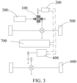
- the power mechanism 1000 provided in the present disclosure further includes a third power member 400.
- the third power member 400 is configured to output power to a second driving end.
- the first driving end is a front wheel 500
- the second driving end is a rear wheel 600.
- the clutch assembly 100 in the present disclosure is used, so that the entire power mechanism 1000 has a compact structure, occupies a small area, and is easy to arrange and mount.
- the power mechanism 1000 further includes a power battery 700.
- the first power member 200 and the third power member 400 are motors, the first power member 200 and the third power member 400 are connected to the power battery 700, to enable the power battery 700 to supply power to the motors.
- the first power member 200 is electrically connected to the third power member 400, to enable the first power member 200 to supply electrical energy to the power battery 700 or the third power member 400 in a power generation state.
- the present disclosure further provides a vehicle 2000.
- the vehicle 2000 includes the foregoing power mechanism 1000.
Landscapes
- Engineering & Computer Science (AREA)
- Mechanical Engineering (AREA)
- General Engineering & Computer Science (AREA)
- Chemical & Material Sciences (AREA)
- Combustion & Propulsion (AREA)
- Transportation (AREA)
- Mechanical Operated Clutches (AREA)
- Arrangement And Driving Of Transmission Devices (AREA)
Abstract
Description
- The present disclosure claims priority to
Chinese Patent Application No. 202210613299.2 filed on May 31st, 2022 - The present disclosure relates to the field of vehicles, and specifically, to a clutch assembly, a power mechanism, and a vehicle.
- As the demand of society for energy saving and environmental protection becomes higher, new energy vehicles have gradually become mainstream models for consumers to select. Types of existing new energy vehicles mainly include pure electric vehicles and hybrid vehicles. To alleviate concerns about service life of batteries, demands of consumers for hybrid vehicles gradually increase. However, in consideration of an engine and a motor, an existing hybrid vehicle has a complex transmission system and a long transmission chain. As a result, the transmission system occupies a large space.
- The technical problem resolved by the present disclosure is that an existing transmission system is complex in structure and occupies a large space.
- To resolve the foregoing technical problem, examples of the present disclosure provide a clutch assembly. The clutch assembly includes a first transmission member, a first clutch component, and a second clutch component. The first clutch component includes a first clutch portion and a second clutch portion. The second clutch component includes a third clutch portion and a fourth clutch portion. The first clutch portion and the third clutch portion are connected to the first transmission member to enable the first transmission member to form a first end. The first clutch portion is selectively engaged with the second clutch portion to enable the second clutch portion to form a second end. The fourth clutch portion is selectively engaged with the third clutch portion to enable the fourth clutch portion to form a third end.
- Optionally, the first end is an output end, and the second end and the third end are input ends.
- Optionally, the second end is an output end, and the first end and the third end are input ends.
- Optionally, along a thickness direction of the first transmission member, the first clutch portion and the third clutch portion are respectively connected to two sides of the first transmission member. Along the thickness direction of the first transmission member, a projection of the first clutch portion and a projection of the third clutch portion at least partially overlap.
- Optionally, the first transmission member is a gear. The first clutch portion and the third clutch portion are fixedly connected to form a clutch body. The first transmission member is arranged on the clutch body.
- Optionally, an outer periphery of the clutch body is constructed with teeth to form the first transmission member.
- Optionally, the first transmission member, the first clutch portion, and the third clutch portion are integrally formed.
- Optionally, the clutch assembly further includes a countershaft. The first transmission member is fixedly connected to the countershaft. The second clutch portion and the fourth clutch portion are rotatably arranged on the countershaft.
- Optionally, the countershaft has a free end and a limiting end. A direction from the second clutch portion to the fourth clutch portion is the same as a direction from the free end to the limiting end.
- Optionally, a first limiting portion is formed on the fourth clutch portion. A second limiting portion is arranged on the limiting end of the countershaft. The first limiting portion cooperates with the second limiting portion to limit axial movement of the countershaft.
- Optionally, the fourth clutch portion is recessed toward a side away from the limiting end to form the first limiting portion. The limiting end protrudes toward a side away from the free end to form the second limiting portion. The first limiting portion is a spherical groove. The second limiting portion is a spherical protrusion. The first limiting portion and the second limiting portion are concentric and spaced away.
- Optionally, the clutch assembly further includes a housing, a first bearing, and a second bearing. The first bearing is fixed between the fourth clutch portion and the countershaft to enable the fourth clutch portion and the countershaft to relatively rotate. The second bearing is fixed between the fourth clutch portion and the housing to enable the fourth clutch portion and the housing to relatively rotate. Along a radial direction of the countershaft, a projection of the first bearing and a projection of the second bearing at least partially overlap.
- The present disclosure provides a clutch assembly. The clutch assembly can selectively output at least one of two powers, that is, the clutch assembly can complete functions of two clutches. A first clutch portion and a third clutch portion are fixed on a first transmission member, so that integration of two clutch components is implemented. Compared with two clutches, the clutch assembly can achieve an effect of the two clutches, and also make the entire clutch assembly more compact, so that the volume and the occupied space are significantly reduced. In addition, the first transmission member implements power transmission, and is also used as a mounting carrier for a first clutch component and a second clutch component. In this way, parts of the clutch assembly are reduced, integration of the entire clutch assembly is improved, and costs are reduced to a certain extent.
- The present disclosure further provides a power mechanism. The power mechanism includes a first power member, a second power member, and the foregoing clutch assembly. Two of the first end, the second end, and the third end are input ends, and the other of the first end, the second end, and the third end is an output end. The first power member and the second power member are connected to the input ends. The output end is drivingly connected to a first driving end.
- Optionally, the power mechanism further includes a third power member. The third power member is configured to output power to a second driving end.
- The present disclosure further provides a vehicle. The vehicle includes the foregoing power mechanism.
-
-
FIG. 1 is a cross-sectional view of a clutch assembly according to an example of the present disclosure; -
FIG. 2 is a schematic diagram of a power mechanism according to an example of the present disclosure; -
FIG. 3 is a schematic diagram of a power mechanism according to another example of the present disclosure; and -
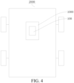
FIG. 4 is a schematic diagram of a vehicle according to an example of the present disclosure. - In the drawings:
- 100: clutch assembly;
- 10: countershaft; 101: second limiting portion;
- 20: first transmission member;
- 30: first clutch component; 301: first clutch portion; 302: second clutch portion;
- 40: second clutch component; 401: third clutch portion; 4011: cavity; 4012: first limiting portion; 402: fourth clutch portion;
- 50: first bearing;
- 60: second bearing;
- 70: third bearing;
- 80: fourth bearing;
- 200: first power member;
- 300: second power member;
- 400: third power member;
- 500: front wheel;
- 600: rear wheel;
- 700: power battery;
- 1000: power mechanism; and
- 2000: vehicle.
- To make the problems, solutions, and beneficial effects resolved by the present disclosure clearer and more understandable, the present disclosure is described in further detail with references to examples below. It should be understood that the specific examples described herein are only for explaining the present disclosure but are not to limit the present disclosure.
- As shown in
FIG. 1 , an example of the present disclosure provides aclutch assembly 100. Theclutch assembly 100 includes afirst transmission member 20, a first clutch component 30, and a second clutch component 40. The first clutch component 30 includes a firstclutch portion 301 and a secondclutch portion 302. The second clutch component 40 includes a thirdclutch portion 401 and a fourthclutch portion 402. The firstclutch portion 301 and the thirdclutch portion 401 are connected to thefirst transmission member 20 to enable thefirst transmission member 20 to form a first end. The firstclutch portion 301 is selectively engaged with the secondclutch portion 302 to enable the secondclutch portion 302 to form a second end. The thirdclutch portion 401 is selectively engaged with the fourthclutch portion 402 to enable the fourthclutch portion 402 to form a third end. Two of the first end, the second end, and the third end of theclutch assembly 100 are input ends, and the other of the first end, the second end, and the third end is an output end. - The
clutch assembly 100 can selectively output at least one of two powers, that is, theclutch assembly 100 can complete functions of two clutches. A firstclutch portion 301 and a thirdclutch portion 401 are fixed on afirst transmission member 20, so that integration of two clutch components is implemented. Compared with two clutches, theclutch assembly 100 can achieve an effect of the two clutches, and also make the entireclutch assembly 100 more compact, so that the volume and the occupied space are significantly reduced. In addition, thefirst transmission member 20 implements power transmission, and is also used as a mounting carrier for a first clutch component 30 and a second clutch component 40. In this way, parts of theclutch assembly 100 are reduced, integration of the entireclutch assembly 100 is improved, and costs are reduced to a certain extent. - In an example not shown in the figure, the first end is an output end, and the second end and the third end are input ends. In this way, a power source connected to the second
clutch portion 302 and a power source connected to the fourthclutch portion 402 can selectively output power through thefirst transmission member 20 in theclutch assembly 100. - In this example, the power source connected to the second
clutch portion 302 and the power source connected to the fourthclutch portion 402 may be the same or different. - In the example shown in
FIG. 1 , the second end is an output end, and the first end and the third end are input ends. In this way, a power source connected to the fourthclutch portion 402 and a power source connected to thefirst transmission member 20 selectively output power through the secondclutch portion 302 in theclutch assembly 100. In this example, the power source connected to the fourthclutch portion 402 and the power source connected to thefirst transmission member 20 may be the same or different. - It should be understood that when the first
clutch portion 301 is engaged with the thirdclutch portion 401 and the secondclutch portion 302 is disengaged from the fourthclutch portion 402, power output of a single power source is implemented. When the firstclutch portion 301 is engaged with the thirdclutch portion 401 and the secondclutch portion 302 is engaged with the fourthclutch portion 402, output of a single power source can be implemented, and joint output of two power sources can also be implemented. - As shown in
FIG. 1 , along a thickness direction of thefirst transmission member 20, the firstclutch portion 301 and the thirdclutch portion 401 are respectively connected to two sides of thefirst transmission member 20. Along the thickness direction of thefirst transmission member 20, a projection of the firstclutch portion 301 and a projection of the thirdclutch portion 401 at least partially overlap. To be specific, the firstclutch portion 301 and the thirdclutch portion 401 are arranged side by side on the two sides of thefirst transmission member 20 along the thickness direction of thefirst transmission member 20. This implements integration of the first clutch component 30 and the second clutch component 40, and also reduces sizes of the firstclutch portion 301 and the thirdclutch portion 401 along a radial direction, thereby effectively reducing a volume of theclutch assembly 100. - In the examples as shown in
FIG. 1 and FIG 2 , thefirst transmission member 20 is a gear, and the firstclutch portion 301 and the thirdclutch portion 401 are fixedly connected to an inner side of the gear, that is, connected to the inner side on which teeth are formed. - In an example, the first
clutch portion 301 the thirdclutch portion 401 may be fixedly connected to form a clutch body. Thefirst transmission member 20 is arranged on the clutch body. - In an example, an outer periphery of the clutch body may be constructed with teeth to form the first transmission member 20 (gear). In this way, the space occupied by the first
clutch portion 301, the thirdclutch portion 401, and thefirst transmission member 20 can be further reduced, thereby reducing the volume of theclutch assembly 100. - In another example, the
first transmission member 20 may also be a partial element in a planetary row, and the like, as long as it can be used for power transmission. - In some examples, the first
clutch portion 301, the thirdclutch portion 401, and thefirst transmission member 20 are integrally formed. The firstclutch portion 301, the thirdclutch portion 401, and thefirst transmission member 20 that are integrally formed further reduce an axial size, thereby further reducing the volume. - In the examples shown in
FIG 1 and FIG 2 , the firstclutch portion 301 and the thirdclutch portion 401 are fixedly connected to thefirst transmission member 20. Specifically, the firstclutch portion 301 and the thirdclutch portion 401 are welded to thefirst transmission member 20. Certainly, the firstclutch portion 301 and the thirdclutch portion 401 may also be fixed on thefirst transmission member 20 through a screw connection or the like. - As shown in
FIG. 1 , theclutch assembly 100 further includes acountershaft 10. Thefirst transmission member 20 is connected to thecountershaft 10. The secondclutch portion 302 and the fourthclutch portion 402 are rotatably connected to thecountershaft 10. - The
countershaft 10 has a free end and a limiting end. A direction from the secondclutch portion 302 to the fourthclutch portion 402 is the same as a direction from the free end to the limiting end. It should be understood that the free end and the limiting end in the present disclosure are respectively formed on two ends of thiscountershaft 10. The free end is formed on a right side of thecountershaft 10 inFIG. 1 . The limiting end is formed on a left side of thecountershaft 10 inFIG. 1 . - As shown in
FIG. 1 , a first limitingportion 4012 is arranged in the fourthclutch portion 402. A second limitingportion 101 is arranged on thecountershaft 10. The first limitingportion 4012 cooperates with the second limitingportion 101 to limit axial movement of thecountershaft 10. An end of thecountershaft 10 is the free end. Therefore, the axial movement of thecountershaft 10 is limited by the first limitingportion 4012 and the second limitingportion 101, thereby improving structural stability. - In an example, the first limiting
portion 4012 is a spherical groove. The second limitingportion 101 is a spherical protrusion. The spherical groove and the spherical protrusion are concentrically arranged. In this way, even if thecountershaft 10 undergoes axial displacement within a certain range to cause the first limitingportion 4012 to come into contact with the second limitingportion 101, the spherical groove and the spherical protrusion concentrically arranged can also enable thecountershaft 10 and the fourthclutch portion 402 to relatively rotate, so that theclutch assembly 100 can normally operate. - As shown in
FIG. 1 , acavity 4011 is provided in the fourthclutch portion 402, and one end of thecountershaft 10 is located in thecavity 4011. Thecavity 4011 is provided in the fourthclutch portion 402, so that thecountershaft 10 is arranged in thecavity 4011. Then, the other end of thecountershaft 10 is also mounted through mounting of the fourthclutch portion 402. This avoids increasing the axial size when arranging a mounting position on one end of thecountershaft 10, thereby further reducing the axial size, and making the entireclutch assembly 100 more compact. In addition, the arrangement of thecavity 4011 also provides a condition for the arrangement of the first limitingportion 4012 below. The foregoing first limitingportion 4012 is formed in thecavity 4011. - In an example, the
clutch assembly 100 further includes a housing. An inner side of the secondclutch portion 302 is rotatably sleeved on thecountershaft 10 through thefirst bearing 50, and an outer side of a driven member is rotatably connected to the housing through thesecond bearing 60. Along a radial direction of thecountershaft 10, a projection of thefirst bearing 50 and a projection of thesecond bearing 60 at least partially overlap. In this way, a load along the radial direction of thecountershaft 10 during power transmission can be transmitted to the housing through thefirst bearing 50, the fourthclutch portion 402, and thesecond bearing 60, avoiding damage to the entire system by shear force caused by completely misaligned arrangement of thefirst bearing 50 and thesecond bearing 60, thereby improving the life of theclutch assembly 100. - As shown in
FIG. 1 , theclutch assembly 100 further includes athird bearing 70 and afourth bearing 80. The secondclutch portion 302 is sleeved on thecountershaft 10 through thethird bearing 70, and thecountershaft 10 is rotatably connected to the housing through thefourth bearing 80, to implement relative rotation between the housing and thecountershaft 10. - As shown in
FIG. 2 andFIG 3 , an example of the present disclosure further provides apower mechanism 1000. Thepower mechanism 1000 includes afirst power member 200, asecond power member 300, and the foregoingclutch assembly 100. Thefirst power member 200 and thesecond power member 300 are connected to the input ends. The output end is drivingly connected to a first driving end. - One of the
first power member 200 and thesecond power member 300 is an engine, and the other of thefirst power member 200 and thesecond power member 300 is a motor. - The
first transmission member 20 is configured to connect to thefirst power member 200. The fourthclutch portion 402 is configured to connect to thesecond power member 300. The secondclutch portion 302 is configured to output power to wheels. Thefirst power member 200 is an engine, and thesecond power member 300 is a motor. - In the examples as shown in
FIG. 1 and FIG. 2 , thefirst power member 200 is a motor, and thesecond power member 300 is an engine. In this way, the engine and the motor can selectively input power to the wheels, and the engine and the motor can also be selectively engaged. In this way, the engine during operation can output power to the motor, to enable the motor to generate electricity. - In the example shown in
FIG. 2 , thefirst power member 200 is a motor, thesecond power member 300 is an engine, thefirst transmission member 20 is configured to connect to the motor, and the secondclutch portion 302 is configured to output power to the wheels. In this way, the engine can be selectively engaged with the motor through theclutch assembly 100, so that the power can be selectively transmitted to the motor, to enable the motor to generate electricity. The motor selectively transmits power of the motor or the engine to the wheels through the clutch assembly 100 (when the motor is connected to the engine through a clutch). - In the
clutch assembly 100, the firstclutch portion 301 of the first clutch component 30 and the thirdclutch portion 401 of the second clutch component 40 are fixedly connected to thefirst transmission member 20. Thefirst transmission member 20 implements power transmission from thefirst power member 200 or thesecond power member 300 to the wheels, and is also used as a carrier for integration of the first clutch component 30 and the second clutch component 40. In this way, integration of the two clutches and thefirst transmission member 20 is implemented, and the structure is compact, so that the volume and the occupied space of theclutch assembly 100 are reduced. In addition, because the volume of theclutch assembly 100 is reduced, a power transmission chain is shortened, thereby improving efficiency of power transmission. - In an example, the
first transmission member 20 may be configured to output power to the wheels, and in this case, the secondclutch portion 302 may be configured to connect to thefirst power member 200. In this way, the first clutch component 30 can selectively transmit power from thefirst power member 200 to the wheels, and the second clutch component 40 can selectively transmit power from thesecond power member 300 to the wheels. It should be understood that thefirst power member 200 and thesecond power member 300 may be engines or motors. Generally, one of thefirst power member 200 and thesecond power member 300 is a motor, and the other of thefirst power member 200 and thesecond power member 300 is an engine. - As shown in
FIG. 3 , thepower mechanism 1000 provided in the present disclosure further includes athird power member 400. Thethird power member 400 is configured to output power to a second driving end. The first driving end is afront wheel 500, and the second driving end is arear wheel 600. In this way, timely four-wheel drive can be implemented by using three power members, so that a four-wheel drive function is implemented, and cost are reduced. Theclutch assembly 100 in the present disclosure is used, so that theentire power mechanism 1000 has a compact structure, occupies a small area, and is easy to arrange and mount. - In addition, the
power mechanism 1000 further includes apower battery 700. When thefirst power member 200 and thethird power member 400 are motors, thefirst power member 200 and thethird power member 400 are connected to thepower battery 700, to enable thepower battery 700 to supply power to the motors. In addition, thefirst power member 200 is electrically connected to thethird power member 400, to enable thefirst power member 200 to supply electrical energy to thepower battery 700 or thethird power member 400 in a power generation state. - As shown in
FIG. 4 , the present disclosure further provides avehicle 2000. Thevehicle 2000 includes the foregoingpower mechanism 1000. - The foregoing descriptions are merely preferred examples of the present disclosure, but are not intended to limit the present disclosure. Any modification, equivalent replacement, or improvement made within the spirit and principle of the present disclosure shall fall within the protection scope of the present disclosure.
Claims (15)
- A clutch assembly, comprising a first transmission member, a first clutch component, and a second clutch component, the first clutch component comprising a first clutch portion and a second clutch portion, the second clutch component comprising a third clutch portion and a fourth clutch portion, the first clutch portion and the third clutch portion being connected to the first transmission member to enable the first transmission member to form a first end, the second clutch portion being selectively engaged with the first clutch portion to enable the second clutch portion to form a second end, and the fourth clutch portion being selectively engaged with the third clutch portion to enable the fourth clutch portion to form a third end.
- The clutch assembly according to claim 1, wherein the first end is an output end, and the second end and the third end are input ends.
- The clutch assembly according to claim 1, wherein the second end is an output end, and the first end and the third end are input ends.
- The clutch assembly according to any one of claims 1 to 3, wherein along a thickness direction of the first transmission member, the first clutch portion and the third clutch portion are respectively connected to two sides of the first transmission member; and
along the thickness direction of the first transmission member, a projection of the first clutch portion and a projection of the third clutch portion at least partially overlap. - The clutch assembly according to any one of claims 1 to 4, wherein the first transmission member is a gear, the first clutch portion and the third clutch portion are fixedly connected to form a clutch body, and the first transmission member is arranged on the clutch body.
- The clutch assembly according to claim 5, wherein an outer periphery of the clutch body is constructed with teeth to form the first transmission member.
- The clutch assembly according to any one of claims 1 to 6, wherein the first transmission member, the first clutch portion, and the third clutch portion are integrally formed.
- The clutch assembly according to any one of claims 1 to 7, wherein the clutch assembly further comprises a countershaft, the first transmission member is fixedly connected to the countershaft, and the second clutch portion and the fourth clutch portion are rotatably arranged on the countershaft.
- The clutch assembly according to claim 8, wherein the countershaft has a free end and a limiting end, and a direction from the second clutch portion to the fourth clutch portion is the same as a direction from the free end to the limiting end.
- The clutch assembly according to claim 9, wherein a first limiting portion is formed on the fourth clutch portion, a second limiting portion is arranged on the limiting end of the countershaft, and the first limiting portion cooperates with the second limiting portion to limit axial movement of the countershaft.
- The clutch assembly according to claim 10, wherein the fourth clutch portion is recessed toward a side away from the limiting end to form the first limiting portion, the limiting end protrudes toward a side away from the free end to form the second limiting portion, the first limiting portion is a spherical groove, the second limiting portion is a spherical protrusion, and the first limiting portion and the second limiting portion are concentric and spaced away.
- The clutch assembly according to any one of claims 8 to 11, wherein the clutch assembly further comprises a housing, a first bearing, and a second bearing, the first bearing is connected between the fourth clutch portion and the countershaft to enable the fourth clutch portion and the countershaft to relatively rotate, the second bearing is connected between the fourth clutch portion and the housing to enable the fourth clutch portion and the housing to relatively rotate, and along a radial direction of the countershaft, a projection of the first bearing and a projection of the second bearing at least partially overlap.
- A power mechanism, comprising a first power member, a second power member, and the clutch assembly according to any one of claims 1 to 12, two of the first end, the second end, and the third end being input ends, the other of the first end, the second end, and the third end being an output end, the first power member and the second power member being connected to the input ends, and the output end being drivingly connected to a first driving end.
- The power mechanism according to claim 13, wherein the power mechanism further comprises a third power member, and the third power member is configured to output power to a second driving end.
- A vehicle, comprising the power mechanism according to claim 13 or 14.
Applications Claiming Priority (2)
| Application Number | Priority Date | Filing Date | Title |
|---|---|---|---|
| CN202210613299.2A CN117183714A (en) | 2022-05-31 | 2022-05-31 | Clutch assembly, power mechanism and vehicle |
| PCT/CN2023/097354 WO2023232061A1 (en) | 2022-05-31 | 2023-05-31 | Clutch assembly, power mechanism and vehicle |
Publications (2)
| Publication Number | Publication Date |
|---|---|
| EP4506198A1 true EP4506198A1 (en) | 2025-02-12 |
| EP4506198A4 EP4506198A4 (en) | 2025-08-20 |
Family
ID=88994777
Family Applications (1)
| Application Number | Title | Priority Date | Filing Date |
|---|---|---|---|
| EP23815239.1A Pending EP4506198A4 (en) | 2022-05-31 | 2023-05-31 | CLUTCH ARRANGEMENT, DRIVE MECHANISM AND VEHICLE |
Country Status (6)
| Country | Link |
|---|---|
| US (1) | US12623528B2 (en) |
| EP (1) | EP4506198A4 (en) |
| JP (1) | JP2025516493A (en) |
| KR (1) | KR20250003935A (en) |
| CN (1) | CN117183714A (en) |
| WO (1) | WO2023232061A1 (en) |
Family Cites Families (52)
| Publication number | Priority date | Publication date | Assignee | Title |
|---|---|---|---|---|
| DE3022373A1 (en) | 1980-06-14 | 1981-12-24 | Volkswagenwerk Ag | VEHICLE, PARTICULARLY PERSONAL VEHICLES |
| JPS60110723U (en) * | 1983-12-28 | 1985-07-27 | ヤンマー農機株式会社 | Clutch device in power shift transmission |
| JP3711853B2 (en) * | 2000-09-14 | 2005-11-02 | いすゞ自動車株式会社 | Hybrid drive device |
| JP4050519B2 (en) | 2002-01-28 | 2008-02-20 | 株式会社日立製作所 | Four-wheel drive control device |
| JP4381031B2 (en) * | 2003-05-15 | 2009-12-09 | Ntn株式会社 | Electric power steering device |
| JP4514021B2 (en) * | 2003-12-11 | 2010-07-28 | Ntn株式会社 | Ball screw actuator |
| DE102005063248B4 (en) | 2005-12-21 | 2010-09-30 | Getrag Getriebe- Und Zahnradfabrik Hermann Hagenmeyer Gmbh & Cie Kg | Dual clutch assembly |
| CN101607523A (en) | 2008-06-19 | 2009-12-23 | 比亚迪股份有限公司 | hybrid power output |
| CN102039808A (en) * | 2009-10-19 | 2011-05-04 | 王立华 | Double clutch system |
| DE102010021033A1 (en) * | 2010-05-19 | 2011-11-24 | Audi Ag | Drive arrangement on a dual-clutch transmission for motor vehicles |
| DE112011102026B4 (en) * | 2010-06-15 | 2015-09-03 | Honda Motor Co., Ltd. | Vehicle drive system and control method for the vehicle drive system |
| DE102011106399A1 (en) * | 2011-07-02 | 2013-01-03 | Magna E-Car Systems Gmbh & Co Og | powertrain |
| CN102381177B (en) | 2011-08-18 | 2014-10-01 | 奇瑞汽车股份有限公司 | Electric four-drive hybrid system and control method thereof |
| JP5318185B2 (en) | 2011-12-12 | 2013-10-16 | 本田技研工業株式会社 | Vehicle drive device |
| US10836375B2 (en) * | 2013-02-08 | 2020-11-17 | Cummins Electrified Power Na Inc. | Powertrain configurations for single-motor, two-clutch hybrid electric vehicles |
| KR101786338B1 (en) | 2016-05-02 | 2017-10-17 | 현대자동차주식회사 | Power train for hybrid vehicle |
| JP2018071695A (en) * | 2016-10-31 | 2018-05-10 | 株式会社ダイナックス | Friction clutch |
| KR102451874B1 (en) * | 2016-12-14 | 2022-10-07 | 현대자동차 주식회사 | Double clutch system for hybrid electric vehicles |
| CN206551860U (en) * | 2017-01-23 | 2017-10-13 | 中国第一汽车股份有限公司 | A kind of clutch driving unit of automobile-use three |
| CN106627079A (en) * | 2017-01-25 | 2017-05-10 | 苏州凯博易控驱动技术有限公司 | Dual-motor parallel serial driving module and vehicle |
| KR20180095234A (en) | 2017-02-17 | 2018-08-27 | 한양대학교 에리카산학협력단 | Power train of an hybrid electric vehicle using one motor and a dual clutch transmission including manipulating method thereof |
| JP6480978B2 (en) | 2017-04-27 | 2019-03-13 | 本田技研工業株式会社 | Vehicle clutch device |
| FR3067077B1 (en) * | 2017-05-31 | 2019-12-06 | Valeo Embrayages | CLUTCH MECHANISM COMPRISING TWO ASSEMBLIES CONNECTED BY AN ASSEMBLY DEVICE |
| CN207842651U (en) | 2018-02-11 | 2018-09-11 | 上海易矩汽车技术有限公司 | A kind of single-motor double clutch hybrid power system |
| CN108544916B (en) | 2018-03-23 | 2021-07-30 | 上汽通用汽车有限公司 | Multi-mode hybrid power electric four-wheel drive system and control method thereof |
| CN208734758U (en) * | 2018-07-04 | 2019-04-12 | 山推工程机械股份有限公司 | Novel clutch assembly and 2 tons of novel loading machine plagiodont gearboxes |
| DE102018123740A1 (en) | 2018-07-26 | 2020-01-30 | Schaeffler Technologies AG & Co. KG | Hybrid transmission, hybrid drive arrangement and method for operating a hybrid drive arrangement |
| CN109177716B (en) * | 2018-08-17 | 2019-11-26 | 宁波上中下自动变速器有限公司 | Dynamical system for hybrid vehicle |
| JP2020029938A (en) * | 2018-08-24 | 2020-02-27 | 本田技研工業株式会社 | Vehicular power transmission device |
| JP7031536B2 (en) | 2018-09-05 | 2022-03-08 | 株式会社アイシン | Vehicle drive and resolver stator |
| CN111016619B (en) * | 2018-10-09 | 2024-04-23 | 广州汽车集团股份有限公司 | Three-clutch hybrid power coupling system and vehicle |
| CN111055672B (en) | 2018-10-16 | 2024-03-26 | 广汽埃安新能源汽车有限公司 | Two keep off hybrid power coupled system and vehicle |
| CN111114275A (en) * | 2018-10-31 | 2020-05-08 | 比亚迪股份有限公司 | Hybrid drive systems and vehicles |
| JP7156073B2 (en) * | 2019-02-14 | 2022-10-19 | トヨタ自動車株式会社 | vehicle controller |
| JP2020165474A (en) | 2019-03-29 | 2020-10-08 | アイシン・エィ・ダブリュ株式会社 | Frictional engagement device and drive transmission device |
| US11413948B2 (en) * | 2019-07-15 | 2022-08-16 | Dana Heavy Vehicle Systems Group, Llc | Electric axle assembly |
| CN112572127B (en) * | 2019-09-30 | 2022-06-14 | 比亚迪股份有限公司 | Hybrid power assembly and vehicle with same |
| JP7011636B2 (en) * | 2019-10-11 | 2022-01-26 | 本田技研工業株式会社 | Drive |
| CN110667368A (en) * | 2019-10-16 | 2020-01-10 | 中汽研(天津)汽车工程研究院有限公司 | A four-wheel drive vehicle hybrid power system and working method |
| CN111319607B (en) * | 2019-12-27 | 2023-09-26 | 福建中维动力科技股份有限公司 | Reversing control system based on high-efficiency hybrid power system |
| CN111347869A (en) | 2020-03-18 | 2020-06-30 | 吉泰车辆技术(苏州)有限公司 | Three-gear transmission for hybrid electric vehicle |
| FR3110879B1 (en) * | 2020-05-28 | 2022-09-16 | Valeo Embrayages | Double wet clutch |
| NL2025845B1 (en) * | 2020-06-17 | 2022-02-17 | Punch Powertrain Psa E Trans N V | Improved lay-shaft assembly for use in a vehicle transmission |
| CN112108234A (en) * | 2020-09-09 | 2020-12-22 | 于志勇 | Construction waste treatment device |
| CN112319204A (en) | 2020-11-02 | 2021-02-05 | 中国第一汽车股份有限公司 | Vehicle hybrid system and vehicle control method |
| CN215596239U (en) * | 2021-09-02 | 2022-01-21 | 索特传动设备有限公司 | Reversing clutch |
| WO2023092352A1 (en) * | 2021-11-24 | 2023-06-01 | 宁德时代新能源科技股份有限公司 | Power drive system and vehicle |
| CN216709004U (en) * | 2021-11-30 | 2022-06-10 | 比亚迪股份有限公司 | Power driving system and vehicle with same |
| CN218228631U (en) * | 2022-05-31 | 2023-01-06 | 比亚迪股份有限公司 | Hybrid power assembly and vehicle |
| CN217994129U (en) * | 2022-05-31 | 2022-12-09 | 比亚迪股份有限公司 | Power transmission system and vehicle with same |
| CN217381366U (en) * | 2022-05-31 | 2022-09-06 | 比亚迪股份有限公司 | Clutches, Powertrains, and Vehicles |
| CN219424610U (en) * | 2023-02-23 | 2023-07-28 | 浙江美晶新材料股份有限公司 | Vibration deironing mechanism of quartz sand |
-
2022
- 2022-05-31 CN CN202210613299.2A patent/CN117183714A/en active Pending
-
2023
- 2023-05-31 WO PCT/CN2023/097354 patent/WO2023232061A1/en not_active Ceased
- 2023-05-31 EP EP23815239.1A patent/EP4506198A4/en active Pending
- 2023-05-31 KR KR1020247038821A patent/KR20250003935A/en active Pending
- 2023-05-31 JP JP2024564604A patent/JP2025516493A/en active Pending
-
2024
- 2024-11-06 US US18/939,164 patent/US12623528B2/en active Active
Also Published As
| Publication number | Publication date |
|---|---|
| KR20250003935A (en) | 2025-01-07 |
| EP4506198A4 (en) | 2025-08-20 |
| JP2025516493A (en) | 2025-05-30 |
| US20250058620A1 (en) | 2025-02-20 |
| WO2023232061A1 (en) | 2023-12-07 |
| WO2023232061A9 (en) | 2024-02-01 |
| CN117183714A (en) | 2023-12-08 |
| US12623528B2 (en) | 2026-05-12 |
Similar Documents
| Publication | Publication Date | Title |
|---|---|---|
| JP7845614B2 (en) | Hybrid powertrain and vehicle | |
| CN215244312U (en) | Hybrid power driving system of vehicle and vehicle | |
| CN113415154A (en) | Single motor drive transmission structure and engineering vehicle | |
| US12623528B2 (en) | Clutch assembly, power mechanism and vehicle | |
| CN117183717A (en) | Hybrid power system of vehicle and vehicle | |
| US20240123821A1 (en) | Powertrain system and electric vehicle | |
| CN115095610B (en) | Power transmission disconnection mechanism and vehicle | |
| EP4474189A1 (en) | Hybrid power assembly and vehicle | |
| US12030377B2 (en) | Electric powertrain for a vehicle | |
| US20250236172A1 (en) | Transverse driving assembly | |
| WO2023124184A1 (en) | Driving device of hybrid vehicle | |
| CN211592226U (en) | Hybrid power device for vehicle and vehicle with hybrid power device | |
| CN222185641U (en) | Unpowered interrupt transmission assembly | |
| EP4534312A1 (en) | Powertrain system and vehicle | |
| EP4378728A1 (en) | Hybrid powertrain and vehicle | |
| CN112793415A (en) | Double differential transmission system | |
| CN223835381U (en) | A dual-motor direct-drive electric tractor transmission system | |
| CN217778347U (en) | Powertrains and Vehicles | |
| CN223187337U (en) | Power drive system and vehicle | |
| CN219838433U (en) | Vehicle transmission assembly, power assembly and vehicle | |
| US12533948B2 (en) | Power transmission device and drive device | |
| CN215410066U (en) | Special-purpose vehicle locking structure | |
| CN222973192U (en) | Power system and vehicle | |
| EP4699839A1 (en) | Power system and automobile | |
| CN222992069U (en) | Differential mechanism assembly and vehicle |
Legal Events
| Date | Code | Title | Description |
|---|---|---|---|
| STAA | Information on the status of an ep patent application or granted ep patent |
Free format text: STATUS: THE INTERNATIONAL PUBLICATION HAS BEEN MADE |
|
| PUAI | Public reference made under article 153(3) epc to a published international application that has entered the european phase |
Free format text: ORIGINAL CODE: 0009012 |
|
| STAA | Information on the status of an ep patent application or granted ep patent |
Free format text: STATUS: REQUEST FOR EXAMINATION WAS MADE |
|
| 17P | Request for examination filed |
Effective date: 20241106 |
|
| AK | Designated contracting states |
Kind code of ref document: A1 Designated state(s): AL AT BE BG CH CY CZ DE DK EE ES FI FR GB GR HR HU IE IS IT LI LT LU LV MC ME MK MT NL NO PL PT RO RS SE SI SK SM TR |
|
| A4 | Supplementary search report drawn up and despatched |
Effective date: 20250723 |
|
| RIC1 | Information provided on ipc code assigned before grant |
Ipc: B60K 6/38 20071001AFI20250717BHEP Ipc: F16D 13/52 20060101ALI20250717BHEP Ipc: F16D 43/21 20060101ALI20250717BHEP |
|
| DAV | Request for validation of the european patent (deleted) | ||
| DAX | Request for extension of the european patent (deleted) | ||
| R17P | Request for examination filed (corrected) |
Effective date: 20241106 |