CN111114275A - Hybrid drive systems and vehicles - Google Patents

Hybrid drive systems and vehicles Download PDF

Info

Publication number
CN111114275A
CN111114275A CN201811284479.0A CN201811284479A CN111114275A CN 111114275 A CN111114275 A CN 111114275A CN 201811284479 A CN201811284479 A CN 201811284479A CN 111114275 A CN111114275 A CN 111114275A
Authority
CN
China
Prior art keywords
clutch
gear set
input shaft
engine
drive mode
Prior art date
Legal status (The legal status is an assumption and is not a legal conclusion. Google has not performed a legal analysis and makes no representation as to the accuracy of the status listed.)
Pending
Application number
CN201811284479.0A
Other languages
Chinese (zh)
Inventor
杨冬生
白云辉
穆金辉
朱新明
Current Assignee (The listed assignees may be inaccurate. Google has not performed a legal analysis and makes no representation or warranty as to the accuracy of the list.)
BYD Co Ltd
Original Assignee
BYD Co Ltd
Priority date (The priority date is an assumption and is not a legal conclusion. Google has not performed a legal analysis and makes no representation as to the accuracy of the date listed.)
Filing date
Publication date
Application filed by BYD Co Ltd filed Critical BYD Co Ltd
Priority to CN201811284479.0A priority Critical patent/CN111114275A/en
Publication of CN111114275A publication Critical patent/CN111114275A/en
Pending legal-status Critical Current

Links

Images

Classifications

    • B—PERFORMING OPERATIONS; TRANSPORTING
    • B60—VEHICLES IN GENERAL
    • B60K—ARRANGEMENT OR MOUNTING OF PROPULSION UNITS OR OF TRANSMISSIONS IN VEHICLES; ARRANGEMENT OR MOUNTING OF PLURAL DIVERSE PRIME-MOVERS IN VEHICLES; AUXILIARY DRIVES FOR VEHICLES; INSTRUMENTATION OR DASHBOARDS FOR VEHICLES; ARRANGEMENTS IN CONNECTION WITH COOLING, AIR INTAKE, GAS EXHAUST OR FUEL SUPPLY OF PROPULSION UNITS IN VEHICLES
    • B60K6/00—Arrangement or mounting of plural diverse prime-movers for mutual or common propulsion, e.g. hybrid propulsion systems comprising electric motors and internal combustion engines
    • B60K6/20—Arrangement or mounting of plural diverse prime-movers for mutual or common propulsion, e.g. hybrid propulsion systems comprising electric motors and internal combustion engines the prime-movers consisting of electric motors and internal combustion engines, e.g. HEVs
    • B60K6/22—Arrangement or mounting of plural diverse prime-movers for mutual or common propulsion, e.g. hybrid propulsion systems comprising electric motors and internal combustion engines the prime-movers consisting of electric motors and internal combustion engines, e.g. HEVs characterised by apparatus, components or means specially adapted for HEVs
    • B60K6/24—Arrangement or mounting of plural diverse prime-movers for mutual or common propulsion, e.g. hybrid propulsion systems comprising electric motors and internal combustion engines the prime-movers consisting of electric motors and internal combustion engines, e.g. HEVs characterised by apparatus, components or means specially adapted for HEVs characterised by the combustion engines
    • B—PERFORMING OPERATIONS; TRANSPORTING
    • B60—VEHICLES IN GENERAL
    • B60K—ARRANGEMENT OR MOUNTING OF PROPULSION UNITS OR OF TRANSMISSIONS IN VEHICLES; ARRANGEMENT OR MOUNTING OF PLURAL DIVERSE PRIME-MOVERS IN VEHICLES; AUXILIARY DRIVES FOR VEHICLES; INSTRUMENTATION OR DASHBOARDS FOR VEHICLES; ARRANGEMENTS IN CONNECTION WITH COOLING, AIR INTAKE, GAS EXHAUST OR FUEL SUPPLY OF PROPULSION UNITS IN VEHICLES
    • B60K17/00—Arrangement or mounting of transmissions in vehicles
    • B60K17/04—Arrangement or mounting of transmissions in vehicles characterised by arrangement, location or kind of gearing
    • B60K17/16—Arrangement or mounting of transmissions in vehicles characterised by arrangement, location or kind of gearing of differential gearing
    • B—PERFORMING OPERATIONS; TRANSPORTING
    • B60—VEHICLES IN GENERAL
    • B60K—ARRANGEMENT OR MOUNTING OF PROPULSION UNITS OR OF TRANSMISSIONS IN VEHICLES; ARRANGEMENT OR MOUNTING OF PLURAL DIVERSE PRIME-MOVERS IN VEHICLES; AUXILIARY DRIVES FOR VEHICLES; INSTRUMENTATION OR DASHBOARDS FOR VEHICLES; ARRANGEMENTS IN CONNECTION WITH COOLING, AIR INTAKE, GAS EXHAUST OR FUEL SUPPLY OF PROPULSION UNITS IN VEHICLES
    • B60K6/00—Arrangement or mounting of plural diverse prime-movers for mutual or common propulsion, e.g. hybrid propulsion systems comprising electric motors and internal combustion engines
    • B60K6/20—Arrangement or mounting of plural diverse prime-movers for mutual or common propulsion, e.g. hybrid propulsion systems comprising electric motors and internal combustion engines the prime-movers consisting of electric motors and internal combustion engines, e.g. HEVs
    • B60K6/22—Arrangement or mounting of plural diverse prime-movers for mutual or common propulsion, e.g. hybrid propulsion systems comprising electric motors and internal combustion engines the prime-movers consisting of electric motors and internal combustion engines, e.g. HEVs characterised by apparatus, components or means specially adapted for HEVs
    • B60K6/26—Arrangement or mounting of plural diverse prime-movers for mutual or common propulsion, e.g. hybrid propulsion systems comprising electric motors and internal combustion engines the prime-movers consisting of electric motors and internal combustion engines, e.g. HEVs characterised by apparatus, components or means specially adapted for HEVs characterised by the motors or the generators
    • B—PERFORMING OPERATIONS; TRANSPORTING
    • B60—VEHICLES IN GENERAL
    • B60K—ARRANGEMENT OR MOUNTING OF PROPULSION UNITS OR OF TRANSMISSIONS IN VEHICLES; ARRANGEMENT OR MOUNTING OF PLURAL DIVERSE PRIME-MOVERS IN VEHICLES; AUXILIARY DRIVES FOR VEHICLES; INSTRUMENTATION OR DASHBOARDS FOR VEHICLES; ARRANGEMENTS IN CONNECTION WITH COOLING, AIR INTAKE, GAS EXHAUST OR FUEL SUPPLY OF PROPULSION UNITS IN VEHICLES
    • B60K6/00—Arrangement or mounting of plural diverse prime-movers for mutual or common propulsion, e.g. hybrid propulsion systems comprising electric motors and internal combustion engines
    • B60K6/20—Arrangement or mounting of plural diverse prime-movers for mutual or common propulsion, e.g. hybrid propulsion systems comprising electric motors and internal combustion engines the prime-movers consisting of electric motors and internal combustion engines, e.g. HEVs
    • B60K6/22—Arrangement or mounting of plural diverse prime-movers for mutual or common propulsion, e.g. hybrid propulsion systems comprising electric motors and internal combustion engines the prime-movers consisting of electric motors and internal combustion engines, e.g. HEVs characterised by apparatus, components or means specially adapted for HEVs
    • B60K6/36—Arrangement or mounting of plural diverse prime-movers for mutual or common propulsion, e.g. hybrid propulsion systems comprising electric motors and internal combustion engines the prime-movers consisting of electric motors and internal combustion engines, e.g. HEVs characterised by apparatus, components or means specially adapted for HEVs characterised by the transmission gearings
    • B60K6/365—Arrangement or mounting of plural diverse prime-movers for mutual or common propulsion, e.g. hybrid propulsion systems comprising electric motors and internal combustion engines the prime-movers consisting of electric motors and internal combustion engines, e.g. HEVs characterised by apparatus, components or means specially adapted for HEVs characterised by the transmission gearings with the gears having orbital motion
    • B—PERFORMING OPERATIONS; TRANSPORTING
    • B60—VEHICLES IN GENERAL
    • B60K—ARRANGEMENT OR MOUNTING OF PROPULSION UNITS OR OF TRANSMISSIONS IN VEHICLES; ARRANGEMENT OR MOUNTING OF PLURAL DIVERSE PRIME-MOVERS IN VEHICLES; AUXILIARY DRIVES FOR VEHICLES; INSTRUMENTATION OR DASHBOARDS FOR VEHICLES; ARRANGEMENTS IN CONNECTION WITH COOLING, AIR INTAKE, GAS EXHAUST OR FUEL SUPPLY OF PROPULSION UNITS IN VEHICLES
    • B60K6/00—Arrangement or mounting of plural diverse prime-movers for mutual or common propulsion, e.g. hybrid propulsion systems comprising electric motors and internal combustion engines
    • B60K6/20—Arrangement or mounting of plural diverse prime-movers for mutual or common propulsion, e.g. hybrid propulsion systems comprising electric motors and internal combustion engines the prime-movers consisting of electric motors and internal combustion engines, e.g. HEVs
    • B60K6/22—Arrangement or mounting of plural diverse prime-movers for mutual or common propulsion, e.g. hybrid propulsion systems comprising electric motors and internal combustion engines the prime-movers consisting of electric motors and internal combustion engines, e.g. HEVs characterised by apparatus, components or means specially adapted for HEVs
    • B60K6/38—Arrangement or mounting of plural diverse prime-movers for mutual or common propulsion, e.g. hybrid propulsion systems comprising electric motors and internal combustion engines the prime-movers consisting of electric motors and internal combustion engines, e.g. HEVs characterised by apparatus, components or means specially adapted for HEVs characterised by the driveline clutches
    • Y—GENERAL TAGGING OF NEW TECHNOLOGICAL DEVELOPMENTS; GENERAL TAGGING OF CROSS-SECTIONAL TECHNOLOGIES SPANNING OVER SEVERAL SECTIONS OF THE IPC; TECHNICAL SUBJECTS COVERED BY FORMER USPC CROSS-REFERENCE ART COLLECTIONS [XRACs] AND DIGESTS
    • Y02—TECHNOLOGIES OR APPLICATIONS FOR MITIGATION OR ADAPTATION AGAINST CLIMATE CHANGE
    • Y02T—CLIMATE CHANGE MITIGATION TECHNOLOGIES RELATED TO TRANSPORTATION
    • Y02T10/00—Road transport of goods or passengers
    • Y02T10/60—Other road transportation technologies with climate change mitigation effect
    • Y02T10/62—Hybrid vehicles

Landscapes

  • Engineering & Computer Science (AREA)
  • Chemical & Material Sciences (AREA)
  • Combustion & Propulsion (AREA)
  • Transportation (AREA)
  • Mechanical Engineering (AREA)
  • Electric Propulsion And Braking For Vehicles (AREA)
  • Hybrid Electric Vehicles (AREA)

Abstract

本发明提供一种混合动力驱动系统及车辆,包括发动机、电机、第一离合器、第二离合器、第三离合器、第一输入轴、第二输入轴、第三输入轴、输出轴、第一齿轮组、第二齿轮组和第三齿轮组;发动机通过第一离合器、第二离合器和第三离合器分别与第一输入轴、第二输入轴和第三输入轴相连;第一输入轴、第二输入轴和第三输入轴分别通过第一齿轮组、第二齿轮组和第三齿轮组减速连接于输出轴;电机与第三输入轴或输出轴相连;第一齿轮组、第二齿轮组和第三齿轮组对应三种速比。发动机的动力能够选择性地通过第一齿轮组、第二齿轮组和第三齿轮组中的一个齿轮组传递动力至输出轴,从而实现发动机三挡变速,电机可发电或驱动,满足不同驱动要求,提高经济性。
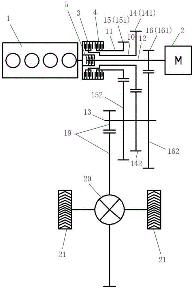
Figure 201811284479

The present invention provides a hybrid drive system and a vehicle, comprising an engine, a motor, a first clutch, a second clutch, a third clutch, a first input shaft, a second input shaft, a third input shaft, an output shaft, and a first gear group, the second gear group and the third gear group; the engine is connected with the first input shaft, the second input shaft and the third input shaft respectively through the first clutch, the second clutch and the third clutch; the first input shaft, the second input shaft The input shaft and the third input shaft are respectively connected to the output shaft through the first gear set, the second gear set and the third gear set to reduce the speed; the motor is connected with the third input shaft or the output shaft; the first gear set, the second gear set and the The third gear set corresponds to three speed ratios. The power of the engine can be selectively transmitted to the output shaft through one gear set of the first gear set, the second gear set and the third gear set, so as to realize the three-speed speed change of the engine, and the motor can generate electricity or drive to meet different driving requirements , improve the economy.

Figure 201811284479

Description

混合动力驱动系统及车辆Hybrid drive systems and vehicles

技术领域technical field

本发明属于动力技术领域,特别是涉及一种混合动力驱动系统及车辆。The invention belongs to the field of power technology, and in particular relates to a hybrid drive system and a vehicle.

背景技术Background technique

混合动力驱动系统可以通过多种方式改进车辆经济性。例如,发动机可以在怠速、减速或制动期间关闭,采用纯电驱动模式行驶,以消除由于发动机阻力导致的效率损失。另外,通过再生制动产生或由电机在发动机运行期间发电存储在动力电池中的能量,可在纯电驱动模式下被利用,或在混合驱动模式下补充发动机的转矩或功率。Hybrid drive systems can improve vehicle economy in a number of ways. For example, the engine can be shut down during idling, deceleration or braking to drive in an electric-only drive mode to eliminate efficiency losses due to engine drag. In addition, energy generated by regenerative braking or stored in the power battery by the electric machine during engine operation can be utilized in pure electric drive mode, or supplemented with engine torque or power in hybrid drive mode.

混合动力车辆能够结合至少两种不同的动力来进行驱动,目前大部分混合动力车辆都是采用油电混合动力驱动系统,该混合动力驱动系统包括从燃油得到动力的发动机和由电力驱动的电动机。为了最大程度上改善发动机的燃烧效率,很多汽车厂商开发的混合动力驱动系统都采用了双电机结构,即除驱动电机外,还增加了一个发电机。由于同时存在发动机、发电机和驱动电机,三者之间的连接和控制将直接影响混合动力车辆的性能。Hybrid vehicles can be driven by combining at least two different types of power. At present, most hybrid vehicles use a gasoline-electric hybrid drive system, which includes an engine powered by fuel and an electric motor driven by electricity. In order to improve the combustion efficiency of the engine to the greatest extent, the hybrid drive system developed by many car manufacturers adopts a dual-motor structure, that is, in addition to the drive motor, a generator is also added. Due to the simultaneous existence of the engine, generator and drive motor, the connection and control between the three will directly affect the performance of the hybrid vehicle.

现有的混合动力驱动系统,包括发动机、动力电机、副电机、第一输入轴、第二输入轴、第一输出轴和第二输出轴,发动机通过双离合器将动力输出到混合动力汽车的车轮,第二输入轴同轴地套设在第一输入轴上,发动机设置成通过双离合器可选择性地接合第一输入轴和第二输入轴中的一个,第一输入轴和第二输入轴中的每个输入轴上设置有挡位主动齿轮,第一输出轴和第二输出轴与第一输入轴平行设置,第一输出轴和第二输出轴中的每个输出轴上设置有挡位从动齿轮,挡位从动齿轮与挡位主动齿轮对应地啮合,动力电机设置成与第一输入轴或第二输入轴联动,副电机与发动机相连并在发动机的带动下进行发电以实现给动力电池充电;虽然设置了两个电机,但两个电机在功能上进行了区分,动力电机仅用于驱动,副电机仅用于发电,充电效率低,而且发动机只有两个动力输出挡位,不能有效地将混合动力驱动系统保持在高效区间工作。The existing hybrid drive system includes an engine, a power motor, an auxiliary motor, a first input shaft, a second input shaft, a first output shaft and a second output shaft, and the engine outputs power to the wheels of the hybrid vehicle through dual clutches , the second input shaft is coaxially sleeved on the first input shaft, the engine is arranged to selectively engage one of the first input shaft and the second input shaft through the dual clutch, the first input shaft and the second input shaft A gear drive gear is arranged on each input shaft in the first output shaft and the second output shaft is arranged in parallel with the first input shaft. The gear driven gear, the gear driven gear meshes with the gear driving gear correspondingly, the power motor is arranged to be linked with the first input shaft or the second input shaft, the auxiliary motor is connected with the engine and is driven by the engine to generate electricity to achieve Charge the power battery; although two motors are provided, the two motors are functionally differentiated. The power motor is only used for driving, and the auxiliary motor is only used for power generation. The charging efficiency is low, and the engine has only two power output gears. , cannot effectively keep the hybrid drive system working in the high-efficiency range.

此外,现有的混合动力驱动系统很难同时解决低速和中低速发动机效率问题、电平衡问题以及发动机高速动力性问题。发动机很难工作在燃油经济区间,车辆经济性较差。In addition, it is difficult for the existing hybrid drive system to simultaneously solve the low-speed and medium-low-speed engine efficiency problems, the electrical balance problem, and the engine high-speed dynamic problem. The engine is difficult to work in the fuel economy range, and the vehicle economy is poor.

发明内容SUMMARY OF THE INVENTION

本发明所要解决的技术问题是:针对现有方案车辆经济性较差的问题,提供一种混合动力驱动系统及车辆。The technical problem to be solved by the present invention is to provide a hybrid drive system and a vehicle for the problem of poor vehicle economy in the existing solution.

为解决上述技术问题,一方面,本发明实施例提供一种混合动力驱动系统,包括发动机、电机、第一离合器、第二离合器、第三离合器、第一输入轴、第二输入轴、第三输入轴、输出轴、第一齿轮组、第二齿轮组和第三齿轮组;In order to solve the above technical problems, on the one hand, an embodiment of the present invention provides a hybrid drive system, including an engine, a motor, a first clutch, a second clutch, a third clutch, a first input shaft, a second input shaft, a third an input shaft, an output shaft, a first gear set, a second gear set and a third gear set;

所述发动机通过所述第一离合器、所述第二离合器和所述第三离合器分别与所述第一输入轴、所述第二输入轴和所述第三输入轴相连;the engine is connected to the first input shaft, the second input shaft and the third input shaft through the first clutch, the second clutch and the third clutch, respectively;

所述第一输入轴、所述第二输入轴和所述第三输入轴分别通过所述第一齿轮组、所述第二齿轮组和所述第三齿轮组减速连接于所述输出轴;the first input shaft, the second input shaft and the third input shaft are connected to the output shaft through the first gear set, the second gear set and the third gear set, respectively;

所述电机与所述第三输入轴或所述输出轴相连;the motor is connected to the third input shaft or the output shaft;

所述第一齿轮组、所述第二齿轮组和所述第三齿轮组对应三种速比。The first gear set, the second gear set and the third gear set correspond to three speed ratios.

另一方面,本发明实施例还提供一种车辆,其包括上述的混合动力驱动系统。On the other hand, an embodiment of the present invention also provides a vehicle including the above hybrid drive system.

本发明实施例的混合动力驱动系统及车辆,通过控制第一离合器、第二离合器、第三离合器的接合或断开,发动机的动力能够选择性地通过第一齿轮组、第二齿轮组和第三齿轮组中的一个齿轮组传递动力至输出轴,从而使发动机能进行三种速比的输出,实现发动机的三挡变速,电机可用于发电或驱动,能够实现纯电驱动模式、并联驱动模式和发动机直接驱动模式,且其中多种驱动模式具有多个挡位,可以满足不同驱动力要求,尽可能地使发动机工作在具有较高燃油经济性的区间、使电机工作在具有较高经济性的区间,解决了低速、中速时发动机效率问题和电平衡问题以及高速时发动机动力性问题,系统工作效率高,以此提高车辆经济性;该混合动力驱动系统,结构简单、紧凑,使用的零部件数量较少,降低了混合动力驱动系统的结构复杂程度,能量传递损失较少,提高了系统效率。In the hybrid drive system and the vehicle according to the embodiments of the present invention, by controlling the engagement or disconnection of the first clutch, the second clutch and the third clutch, the power of the engine can selectively pass through the first gear set, the second gear set and the third clutch. One gear set in the three gear sets transmits power to the output shaft, so that the engine can output three speed ratios to realize the three-speed speed change of the engine. The motor can be used for power generation or driving, and can realize pure electric drive mode and parallel drive mode. And engine direct drive mode, and many of the drive modes have multiple gears, which can meet different driving force requirements, try to make the engine work in the range with higher fuel economy, and make the motor work in a higher economy. It solves the problem of engine efficiency and electrical balance at low and medium speed, and the problem of engine power at high speed, and the system has high working efficiency, thereby improving vehicle economy; the hybrid drive system has a simple and compact structure and uses The number of components is less, the structural complexity of the hybrid drive system is reduced, the energy transmission loss is less, and the system efficiency is improved.

附图说明Description of drawings

图1为本发明提供的混合动力驱动系统的结构简图一;1 is a schematic structural diagram 1 of a hybrid drive system provided by the present invention;

图2为本发明提供的混合动力驱动系统的结构简图二;FIG. 2 is a schematic structural diagram 2 of the hybrid drive system provided by the present invention;

图3为本发明提供的混合动力驱动系统的结构简图三;FIG. 3 is a schematic structural diagram 3 of the hybrid drive system provided by the present invention;

图4为本发明提供的混合动力驱动系统的结构简图四;FIG. 4 is a schematic diagram 4 of the structure of the hybrid drive system provided by the present invention;

图5为本发明提供的混合动力驱动系统的结构简图五;FIG. 5 is a schematic structural diagram 5 of the hybrid drive system provided by the present invention;

图6为本发明提供的混合动力驱动系统的结构简图六;FIG. 6 is a schematic structural diagram 6 of the hybrid drive system provided by the present invention;

图7为本发明提供的混合动力驱动系统的结构简图七;FIG. 7 is a schematic diagram 7 of the structure of the hybrid drive system provided by the present invention;

图8为本发明提供的混合动力驱动系统的结构简图八;FIG. 8 is a schematic structural diagram 8 of the hybrid drive system provided by the present invention;

图9为本发明提供的混合动力驱动系统的结构简图九;FIG. 9 is a schematic structural diagram 9 of the hybrid drive system provided by the present invention;

图10为本发明提供的混合动力驱动系统的结构简图十;FIG. 10 is a schematic structural diagram ten of the hybrid drive system provided by the present invention;

图11为本发明提供的混合动力驱动系统的结构简图十一;FIG. 11 is a schematic structural diagram eleven of the hybrid drive system provided by the present invention;

图12为本发明提供的混合动力驱动系统的结构简图十二;FIG. 12 is a schematic structural diagram 12 of the hybrid drive system provided by the present invention;

图13为本发明提供的混合动力驱动系统的结构简图十三;FIG. 13 is a schematic structural diagram thirteen of the hybrid drive system provided by the present invention;

图14为本发明提供的混合动力驱动系统的结构简图十四;FIG. 14 is a schematic diagram fourteen of the structure of the hybrid drive system provided by the present invention;

图15为图1所示的混合动力驱动系统的局部在纯电动驱动模式下的动力传递路线图;FIG. 15 is a partial power transmission road map of the hybrid drive system shown in FIG. 1 in a pure electric drive mode;

图16为图1所示的混合动力驱动系统的局部在第一并联驱动模式下的动力传递路线图;FIG. 16 is a partial power transmission route diagram of the hybrid drive system shown in FIG. 1 in the first parallel drive mode;

图17为图1所示的混合动力驱动系统的局部在第二并联驱动模式下的动力传递路线图;FIG. 17 is a partial power transmission route diagram of the hybrid drive system shown in FIG. 1 in the second parallel drive mode;

图18为图1所示的混合动力驱动系统的局部在第三并联驱动模式下的动力传递路线图;FIG. 18 is a partial power transmission road map of the hybrid drive system shown in FIG. 1 in a third parallel drive mode;

图19为图1所示的混合动力驱动系统的局部在第一发动机直接驱动模式下的动力传递路线图;FIG. 19 is a partial power transmission road map of the hybrid drive system shown in FIG. 1 in the first engine direct drive mode;

图20为图1所示的混合动力驱动系统的局部在第二发动机直接驱动模式下的动力传递路线图;FIG. 20 is a partial power transmission road map of the hybrid drive system shown in FIG. 1 in the second engine direct drive mode;

图21为图1所示的混合动力驱动系统的局部在第三发动机直接驱动模式下的动力传递路线图;FIG. 21 is a partial power transmission road map of the hybrid drive system shown in FIG. 1 in the third engine direct drive mode;

图22为图1所示的混合动力驱动系统的局部在第四发动机直接驱动模式下的动力传递路线图;FIG. 22 is a power transmission route diagram of a part of the hybrid drive system shown in FIG. 1 in the fourth engine direct drive mode;

图23为图1所示的混合动力驱动系统的局部在第五发动机直接驱动模式下的动力传递路线图;FIG. 23 is a partial power transmission road map of the hybrid drive system shown in FIG. 1 in the fifth engine direct drive mode;

图24为图1所示的混合动力驱动系统的局部在第六发动机直接驱动模式下的动力传递路线图;FIG. 24 is a partial power transmission road map of the hybrid drive system shown in FIG. 1 in the sixth engine direct drive mode;

图25为本发明提供的车辆的结构简图。FIG. 25 is a schematic structural diagram of a vehicle provided by the present invention.

说明书中的附图标记如下:The reference numbers in the description are as follows:

1、发动机;2、电机;3、第一离合器;4、第二离合器;5、第三离合器;6、第四离合器;7、制动器;1, engine; 2, motor; 3, first clutch; 4, second clutch; 5, third clutch; 6, fourth clutch; 7, brake;

8、行星齿轮机构;801、太阳轮;802、行星架;803、齿圈;804、行星轮;8. Planetary gear mechanism; 801, sun gear; 802, planet carrier; 803, ring gear; 804, planetary gear;

9、同步器;10、第一输入轴;11、第二输入轴;12、第三输入轴;9. Synchronizer; 10. First input shaft; 11. Second input shaft; 12. Third input shaft;

13、输出轴;131、第一轴段;132、第二轴段;13, output shaft; 131, first shaft segment; 132, second shaft segment;

14、第一齿轮组;141、第一主动齿轮;142、第一从动齿轮;14. The first gear set; 141. The first driving gear; 142. The first driven gear;

15、第二齿轮组;151、第二主动齿轮;152、第二从动齿轮;15. The second gear set; 151, the second driving gear; 152, the second driven gear;

16、第三齿轮组;161、第三主动齿轮;162、第三从动齿轮;16, the third gear set; 161, the third driving gear; 162, the third driven gear;

17、第四齿轮组;171、第四主动齿轮;172、第四从动齿轮;17. The fourth gear set; 171, the fourth driving gear; 172, the fourth driven gear;

18、第五齿轮组;181、第五主动齿轮;182、第五从动齿轮;18. The fifth gear set; 181, the fifth driving gear; 182, the fifth driven gear;

19、主减速器;20、差速器;21、车轮;19. Final gear; 20. Differential; 21. Wheels;

100、车辆;200、混合动力驱动系统。100. Vehicle; 200. Hybrid drive system.

具体实施方式Detailed ways

为了使本发明所解决的技术问题、技术方案及有益效果更加清楚明白,以下结合附图及实施例,对本发明进行进一步的详细说明。应当理解,此处所描述的具体实施例仅仅用以解释本发明,并不用于限定本发明。In order to make the technical problems, technical solutions and beneficial effects solved by the present invention clearer, the present invention will be further described in detail below with reference to the accompanying drawings and embodiments. It should be understood that the specific embodiments described herein are only used to explain the present invention, but not to limit the present invention.

第一实施例first embodiment

请参阅图1和图3,本发明第一实施例提供的一种动力驱动系统,包括发动机1、电机2、第一离合器3、第二离合器4、第三离合器5、第一输入轴10、第二输入轴11、第三输入轴12、输出轴13、第一齿轮组14、第二齿轮组15和第三齿轮组16;Referring to FIGS. 1 and 3 , a power drive system provided by the first embodiment of the present invention includes an engine 1, a motor 2, a first clutch 3, a second clutch 4, a third clutch 5, a first input shaft 10, the second input shaft 11, the third input shaft 12, the output shaft 13, the first gear set 14, the second gear set 15 and the third gear set 16;

发动机1通过第一离合器3、第二离合器4和第三离合器5分别与第一输入轴10、第二输入轴11和第三输入轴12相连;The engine 1 is connected with the first input shaft 10, the second input shaft 11 and the third input shaft 12 through the first clutch 3, the second clutch 4 and the third clutch 5, respectively;

第一输入轴10、第二输入轴11和第三输入轴12分别通过第一齿轮组14、第二齿轮组15和第三齿轮组16减速连接于输出轴13;The first input shaft 10 , the second input shaft 11 and the third input shaft 12 are respectively connected to the output shaft 13 through the first gear set 14 , the second gear set 15 and the third gear set 16 to reduce speed;

电机2与第三输入轴12或输出轴13相连;The motor 2 is connected to the third input shaft 12 or the output shaft 13;

第一齿轮组14、第二齿轮组15和第三齿轮组16对应三种速比。The first gear set 14 , the second gear set 15 and the third gear set 16 correspond to three speed ratios.

通过控制第一离合器3、第二离合器4、第三离合器5的接合或断开,发动机1的动力能够选择性地通过第一齿轮组14、第二齿轮组15和第三齿轮组16中的一个齿轮组传递动力至输出轴13,从而使发动机1能进行三种速比的输出,实现发动机1的三挡变速,电机2可用于发电或驱动,能够实现纯电驱动模式、并联驱动模式和发动机直接驱动模式,且其中多种驱动模式具有多个挡位,可以满足不同驱动力要求,尽可能地使发动机1工作在具有较高燃油经济性的区间、使电机2工作在具有较高经济性的区间,解决了低速、中速时发动机1效率问题和电平衡问题以及高速时发动机1动力性问题,系统工作效率高,以此提高车辆经济性;该混合动力驱动系统,结构简单、紧凑,使用的零部件数量较少,降低了混合动力驱动系统的结构复杂程度,能量传递损失较少,提高了系统效率。By controlling the engagement or disengagement of the first clutch 3 , the second clutch 4 , and the third clutch 5 , the power of the engine 1 can be selectively passed through the first gear set 14 , the second gear set 15 and the third gear set 16 . A gear set transmits power to the output shaft 13, so that the engine 1 can output three speed ratios, realize the three-speed speed change of the engine 1, and the motor 2 can be used for power generation or driving, and can realize the pure electric drive mode, parallel drive mode and The engine direct drive mode, and many of the drive modes have multiple gears, which can meet different driving force requirements, and make the engine 1 work in the range with higher fuel economy as much as possible, and make the motor 2 work in the region with higher fuel economy. It solves the problem of engine 1 efficiency and electrical balance at low and medium speeds and the power problem of engine 1 at high speed, and the system has high working efficiency, thereby improving vehicle economy; the hybrid drive system has a simple and compact structure. , the number of components used is less, the structural complexity of the hybrid drive system is reduced, the energy transmission loss is less, and the system efficiency is improved.

此外,请参阅图1,该混合动力驱动系统还包括主减速器19和差速器20,主减速器19连接在输出轴13的输出端,差速器20连接于主减速器19与车轮21之间,以此将输出轴13的动力通过主减速器19和差速器20传递至车轮21,驱动车辆行驶。当然,输出轴13与主减速器19之间还可设置用于传递动力的输出构件。In addition, referring to FIG. 1 , the hybrid drive system further includes a final gear 19 and a differential gear 20 , the final gear 19 is connected to the output end of the output shaft 13 , and the differential gear 20 is connected to the final gear 19 and the wheels 21 . In between, the power of the output shaft 13 is transmitted to the wheels 21 through the final reducer 19 and the differential gear 20 to drive the vehicle. Of course, an output member for transmitting power may also be provided between the output shaft 13 and the final reducer 19 .

优选地,请参阅图1,第一齿轮组14包括设于第一输入轴10上的第一主动齿轮141和设于输出轴13上的第一从动齿轮142,第一主动齿轮141与第一从动齿轮142啮合;Preferably, please refer to FIG. 1 , the first gear set 14 includes a first driving gear 141 arranged on the first input shaft 10 and a first driven gear 142 arranged on the output shaft 13 . A driven gear 142 meshes;

第二齿轮组15包括设于第二输入轴11上的第二主动齿轮151和设于输出轴13上的第二从动齿轮152,第二主动齿轮151与第二从动齿轮152啮合;The second gear set 15 includes a second driving gear 151 arranged on the second input shaft 11 and a second driven gear 152 arranged on the output shaft 13, and the second driving gear 151 meshes with the second driven gear 152;

第三齿轮组16包括设于第三输入轴12上的第三主动齿轮161和设于输出轴13上的第三从动齿轮162,第三主动齿轮161与第三从动齿轮162啮合;简化了动力输出路径,结构更为简单、紧凑,有利于减少能量传递损失及动力驱动系统的小型化。The third gear set 16 includes a third driving gear 161 provided on the third input shaft 12 and a third driven gear 162 provided on the output shaft 13. The third driving gear 161 meshes with the third driven gear 162; simplified The power output path is eliminated, the structure is simpler and more compact, and the power transmission loss is reduced and the power drive system is miniaturized.

优选地,请参阅图5,当电机2与输出轴13相连时,混合动力驱动系统还包括第四输入轴和第四齿轮组17,电机2与第四输入轴相连,第四输入轴通过第四齿轮组17连接于输出轴13;能够实现电机2到输出轴13的减速增流及输出轴13到电机2的增速降流。Preferably, referring to FIG. 5, when the motor 2 is connected to the output shaft 13, the hybrid drive system further includes a fourth input shaft and a fourth gear set 17, the motor 2 is connected to the fourth input shaft, and the fourth input shaft passes through the fourth input shaft. The four-gear set 17 is connected to the output shaft 13;

更优选地,请参阅图5,第四齿轮组17包括设于第四输入轴上的第四主动齿轮171和设于输出轴13上的第四从动齿轮172;结构简单、紧凑,有利于减少能量传递损失及动力驱动系统的小型化。More preferably, referring to FIG. 5, the fourth gear set 17 includes a fourth driving gear 171 arranged on the fourth input shaft and a fourth driven gear 172 arranged on the output shaft 13; the structure is simple and compact, which is beneficial to Reduce energy transmission loss and miniaturization of power drive system.

当然,电机2也可通过其它减速结构减速连接输出轴13,如行星齿轮机构8。Of course, the motor 2 can also be connected to the output shaft 13 through other deceleration structures, such as the planetary gear mechanism 8 .

优选地,当电机2与第三输入轴12相连时,混合动力驱动系统还包括增速齿轮组,第三输入轴12通过增速齿轮组增速连接电机2;能够实现第三输入轴12到电机2的增速降流及电机2到第三输入轴12的减速增流。Preferably, when the motor 2 is connected to the third input shaft 12, the hybrid drive system further includes a speed-increasing gear set, and the third input shaft 12 is connected to the motor 2 through the speed-increasing gear set; The speed-up and down-current of the motor 2 and the deceleration and current-increase of the motor 2 to the third input shaft 12 .

优选地,请参阅图1,第一离合器3、第二离合器4和第三离合器5为集成式三离合器,第一输入轴10和第二输入轴11均为空心轴,第一输入轴10可转动地设于第二输入轴11的轴孔内,第三输入轴12可转动地设于第一输入轴10的轴孔内。结构简单、紧凑,有利于混合动力驱动系统的小型化,尽量减少能量传递损失。Preferably, referring to FIG. 1 , the first clutch 3 , the second clutch 4 and the third clutch 5 are integrated three-clutches, the first input shaft 10 and the second input shaft 11 are hollow shafts, and the first input shaft 10 can be The third input shaft 12 is rotatably arranged in the shaft hole of the first input shaft 10 and is rotatably arranged in the shaft hole of the second input shaft 11 . The structure is simple and compact, which is beneficial to the miniaturization of the hybrid drive system and minimizes the loss of energy transmission.

更优选地,第一离合器3、第二离合器4和第三离合器5同轴固设;第三离合器5嵌于第一离合器3和第二离合器4内(请参阅图1),或者第一离合器3和第三离合器5嵌于第二离合器4内(未图示)。实现第一离合器3、第二离合器4和第三离合器5的集成,输入轴中位于最中心的第三输入轴12对应的第三离合器5设于集成式三离合器的内层,输入轴中位于最外层的第二输入轴11对应的第二离合器4设于集成式三离合器中的外层,输入轴中居中的第一输入轴10对应的第一离合器3设于集成式三离合器中的内层或外层,结构简单、紧凑,有利于集成式三离合器的小型化,还可适用于较短的输入轴(较第一离合器3、第二离合器4和第三离合器5排成一行设置时),有利于减小负载。More preferably, the first clutch 3, the second clutch 4 and the third clutch 5 are fixed coaxially; the third clutch 5 is embedded in the first clutch 3 and the second clutch 4 (refer to FIG. 1), or the first clutch 3 and the third clutch 5 are fitted into the second clutch 4 (not shown). The integration of the first clutch 3, the second clutch 4 and the third clutch 5 is realized. The third clutch 5 corresponding to the third input shaft 12 located at the center of the input shaft is arranged in the inner layer of the integrated three-clutch, and the input shaft is located in the inner layer of the integrated three-clutch. The second clutch 4 corresponding to the outermost second input shaft 11 is provided in the outer layer of the integrated three-clutch, and the first clutch 3 corresponding to the first input shaft 10 in the center of the input shaft is provided in the integrated three-clutch. The inner or outer layer has a simple and compact structure, which is conducive to the miniaturization of the integrated three-clutch, and can also be applied to a shorter input shaft (compared with the first clutch 3, the second clutch 4 and the third clutch 5 arranged in a row). time), which is beneficial to reduce the load.

更优选地,第一离合器3的从动部分较主动部分更靠近发动机1的轴线,第二离合器4的从动部分较主动部分更靠近发动机1的轴线,第二离合器4的从动部分较主动部分更靠近发动机1的轴线,有利于减小第一输入轴10、第二输入轴11和第三输入轴12的尺寸,从而减小负载。More preferably, the driven part of the first clutch 3 is closer to the axis of the engine 1 than the driving part, the driven part of the second clutch 4 is closer to the axis of the engine 1 than the driving part, and the driven part of the second clutch 4 is more active. The parts are closer to the axis of the engine 1, which is beneficial to reduce the size of the first input shaft 10, the second input shaft 11 and the third input shaft 12, thereby reducing the load.

第一实施例提供的混合动力驱动系统具有以下多种驱动模式:纯电驱动模式、3个并联驱动模式(第一并联驱动模式、第二并联驱动模式和第三并联驱动模式)、6个发动机直接驱动模式(第一发动机直接驱动模式、第二发动机直接驱动模式、第三发动机直接驱动模式、第四发动机直接驱动模式、第五发动机直接驱动模式和第六发动机直接驱动模式)。各个驱动模式下的操作逻辑如表1所示,第一齿轮组14、第二齿轮组15和第三齿轮组16在表1和图15-24中还分别用GS1、GS2和GS3表示。The hybrid drive system provided by the first embodiment has the following multiple drive modes: pure electric drive mode, 3 parallel drive modes (first parallel drive mode, second parallel drive mode and third parallel drive mode), 6 engines Direct drive modes (first engine direct drive mode, second engine direct drive mode, third engine direct drive mode, fourth engine direct drive mode, fifth engine direct drive mode, and sixth engine direct drive mode). The operation logic in each driving mode is shown in Table 1, and the first gear set 14, the second gear set 15 and the third gear set 16 are also represented by GS1, GS2 and GS3 in Table 1 and FIGS. 15-24, respectively.

表1各驱动模式下的操作逻辑表(第一实施例)Table 1 Operation logic table in each driving mode (first embodiment)

驱动模式drive mode 第一离合器first clutch 第二离合器second clutch 第三离合器third clutch 发动机engine 电机motor 纯电驱动Pure electric drive 断开disconnect 断开disconnect 断开disconnect 不工作Not working 驱动drive 第一并联驱动first parallel drive 接合engage 断开disconnect 断开disconnect 驱动drive 驱动drive 第二并联驱动second parallel drive 断开disconnect 接合engage 断开disconnect 驱动drive 驱动drive 第三并联驱动third parallel drive 断开disconnect 断开disconnect 接合engage 驱动drive 驱动drive 第一发动机直接驱动first engine direct drive 接合engage 断开disconnect 断开disconnect 驱动drive 发电power generation 第二发动机直接驱动second engine direct drive 断开disconnect 接合engage 断开disconnect 驱动drive 发电power generation 第三发动机直接驱动third engine direct drive 断开disconnect 断开disconnect 接合engage 驱动drive 发电power generation 第四发动机直接驱动Fourth engine direct drive 接合engage 断开disconnect 断开disconnect 驱动drive 不工作Not working 第五发动机直接驱动Fifth engine direct drive 断开disconnect 接合engage 断开disconnect 驱动drive 不工作Not working 第六发动机直接驱动sixth engine direct drive 断开disconnect 断开disconnect 接合engage 驱动drive 不工作Not working

以下详细说明各个驱动模式下的动力传递路线。The power transmission route in each drive mode will be described in detail below.

当电机2与第三输入轴12相连时(请参阅图1):从电机2到输出轴13的动力路线为:电机2-〉第三输入轴12-〉第三齿轮组16-〉输出轴13,从输出轴13到电机2的动力路线为:输出轴13-〉第三齿轮组16-〉第三输入轴12-〉电机2;进一步地,若还设有增速齿轮组,则从电机2到第三输入轴12的路线为:电机2-〉增速齿轮组-〉第三输入轴12,从第三输入轴12到电机2的路线为:第三输入轴12-〉增速齿轮组-〉电机2;When the motor 2 is connected to the third input shaft 12 (please refer to Figure 1): the power path from the motor 2 to the output shaft 13 is: motor 2 -> the third input shaft 12 -> the third gear set 16 -> the output shaft 13. The power route from the output shaft 13 to the motor 2 is: the output shaft 13->the third gear set 16->the third input shaft 12->the motor 2; The route from the motor 2 to the third input shaft 12 is: motor 2 -> the speed-increasing gear set -> the third input shaft 12, and the route from the third input shaft 12 to the motor 2 is: the third input shaft 12 -> the speed-increasing Gear set -> Motor 2;

当电机2与输出轴13相连时(请参阅图3和图5):从电机2到输出轴13的动力路线为:电机2-〉输出轴13,从输出轴13到电机2的动力路线为:输出轴13-〉电机2;进一步地,若还设有第四齿轮组17(请参阅图5),则从电机2到输出轴13的路线为:电机2-〉第四输入轴-〉第四齿轮组17-〉输出轴13,从输出轴13到电机2的路线为:输出轴13-〉第四齿轮组17-〉第四输入轴-〉电机2;When the motor 2 is connected to the output shaft 13 (refer to Figure 3 and Figure 5): the power path from the motor 2 to the output shaft 13 is: motor 2 -> the output shaft 13, and the power path from the output shaft 13 to the motor 2 is : output shaft 13 -> motor 2; further, if there is also a fourth gear set 17 (see Figure 5), the route from motor 2 to output shaft 13 is: motor 2 -> fourth input shaft -> Fourth gear set 17 -> output shaft 13, the route from output shaft 13 to motor 2 is: output shaft 13 -> fourth gear set 17 -> fourth input shaft -> motor 2;

为简化第一实施例的下述各模式的动力传递路线的表述,动力传递路线表述中均省略从电机2到输出轴13及从输出轴13到电机2的具体路径。In order to simplify the description of the power transmission routes of the following modes of the first embodiment, the specific paths from the motor 2 to the output shaft 13 and from the output shaft 13 to the motor 2 are omitted in the description of the power transmission routes.

(1)纯电驱动模式(1) Pure electric drive mode

断开第一离合器3、第二离合器4和第三离合器5,发动机1不工作,电机2驱动,以建立纯电驱动模式;Disconnect the first clutch 3, the second clutch 4 and the third clutch 5, the engine 1 does not work, and the motor 2 is driven to establish a pure electric drive mode;

请参阅图15,该驱动模式下的动力传递路线为:电机2-〉输出轴13输出。Please refer to Figure 15, the power transmission route in this driving mode is: motor 2 -> output shaft 13 output.

在纯电驱动模式下:动力驱动系统利用电机2驱动车轮21,同时发动机1不工作,实现电机2的一挡速比输出。In the pure electric drive mode: the power drive system uses the motor 2 to drive the wheels 21 while the engine 1 does not work, so that the first gear ratio output of the motor 2 is realized.

(9)第一并联驱动模式(9) The first parallel drive mode

接合第一离合器3,断开第二离合器4和第三离合器5,发动机1驱动,电机2驱动,以建立第一并联驱动模式;The first clutch 3 is engaged, the second clutch 4 and the third clutch 5 are disconnected, the engine 1 is driven, and the motor 2 is driven to establish the first parallel driving mode;

请参阅图16,该驱动模式下的动力传递路线1为:发动机1-〉第一离合器3-〉第一输入轴10-〉第一齿轮组14-〉输出轴13输出;Please refer to FIG. 16 , the power transmission route 1 in this driving mode is: engine 1 -> first clutch 3 -> first input shaft 10 -> first gear set 14 -> output shaft 13 output;

动力传递路线2为:电机2-〉输出轴13输出。Power transmission route 2 is: motor 2 -> output shaft 13 output.

(10)第二并联驱动模式(10) The second parallel drive mode

接合第二离合器4,断开第一离合器3和第三离合器5,发动机1驱动,电机2驱动,以建立第二并联驱动模式;The second clutch 4 is engaged, the first clutch 3 and the third clutch 5 are disconnected, the engine 1 is driven, and the motor 2 is driven to establish the second parallel driving mode;

请参阅图17,该驱动模式下的动力传递路线1为:发动机1-〉第二离合器4-〉第二输入轴11-〉第二齿轮组15-〉输出轴13输出;Please refer to FIG. 17 , the power transmission route 1 in this driving mode is: engine 1 -> second clutch 4 -> second input shaft 11 -> second gear set 15 -> output shaft 13 output;

动力传递路线2为:电机2-〉输出轴13输出。Power transmission route 2 is: motor 2 -> output shaft 13 output.

(11)第三并联驱动模式(11) The third parallel drive mode

接合第三离合器5,断开第一离合器3和第二离合器4,发动机1驱动,电机2驱动,以建立第三并联驱动模式;The third clutch 5 is engaged, the first clutch 3 and the second clutch 4 are disconnected, the engine 1 is driven, and the motor 2 is driven to establish the third parallel driving mode;

请参阅图18,该驱动模式下的动力传递路线1为:发动机1-〉第三离合器5-〉第三输入轴12-〉第三齿轮组16-〉输出轴13输出;Please refer to Fig. 18, the power transmission route 1 in this driving mode is: engine 1 -> third clutch 5 -> third input shaft 12 -> third gear set 16 -> output shaft 13 output;

动力传递路线2为:电机2-〉输出轴13输出。Power transmission route 2 is: motor 2 -> output shaft 13 output.

在第一并联驱动模式、第二并联驱动模式和第三并联驱动模式下:动力驱动系统利用发动机1和电机2共同驱动,通过切换第一离合器3、第二离合器4、第三离合器5,实现发动机1的三挡速比输出。In the first parallel drive mode, the second parallel drive mode and the third parallel drive mode: the power drive system is jointly driven by the engine 1 and the motor 2, and by switching the first clutch 3, the second clutch 4, and the third clutch 5, to achieve The third gear ratio output of engine 1.

(12)第一发动机直接驱动模式(电机2发电)(12) The first engine direct drive mode (electric motor 2 generates electricity)

接合第一离合器3,断开第二离合器4和第三离合器5,发动机1驱动,电机2发电,以建立第一发动机直接驱动模式;The first clutch 3 is engaged, the second clutch 4 and the third clutch 5 are disconnected, the engine 1 is driven, and the motor 2 generates electricity to establish the first engine direct drive mode;

请参阅图19,该驱动模式下的动力传递路线1为:发动机1-〉第一离合器3-〉第一输入轴10-〉第一齿轮组14或第五齿轮组18-〉输出轴13输出;Please refer to FIG. 19 , the power transmission route 1 in this driving mode is: engine 1 -> first clutch 3 -> first input shaft 10 -> first gear set 14 or fifth gear set 18 -> output shaft 13 output ;

动力传递路线2为:发动机1-〉第一离合器3-〉第一输入轴10-〉第一齿轮组14-〉输出轴13-〉电机2。The power transmission route 2 is: engine 1 -> first clutch 3 -> first input shaft 10 -> first gear set 14 -> output shaft 13 -> motor 2 .

(13)第二发动机直接驱动模式(电机2发电)(13) The second engine direct drive mode (electric motor 2 generates electricity)

接合第二离合器4,断开第一离合器3和第三离合器5,发动机1驱动,电机2发电,以建立第二发动机直接驱动模式;The second clutch 4 is engaged, the first clutch 3 and the third clutch 5 are disconnected, the engine 1 is driven, and the motor 2 generates electricity to establish the second engine direct drive mode;

请参阅图20,该驱动模式下的动力传递路线1为:发动机1-〉第二离合器4-〉第二输入轴11-〉第二齿轮组15-〉输出轴13输出;Please refer to FIG. 20 , the power transmission route 1 in this driving mode is: engine 1 -> second clutch 4 -> second input shaft 11 -> second gear set 15 -> output shaft 13 output;

动力传递路线2为:发动机1-〉第二离合器4-〉第二输入轴11-〉第二齿轮组15-〉输出轴13-〉电机2。The power transmission route 2 is: engine 1 -> second clutch 4 -> second input shaft 11 -> second gear set 15 -> output shaft 13 -> motor 2.

(14)第三发动机直接驱动模式(电机2发电)(14) The third engine direct drive mode (electric motor 2 generates electricity)

接合第三离合器5,断开第一离合器3和第二离合器4,发动机1驱动,电机2发电,以建立第三发动机直接驱动模式;The third clutch 5 is engaged, the first clutch 3 and the second clutch 4 are disconnected, the engine 1 is driven, and the motor 2 generates electricity to establish the third engine direct drive mode;

请参阅图21,该驱动模式下的动力传递路线1为:发动机1-〉第三离合器5-〉第三输入轴12-〉第三齿轮组16-〉输出轴13输出;Please refer to Fig. 21, the power transmission route 1 in this driving mode is: engine 1 -> third clutch 5 -> third input shaft 12 -> third gear set 16 -> output shaft 13 output;

动力传递路线2为:发动机1-〉第三离合器5-〉第三输入轴12-〉电机2。The power transmission route 2 is: engine 1 -> third clutch 5 -> third input shaft 12 -> motor 2.

在第一发动机直接驱动模式、第二发动机直接驱动模式和第三发动机直接驱动模式下:动力驱动系统利用发动机1驱动,同时发动机1驱动电机2为电池发电,通过切换第一离合器3、第二离合器4、第三离合器5、同步器9,实现发动机1的三挡速比输出。In the first engine direct drive mode, the second engine direct drive mode and the third engine direct drive mode: the power drive system is driven by the engine 1, while the engine 1 drives the motor 2 to generate electricity for the battery, by switching the first clutch 3, the second The clutch 4 , the third clutch 5 and the synchronizer 9 realize the output of the third gear ratio of the engine 1 .

(15)第四发动机直接驱动模式(电机2空载)(15) Fourth engine direct drive mode (motor 2 no-load)

接合第一离合器3,断开第二离合器4和第三离合器5,发动机1驱动,电机2不工作,以建立第四发动机直接驱动模式;The first clutch 3 is engaged, the second clutch 4 and the third clutch 5 are disconnected, the engine 1 is driven, and the motor 2 does not work, so as to establish the fourth engine direct drive mode;

请参阅图22,该驱动模式下的动力传递路线为:发动机1-〉第一离合器3-〉第一输入轴10-〉第一齿轮组14或第五齿轮组18-〉输出轴13输出。Please refer to FIG. 22 , the power transmission route in this driving mode is: engine 1 -> first clutch 3 -> first input shaft 10 -> first gear set 14 or fifth gear set 18 -> output shaft 13 output.

(16)第五发动机直接驱动模式(电机2空载)(16) Fifth engine direct drive mode (motor 2 no-load)

接合第二离合器4,断开第一离合器3和第三离合器5,发动机1驱动,电机2不工作,以建立第五发动机直接驱动模式;The second clutch 4 is engaged, the first clutch 3 and the third clutch 5 are disconnected, the engine 1 is driven, and the motor 2 does not work, so as to establish the fifth engine direct drive mode;

请参阅图23,该驱动模式下的动力传递路线为:发动机1-〉第二离合器4-〉第二输入轴11-〉第二齿轮组15-〉输出轴13输出。Please refer to FIG. 23 , the power transmission route in this driving mode is: engine 1 -> second clutch 4 -> second input shaft 11 -> second gear set 15 -> output shaft 13 output.

(17)第六发动机直接驱动模式(电机2空载)(17) Sixth engine direct drive mode (motor 2 no-load)

接合第三离合器5,断开第一离合器3和第二离合器4,发动机1驱动,电机2不工作,以建立第六发动机直接驱动模式;The third clutch 5 is engaged, the first clutch 3 and the second clutch 4 are disconnected, the engine 1 is driven, and the motor 2 does not work, so as to establish the sixth engine direct drive mode;

请参阅图24,该驱动模式下的动力传递路线为:发动机1-〉第三离合器5-〉第三输入轴12-〉第三齿轮组16-〉输出轴13输出。Referring to Figure 24, the power transmission route in this driving mode is: engine 1 -> third clutch 5 -> third input shaft 12 -> third gear set 16 -> output shaft 13 output.

在第四发动机直接驱动模式、第五发动机直接驱动模式和第六发动机直接驱动模式下:动力驱动系统利用发动机1驱动,同时电机2不工作,通过切换第一离合器3、第二离合器4、第三离合器5、同步器9,实现发动机1的三挡速比输出。In the fourth engine direct drive mode, the fifth engine direct drive mode and the sixth engine direct drive mode: the power drive system is driven by the engine 1, while the motor 2 does not work, by switching the first clutch 3, the second clutch 4, the first clutch The three clutches 5 and the synchronizer 9 realize the output of the third gear ratio of the engine 1 .

第二实施例Second Embodiment

本实施例在第一实施例的基础上增设了第四离合器6。其中:In this embodiment, a fourth clutch 6 is added on the basis of the first embodiment. in:

当电机2与第三输入轴12相连时,电机2通过第四离合器6与第三输入轴12相连(请参阅图2);When the motor 2 is connected to the third input shaft 12, the motor 2 is connected to the third input shaft 12 through the fourth clutch 6 (refer to FIG. 2);

若第四离合器6接合:从电机2到第三输入轴12的动力传递路线为:电机2-〉第四离合器6-〉第三输入轴12,从第三输入轴12到电机2的动力传递路线为:第三输入轴12-〉第四离合器6-〉电机2;进一步地,若还设有增速齿轮组,则从电机2到第三输入轴12的路线为:电机2-〉第四离合器6-〉增速齿轮组-〉第三输入轴12,从第三输入轴12到电机2的路线为:第三输入轴12-〉增速齿轮组-〉第四离合器6-〉电机2;If the fourth clutch 6 is engaged: the power transmission route from the motor 2 to the third input shaft 12 is: motor 2 -> the fourth clutch 6 -> the third input shaft 12, the power transmission from the third input shaft 12 to the motor 2 The route is: the third input shaft 12 -> the fourth clutch 6 -> the motor 2; further, if a speed-increasing gear set is also provided, the route from the motor 2 to the third input shaft 12 is: the motor 2 -> the first Four clutches 6 -> speed increasing gear set -> third input shaft 12, the route from third input shaft 12 to motor 2 is: third input shaft 12 -> speed increasing gear set -> fourth clutch 6 -> motor 2;

当电机2与输出轴13相连时,电机2通过第四离合器6与输出轴13相连(请参阅图4);When the motor 2 is connected to the output shaft 13, the motor 2 is connected to the output shaft 13 through the fourth clutch 6 (refer to FIG. 4);

若第四离合器6接合:从电机2到输出轴13的动力传递路线为:电机2-〉第四离合器6-〉输出轴13,从输出轴13到电机2的动力传递路线为:输出轴13-〉第四离合器6-〉电机2;If the fourth clutch 6 is engaged: the power transmission route from the motor 2 to the output shaft 13 is: motor 2 -> the fourth clutch 6 -> the output shaft 13, and the power transmission route from the output shaft 13 to the motor 2 is: the output shaft 13 -> Fourth clutch 6 -> Motor 2;

当电机2通过第四输入轴和第四齿轮组17与输出轴13相连时,电机2通过第四离合器6与第四输入轴相连(请参阅图6);When the motor 2 is connected with the output shaft 13 through the fourth input shaft and the fourth gear set 17, the motor 2 is connected with the fourth input shaft through the fourth clutch 6 (please refer to FIG. 6 );

若第四离合器6接合:从电机2到第四输入轴的动力传递路线为:电机2-〉第四离合器6-〉第四输入轴,从第四输入轴到电机2的动力传递路线为:第四输入轴-〉第四离合器6-〉电机2。第二实施例的其它结构与第一实施例相同,此处不再赘述。If the fourth clutch 6 is engaged: the power transmission route from the motor 2 to the fourth input shaft is: motor 2 -> the fourth clutch 6 -> the fourth input shaft, and the power transmission route from the fourth input shaft to the motor 2 is: Fourth input shaft -> fourth clutch 6 -> motor 2. Other structures of the second embodiment are the same as those of the first embodiment, and will not be repeated here.

需要电机2发电或驱动时,接合第四离合器6,即可实现电机2接入驱动、发电线路;无需电机2驱动或发电时,断开第四离合器6即可实现电机2与驱动线路的断开,减小负载,提高燃油经济性。When the motor 2 is required to generate or drive, the fourth clutch 6 can be engaged, and the motor 2 can be connected to the drive and power generation circuits; when the motor 2 is not required to drive or generate electricity, the fourth clutch 6 can be disconnected to realize the disconnection of the motor 2 and the drive circuit. open to reduce load and improve fuel economy.

第二实施例提供的动力驱动系统具有的驱动模式的类型与第一实施例相同,此处不再赘述。其中,各个驱动模式下的操作逻辑如表2所示,第一齿轮组14、第二齿轮组15和第三齿轮组16在表2中还分别用GS1、GS2和GS3表示。The power drive system provided by the second embodiment has the same drive mode type as the first embodiment, which will not be repeated here. The operation logic in each driving mode is shown in Table 2, and the first gear set 14 , the second gear set 15 and the third gear set 16 are also represented by GS1 , GS2 and GS3 respectively in Table 2 .

表2各驱动模式下的操作逻辑表(第二实施例)Table 2 Operation logic table in each driving mode (second embodiment)

Figure BDA0001848731900000081

Figure BDA0001848731900000091

结合表1、表2可知,第二实施例的各驱动模式与第一实施例的相应驱动模式中,第一离合器3、第二离合器4、第三离合器5、发动机1、电机2的工作状态各自对应相同,区别仅在于第二实施例增加了第四离合器6的工作状态控制,其它与第一实施例的工作状态控制、动力传递路线相同的部分,第二实施例不再赘述。Combining with Table 1 and Table 2, it can be known that in each driving mode of the second embodiment and the corresponding driving mode of the first embodiment, the working states of the first clutch 3 , the second clutch 4 , the third clutch 5 , the engine 1 and the motor 2 The correspondences are the same, and the only difference is that the second embodiment adds the working state control of the fourth clutch 6 , and other parts that are the same as the working state control and power transmission route of the first embodiment will not be repeated in the second embodiment.

第三实施例Third Embodiment

请参阅图7,本实施例在第一实施例的基础上,将增速齿轮组设为行星齿轮机构8,行星齿轮机构8的太阳轮801与电机2相连,行星齿轮机构8的行星架802与第三输入轴12相连,行星齿轮机构8的齿圈803与制动器7相连。第三实施例的其它结构与第一实施例相同,此处不再赘述。Referring to FIG. 7 , in this embodiment, on the basis of the first embodiment, the speed-increasing gear set is set as the planetary gear mechanism 8 , the sun gear 801 of the planetary gear mechanism 8 is connected to the motor 2 , and the planet carrier 802 of the planetary gear mechanism 8 is connected to the motor 2 . Connected to the third input shaft 12 , the ring gear 803 of the planetary gear mechanism 8 is connected to the brake 7 . Other structures of the third embodiment are the same as those of the first embodiment, and will not be repeated here.

需要电机2发电或驱动时,接合制动器7,即可实现电机2接入驱动、发电线路;从电机2到第三输入轴12的动力传递路线为:电机2-〉太阳轮801-〉行星轮804-〉行星架802-〉第三输入轴12,从第三输入轴12到电机2的动力传递路线为:第三输入轴12-〉行星架802-〉行星轮804-〉太阳轮801-〉电机2;When the motor 2 needs to generate or drive, the brake 7 can be engaged, and the motor 2 can be connected to the drive and power generation circuit; the power transmission route from the motor 2 to the third input shaft 12 is: motor 2 -> sun gear 801 -> planetary gear 804->planet carrier 802->third input shaft 12, the power transmission route from third input shaft 12 to motor 2 is: third input shaft 12->planet carrier 802->planet gear 804->sun gear 801- > Motor 2;

无需电机2驱动或发电时,断开制动器7即可实现电机2与驱动线路的断开,减小负载,提高燃油经济性。When there is no need for the motor 2 to drive or generate electricity, the brake 7 can be disconnected to disconnect the motor 2 from the driving circuit, thereby reducing the load and improving the fuel economy.

第三实施例提供的动力驱动系统具有的驱动模式的类型与第一实施例相同,此处不再赘述。其中,各个驱动模式下的操作逻辑如表3所示,第一齿轮组14、第二齿轮组15和第三齿轮组16在表3中还分别用GS1、GS2和GS3表示。The power drive system provided by the third embodiment has the same drive modes as the first embodiment, which will not be repeated here. The operation logic in each driving mode is shown in Table 3, and the first gear set 14, the second gear set 15 and the third gear set 16 are also represented by GS1, GS2 and GS3 respectively in Table 3.

表3各驱动模式下的操作逻辑表(第三实施例)Table 3 Operation logic table in each driving mode (third embodiment)

驱动模式drive mode 第一离合器first clutch 第二离合器second clutch 第三离合器third clutch 制动器brake 发动机engine 电机motor 纯电驱动Pure electric drive 断开disconnect 断开disconnect 断开disconnect 接合engage 不工作Not working 驱动drive 第一并联驱动first parallel drive 接合engage 断开disconnect 断开disconnect 接合engage 驱动drive 驱动drive 第二并联驱动second parallel drive 断开disconnect 接合engage 断开disconnect 接合engage 驱动drive 驱动drive 第三并联驱动third parallel drive 断开disconnect 断开disconnect 接合engage 接合engage 驱动drive 驱动drive 第一发动机直接驱动first engine direct drive 接合engage 断开disconnect 断开disconnect 接合engage 驱动drive 发电power generation 第二发动机直接驱动second engine direct drive 断开disconnect 接合engage 断开disconnect 接合engage 驱动drive 发电power generation 第三发动机直接驱动third engine direct drive 断开disconnect 断开disconnect 接合engage 接合engage 驱动drive 发电power generation 第四发动机直接驱动Fourth engine direct drive 接合engage 断开disconnect 断开disconnect 断开disconnect 驱动drive 不工作Not working 第五发动机直接驱动Fifth engine direct drive 断开disconnect 接合engage 断开disconnect 断开disconnect 驱动drive 不工作Not working 第六发动机直接驱动sixth engine direct drive 断开disconnect 断开disconnect 接合engage 断开disconnect 驱动drive 不工作Not working

结合表1、表3可知,第三实施例的各驱动模式与第一实施例的相应驱动模式中,第一离合器3、第二离合器4、第三离合器5、发动机1、电机2的工作状态各自对应相同,区别仅在于第三实施例增加了制动器7的工作状态控制,其它与第一实施例的工作状态控制、动力传递路线相同的部分,第三实施例不再赘述。Combining with Table 1 and Table 3, it can be known that in each driving mode of the third embodiment and the corresponding driving mode of the first embodiment, the working states of the first clutch 3 , the second clutch 4 , the third clutch 5 , the engine 1 , and the motor 2 The corresponding ones are the same, and the only difference is that the third embodiment adds the working state control of the brake 7, and other parts that are the same as the working state control and power transmission route of the first embodiment will not be repeated in the third embodiment.

第四实施例Fourth Embodiment

请参阅图8,本实施例在第三实施例的基础上增设了第四离合器6,输出轴13包括第一轴段131和第二轴段132,第一轴段131与第二轴段132通过第四离合器6相连,第一轴段131输出,第一齿轮组14和第二齿轮组15连接于第一轴段131,第三齿轮组16连接于第二轴段132。第四实施例的其它结构与第三实施例相同,此处不再赘述。Referring to FIG. 8 , this embodiment adds a fourth clutch 6 on the basis of the third embodiment. The output shaft 13 includes a first shaft segment 131 and a second shaft segment 132 . The first shaft segment 131 and the second shaft segment 132 Connected through the fourth clutch 6 , the first shaft segment 131 is output, the first gear set 14 and the second gear set 15 are connected to the first shaft segment 131 , and the third gear set 16 is connected to the second shaft segment 132 . The other structures of the fourth embodiment are the same as those of the third embodiment, and are not repeated here.

从第一输入轴10输出动力的动力传递路线为:第一输入轴10-〉第一齿轮组14-〉第一轴段131;The power transmission route for outputting power from the first input shaft 10 is: the first input shaft 10 -> the first gear set 14 -> the first shaft segment 131;

从第二输入轴11输出动力的动力传递路线为:第二输入轴11-〉第二齿轮组15-〉第一轴段131;The power transmission route for outputting power from the second input shaft 11 is: the second input shaft 11 -> the second gear set 15 -> the first shaft segment 131;

若第四离合器6接合:从第三输入轴12输出动力的动力传递路线为:第三输入轴12-〉第三齿轮组16-〉第二轴段132-〉第四离合器6-〉第一轴段131,从第一轴段131向第三输入轴12输入动力的动力传递路线为:第一轴段131-〉第四离合器6-〉第二轴段132-〉第三齿轮组16-〉第三输入轴12;If the fourth clutch 6 is engaged: the power transmission route of the output power from the third input shaft 12 is: the third input shaft 12 -> the third gear set 16 -> the second shaft segment 132 -> the fourth clutch 6 -> the first The shaft segment 131, the power transmission route for inputting power from the first shaft segment 131 to the third input shaft 12 is: the first shaft segment 131->the fourth clutch 6->the second shaft segment 132->the third gear set 16- 〉The third input shaft 12;

需要发动机1通过第三输入轴12驱动以及电机2发电或驱动时,接合第四离合器6,即可实现发动机1接入驱动线路,电机2接入驱动、发电线路;无需发动机1通过第三输入轴12驱动以及电机2驱动或发电时,断开第四离合器6即可实现第二轴段132、第三齿轮组16、第三输入轴12、电机2与驱动线路断开,减小负载,提高燃油经济性。When the engine 1 needs to be driven by the third input shaft 12 and the motor 2 generates or drives, the fourth clutch 6 is engaged, and the engine 1 can be connected to the drive circuit, and the motor 2 can be connected to the drive and power generation circuits; it is not necessary for the engine 1 to pass the third input When the shaft 12 is driven and the motor 2 drives or generates electricity, the second shaft segment 132, the third gear set 16, the third input shaft 12, and the motor 2 can be disconnected from the drive circuit by disconnecting the fourth clutch 6 to reduce the load. Improve fuel economy.

第四实施例提供的动力驱动系统具有的驱动模式的类型与第三实施例相同,此处不再赘述。其中,各个驱动模式下的操作逻辑如表4所示,第一齿轮组14、第二齿轮组15和第三齿轮组16在表4中还分别用GS1、GS2和GS3表示。The power drive system provided by the fourth embodiment has the same drive mode type as the third embodiment, which will not be repeated here. The operation logic in each driving mode is shown in Table 4, and the first gear set 14, the second gear set 15 and the third gear set 16 are also represented by GS1, GS2 and GS3 respectively in Table 4.

表4各驱动模式下的操作逻辑表(第四实施例)Table 4 Operation logic table in each driving mode (fourth embodiment)

Figure BDA0001848731900000101

Figure BDA0001848731900000111

结合表3、表4可知,第四实施例的各驱动模式与第三实施例的相应驱动模式中,第一离合器3、第二离合器4、第三离合器5、制动器7、发动机1、电机2的工作状态各自对应相同,区别仅在于第四实施例增加了第四离合器6的工作状态控制,其它与第三实施例的工作状态控制、动力传递路线相同的部分,第四实施例不再赘述。Combining with Table 3 and Table 4, it can be known that in each driving mode of the fourth embodiment and the corresponding driving mode of the third embodiment, the first clutch 3 , the second clutch 4 , the third clutch 5 , the brake 7 , the engine 1 , and the motor 2 The working states of the clutches are the same, and the only difference is that the fourth embodiment adds the working state control of the fourth clutch 6. Other parts that are the same as the working state control and power transmission route of the third embodiment will not be repeated in the fourth embodiment. .

第五实施例Fifth Embodiment

请参阅图9、图11、图13和图14,本实施例在第一实施例的基础上增设了第五齿轮组18和同步器9;第一输入轴10还通过第五齿轮组18连接于输出轴13,或者第二输入轴11还通过第五齿轮组18连接于输出轴13,或者第三输入轴12还通过第五齿轮组18连接于输出轴13;第一齿轮组14、第二齿轮组15、第三齿轮组16和第五齿轮组18对应四种速比。Please refer to FIG. 9 , FIG. 11 , FIG. 13 and FIG. 14 , this embodiment adds a fifth gear set 18 and a synchronizer 9 on the basis of the first embodiment; the first input shaft 10 is also connected through the fifth gear set 18 To the output shaft 13, or the second input shaft 11 is also connected to the output shaft 13 through the fifth gear set 18, or the third input shaft 12 is also connected to the output shaft 13 through the fifth gear set 18; The second gear set 15 , the third gear set 16 and the fifth gear set 18 correspond to four speed ratios.

优选地,第五齿轮组18包括第五齿轮组18包括设于第一输入轴10上的第五主动齿轮181和设于输出轴13上的第五从动齿轮182,或者Preferably, the fifth gear set 18 includes the fifth gear set 18 including a fifth driving gear 181 provided on the first input shaft 10 and a fifth driven gear 182 provided on the output shaft 13, or

第五齿轮组18包括设于第二输入轴11上的第五主动齿轮181和设于输出轴13上的第五从动齿轮182,The fifth gear set 18 includes a fifth driving gear 181 arranged on the second input shaft 11 and a fifth driven gear 182 arranged on the output shaft 13 ,

第五主动齿轮181与第五从动齿轮182啮合;简化了动力输出路径,结构更为简单、紧凑,有利于减少能量传递损失及动力驱动系统的小型化。The fifth driving gear 181 meshes with the fifth driven gear 182; the power output path is simplified, and the structure is simpler and more compact, which is beneficial to reduce energy transmission loss and miniaturize the power drive system.

其一,请参阅图9,当第一输入轴10通过第一齿轮组14和第五齿轮组18连接于输出轴13时:同步器9将第一齿轮组14和第五齿轮组18中的一组有效连接于第一输入轴10与输出轴13之间(简称同步器9接合),或者同时断开第一齿轮组14对第一输入轴10和输出轴13的连接及第五齿轮组18对第一输入轴10和输出轴13的连接(简称同步器9断开);First, please refer to FIG. 9 , when the first input shaft 10 is connected to the output shaft 13 through the first gear set 14 and the fifth gear set 18 : the synchronizer 9 connects the first gear set 14 and the fifth gear set 18 . One group is effectively connected between the first input shaft 10 and the output shaft 13 (referred to as the engagement of the synchronizer 9), or simultaneously disconnects the first gear set 14 from the connection between the first input shaft 10 and the output shaft 13 and the fifth gear set 18 The connection between the first input shaft 10 and the output shaft 13 (referred to as the disconnection of the synchronizer 9);

本申请中,有效连接是指能够实现动力传递的连接。In the present application, an effective connection refers to a connection capable of power transmission.

此种方案,同步器9仅在发动机1通过第一输入轴10参与驱动时接合,通过同步器9将第一齿轮组14和第五齿轮组18中的一组有效连接于第一输入轴10与输出轴13之间,从第一输入轴10到输出轴13的动力路线为:第一输入轴10-〉第一齿轮组14或第五齿轮组18-〉输出轴13;使得发动机1通过第一输入轴10参与驱动时能够进行两挡变速,从而实现通过切换第一离合器3、第二离合器4、第三离合器5和同步器9的切换,实现发动机1的四挡变速;In this solution, the synchronizer 9 is only engaged when the engine 1 participates in driving through the first input shaft 10 , and one of the first gear set 14 and the fifth gear set 18 is effectively connected to the first input shaft 10 through the synchronizer 9 and the output shaft 13, the power route from the first input shaft 10 to the output shaft 13 is: the first input shaft 10 -> the first gear set 14 or the fifth gear set 18 -> the output shaft 13; When the first input shaft 10 participates in driving, it can perform two-speed shifting, thereby realizing the fourth-speed shifting of the engine 1 by switching the switching of the first clutch 3, the second clutch 4, the third clutch 5 and the synchronizer 9;

具体地,同步器9可设于输出轴13上,第五从动齿轮182可转动地设于输出轴13上并能接合或断开同步器9;从第一输入轴10到输出轴13的动力路线为:第一输入轴10-〉第一齿轮组14或第五齿轮组18-〉同步器9-〉输出轴13;Specifically, the synchronizer 9 can be provided on the output shaft 13, and the fifth driven gear 182 is rotatably provided on the output shaft 13 and can engage or disconnect the synchronizer 9; The power route is: first input shaft 10 -> first gear set 14 or fifth gear set 18 -> synchronizer 9 -> output shaft 13;

或者同步器9设于第一输入轴10上,第五主动齿轮181可转动地设于第一输入轴10上并能接合或断开同步器9;从第一输入轴10到输出轴13的动力路线为:第一输入轴10-〉同步器9-〉第一齿轮组14或第五齿轮组18-〉输出轴13。Or the synchronizer 9 is provided on the first input shaft 10, and the fifth driving gear 181 is rotatably provided on the first input shaft 10 and can engage or disconnect the synchronizer 9; The power route is: first input shaft 10 -> synchronizer 9 -> first gear set 14 or fifth gear set 18 -> output shaft 13.

其二,请参阅图11,当第二输入轴11通过第二齿轮组15和第五齿轮组18连接于输出轴13时:同步器9将第二齿轮组15和第五齿轮组18中的一组有效连接于第二输入轴11与输出轴13之间(简称同步器9接合),或者同时断开第二齿轮组15对第二输入轴11和输出轴13的连接及第五齿轮组18对第二输入轴11和输出轴13的连接(简称同步器9断开);Second, please refer to FIG. 11 , when the second input shaft 11 is connected to the output shaft 13 through the second gear set 15 and the fifth gear set 18 : the synchronizer 9 connects the second gear set 15 and the fifth gear set 18 to the output shaft 13 . One group is effectively connected between the second input shaft 11 and the output shaft 13 (referred to as the engagement of the synchronizer 9), or simultaneously disconnects the second gear set 15 from the connection between the second input shaft 11 and the output shaft 13 and the fifth gear set 18 The connection between the second input shaft 11 and the output shaft 13 (referred to as the disconnection of the synchronizer 9);

此种方案,同步器9仅在发动机1通过第二输入轴11参与驱动时接合,通过同步器9将第二齿轮组15和第五齿轮组18中的一组有效连接于第二输入轴11与输出轴13之间,从第二输入轴11到输出轴13的动力路线为:第二输入轴11-〉第二齿轮组15或第五齿轮组18-〉输出轴13;使得发动机1通过第二输入轴11参与驱动时能够进行两挡变速,从而实现通过切换第一离合器3、第二离合器4、第三离合器5和同步器9的切换,实现发动机1的四挡变速;In this solution, the synchronizer 9 is only engaged when the engine 1 participates in driving through the second input shaft 11 , and one of the second gear set 15 and the fifth gear set 18 is effectively connected to the second input shaft 11 through the synchronizer 9 and the output shaft 13, the power line from the second input shaft 11 to the output shaft 13 is: the second input shaft 11 -> the second gear set 15 or the fifth gear set 18 -> the output shaft 13; When the second input shaft 11 participates in driving, it can perform two-speed shifting, so as to realize the fourth-speed shifting of the engine 1 by switching the switching of the first clutch 3, the second clutch 4, the third clutch 5 and the synchronizer 9;

具体地,同步器9可设于输出轴13上,第五从动齿轮182可转动地设于输出轴13上并能接合或断开同步器9;从第二输入轴11到输出轴13的动力路线为:第二输入轴11-〉第二齿轮组15或第五齿轮组18-〉同步器9-〉输出轴13;Specifically, the synchronizer 9 can be provided on the output shaft 13, and the fifth driven gear 182 is rotatably provided on the output shaft 13 and can engage or disconnect the synchronizer 9; from the second input shaft 11 to the output shaft 13 The power route is: the second input shaft 11 -> the second gear set 15 or the fifth gear set 18 -> the synchronizer 9 -> the output shaft 13;

或者同步器9设于第二输入轴11上,第五主动齿轮181可转动地设于第二输入轴11上并能接合或断开同步器9;从第二输入轴11到输出轴13的动力路线为:第二输入轴11-〉同步器9-〉第二齿轮组15或第五齿轮组18-〉输出轴13。Or the synchronizer 9 is provided on the second input shaft 11, and the fifth driving gear 181 is rotatably provided on the second input shaft 11 and can engage or disconnect the synchronizer 9; The power route is: the second input shaft 11 -> the synchronizer 9 -> the second gear set 15 or the fifth gear set 18 -> the output shaft 13.

其三,请参阅图13和图14,当第三输入轴12通过第三齿轮组16和第五齿轮组18连接于输出轴13时:同步器9将第三齿轮组16和第五齿轮组18中的一组有效连接于第三输入轴12与输出轴13之间(简称同步器9接合),或者同时断开第三齿轮组16对第三输入轴12和输出轴13的连接及第五齿轮组18对第三输入轴12和输出轴13的连接(简称同步器9断开);Third, please refer to FIG. 13 and FIG. 14 , when the third input shaft 12 is connected to the output shaft 13 through the third gear set 16 and the fifth gear set 18 : the synchronizer 9 connects the third gear set 16 and the fifth gear set 18 . One group of 18 is effectively connected between the third input shaft 12 and the output shaft 13 (referred to as the engagement of the synchronizer 9), or simultaneously disconnects the third gear set 16 from the connection between the third input shaft 12 and the output shaft 13 and the first The connection of the fifth gear set 18 to the third input shaft 12 and the output shaft 13 (referred to as the disconnection of the synchronizer 9);

此种方案,同步器9仅在发动机1通过第三输入轴12参与驱动以及电机2参与驱动或发电时接合,通过同步器9将第三齿轮组16和第五齿轮组18中的一组有效连接于第三输入轴12与输出轴13之间,从第三输入轴12到输出轴13的动力路线为:第三输入轴12-〉第三齿轮组16或第五齿轮组18-〉输出轴13;使得发动机1通过第三输入轴12参与驱动时能够进行两挡变速,使得电机2通过第三输入轴12参与驱动时能够进行两挡变速,从而实现通过切换第一离合器3、第二离合器4、第三离合器5和同步器9的切换,实现发动机1的四挡变速及电机2的两挡变速;In this solution, the synchronizer 9 is only engaged when the engine 1 participates in driving through the third input shaft 12 and the motor 2 participates in driving or generating electricity, and the synchronizer 9 makes one of the third gear set 16 and the fifth gear set 18 effective. Connected between the third input shaft 12 and the output shaft 13, the power line from the third input shaft 12 to the output shaft 13 is: the third input shaft 12 -> the third gear set 16 or the fifth gear set 18 -> output Shaft 13; enables the engine 1 to perform two-speed shifting when it participates in driving through the third input shaft 12, so that the motor 2 can perform two-speed shifting when it participates in driving through the third input shaft 12, so as to realize by switching the first clutch 3, the second The switching of the clutch 4, the third clutch 5 and the synchronizer 9 realizes the fourth-speed shifting of the engine 1 and the two-speed shifting of the motor 2;

具体地,同步器9可设于输出轴13上(请参阅图13),第五从动齿轮182可转动地设于输出轴13上并能接合或断开同步器9;从第三输入轴12到输出轴13的动力路线为:第三输入轴12-〉第三齿轮组16或第五齿轮组18-〉同步器9-〉输出轴13;从输出轴13到第三输入轴12的动力路线为:输出轴13-〉同步器9-〉第三齿轮组16或第五齿轮组18-〉第三输入轴12;Specifically, the synchronizer 9 can be provided on the output shaft 13 (please refer to FIG. 13 ), and the fifth driven gear 182 is rotatably provided on the output shaft 13 and can engage or disconnect the synchronizer 9; from the third input shaft The power route from 12 to the output shaft 13 is: the third input shaft 12 -> the third gear set 16 or the fifth gear set 18 -> the synchronizer 9 -> the output shaft 13; from the output shaft 13 to the third input shaft 12 The power route is: output shaft 13 -> synchronizer 9 -> third gear set 16 or fifth gear set 18 -> third input shaft 12;

或者同步器9设于第三输入轴12上(请参阅图14),第五主动齿轮181可转动地设于第三输入轴12上并能接合或断开同步器9;从第三输入轴12到输出轴13的动力路线为:第三输入轴12-〉同步器9-〉第三齿轮组16或第五齿轮组18-〉输出轴13;从输出轴13到第三输入轴12的动力路线为:输出轴13-〉第三齿轮组16或第五齿轮组18-〉同步器9-〉第三输入轴12。Or the synchronizer 9 is provided on the third input shaft 12 (refer to FIG. 14 ), and the fifth driving gear 181 is rotatably provided on the third input shaft 12 and can engage or disengage the synchronizer 9; The power route from 12 to the output shaft 13 is: the third input shaft 12 -> the synchronizer 9 -> the third gear set 16 or the fifth gear set 18 -> the output shaft 13; from the output shaft 13 to the third input shaft 12 The power route is: output shaft 13 -> third gear set 16 or fifth gear set 18 -> synchronizer 9 -> third input shaft 12 .

第五实施例的其它结构与第一实施例相同,此处不再赘述。The other structures of the fifth embodiment are the same as those of the first embodiment, and are not repeated here.

第五实施例提供的动力驱动系统具有的驱动模式的类型与第五实施例相同,此处不再赘述。其中,当第一输入轴10通过第一齿轮组14和第五齿轮组18连接于输出轴13时,各个驱动模式下的操作逻辑如表5所示;当第二输入轴11通过第二齿轮组15和第五齿轮组18连接于输出轴13时,各个驱动模式下的操作逻辑如表6所示;当第三输入轴12通过第三齿轮组16和第五齿轮组18连接于输出轴13时,各个驱动模式下的操作逻辑如表5-7所示:第一齿轮组14、第二齿轮组15和第三齿轮组16在表5-7中还分别用GS1、GS2和GS3表示。The power drive system provided by the fifth embodiment has the same drive mode type as the fifth embodiment, which will not be repeated here. Wherein, when the first input shaft 10 is connected to the output shaft 13 through the first gear set 14 and the fifth gear set 18, the operation logic in each driving mode is shown in Table 5; when the second input shaft 11 passes through the second gear When the group 15 and the fifth gear group 18 are connected to the output shaft 13, the operation logic in each driving mode is shown in Table 6; when the third input shaft 12 is connected to the output shaft through the third gear group 16 and the fifth gear group 18 At 13:00, the operation logic in each driving mode is shown in Table 5-7: the first gear set 14, the second gear set 15 and the third gear set 16 are also represented by GS1, GS2 and GS3 respectively in Table 5-7 .

表5各驱动模式下的操作逻辑表(第五实施例,方案一)Table 5 Operation logic table in each driving mode (fifth embodiment, scheme 1)

驱动模式drive mode 第一离合器first clutch 第二离合器second clutch 第三离合器third clutch 同步器Synchronizer 发动机engine 电机motor 纯电驱动Pure electric drive 断开disconnect 断开disconnect 断开disconnect 断开GS1和GS5Disconnect GS1 and GS5 不工作Not working 驱动drive 第一并联驱动first parallel drive 接合engage 断开disconnect 断开disconnect 接合GS1或GS5Splice GS1 or GS5 驱动drive 驱动drive 第二并联驱动second parallel drive 断开disconnect 接合engage 断开disconnect 断开GS1和GS5Disconnect GS1 and GS5 驱动drive 驱动drive 第三并联驱动third parallel drive 断开disconnect 断开disconnect 接合engage 断开GS1和GS5Disconnect GS1 and GS5 驱动drive 驱动drive 第一发动机直接驱动first engine direct drive 接合engage 断开disconnect 断开disconnect 接合GS1或GS5Splice GS1 or GS5 驱动drive 发电power generation 第二发动机直接驱动second engine direct drive 断开disconnect 接合engage 断开disconnect 断开GS1和GS5Disconnect GS1 and GS5 驱动drive 发电power generation 第三发动机直接驱动third engine direct drive 断开disconnect 断开disconnect 接合engage 断开GS1和GS5Disconnect GS1 and GS5 驱动drive 发电power generation 第四发动机直接驱动Fourth engine direct drive 接合engage 断开disconnect 断开disconnect 接合GS1或GS5Splice GS1 or GS5 驱动drive 不工作Not working 第五发动机直接驱动Fifth engine direct drive 断开disconnect 接合engage 断开disconnect 断开GS1和GS5Disconnect GS1 and GS5 驱动drive 不工作Not working 第六发动机直接驱动sixth engine direct drive 断开disconnect 断开disconnect 接合engage 断开GS1和GS5Disconnect GS1 and GS5 驱动drive 不工作Not working

表6各驱动模式下的操作逻辑表(第五实施例,方案二)Table 6 Operation logic table in each driving mode (fifth embodiment, scheme 2)

驱动模式drive mode 第一离合器first clutch 第二离合器second clutch 第三离合器third clutch 同步器Synchronizer 发动机engine 电机motor 纯电驱动Pure electric drive 断开disconnect 断开disconnect 断开disconnect 断开GS2和GS5Disconnect GS2 and GS5 不工作Not working 驱动drive 第一并联驱动first parallel drive 接合engage 断开disconnect 断开disconnect 断开GS2和GS5Disconnect GS2 and GS5 驱动drive 驱动drive 第二并联驱动second parallel drive 断开disconnect 接合engage 断开disconnect 接合GS2或GS5Engage GS2 or GS5 驱动drive 驱动drive 第三并联驱动third parallel drive 断开disconnect 断开disconnect 接合engage 断开GS2和GS5Disconnect GS2 and GS5 驱动drive 驱动drive 第一发动机直接驱动first engine direct drive 接合engage 断开disconnect 断开disconnect 断开GS2和GS5Disconnect GS2 and GS5 驱动drive 发电power generation 第二发动机直接驱动second engine direct drive 断开disconnect 接合engage 断开disconnect 接合GS2或GS5Engage GS2 or GS5 驱动drive 发电power generation 第三发动机直接驱动third engine direct drive 断开disconnect 断开disconnect 接合engage 断开GS2和GS5Disconnect GS2 and GS5 驱动drive 发电power generation 第四发动机直接驱动Fourth engine direct drive 接合engage 断开disconnect 断开disconnect 断开GS2和GS5Disconnect GS2 and GS5 驱动drive 不工作Not working 第五发动机直接驱动Fifth engine direct drive 断开disconnect 接合engage 断开disconnect 接合GS2或GS5Engage GS2 or GS5 驱动drive 不工作Not working 第六发动机直接驱动sixth engine direct drive 断开disconnect 断开disconnect 接合engage 断开GS2和GS5Disconnect GS2 and GS5 驱动drive 不工作Not working

表7各驱动模式下的操作逻辑表(第五实施例,方案三)Table 7 Operation logic table in each driving mode (fifth embodiment, scheme three)

Figure BDA0001848731900000131

Figure BDA0001848731900000141

结合表1和表5、表1和表6、表1和表7可知,第五实施例的各驱动模式与第一实施例的相应驱动模式中,第一离合器3、第二离合器4、第三离合器5、发动机1、电机2的工作状态各自对应相同,区别仅在于第五实施例增加了同步器9的工作状态控制,其它与第一实施例的工作状态控制、动力传递路线相同的部分,第五实施例不再赘述。Combining Table 1 and Table 5, Table 1 and Table 6, Table 1 and Table 7, it can be known that in each driving mode of the fifth embodiment and the corresponding driving mode of the first embodiment, the first clutch 3, the second clutch 4, the The working states of the three clutches 5 , the engine 1 , and the motor 2 are the same respectively, the only difference is that the fifth embodiment adds the working state control of the synchronizer 9 , and the other parts are the same as the working state control and power transmission route of the first embodiment. , the fifth embodiment will not be repeated.

第六实施例Sixth Embodiment

本实施例在第五实施例的基础上增设了第四离合器6;In this embodiment, a fourth clutch 6 is added on the basis of the fifth embodiment;

其一,当第五齿轮组18设于第一输入轴10时:First, when the fifth gear set 18 is arranged on the first input shaft 10:

电机2通过第四离合器6与第三输入轴12相连(未图示);从电机2到第三输入轴12的动力传递路线及从第三输入轴12到电机2的动力传递路线与第二实施例相同,此处不再赘述;或者,The motor 2 is connected with the third input shaft 12 through the fourth clutch 6 (not shown); the power transmission route from the motor 2 to the third input shaft 12 and the power transmission route from the third input shaft 12 to the motor 2 The embodiments are the same and will not be repeated here; or,

请参阅图10,输出轴13包括第一轴段131和第二轴段132,第一轴段131与第二轴段132通过第四离合器6相连,第一轴段131输出,第一齿轮组14、第二齿轮组15和第三齿轮组16连接于第一轴段131,第三齿轮组16连接于第二轴段132;从第一输入轴10输出动力的动力传递路线为:第一输入轴10-〉第一齿轮组14或第五齿轮组18-〉第一轴段131;Referring to FIG. 10 , the output shaft 13 includes a first shaft segment 131 and a second shaft segment 132 , the first shaft segment 131 and the second shaft segment 132 are connected through the fourth clutch 6 , the first shaft segment 131 outputs, and the first gear set 14. The second gear set 15 and the third gear set 16 are connected to the first shaft segment 131, and the third gear set 16 is connected to the second shaft segment 132; the power transmission route for outputting power from the first input shaft 10 is: the first Input shaft 10 -> first gear set 14 or fifth gear set 18 -> first shaft segment 131;

从第二输入轴11输出动力的动力传递路线为:第二输入轴11-〉第二齿轮组15-〉第一轴段131;The power transmission route of outputting power from the second input shaft 11 is: the second input shaft 11 -> the second gear set 15 -> the first shaft segment 131;

若第四离合器6接合:从第三输入轴12输出动力的动力传递路线为:第三输入轴12-〉第三齿轮组16-〉第二轴段132-〉第四离合器6-〉第一轴段131,从第一轴段131向第三输入轴12输入动力的动力传递路线为:第一轴段131-〉第四离合器6-〉第二轴段132-〉第三齿轮组16-〉第三输入轴12;If the fourth clutch 6 is engaged: the power transmission route of the output power from the third input shaft 12 is: the third input shaft 12 -> the third gear set 16 -> the second shaft segment 132 -> the fourth clutch 6 -> the first The shaft segment 131, the power transmission route for inputting power from the first shaft segment 131 to the third input shaft 12 is: the first shaft segment 131->the fourth clutch 6->the second shaft segment 132->the third gear set 16- 〉The third input shaft 12;

其二,当第五齿轮组18设于第二输入轴11时:电机2通过第四离合器6与第三输入轴12相连(未图示);从电机2到第三输入轴12的动力传递路线及从第三输入轴12到电机2的动力传递路线与第二实施例相同,此处不再赘述;或者,Second, when the fifth gear set 18 is provided on the second input shaft 11: the motor 2 is connected to the third input shaft 12 through the fourth clutch 6 (not shown); the power transmission from the motor 2 to the third input shaft 12 The route and the power transmission route from the third input shaft 12 to the motor 2 are the same as those in the second embodiment, and will not be repeated here; or,

请参阅图12,输出轴13包括第一轴段131和第二轴段132,第一轴段131与第二轴段132通过第四离合器6相连,第一轴段131输出,第一齿轮组14、第二齿轮组15和第三齿轮组16连接于第一轴段131,第三齿轮组16连接于第二轴段132;从第一输入轴10输出动力的动力传递路线为:第一输入轴10-〉第一齿轮组14-〉第一轴段131;12, the output shaft 13 includes a first shaft segment 131 and a second shaft segment 132, the first shaft segment 131 and the second shaft segment 132 are connected through the fourth clutch 6, the first shaft segment 131 outputs, and the first gear set 14. The second gear set 15 and the third gear set 16 are connected to the first shaft segment 131, and the third gear set 16 is connected to the second shaft segment 132; the power transmission route for outputting power from the first input shaft 10 is: the first Input shaft 10->first gear set 14->first shaft segment 131;

从第二输入轴11输出动力的动力传递路线为:第二输入轴11-〉第二齿轮组15或第五齿轮组18-〉第一轴段131;The power transmission route of outputting power from the second input shaft 11 is: the second input shaft 11 -> the second gear set 15 or the fifth gear set 18 -> the first shaft segment 131;

若第四离合器6接合:从第三输入轴12输出动力的动力传递路线为:第三输入轴12-〉第三齿轮组16-〉第二轴段132-〉第四离合器6-〉第一轴段131,从第一轴段131向第三输入轴12输入动力的动力传递路线为:第一轴段131-〉第四离合器6-〉第二轴段132-〉第三齿轮组16-〉第三输入轴12;If the fourth clutch 6 is engaged: the power transmission route of the output power from the third input shaft 12 is: the third input shaft 12 -> the third gear set 16 -> the second shaft segment 132 -> the fourth clutch 6 -> the first The shaft segment 131, the power transmission route for inputting power from the first shaft segment 131 to the third input shaft 12 is: the first shaft segment 131->the fourth clutch 6->the second shaft segment 132->the third gear set 16- 〉The third input shaft 12;

其三,当第五齿轮组18设于第三输入轴12时:电机2通过第四离合器6与第三输入轴12相连(未图示);从电机2到第三输入轴12的动力传递路线及从第三输入轴12到电机2的动力传递路线与第二实施例相同,此处不再赘述。Third, when the fifth gear set 18 is provided on the third input shaft 12: the motor 2 is connected to the third input shaft 12 through the fourth clutch 6 (not shown); the power transmission from the motor 2 to the third input shaft 12 The route and the power transmission route from the third input shaft 12 to the motor 2 are the same as those in the second embodiment, and will not be repeated here.

当电机2通过第四离合器6与第三输入轴12相连时,需要电机2发电或驱动时,接合第四离合器6,即可实现电机2接入驱动、发电线路;无需电机2驱动或发电时,断开第四离合器6即可实现第二轴段132、第三齿轮组16、第三输入轴12、电机2与驱动线路断开,减小负载,提高燃油经济性;When the motor 2 is connected to the third input shaft 12 through the fourth clutch 6, when the motor 2 needs to generate or drive, the fourth clutch 6 is engaged, and the motor 2 can be connected to the drive and power generation circuit; when the motor 2 is not required to drive or generate electricity , disconnecting the fourth clutch 6 can realize the disconnection of the second shaft segment 132, the third gear set 16, the third input shaft 12, and the motor 2 from the drive circuit, thereby reducing the load and improving the fuel economy;

当第一轴段131与第二轴段132通过第四离合器6相连时,需要发动机1通过第三输入轴12驱动以及电机2发电或驱动时,接合第四离合器6,即可实现发动机1接入驱动线路,电机2接入驱动、发电线路;无需发动机1通过第三输入轴12驱动以及电机2驱动或发电时,断开第四离合器6即可实现第二轴段132、第三齿轮组16、第三输入轴12、电机2与驱动线路断开,减小负载,提高燃油经济性。When the first shaft segment 131 and the second shaft segment 132 are connected through the fourth clutch 6, and the engine 1 needs to be driven by the third input shaft 12 and the motor 2 generates electricity or drives, the fourth clutch 6 is engaged, and the engine 1 connection can be realized. The second shaft section 132 and the third gear set can be realized by disconnecting the fourth clutch 6 when the engine 1 is not driven by the third input shaft 12 and the motor 2 is driving or generating electricity. 16. The third input shaft 12 and the motor 2 are disconnected from the drive circuit to reduce the load and improve the fuel economy.

第六实施例提供的动力驱动系统具有的驱动模式的类型与第五实施例相同,此处不再赘述。其中,各个驱动模式下的操作逻辑如表8-10所示,第一齿轮组14、第二齿轮组15和第三齿轮组16在表8-10中还分别用GS1、GS2和GS3表示。The power drive system provided by the sixth embodiment has the same drive modes as the fifth embodiment, and details are not repeated here. The operation logic in each driving mode is shown in Table 8-10, and the first gear set 14, the second gear set 15 and the third gear set 16 are also represented by GS1, GS2 and GS3 respectively in Table 8-10.

表8各驱动模式下的操作逻辑表(第六实施例,方案一的实施方式一)Table 8 Operation logic table in each driving mode (the sixth embodiment, the first embodiment of the scheme one)

驱动模式drive mode 第一离合器first clutch 第二离合器second clutch 第三离合器third clutch 第四离合器fourth clutch 同步器Synchronizer 发动机engine 电机motor 纯电驱动Pure electric drive 断开disconnect 断开disconnect 断开disconnect 接合engage 断开GS1和GS5Disconnect GS1 and GS5 不工作Not working 驱动drive 第一并联驱动first parallel drive 接合engage 断开disconnect 断开disconnect 接合engage 接合GS1或GS5Splice GS1 or GS5 驱动drive 驱动drive 第二并联驱动second parallel drive 断开disconnect 接合engage 断开disconnect 接合engage 断开GS1和GS5Disconnect GS1 and GS5 驱动drive 驱动drive 第三并联驱动third parallel drive 断开disconnect 断开disconnect 接合engage 接合engage 断开GS1和GS5Disconnect GS1 and GS5 驱动drive 驱动drive 第一发动机直接驱动first engine direct drive 接合engage 断开disconnect 断开disconnect 接合engage 接合GS1或GS5Splice GS1 or GS5 驱动drive 发电power generation 第二发动机直接驱动second engine direct drive 断开disconnect 接合engage 断开disconnect 接合engage 断开GS1和GS5Disconnect GS1 and GS5 驱动drive 发电power generation 第三发动机直接驱动third engine direct drive 断开disconnect 断开disconnect 接合engage 接合engage 断开GS1和GS5Disconnect GS1 and GS5 驱动drive 发电power generation 第四发动机直接驱动Fourth engine direct drive 接合engage 断开disconnect 断开disconnect 断开disconnect 接合GS1或GS5Splice GS1 or GS5 驱动drive 不工作Not working 第五发动机直接驱动Fifth engine direct drive 断开disconnect 接合engage 断开disconnect 断开disconnect 断开GS1和GS5Disconnect GS1 and GS5 驱动drive 不工作Not working 第六发动机直接驱动sixth engine direct drive 断开disconnect 断开disconnect 接合engage 断开disconnect 断开GS1和GS5Disconnect GS1 and GS5 驱动drive 不工作Not working

表9各驱动模式下的操作逻辑表(第六实施例,方案一的实施方式二)Table 9 Operation logic table in each driving mode (the sixth embodiment, the second embodiment of the scheme one)

Figure BDA0001848731900000151

Figure BDA0001848731900000161

表10各驱动模式下的操作逻辑表(第六实施例,方案二的实施方式一)Table 10 Operation logic table in each driving mode (the sixth embodiment, the first embodiment of the second solution)

驱动模式drive mode 第一离合器first clutch 第二离合器second clutch 第三离合器third clutch 第四离合器fourth clutch 同步器Synchronizer 发动机engine 电机motor 纯电驱动Pure electric drive 断开disconnect 断开disconnect 断开disconnect 接合engage 断开GS2和GS5Disconnect GS2 and GS5 不工作Not working 驱动drive 第一并联驱动first parallel drive 接合engage 断开disconnect 断开disconnect 接合engage 断开GS2和GS5Disconnect GS2 and GS5 驱动drive 驱动drive 第二并联驱动second parallel drive 断开disconnect 接合engage 断开disconnect 接合engage 接合GS2或GS5Engage GS2 or GS5 驱动drive 驱动drive 第三并联驱动third parallel drive 断开disconnect 断开disconnect 接合engage 接合engage 断开GS2和GS5Disconnect GS2 and GS5 驱动drive 驱动drive 第一发动机直接驱动first engine direct drive 接合engage 断开disconnect 断开disconnect 接合engage 断开GS2和GS5Disconnect GS2 and GS5 驱动drive 发电power generation 第二发动机直接驱动second engine direct drive 断开disconnect 接合engage 断开disconnect 接合engage 接合GS2或GS5Engage GS2 or GS5 驱动drive 发电power generation 第三发动机直接驱动third engine direct drive 断开disconnect 断开disconnect 接合engage 接合engage 断开GS2和GS5Disconnect GS2 and GS5 驱动drive 发电power generation 第四发动机直接驱动Fourth engine direct drive 接合engage 断开disconnect 断开disconnect 断开disconnect 断开GS2和GS5Disconnect GS2 and GS5 驱动drive 不工作Not working 第五发动机直接驱动Fifth engine direct drive 断开disconnect 接合engage 断开disconnect 断开disconnect 接合GS2或GS5Engage GS2 or GS5 驱动drive 不工作Not working 第六发动机直接驱动sixth engine direct drive 断开disconnect 断开disconnect 接合engage 断开disconnect 断开GS2和GS5Disconnect GS2 and GS5 驱动drive 不工作Not working

表11各驱动模式下的操作逻辑表(第六实施例,方案二的实施方式二)Table 11 Operation logic table in each driving mode (the sixth embodiment, the second embodiment of the second solution)

Figure BDA0001848731900000162

Figure BDA0001848731900000171

表12各驱动模式下的操作逻辑表(第六实施例,方案三)Table 12 Operation logic table in each driving mode (sixth embodiment, scheme three)

驱动模式drive mode 第一离合器first clutch 第二离合器second clutch 第三离合器third clutch 第四离合器fourth clutch 同步器Synchronizer 发动机engine 电机motor 纯电驱动Pure electric drive 断开disconnect 断开disconnect 断开disconnect 接合engage 断开GS3和GS5Disconnect GS3 and GS5 不工作Not working 驱动drive 第一并联驱动first parallel drive 接合engage 断开disconnect 断开disconnect 接合engage 断开GS3和GS5Disconnect GS3 and GS5 驱动drive 驱动drive 第二并联驱动second parallel drive 断开disconnect 接合engage 断开disconnect 接合engage 断开GS3和GS5Disconnect GS3 and GS5 驱动drive 驱动drive 第三并联驱动third parallel drive 断开disconnect 断开disconnect 接合engage 接合engage 接合GS3或GS5Splice GS3 or GS5 驱动drive 驱动drive 第一发动机直接驱动first engine direct drive 接合engage 断开disconnect 断开disconnect 接合engage 断开GS3和GS5Disconnect GS3 and GS5 驱动drive 发电power generation 第二发动机直接驱动second engine direct drive 断开disconnect 接合engage 断开disconnect 接合engage 断开GS3和GS5Disconnect GS3 and GS5 驱动drive 发电power generation 第三发动机直接驱动third engine direct drive 断开disconnect 断开disconnect 接合engage 接合engage 接合GS3或GS5Splice GS3 or GS5 驱动drive 发电power generation 第四发动机直接驱动Fourth engine direct drive 接合engage 断开disconnect 断开disconnect 断开disconnect 断开GS3和GS5Disconnect GS3 and GS5 驱动drive 不工作Not working 第五发动机直接驱动Fifth engine direct drive 断开disconnect 接合engage 断开disconnect 断开disconnect 断开GS3和GS5Disconnect GS3 and GS5 驱动drive 不工作Not working 第六发动机直接驱动sixth engine direct drive 断开disconnect 断开disconnect 接合engage 断开disconnect 接合GS3或GS5Splice GS3 or GS5 驱动drive 不工作Not working

结合表5和表8-9、结合表6和表10-11、结合表7和表12可知,第六实施例方案一至三的各驱动模式与第五实施例方案一至三的相应驱动模式中,第一离合器3、第二离合器4、第三离合器5、发动机1、电机2的工作状态各自对应相同,区别仅在于第六实施例增加了第四离合器6的工作状态控制,其它与第五实施例的工作状态控制、动力传递路线相同的部分,第六实施例不再赘述。In combination with Table 5 and Table 8-9, in combination with Table 6 and Table 10-11, and in combination with Table 7 and Table 12, it can be seen that the driving modes of Schemes 1 to 3 of the sixth embodiment are in the corresponding driving modes of Schemes 1 to 3 of the fifth embodiment. , the working states of the first clutch 3 , the second clutch 4 , the third clutch 5 , the engine 1 , and the motor 2 are the same respectively, and the only difference is that the sixth embodiment adds the working state control of the fourth clutch 6 , and the others are the same as the fifth embodiment. The parts of the working state control and the power transmission route of the embodiment are the same, and will not be repeated in the sixth embodiment.

第七实施例Seventh Embodiment

另外,请参阅图25,本发明第五实施例还提供了一种车辆100,其包括第一实施例、第二实施例、第三实施例或第四实施例的混合动力驱动系统200。In addition, referring to FIG. 25 , the fifth embodiment of the present invention further provides a vehicle 100 including the hybrid drive system 200 of the first embodiment, the second embodiment, the third embodiment or the fourth embodiment.

以上仅为本发明的较佳实施例而已,并不用以限制本发明,凡在本发明的精神和原则之内所作的任何修改、等同替换和改进等,均应包含在本发明的保护范围之内。The above are only preferred embodiments of the present invention and are not intended to limit the present invention. Any modifications, equivalent replacements and improvements made within the spirit and principles of the present invention shall be included in the protection scope of the present invention. Inside.

Claims (20)

1. A hybrid power driving system is characterized by comprising an engine, a motor, a first clutch, a second clutch, a third clutch, a first input shaft, a second input shaft, a third input shaft, an output shaft, a first gear set, a second gear set and a third gear set;
the engine is connected with the first input shaft, the second input shaft and the third input shaft through the first clutch, the second clutch and the third clutch respectively;
the first input shaft, the second input shaft and the third input shaft are respectively connected with the output shaft in a speed reduction way through the first gear set, the second gear set and the third gear set;
the motor is connected with the third input shaft or the output shaft;
the first gear set, the second gear set and the third gear set correspond to three speed ratios.
2. The hybrid drive system of claim 1, further comprising a fourth clutch, the electric machine being connected to the third input shaft or the output shaft through the fourth clutch.
3. The hybrid drive system of claim 1 further comprising a fourth input shaft and a fourth gear set, said electric machine being connected to said fourth input shaft, said fourth input shaft being reduction connected to said output shaft through said fourth gear set.
4. A hybrid drive system as recited in claim 3, further comprising a fourth clutch, said electric machine being connected to said fourth input shaft through said fourth clutch.
5. The hybrid drive system of claim 3 wherein said fourth gear set includes a fourth drive gear disposed on said fourth input shaft and a fourth driven gear disposed on said output shaft.
6. The hybrid drive system of claim 1, further comprising a speed increasing gear set, said third input shaft being speed-increased in connection with said electric motor via said speed increasing gear set.
7. The hybrid drive system according to claim 6, wherein the speed increasing gear set is a planetary gear mechanism, a sun gear of the planetary gear mechanism is connected to the motor, a carrier of the planetary gear mechanism is connected to the third input shaft, and a ring gear of the planetary gear mechanism is connected to a brake.
8. The hybrid drive system of claim 7, further comprising a fourth clutch, the output shaft comprising a first shaft section and a second shaft section, the first shaft section and the second shaft section being connected by the fourth clutch, the first shaft section outputting, the first gear set and the second gear set being connected to the first shaft section, the third gear set being connected to the second shaft section.
9. The hybrid drive system of claim 1, wherein said first clutch, said second clutch and said third clutch are integrated three clutches, said first input shaft and said second input shaft are hollow shafts, said first input shaft is rotatably disposed within a shaft bore of said second input shaft, and said third input shaft is rotatably disposed within a shaft bore of said first input shaft.
10. The hybrid drive system of claim 9, wherein said first clutch, said second clutch, and said third clutch are coaxially disposed;
the third clutch is embedded in the first clutch and the second clutch, or the first clutch and the third clutch are embedded in the second clutch.
11. The hybrid drive system of claim 1, further comprising a fifth gear set and a synchronizer;
the first input shaft is further connected to the output shaft through the fifth gear set, or the second input shaft is further connected to the output shaft through the fifth gear set, or the third input shaft is further connected to the output shaft through the fifth gear set;
when the first input shaft is connected to the output shaft through the first gear set and the fifth gear set: the synchronizer operatively connects one of the first and fifth gear sets between the first input shaft and the output shaft or simultaneously disconnects the first gear set from the first input shaft and the output shaft and the fifth gear set from the first input shaft and the output shaft;
when the second input shaft is connected to the output shaft through the second gear set and the fifth gear set: the synchronizer operatively connects one of the second gear set and the fifth gear set between the second input shaft and the output shaft, or simultaneously disconnects the second gear set from the second input shaft and the output shaft and disconnects the fifth gear set from the second input shaft and the output shaft;
when the third input shaft is connected to the output shaft through the third gear set and the fifth gear set: the synchronizer operatively connects one of the third and fifth gear sets between the third input shaft and the output shaft or simultaneously disconnects the third gear set from the third input shaft and the output shaft and the fifth gear set from the third input shaft and the output shaft;
the first gear set, the second gear set, the third gear set and the fifth gear set correspond to four speed ratios.
12. The hybrid drive system of claim 11, further comprising a fourth clutch;
when the fifth gear set is disposed on the first input shaft or the second input shaft: the motor is connected with the third input shaft or the output shaft through the fourth clutch; or
The output shaft comprises a first shaft section and a second shaft section, the first shaft section is connected with the second shaft section through the fourth clutch, the first shaft section outputs, the first gear set, the second gear set and the third gear set are connected with the first shaft section, and the third gear set is connected with the second shaft section;
when the fifth gear set is disposed on the third input shaft: the motor is connected with the third input shaft or the output shaft through the fourth clutch.
13. The hybrid drive system of claim 11 wherein said first gear set includes a first drive gear disposed on said first input shaft and a first driven gear disposed on said output shaft, said first drive gear being in meshing engagement with said first driven gear;
the second gear set comprises a second driving gear arranged on the second input shaft and a second driven gear arranged on the output shaft, and the second driving gear is meshed with the second driven gear;
the third gear set comprises a third driving gear arranged on the third input shaft and a third driven gear arranged on the output shaft, and the third driving gear is meshed with the third driven gear;
the fifth gear set comprises a fifth driving gear arranged on the first input shaft and a fifth driven gear arranged on the output shaft, or
The fifth gear set comprises a fifth driving gear arranged on the second input shaft and a fifth driven gear arranged on the output shaft,
the fifth driving gear is engaged with the fifth driven gear.
14. The hybrid drive system of claim 1, 3 or 6 having an electric only drive mode, a first parallel drive mode, a second parallel drive mode, a third parallel drive mode, a first engine direct drive mode, a second engine direct drive mode, a third engine direct drive mode, a fourth engine direct drive mode, a fifth engine direct drive mode, and a sixth engine direct drive mode;
disconnecting the first clutch, the second clutch and the third clutch, enabling the engine to be out of work, and enabling the motor to drive to establish an electric pure driving mode;
engaging the first clutch, disengaging the second clutch and the third clutch, the engine driving, the electric machine driving to establish a first parallel drive mode;
engaging the second clutch, disengaging the first clutch and the third clutch, the engine driving, the motor driving to establish a second parallel drive mode;
engaging the third clutch, disengaging the first clutch and the second clutch, the engine driving, the motor driving to establish a third parallel drive mode;
engaging the first clutch, disengaging the second clutch and the third clutch, the engine driving, the electric machine generating electricity to establish a first engine direct drive mode;
engaging the second clutch, disengaging the first clutch and the third clutch, the engine driving, the electric machine generating electricity to establish a second engine direct drive mode;
engaging the third clutch, disengaging the first clutch and the second clutch, the engine driving, the electric machine generating electricity to establish a third engine direct drive mode;
engaging the first clutch, disengaging the second clutch and the third clutch, the engine being driven, the electric machine being inoperative to establish a fourth engine direct drive mode;
engaging the second clutch, disengaging the first clutch and the third clutch, the engine being driven, the electric machine being inoperative to establish a fifth engine direct drive mode;
engaging the third clutch, disengaging the first clutch and the second clutch, the engine being driven, the electric machine being inoperative to establish a sixth engine direct drive mode.
15. The hybrid drive system of claim 2 or 4, characterized in that the hybrid drive system has an electric only drive mode, a first parallel drive mode, a second parallel drive mode, a third parallel drive mode, a first engine direct drive mode, a second engine direct drive mode, a third engine direct drive mode, a fourth engine direct drive mode, a fifth engine direct drive mode, and a sixth engine direct drive mode;
disconnecting the first clutch, the second clutch and the third clutch, engaging the fourth clutch, enabling the engine to be out of work, and enabling the motor to be driven to establish an electric-only driving mode;
engaging the first clutch and the fourth clutch, disengaging the second clutch and the third clutch, the engine driving, the electric machine driving to establish a first parallel drive mode;
engaging the second clutch and the fourth clutch, disengaging the first clutch and the third clutch, the engine driving, the motor driving to establish a second parallel drive mode;
engaging the third clutch and the fourth clutch, disengaging the first clutch and the second clutch, the engine driving, the motor driving to establish a third parallel drive mode;
engaging the first clutch and the fourth clutch, disengaging the second clutch and the third clutch, the engine driving, the electric machine generating electricity to establish a first engine direct drive mode;
engaging the second clutch and the fourth clutch, disengaging the first clutch and the third clutch, the engine driving, the electric machine generating electricity to establish a second engine direct drive mode;
engaging the third clutch and the fourth clutch, disengaging the first clutch and the second clutch, the engine driving, the electric machine generating electricity to establish a third engine direct drive mode;
engaging the first clutch, disengaging the second clutch, the third clutch, and the fourth clutch, the engine being driven, the electric machine being deactivated to establish a fourth engine direct drive mode;
engaging the second clutch, disengaging the first clutch, the third clutch, and the fourth clutch, the engine being driven, the electric machine being deactivated to establish a fifth engine direct drive mode;
engaging the third clutch, disengaging the first clutch, the second clutch, and the fourth clutch, the engine driving, the electric machine not operating to establish a sixth engine direct drive mode.
16. The hybrid drive system of claim 7, wherein the hybrid drive system has an electric only drive mode, a first parallel drive mode, a second parallel drive mode, a third parallel drive mode, a first engine direct drive mode, a second engine direct drive mode, a third engine direct drive mode, a fourth engine direct drive mode, a fifth engine direct drive mode, and a sixth engine direct drive mode;
disconnecting the first clutch, the second clutch and the third clutch, engaging the brake, and operating the engine and the motor to establish an electric-only drive mode;
engaging the first clutch and the brake, disengaging the second clutch and the third clutch, the engine driving, the electric machine driving to establish a first parallel drive mode;
engaging the second clutch and the brake, disengaging the first clutch and the third clutch, the engine driving, the electric machine driving to establish a second parallel drive mode;
engaging the third clutch and the brake, disengaging the first clutch and the second clutch, the engine driving, the electric machine driving to establish a third parallel drive mode;
engaging the first clutch and the brake, disengaging the second clutch and the third clutch, the engine driving, the electric machine generating electricity to establish a first engine direct drive mode;
engaging the second clutch and the brake, disengaging the first clutch and the third clutch, the engine driving, the electric machine generating electricity to establish a second engine direct drive mode;
engaging the third clutch and the brake, disengaging the first clutch and the second clutch, the engine driving, the electric machine generating electricity to establish a third engine direct drive mode;
engaging the first clutch, disengaging the second clutch, the third clutch, and the brake, the engine is on, and the electric machine is off to establish a fourth engine direct drive mode;
engaging the second clutch, disengaging the first clutch, the third clutch, and the brake, the engine is on, and the electric machine is off to establish a fifth engine direct drive mode;
engaging the third clutch, disengaging the first clutch, the second clutch, and the brake, the engine being driven, the electric machine being deactivated to establish a sixth engine direct drive mode.
17. The hybrid drive system of claim 8 having an electric-only drive mode, a first parallel drive mode, a second parallel drive mode, a third parallel drive mode, a first engine direct drive mode, a second engine direct drive mode, a third engine direct drive mode, a fourth engine direct drive mode, a fifth engine direct drive mode, and a sixth engine direct drive mode;
disconnecting the first clutch, the second clutch and the third clutch, engaging the fourth clutch and the brake, and enabling the engine to be out of work and the motor to be driven to establish an electric-only driving mode;
engaging the first clutch, the fourth clutch, and the brake, disengaging the second clutch and the third clutch, the engine driving, the electric machine driving to establish a first parallel drive mode;
engaging the second clutch, the fourth clutch, and the brake, disengaging the first clutch and the third clutch, the engine driving, the motor driving to establish a second parallel drive mode;
engaging the third clutch, the fourth clutch, and the brake, disengaging the first clutch and the second clutch, the engine driving, the motor driving to establish a third parallel drive mode;
engaging the first clutch, the fourth clutch, and the brake, disengaging the second clutch and the third clutch, the engine driving, the electric machine generating electricity to establish a first engine direct drive mode;
engaging the second clutch, the fourth clutch, and the brake, disengaging the first clutch and the third clutch, the engine driving, the electric machine generating electricity to establish a second engine direct drive mode;
engaging the third clutch, the fourth clutch, and the brake, disengaging the first clutch and the second clutch, the engine driving, the electric machine generating electricity to establish a third engine direct drive mode;
engaging the first clutch, disengaging the second clutch, the third clutch, the fourth clutch, and the brake, the engine is on, and the electric machine is off to establish a fourth engine direct drive mode;
engaging the second clutch, disengaging the first clutch, the third clutch, the fourth clutch, and the brake, the engine is on, and the electric machine is off to establish a fifth engine direct drive mode;
engaging the third clutch and the fourth clutch, disengaging the first clutch, the second clutch, and the brake, the engine being driven, the electric machine being deactivated to establish a sixth engine direct drive mode.
18. The hybrid drive system of claim 11 having an electric-only drive mode, a first parallel drive mode, a second parallel drive mode, a third parallel drive mode, a first engine direct drive mode, a second engine direct drive mode, a third engine direct drive mode, a fourth engine direct drive mode, a fifth engine direct drive mode, and a sixth engine direct drive mode; wherein,
when the first input shaft is connected to the output shaft through the first gear set and the fifth gear set:
disconnecting the first clutch, the second clutch and the third clutch, disconnecting the first gear set from the first input shaft and the output shaft and disconnecting the fifth gear set from the first input shaft and the output shaft simultaneously by the synchronizer, enabling the engine to be out of work and the motor to be driven to establish an electric-only driving mode;
engaging the first clutch, disengaging the second clutch and the third clutch, the synchronizer operatively connecting one of the first gear set and the fifth gear set between the first input shaft and the output shaft, the engine driving, the motor driving to establish a first parallel drive mode;
engaging the second clutch, disengaging the first clutch and the third clutch, the synchronizer simultaneously disengaging the connection of the first gear set to the first input shaft and the output shaft and the connection of the fifth gear set to the first input shaft and the output shaft, the engine driving, the motor driving to establish a second parallel drive mode;
engaging the third clutch, disengaging the first clutch and the second clutch, the synchronizer simultaneously disengaging the connection of the first gear set to the first input shaft and the output shaft and the connection of the fifth gear set to the first input shaft and the output shaft, the engine driving, the motor driving to establish a third parallel drive mode;
engaging the first clutch, disengaging the second clutch and the third clutch, the synchronizer operatively connecting one of the first gear set and the fifth gear set between the first input shaft and the output shaft, the engine driving, the electric machine generating electricity to establish a first engine direct drive mode;
engaging the second clutch, disengaging the first clutch and the third clutch, the synchronizer simultaneously disengaging the connection of the first gear set to the first input shaft and the output shaft and the connection of the fifth gear set to the first input shaft and the output shaft, the engine driving, the electric machine generating electricity to establish a second engine direct drive mode;
engaging the third clutch, disengaging the first clutch and the second clutch, the synchronizer simultaneously disengaging the connection of the first gear set to the first input shaft and the output shaft and the connection of the fifth gear set to the first input shaft and the output shaft, the engine driving, the electric machine generating electricity to establish a third engine direct drive mode;
engaging the first clutch and disengaging the second clutch and the third clutch, the synchronizer operatively connecting one of the first gear set and the fifth gear set between the first input shaft and the output shaft, the engine driving, the electric machine not operating to establish a fourth engine direct drive mode;
engaging the second clutch, disengaging the first clutch and the third clutch, simultaneously disengaging the first gear set from the connection of the first input shaft and the output shaft and the fifth gear set from the connection of the first input shaft and the output shaft, the engine being driven, the electric machine being inoperative to establish a fifth engine direct drive mode;
engaging the third clutch, disengaging the first clutch and the second clutch, simultaneously disengaging the first gear set from the connection of the first input shaft and the output shaft and the fifth gear set from the connection of the first input shaft and the output shaft, the engine being driven, the electric machine being inoperative to establish a sixth engine direct drive mode;
when the second input shaft is connected to the output shaft through the second gear set and the fifth gear set:
disconnecting the first clutch, the second clutch and the third clutch, simultaneously disconnecting the connection of the second gear set to the second input shaft and the output shaft and the connection of the fifth gear set to the second input shaft and the output shaft by the synchronizer, and enabling the engine to be out of work and the motor to be driven to establish an electric-only driving mode;
engaging the first clutch, disengaging the second clutch and the third clutch, the synchronizer simultaneously disengaging the connection of the second gear set to the second input shaft and the output shaft and the connection of the fifth gear set to the second input shaft and the output shaft, the engine driving, the motor driving to establish a first parallel drive mode;
engaging the second clutch and disengaging the first clutch and the third clutch, the synchronizer operatively connecting one of the second gear set and the fifth gear set between the second input shaft and the output shaft, the engine driving, the motor driving to establish a second parallel drive mode;
engaging the third clutch, disengaging the first clutch and the second clutch, the synchronizer simultaneously disengaging the connection of the second gear set to the second input shaft and the output shaft and the connection of the fifth gear set to the second input shaft and the output shaft, the engine driving, the motor driving to establish a third parallel drive mode;
engaging the first clutch, disengaging the second clutch and the third clutch, the synchronizer simultaneously disengaging the connection of the second gear set to the second input shaft and the output shaft and the connection of the fifth gear set to the second input shaft and the output shaft, the engine driving, the electric machine generating electricity to establish a first engine direct drive mode;
engaging the second clutch and disengaging the first clutch and the third clutch, the synchronizer operatively connecting one of the second gear set and the fifth gear set between the second input shaft and the output shaft, the engine driving, the electric machine generating electricity to establish a second engine direct drive mode;
engaging the third clutch, disengaging the first clutch and the second clutch, the synchronizer simultaneously disengaging the connection of the second gear set to the second input shaft and the output shaft and the connection of the fifth gear set to the second input shaft and the output shaft, the engine driving, the electric machine generating electricity to establish a third engine direct drive mode;
engaging the first clutch, disengaging the second clutch and the third clutch, simultaneously disengaging the connection of the second gear set to the second input shaft and the output shaft and the connection of the fifth gear set to the second input shaft and the output shaft, the engine being driven, the electric machine being inoperative to establish a fourth engine direct drive mode;
engaging the second clutch and disengaging the first clutch and the third clutch, the synchronizer operatively connecting one of the second gear set and the fifth gear set between the second input shaft and the output shaft, the engine driving, the electric machine not operating to establish a fifth engine direct drive mode;
engaging the third clutch, disengaging the first clutch and the second clutch, simultaneously disengaging the connection of the second gear set to the second input shaft and the output shaft and the connection of the fifth gear set to the second input shaft and the output shaft, the engine being driven, the electric machine being inoperative to establish a sixth engine direct drive mode;
when the third input shaft is connected to the output shaft through the third gear set and the fifth gear set:
disconnecting the first clutch, the second clutch and the third clutch, disconnecting the third gear set from the third input shaft and the output shaft and disconnecting the fifth gear set from the third input shaft and the output shaft simultaneously by the synchronizer, enabling the engine to be out of work and the motor to be driven to establish an electric-only driving mode;
engaging the first clutch, disengaging the second clutch and the third clutch, the synchronizer simultaneously disengaging the third gear set from connecting the third input shaft and the output shaft and the fifth gear set from connecting the third input shaft and the output shaft, the engine driving, the motor driving to establish a first parallel drive mode;
engaging the second clutch, disengaging the first clutch and the third clutch, the synchronizer simultaneously disengaging the connection of the third gear set to the third input shaft and the output shaft and the connection of the fifth gear set to the third input shaft and the output shaft, the engine driving, the motor driving to establish a second parallel drive mode;
engaging the third clutch and disengaging the first clutch and the second clutch, the synchronizer operatively connecting one of the third gear set and the fifth gear set between the third input shaft and the output shaft, the engine driving, the motor driving to establish a third parallel drive mode;
engaging the first clutch, disengaging the second clutch and the third clutch, the synchronizer simultaneously disengaging the third gear set from the connection of the third input shaft and the output shaft and the fifth gear set from the connection of the third input shaft and the output shaft, the engine driving, the electric machine generating electricity to establish a first engine direct drive mode;
engaging the second clutch, disengaging the first clutch and the third clutch, the synchronizer simultaneously disengaging the third gear set from connecting the third input shaft and the output shaft and the fifth gear set from connecting the third input shaft and the output shaft, the engine driving, the electric machine generating electricity to establish a second engine direct drive mode;
engaging the third clutch, disengaging the first clutch and the second clutch, the synchronizer operatively connecting one of the third gear set and the fifth gear set between the third input shaft and the output shaft, the engine driving, the electric machine generating electricity to establish a third engine direct drive mode;
engaging the first clutch, disengaging the second clutch and the third clutch, simultaneously disengaging the third gear set from the connection of the third input shaft and the output shaft and the fifth gear set from the connection of the third input shaft and the output shaft, the engine being driven, the electric machine being inoperative to establish a fourth engine direct drive mode;
engaging the second clutch, disengaging the first clutch and the third clutch, simultaneously disengaging the third gear set from the connection of the third input shaft and the output shaft and the fifth gear set from the connection of the third input shaft and the output shaft, the engine being driven, the electric machine being inoperative to establish a fifth engine direct drive mode;
engaging the third clutch, disengaging the first clutch and the second clutch, the synchronizer operatively connecting one of the third gear set and the fifth gear set between the third input shaft and the output shaft, the engine driving, the electric machine not operating to establish a sixth engine direct drive mode.
19. The hybrid drive system of claim 12, wherein the hybrid drive system has an electric only drive mode, a first parallel drive mode, a second parallel drive mode, a third parallel drive mode, a first engine direct drive mode, a second engine direct drive mode, a third engine direct drive mode, a fourth engine direct drive mode, a fifth engine direct drive mode, and a sixth engine direct drive mode when a fourth clutch is provided; wherein,
when the first input shaft is connected to the output shaft through the first gear set and the fifth gear set:
disconnecting the first clutch, the second clutch and the third clutch, engaging the fourth clutch, disconnecting the first gear set from the first input shaft and the output shaft and connecting the fifth gear set from the first input shaft and the output shaft simultaneously by the synchronizer, and operating the engine and driving the motor to establish a pure electric drive mode;
engaging the first clutch and the fourth clutch, disengaging the second clutch and the third clutch, the synchronizer operatively connecting one of the first gear set and the fifth gear set between the first input shaft and the output shaft, the engine driving, the motor driving to establish a first parallel drive mode;
engaging the second clutch and the fourth clutch, disengaging the first clutch and the third clutch, simultaneously disengaging the first gear set from the connection of the first input shaft and the output shaft and the fifth gear set from the connection of the first input shaft and the output shaft, the engine driving, the motor driving to establish a second parallel drive mode;
engaging the third clutch and the fourth clutch, disengaging the first clutch and the second clutch, simultaneously disengaging the first gear set from the connection of the first input shaft and the output shaft and the fifth gear set from the connection of the first input shaft and the output shaft, the engine driving, the motor driving to establish a third parallel drive mode;
engaging the first clutch and the fourth clutch, disengaging the second clutch and the third clutch, the synchronizer operatively connecting one of the first gear set and the fifth gear set between the first input shaft and the output shaft, the engine driving, the electric machine generating electricity to establish a first engine direct drive mode;
engaging the second clutch and the fourth clutch, disengaging the first clutch and the third clutch, simultaneously disengaging the first gear set from the connection of the first input shaft and the output shaft and the fifth gear set from the connection of the first input shaft and the output shaft, the engine driving, the motor generating electricity to establish a second engine direct drive mode;
engaging the third clutch and the fourth clutch, disengaging the first clutch and the second clutch, simultaneously disengaging the first gear set from the connection of the first input shaft and the output shaft and the fifth gear set from the connection of the first input shaft and the output shaft, the engine driving, the motor generating electricity to establish a third engine direct drive mode;
engaging the first clutch and disengaging the second, third and fourth clutches, the synchronizer operatively connecting one of the first and fifth gear sets between the first input shaft and the output shaft, the engine driving, the electric machine not operating to establish a fourth engine direct drive mode;
engaging the second clutch, disengaging the first clutch, the third clutch and the fourth clutch, simultaneously disengaging the first gear set from the connection of the first input shaft and the output shaft and the fifth gear set from the connection of the first input shaft and the output shaft, the engine being driven, the electric machine being inoperative to establish a fifth engine direct drive mode;
when the motor is connected to the third input shaft or the output shaft through the fourth clutch: engaging the third clutch and disengaging the first clutch, the second clutch and the fourth clutch, the synchronizer simultaneously disengaging the connection of the first gear set to the first input shaft and the output shaft and the connection of the fifth gear set to the first input shaft and the output shaft, the engine being driven and the electric machine being inoperative to establish a sixth engine direct drive mode;
when the first shaft segment and the second shaft segment are connected by the fourth clutch: engaging the third clutch and the fourth clutch, disengaging the first clutch and the second clutch, simultaneously disengaging the first gear set from the connection of the first input shaft and the output shaft and the fifth gear set from the connection of the first input shaft and the output shaft, the engine being driven, the electric machine being inoperative to establish a sixth engine direct drive mode;
when the second input shaft is connected to the output shaft through the second gear set and the fifth gear set:
disconnecting the first clutch, the second clutch and the third clutch, engaging the fourth clutch, disconnecting the connection of the second gear set to the second input shaft and the output shaft and the connection of the fifth gear set to the second input shaft and the output shaft simultaneously by the synchronizer, and enabling the engine to be out of operation and the motor to be driven to establish a pure electric drive mode;
engaging the first clutch and the fourth clutch, disengaging the second clutch and the third clutch, simultaneously disengaging the connection of the second gear set to the second input shaft and the output shaft and the connection of the fifth gear set to the second input shaft and the output shaft, the engine driving, the motor driving to establish a first parallel drive mode;
engaging the second clutch and the fourth clutch, disengaging the first clutch and the third clutch, the synchronizer operatively connecting one of the second gear set and the fifth gear set between the second input shaft and the output shaft, the engine driving, the motor driving to establish a second parallel drive mode;
engaging the third clutch and the fourth clutch, disengaging the first clutch and the second clutch, simultaneously disengaging the connection of the second gear set to the second input shaft and the output shaft and the connection of the fifth gear set to the second input shaft and the output shaft, the engine driving, the motor driving, to establish a third parallel drive mode;
engaging the first clutch and the fourth clutch, disengaging the second clutch and the third clutch, simultaneously disengaging the connection of the second gear set to the second input shaft and the output shaft and the connection of the fifth gear set to the second input shaft and the output shaft, the engine driving, the electric machine generating electricity to establish a first engine direct drive mode;
engaging the second clutch and the fourth clutch, disengaging the first clutch and the third clutch, the synchronizer operatively connecting one of the second gear set and the fifth gear set between the second input shaft and the output shaft, the engine driving, the electric machine generating electricity to establish a second engine direct drive mode;
engaging the third clutch and the fourth clutch, disengaging the first clutch and the second clutch, simultaneously disengaging the connection of the second gear set to the second input shaft and the output shaft and the connection of the fifth gear set to the second input shaft and the output shaft, the engine driving, the motor generating electricity to establish a third engine direct drive mode;
engaging the first clutch, disengaging the second clutch, the third clutch and the fourth clutch, simultaneously disengaging the connection of the second gear set to the second input shaft and the output shaft and the connection of the fifth gear set to the second input shaft and the output shaft, the engine being driven, the electric machine being inoperative to establish a fourth engine direct drive mode;
engaging the second clutch and disengaging the first clutch, the third clutch and the fourth clutch, the synchronizer operatively connecting one of the second gear set and the fifth gear set between the second input shaft and the output shaft, the engine driving, the electric machine not operating to establish a fifth engine direct drive mode;
when the motor is connected to the third input shaft or the output shaft through the fourth clutch: engaging the third clutch, disengaging the first clutch, the second clutch and the fourth clutch, simultaneously disengaging the connection of the second gear set to the second input shaft and the output shaft and the connection of the fifth gear set to the second input shaft and the output shaft, the engine being driven, the electric machine being inoperative to establish a sixth engine direct drive mode;
when the first shaft segment and the second shaft segment are connected by the fourth clutch: engaging the third clutch and the fourth clutch, disengaging the first clutch and the second clutch, simultaneously disengaging the connection of the second gear set to the second input shaft and the output shaft and the connection of the fifth gear set to the second input shaft and the output shaft, the engine being driven, the electric machine being inoperative to establish a sixth engine direct drive mode;
when the third input shaft is connected to the output shaft through the third gear set and the fifth gear set:
disconnecting the first clutch, the second clutch and the third clutch, engaging the fourth clutch, disconnecting the third gear set from the third input shaft and the output shaft and connecting the fifth gear set from the third input shaft and the output shaft simultaneously by the synchronizer, and enabling the engine to be out of operation and the motor to be driven to establish a pure electric drive mode;
engaging the first clutch and the fourth clutch, disengaging the second clutch and the third clutch, simultaneously disengaging the third gear set from the third input shaft and the output shaft and the fifth gear set from the third input shaft and the output shaft, the engine driving, the motor driving to establish a first parallel drive mode;
engaging the second clutch and the fourth clutch, disengaging the first clutch and the third clutch, simultaneously disengaging the third gear set from connecting the third input shaft and the output shaft and the fifth gear set from connecting the third input shaft and the output shaft, the engine driving, the motor driving to establish a second parallel drive mode;
engaging the third clutch and the fourth clutch, disengaging the first clutch and the second clutch, the synchronizer operatively connecting one of the third gear set and the fifth gear set between the third input shaft and the output shaft, the engine driving, the motor driving to establish a third parallel drive mode;
engaging the first clutch and the fourth clutch, disengaging the second clutch and the third clutch, simultaneously disengaging the third gear set from the connection of the third input shaft and the output shaft and the fifth gear set from the connection of the third input shaft and the output shaft, the engine driving, the electric machine generating electricity to establish a first engine direct drive mode;
engaging the second clutch and the fourth clutch, disengaging the first clutch and the third clutch, simultaneously disengaging the third gear set from the connection of the third input shaft and the output shaft and the fifth gear set from the connection of the third input shaft and the output shaft, the engine driving, the motor generating electricity to establish a second engine direct drive mode;
engaging the third clutch and the fourth clutch, disengaging the first clutch and the second clutch, the synchronizer operatively connecting one of the third gear set and the fifth gear set between the third input shaft and the output shaft, the engine driving, the electric machine generating electricity to establish a third engine direct drive mode;
engaging the first clutch, disengaging the second clutch, the third clutch and the fourth clutch, simultaneously disengaging the third gear set from connecting the third input shaft and the output shaft and the fifth gear set from connecting the third input shaft and the output shaft, the engine being driven, the electric machine being inoperative to establish a fourth engine direct drive mode;
engaging the second clutch, disengaging the first clutch, the third clutch and the fourth clutch, simultaneously disengaging the third gear set from connecting the third input shaft and the output shaft and the fifth gear set from connecting the third input shaft and the output shaft, the engine being driven, the electric machine being inoperative to establish a fifth engine direct drive mode;
engaging the third clutch, disengaging the first clutch, the second clutch, and the fourth clutch, the synchronizer operatively connecting one of the third gear set and the fifth gear set between the third input shaft and the output shaft, the engine driving, the electric machine not operating to establish a sixth engine direct drive mode.
20. A vehicle comprising a hybrid drive system as claimed in any one of claims 1 to 19.
CN201811284479.0A 2018-10-31 2018-10-31 Hybrid drive systems and vehicles Pending CN111114275A (en)

Priority Applications (1)

Application Number Priority Date Filing Date Title
CN201811284479.0A CN111114275A (en) 2018-10-31 2018-10-31 Hybrid drive systems and vehicles

Applications Claiming Priority (1)

Application Number Priority Date Filing Date Title
CN201811284479.0A CN111114275A (en) 2018-10-31 2018-10-31 Hybrid drive systems and vehicles

Publications (1)

Publication Number Publication Date
CN111114275A true CN111114275A (en) 2020-05-08

Family

ID=70485295

Family Applications (1)

Application Number Title Priority Date Filing Date
CN201811284479.0A Pending CN111114275A (en) 2018-10-31 2018-10-31 Hybrid drive systems and vehicles

Country Status (1)

Country Link
CN (1) CN111114275A (en)

Cited By (4)

* Cited by examiner, † Cited by third party
Publication number Priority date Publication date Assignee Title
DE102020216296A1 (en) 2020-12-18 2022-06-23 Zf Friedrichshafen Ag Transmission for a motor vehicle
WO2024146207A1 (en) * 2023-01-05 2024-07-11 广州汽车集团股份有限公司 Hybrid power coupling system and vehicle
US20250058620A1 (en) * 2022-05-31 2025-02-20 Byd Company Limited Clutch assembly, power mechanism and vehicle
US12583308B2 (en) 2021-11-30 2026-03-24 Byd Company Limited Hybrid powertrain and vehicle

Citations (2)

* Cited by examiner, † Cited by third party
Publication number Priority date Publication date Assignee Title
CN102483100A (en) * 2009-09-17 2012-05-30 博格华纳公司 Electric vehicle three speed dual clutch transmission
CN106553537A (en) * 2015-09-25 2017-04-05 比亚迪股份有限公司 Power-driven system and the vehicle with which

Patent Citations (2)

* Cited by examiner, † Cited by third party
Publication number Priority date Publication date Assignee Title
CN102483100A (en) * 2009-09-17 2012-05-30 博格华纳公司 Electric vehicle three speed dual clutch transmission
CN106553537A (en) * 2015-09-25 2017-04-05 比亚迪股份有限公司 Power-driven system and the vehicle with which

Cited By (6)

* Cited by examiner, † Cited by third party
Publication number Priority date Publication date Assignee Title
DE102020216296A1 (en) 2020-12-18 2022-06-23 Zf Friedrichshafen Ag Transmission for a motor vehicle
DE102020216296B4 (en) 2020-12-18 2026-02-26 Zf Friedrichshafen Ag Transmission for a motor vehicle
US12583308B2 (en) 2021-11-30 2026-03-24 Byd Company Limited Hybrid powertrain and vehicle
US20250058620A1 (en) * 2022-05-31 2025-02-20 Byd Company Limited Clutch assembly, power mechanism and vehicle
US12623528B2 (en) * 2022-05-31 2026-05-12 Byd Company Limited Clutch assembly, power mechanism and vehicle
WO2024146207A1 (en) * 2023-01-05 2024-07-11 广州汽车集团股份有限公司 Hybrid power coupling system and vehicle

Similar Documents

Publication Publication Date Title
CN209159399U (en) Hybrid electric drive system and vehicle
CN111114278B (en) Hybrid drive systems and vehicles
CN104279280B (en) The power drive system of hybrid electric vehicle
CN209008383U (en) Power dividing hybrid power coupled system and vehicle
CN209159398U (en) Hybrid electric drive system and vehicle
CN111098695B (en) Hybrid drive systems and vehicles
CN111055672A (en) Two keep off hybrid coupling system and vehicle
CN209159401U (en) Hybrid electric drive system and vehicle
CN110962571B (en) Hybrid drive systems and vehicles
CN111114279B (en) Hybrid drive system and vehicle
CN106828072A (en) The double mode hybrid transmissions of passenger car
CN111114284A (en) Power split hybrid power coupling system and vehicle
CN111376700A (en) Hybrid coupling system and vehicle
CN108394265B (en) Dual Planetary Multimode Hybrid Vehicle Powertrain
CN107187309A (en) The double mode hybrid transmissions of commercial car
CN104723857A (en) Hybrid power transmission, hybrid power driving system and hybrid power vehicle
CN114789652B (en) Hybrid drive system and vehicle
CN109203972B (en) Transmission device of double-motor hybrid power system
CN109203964B (en) Three-gear transmission driving system based on hybrid power
CN111114276B (en) Hybrid power driving system and vehicle
WO2024179280A1 (en) Power drive system and vehicle
CN110962574B (en) Hybrid drive systems and vehicles
CN111114277B (en) Hybrid power driving system and vehicle
CN118810408B (en) Hybrid power system and vehicle
CN114953961A (en) Hybrid coupling mechanism and vehicle

Legal Events

Date Code Title Description
PB01 Publication
PB01 Publication
SE01 Entry into force of request for substantive examination