EP4506184A1 - Texture structure, cover plate, mobile terminal, and preparation method for cover plate - Google Patents
Texture structure, cover plate, mobile terminal, and preparation method for cover plate Download PDFInfo
- Publication number
- EP4506184A1 EP4506184A1 EP23778004.4A EP23778004A EP4506184A1 EP 4506184 A1 EP4506184 A1 EP 4506184A1 EP 23778004 A EP23778004 A EP 23778004A EP 4506184 A1 EP4506184 A1 EP 4506184A1
- Authority
- EP
- European Patent Office
- Prior art keywords
- grating
- gratings
- texture structure
- substrate
- groups
- Prior art date
- Legal status (The legal status is an assumption and is not a legal conclusion. Google has not performed a legal analysis and makes no representation as to the accuracy of the status listed.)
- Pending
Links
Images




Classifications
-
- G—PHYSICS
- G02—OPTICS
- G02B—OPTICAL ELEMENTS, SYSTEMS OR APPARATUS
- G02B5/00—Optical elements other than lenses
- G02B5/18—Diffraction gratings
- G02B5/1814—Diffraction gratings structurally combined with one or more further optical elements, e.g. lenses, mirrors, prisms or other diffraction gratings
- G02B5/1819—Plural gratings positioned on the same surface, e.g. array of gratings
-
- B—PERFORMING OPERATIONS; TRANSPORTING
- B44—DECORATIVE ARTS
- B44F—SPECIAL DESIGNS OR PICTURES
- B44F1/00—Designs or pictures characterised by special or unusual light effects
- B44F1/02—Designs or pictures characterised by special or unusual light effects produced by reflected light, e.g. matt surfaces, lustrous surfaces
-
- G—PHYSICS
- G02—OPTICS
- G02B—OPTICAL ELEMENTS, SYSTEMS OR APPARATUS
- G02B5/00—Optical elements other than lenses
- G02B5/18—Diffraction gratings
- G02B5/1814—Diffraction gratings structurally combined with one or more further optical elements, e.g. lenses, mirrors, prisms or other diffraction gratings
- G02B5/1819—Plural gratings positioned on the same surface, e.g. array of gratings
- G02B5/1823—Plural gratings positioned on the same surface, e.g. array of gratings in an overlapping or superposed manner
-
- B—PERFORMING OPERATIONS; TRANSPORTING
- B44—DECORATIVE ARTS
- B44C—PRODUCING DECORATIVE EFFECTS; MOSAICS; TARSIA WORK; PAPERHANGING
- B44C5/00—Processes for producing special ornamental bodies
-
- B—PERFORMING OPERATIONS; TRANSPORTING
- B44—DECORATIVE ARTS
- B44C—PRODUCING DECORATIVE EFFECTS; MOSAICS; TARSIA WORK; PAPERHANGING
- B44C5/00—Processes for producing special ornamental bodies
- B44C5/04—Ornamental plaques, e.g. decorative panels, decorative veneers
-
- B—PERFORMING OPERATIONS; TRANSPORTING
- B44—DECORATIVE ARTS
- B44F—SPECIAL DESIGNS OR PICTURES
- B44F1/00—Designs or pictures characterised by special or unusual light effects
- B44F1/08—Designs or pictures characterised by special or unusual light effects characterised by colour effects
- B44F1/10—Changing, amusing, or secret pictures
-
- G—PHYSICS
- G02—OPTICS
- G02B—OPTICAL ELEMENTS, SYSTEMS OR APPARATUS
- G02B5/00—Optical elements other than lenses
- G02B5/18—Diffraction gratings
-
- G—PHYSICS
- G02—OPTICS
- G02B—OPTICAL ELEMENTS, SYSTEMS OR APPARATUS
- G02B5/00—Optical elements other than lenses
- G02B5/18—Diffraction gratings
- G02B5/1847—Manufacturing methods
- G02B5/1857—Manufacturing methods using exposure or etching means, e.g. holography, photolithography, exposure to electron or ion beams
-
- G—PHYSICS
- G02—OPTICS
- G02B—OPTICAL ELEMENTS, SYSTEMS OR APPARATUS
- G02B5/00—Optical elements other than lenses
- G02B5/18—Diffraction gratings
- G02B5/1861—Reflection gratings characterised by their structure, e.g. step profile, contours of substrate or grooves, pitch variations, materials
-
- H—ELECTRICITY
- H04—ELECTRIC COMMUNICATION TECHNIQUE
- H04M—TELEPHONIC COMMUNICATION
- H04M1/00—Substation equipment, e.g. for use by subscribers
- H04M1/02—Constructional features of telephone sets
-
- H—ELECTRICITY
- H04—ELECTRIC COMMUNICATION TECHNIQUE
- H04M—TELEPHONIC COMMUNICATION
- H04M1/00—Substation equipment, e.g. for use by subscribers
- H04M1/02—Constructional features of telephone sets
- H04M1/0202—Portable telephone sets, e.g. cordless phones, mobile phones or bar type handsets
- H04M1/0279—Improving the user comfort or ergonomics
- H04M1/0283—Improving the user comfort or ergonomics for providing a decorative aspect, e.g. customization of casings, exchangeable faceplate
-
- H—ELECTRICITY
- H05—ELECTRIC TECHNIQUES NOT OTHERWISE PROVIDED FOR
- H05K—PRINTED CIRCUITS; CASINGS OR CONSTRUCTIONAL DETAILS OF ELECTRIC APPARATUS; MANUFACTURE OF ASSEMBLAGES OF ELECTRICAL COMPONENTS
- H05K5/00—Casings, cabinets or drawers for electric apparatus
- H05K5/02—Details
- H05K5/03—Covers
Definitions
- the present disclosure relates to the field of optical technology, and in particular, to a texture structure, a cover plate, a mobile terminal, and a method for preparing the cover plate.
- the color change of mobile phone decoration texture is mainly achieved through coating. After coating, it can only achieve the same color, or a simple gradient color, but it is a flat color from different angles, and the flow of light and shadow is mostly expressed through a single grating. The flow of light and shadow has no sense of fluctuation at different angles, and it also shows a flat two-dimensional light and shadow.
- the present disclosure provides a texture structure, a cover plate, a mobile terminal, and a preparation method of the cover plate.
- the texture structure can realize the light and shadow effect of a closed sand dune with a three-dimensional undulation.
- the present disclosure provides a texture structure including:
- the plurality of groups of gratings are configured to intersect so that a reflective surface of the texture structure in any direction exhibits a changing trend.
- the plurality of gratings include curved gratings extending in a curved manner and/or straight line gratings extending in a straight line.
- the plurality of groups of gratings include at least two groups of curved extended curved gratings.
- the plurality of grating groups includes two groups of gratings, and at least one group of the two groups of gratings is a straight-line extending linear grating, and the slopes of the grating surfaces of the linear gratings are different in the extending direction.
- a cross-section perpendicular to the extension direction of the grating is configured in a triangular or arcuate shape.
- the tangent value of the angle between the grating surface and the surface of the substrate is between 1:150 and 20:1.
- the tangent value of the angle between the grating surface of at least one set of gratings and the surface of the substrate is between 2:15 and 20:1, and/or, the tangent value of the angle between the grating surface of at least one set of gratings and the surface of the substrate is between 1:150 and 2:15.
- an area where the orthographic projections of the plurality of groups of gratings on the substrate overlap is configured as an overlapping area, and a grating structure corresponding to the overlapping area is configured as an intersection, and the overlapping area has a plurality of position points A (x, y), the heights corresponding to the plurality of groups of intersecting gratings at each position point A (x, y) are h1, h2,..., hn respectively, the corresponding height H to the intersection at the corresponding position point A (x, y) is (h1 +h2 + whil
- the intersection is configured as a pyramid or a prism.
- the texture structure has a plurality of intersections, and the shapes of the plurality of intersections are different.
- a cover plate including the texture structure provided by the present disclosure.
- a mobile terminal including the cover provided by the present disclosure.
- a method for preparing a cover plate is provided, the cover plate includes the texture structure provided by the present disclosure, and the preparation method includes:
- the substrate includes one of PC sheets, PET sheets, and PC/PMMA composite sheets.
- a method for preparing a cover plate comprising a glass plate and a textured structure provided by the present disclosure, the glass plate is constructed as the substrate, and the preparation method includes:
- multiple groups of gratings are arranged at intersections, so that areas where the plurality of groups of textures intersect can share the intersecting gratings, so that the entire texture structure has a closed and fused light and shadow effect.
- the grating units of each group of gratings have inclined grating surfaces, which can achieve a three-dimensional undulating feeling. Combined with the closed light and shadow effect, the entire texture structure can achieve the effect of closed sand dunes, thus having a good visual effect.
- locative words such as “upper, lower, top, bottom” are generally directions of grating based on substrate as bottom surface.
- “Inside and outside” refers to the outline of the corresponding component.
- Terms used in this disclosure, such as “first, second”, etc., are used to distinguish one element from another element and do not have sequence or importance.
- the same numbers in different drawings represent the same or similar elements unless otherwise indicated.
- the implementations described in the following exemplary embodiments do not represent all implementations consistent with the present disclosure. Rather, they are merely examples of apparatus and methods consistent with aspects of the disclosure as detailed in the appended claims.
- a texture structure 100 is provided, which can be provided on various products to improve aesthetics.
- the texture structure 100 can be provided on the glass cover of a mobile phone to present a desired three-dimensional effect.
- the texture structure 100 in the embodiment of the present disclosure includes a substrate 10 and a plurality of groups of gratings disposed on one side of the substrate 10.
- the plurality of groups of gratings 20 are cross-disposed on the surface of the substrate 10.
- the substrate 10 here can be a PC (Polycarbonate) sheet, a PET (polyethylene terephthalate) sheet, or a PC/PMMA (poly methyl methacrylate) composite plate material, the substrate 10 can also be a glass plate.
- the surface of the substrate 10 may be provided with two, three, four or more groups of gratings that are arranged crosswise. In the embodiment of the present disclosure, for convenience of description, two groups of gratings 20 will be described below as being crosswise arranged on the surface of the substrate 10.
- the grating includes a first grating 201 and a second grating 202, but it should be understood that the number of grating groups in the embodiment of the present disclosure is not limited thereto. As shown in FIGS.
- each of the plurality of groups of gratings 20 includes a plurality of grating units 21 arranged side by side and extending in the same direction.
- the adjacent grating units 21 may be arranged at intervals as shown in the figures, or may be Gap-free setup.
- Each of the grating units 21 in the embodiment of the present disclosure is configured to have a grating surface 30 inclined to the substrate 10 , and the grating surface 30 is used to refract light.
- the plurality of groups of gratings 20 are arranged in intersection, and the texture presented by the intersecting gratings 20 can be shared in the intersection area, so that the entire texture structure 100 has a closed and integrated light and shadow effect.
- the grating unit 21 of each group of gratings 20 has an inclined grating surface 30, which can achieve a three-dimensional undulating feeling. Combined with the closed light and shadow effect, the entire texture structure can achieve the effect of closed sand dunes, thereby achieving good visual effects.
- the plurality of groups of gratings 20 are configured to intersect so that the reflective surface of the texture structure 100 in any direction changes.
- the changing trend of the reflective surface refers to that at any angle of the texture structure 100 when observed, the reflective surfaces reflected by the texture structure 100 at this viewing angle are not all oriented in one direction, but the orientation of the reflective surfaces has a tendency to change.
- the lines across the grating 20 in Figure 2 represent the trend of light and shadow.
- the texture structure 100 on the right side will be obtained.
- a texture structure 100 with a changing trend can be obtained through the combination of the two sets of gratings 20.
- first grating 201 and the second grating 202 in Figure 2 exist independently, they each rely on a facing surface to reflect light. After the first grating 201 and the second grating 202 are crossed and combined, the reflective surfaces change, and the two groups of the light sources reflected by the grating 20 are fused, and the final texture structure 100 reflects the fused light and shadow effect.
- This combination of gratings 20 in the embodiment of the present disclosure can obtain a gradual light and shadow effect, and the light and shadow presented by each grating 20 are combined at the intersection of the gratings 20, thereby producing a closed light and shadow effect.
- the tangent value of the angle between the grating surface 30 that is inclined to the substrate 10 and the surface of the substrate 10 may be between 1:150 and 20:1.
- the corresponding width of the grating surface 30 can be between 1 ⁇ m and 3000 ⁇ m. This tangent value range can prevent the grating surface 30 from being too wide and causing only a plane effect, and the width of the grating surface 30 is too small to avoid presenting a sloping sand dune effect.
- the tangent value of the angle between the grating surface of at least one set of gratings 20 and the surface of the substrate 10 can be set between 2:15 and 20:1, for example, the height of the surface 30 is 20 ⁇ m, and the corresponding width of the grating surface 30 is between 1 ⁇ m and 150 ⁇ m.
- the tangent value of the angle between the grating surfaces of at least one group of gratings 20 and the surface of the substrate 10 can be set to 1:150 to 2:15, for example, the height of the grating surface 30 is 20 ⁇ m, and the corresponding width of the grating surface 30 is between 150 ⁇ m and 3000 ⁇ m.
- the arrangement of these gratings can also be combined to obtain the desired texture effect.
- the spacing between the grating units 21 of each group of gratings 20 can be set between 0 and 200 ⁇ m to ensure the texture expression effect.
- Figures 17 to 19 show embodiments of various shapes of the first grating 201, wherein Figures 18a and 18b are cross-sectional views A in Figure 17 , representing the cross-section of the grating perpendicular to the extension direction, Figures 19a and Figure 19b is cross-sectional view B in Figure 17 , showing a cross-section of the grating along the extending direction.
- the vertex position of the first grating 201 may always be located at the center line position of the grating 20.
- the cross section of the grating 20 can be configured as a triangle; in Figure 18b , the cross section of the grating 20 is configured as an arcuate shape, that is, the grating 20 has an upwardly arched structure.
- the height of the grating 20 can be kept constant in the extension direction, that is, when the width of the grating 20 remains unchanged, the slope of the grating surface 30 of the grating 20 in the extension direction can be kept constant; in Figure 19b , the grating 20 can also be configured in an undulating shape, that is, the height of the grating 20 will change.
- Figures 20 to 22 show embodiments of various shapes of the second grating 202.
- Figures 21a and 21b are cross-sectional views C in Figure 20 , which represent the cross-section of the grating perpendicular to the extension direction.
- Figure 22 is Cross-sectional view D in Figure 20 shows the cross-section of the grating along the extending direction.
- the vertex position of the second grating 202 may vary gradually in direction of extension of grating 20.
- the apex of the grating 20 is aligned with one side of the grating 20
- the apex of the grating 20 is aligned with the other side of the grating 20.
- the cross section of the grating 20 can be configured as a triangle, and the triangle is configured as a right triangle; in Figure 21b , the cross section of the grating 20 is configured as an arc, that is, the grating 20 has an upwardly arched structure. The vertex of 20 is close to the right side of the cross section.
- the grating 20 can have a constant height in the extension direction; in Figure 22b , similar to Figure 19b , the grating 20 can also be configured in an undulating shape, that is, the height of the grating 20 will change.
- Figures 23a to 23d show various possible bottom surface shapes of the grating 20, that is, the shape of the contact surface of the grating 20 with the substrate 10.
- the bottom surface can be elliptical in shape as shown in Figure 23a , or rectangular in Figure 23b , or a special shape as shown in Figures 23c and 23d .
- This disclosure does not limit this, and various possible shapes are within the protection scope of the embodiments of this disclosure.
- the structures of the first grating 201 and the second grating 202 are not limited to the above-mentioned combination methods.
- the bottom surfaces of various shapes can also be combined with cross sections along the extension direction and perpendicular to the extension direction to form gratings 20.
- the embodiments are not limited to the above-mentioned embodiments and those shown in the drawings, and can be adjusted and combined according to the actual desired effects.
- the plurality of groups of gratings 20 may include curved gratings 203 extending in a curved manner or linear gratings 204 extending in a straight line, or may include both at the same time.
- Figures 24a to 24d various possible extension directions of the grating 20 are shown.
- Figure 24a shows a linear grating 204 that extends straight
- Figures 24b to 24d show a curved grating 203 that extends in a curved manner.
- Figure 24b shows an S-shaped grating
- Figure 24c shows an M-shaped grating
- Figure 24d shows an O-shaped grating
- the extending direction of the grating 20 shown in Figures 24a to 24d is only the description is illustrative and not intended to limit the disclosure.
- the plurality of sets of gratings 20 may include at least two sets of curved gratings 203 extending in a curved manner.
- a changing trend of the reflective surface in any direction can be obtained, that is, the effect of light and shadow changes is obtained, thereby achieving the visual effect of closed sand dunes.
- one or more groups of linear gratings 204 or curved gratings 203 can be added arbitrarily.
- the slope of the grating surface 30 of the linear gratings 204 of the two sets of gratings can be set differently in the extension direction.
- the slope of the grating surface 30 can be adjusted by changing the position of the vertex of the grating 20 in the width direction of the grating or by changing the height of the grating 20.
- the light reflected to the human eye gradually decreases; in Figure 3b , in order from top to bottom, the height of the grating 20 remains unchanged and the width gradually increases (the slope of the grating surface 30 gradually decreases), and according to the path of the reflected light, it can be seen that the light reflected to the human eye also gradually became less and less. It can be seen from this that the smaller the slope of the grating surface 30 is, the less light is reflected, and the larger the slope of the grating surface 30 is, the more light is reflected.
- the intersection positions of the plurality of groups of gratings can also be processed according to the actual required texture effects. That is, the slope of the grating surface at the intersection position is processed to obtain the expected texture effect.
- the arrows in Figure 4 indicate the direction of the reflective surface of the grating.
- the first grating 201 and the second grating 202 intersect to obtain a texture structure 100 in which the direction of the reflective surface changes.
- the processing of the intersection after the gratings are crossed can be explained with reference to Figure 5 .
- the thin solid line in Figure 5 represents the cross section of the first grating 201, and the dotted line represents the cross section of the second grating 202, the thick solid line represents the cross section of the intersection 40 obtained after processing the intersecting gratings.
- the area where orthographic projections of the plurality of groups of gratings 20 overlap on the substrate 10 is configured as an overlapping area.
- the structure of the grating 20 corresponding to the overlapping area is configured as an intersection 40.
- the overlapping area has a plurality of position points A(x, y), only one point is shown in the figure, but it can be understood that the overlapping area is composed of several position points.
- the number of intersecting gratings 20 in the overlapping area is represented by n.
- the heights corresponding to the plurality of groups of intersecting gratings 20 at each position point A (x, y) are h1, h2,..., hn, respectively.
- the height of intersection portion 40 at the corresponding position point A (x, y) is represented by H.
- the value of H may be the average height of the plurality of groups of gratings (h1+h2+...+hn)/n.
- the plurality of groups of gratings 20 include a first grating 201 and a second grating 202.
- the height of the first grating 201 corresponding to the position point A (x, y) is h1
- the height of the second grating 202 corresponding to the position point A (x, y) is h2
- the expression methods of each parameter and each grating are the same as those of the previous embodiment. but what is different from the embodiment shown in Figures 4 and 5 is that in this embodiment, the value of the height H corresponding to the corresponding position point A (x, y) of the intersection 40 can be the smallest one among h1, h2,...,hn, that is, can be the smaller one among the heights of plurality of groups of gratings.
- the height of the first grating 201 is h1
- the height of the second grating 202 is h2
- the height H of the intersection 40 may be h1.
- the excess grating in the overlapping area can be cut in the same manner as above to obtain the expected intersection 40.
- the method of obtaining the intersection 40 as shown in FIG. 8 the light and shadow effect shown on the right side of FIG. 7 can be obtained.
- the height value of the intersection is not limited to this, and can be adjusted according to the actual texture effect required.
- the intersection grating can be set any value between the lowest value and the highest value of the height of the overlapping area.
- the intersection 40 may be configured as a pyramid or a prism, that is, the cross section of the intersection 40 may be configured as a triangle as shown in FIG. 8 or an irregular trapezoidal structure as shown in FIG. 5 . It can be understood that the shape of the intersection portion 40 in the embodiment of the present disclosure is not limited thereto, and can be modified and adjusted according to the shape of the grating.
- the texture structure 100 formed after intersection may have multiple intersections 40.
- the shapes of the multiple intersection portions 40 can be set to be different.
- the different shapes of the intersection portions 40 can be achieved by relying on the shape change of the grating itself, or the slope of the grating surface 30 of the intersection 40 can be changed by changing the vertex position of the intersection 40, or the size of the intersection 40 can be changed, so as to achieve refraction and reflection of light at different angles and different intensities, This achieves sand dune light and shadow with closed three-dimensional characteristics.
- intersection portion 40 can also be divided into multiple small bodies again, or the distance between the intersection portions 40 can be changed by cutting off the gratings between adjacent intersection portions 40 to modify the texture.
- the effect presented by the structure is adjusted to achieve the desired effect.
- FIG. 6a shows the effect of cutting the texture structure 100 in FIG. 4
- FIG. 6 b shows the effect of raster cutting of the texture structure 100 in FIG. 4 to increase the gap between the intersections 40
- Figure 6c shows the effect of cutting the texture structure 100 in Figure 6b again.
- FIG. 9a shows the effect of cutting the texture structure 100 in FIG. 7, and FIG. 9b shows the effect of raster cutting of the texture structure 100 in FIG. 7 to increase the gap between the intersections 40
- Figure 9c shows the effect after cutting the texture structure 100 in Figure 9b again.
- the intersection 40 can be formed into a plurality of quadrangular pyramids, and the shapes of the quadrangular pyramids are different.
- Each quadrangular pyramid can also be divided into the shape shown in Figure 13.
- FIG. 13 shows a cross-sectional view after the intersection is divided.
- Figures 14 to 16 show the effect of another grating intersection.
- the intersection 40 here can be configured as an irregular pyramid structure.
- the bottom edge of the pyramid can be a curve
- the sides of a pyramid can be curved.
- a cover plate is also provided.
- the cover plate may include the above-mentioned texture structure 100.
- the cover plate has all the beneficial effects of the above-mentioned texture structure 100, which will not be described again here.
- the cover plate may also include a color-filling layer 200 filled on the texture structure 100.
- the texture structure 100 may be plated with a film layer of the same color. By utilizing the light and shadow of the undulating sand dunes in this disclosure, it may be made to appear different. The color change improves the aesthetics of the cover product.
- a mobile terminal is also provided.
- the mobile terminal includes the above-mentioned cover plate and has all the beneficial effects of the above-mentioned cover plate, which will not be described again here.
- the cover can be used as a back shell of the mobile terminal to improve the visual effect.
- mobile terminals can include mobile phones, tablets, laptops, etc.
- a method for preparing a cover plate includes: in step 101, evenly apply photoresist on the glass plate, and perform photolithography exposure on the glass plate with the preset texture.
- the preset texture here is the texture obtained by the above-mentioned plurality of groups of gratings 20 after cross-processing.
- the designed preset texture data can be transferred to the computer, and then photolithography exposure is performed on the glass plate according to the data; in step 102, transfer the preset photolithographic texture to the substrate 10.
- the texture after step 101 is developed, dried, and plasma cleaned, and then transferred to the substrate 10 by UV transfer; And in step 103, the substrate 10 is bonded to the cover plate through processes such as coating, printing, cutting, and lamination, thereby obtaining a cover plate with a preset texture.
- the substrate 10 can be one of PC sheet, PET sheet, and PC/PMMA composite sheet.
- the cover itself may include a glass plate, which may be constructed directly as the substrate 10 of the textured structure 100.
- another method of preparing a cover plate may include: in step 104, spreading photoresist on the glass plate, and producing texture structure from pre-stored texture data in the computer through exposure and development; and in step 105, place the glass plate into a chemical etching tank for etching. Due to the protective effect of photoresist on glass, areas with thicker resist will resist etching for a longer time, while areas with thinner resist will resist etching for shorter periods of time. The glass of the substrate 10 will leak out before the thicker resist. Therefore, the glass placed in the etching tank will be uneven. With a reasonable etching time, the texture can be copied to the glass plate of the cover plate, thereby forming the texture structure 100 in the embodiment of the present disclosure and obtaining the desired cover plate.
- the preparation method of the cover plate in the embodiment of the present disclosure may also include: coating, spraying or printing the cover plate provided with the texture structure, thereby forming a cover plate product with a gradient color.
- any combination of various embodiments of the present disclosure can also be carried out, and as long as they do not violate the idea of the present disclosure, they should also be regarded as the contents disclosed in the present disclosure.
Landscapes
- Physics & Mathematics (AREA)
- Engineering & Computer Science (AREA)
- General Physics & Mathematics (AREA)
- Optics & Photonics (AREA)
- Signal Processing (AREA)
- Manufacturing & Machinery (AREA)
- Microelectronics & Electronic Packaging (AREA)
- Diffracting Gratings Or Hologram Optical Elements (AREA)
- Optical Elements Other Than Lenses (AREA)
Abstract
Description
- The present disclosure claims priority to
Chinese Patent Application No. 202210347758.7 filed on April 1, 2022 - The present disclosure relates to the field of optical technology, and in particular, to a texture structure, a cover plate, a mobile terminal, and a method for preparing the cover plate.
- At present, in order to improve the appearance of various products, various light and shadow effects are usually designed on the surface of the product. For example, in related technologies, the effect of mobile phone decoration textures is mostly flat light and shadow, and the changing light and shadow effects are reflected by color changes and light and shadow flow.
- The color change of mobile phone decoration texture is mainly achieved through coating. After coating, it can only achieve the same color, or a simple gradient color, but it is a flat color from different angles, and the flow of light and shadow is mostly expressed through a single grating. The flow of light and shadow has no sense of fluctuation at different angles, and it also shows a flat two-dimensional light and shadow.
- In view of this, the present disclosure provides a texture structure, a cover plate, a mobile terminal, and a preparation method of the cover plate. The texture structure can realize the light and shadow effect of a closed sand dune with a three-dimensional undulation.
- The present disclosure provides a texture structure including:
- substrate; and
- a plurality of groups of gratings arranged on one side of the substrate, the plurality of groups of gratings are arranged on the surface of the substrate in a crisscross pattern, wherein each of the plurality of groups of gratings comprises a plurality of grating units arranged side by side and extending in the same direction, and each of the plurality of grating units is configured to have a grating surface inclined to the substrate.
- According to an embodiment of the present application, the plurality of groups of gratings are configured to intersect so that a reflective surface of the texture structure in any direction exhibits a changing trend.
- According to an embodiment of the present application, the plurality of gratings include curved gratings extending in a curved manner and/or straight line gratings extending in a straight line.
- According to an embodiment of the present application, the plurality of groups of gratings include at least two groups of curved extended curved gratings.
- According to an embodiment of the present application, the plurality of grating groups includes two groups of gratings, and at least one group of the two groups of gratings is a straight-line extending linear grating, and the slopes of the grating surfaces of the linear gratings are different in the extending direction.
- According to an embodiment of the present application, a cross-section perpendicular to the extension direction of the grating is configured in a triangular or arcuate shape.
- According to an embodiment of the present application, the tangent value of the angle between the grating surface and the surface of the substrate is between 1:150 and 20:1.
- According to an embodiment of the present application, the tangent value of the angle between the grating surface of at least one set of gratings and the surface of the substrate is between 2:15 and 20:1, and/or, the tangent value of the angle between the grating surface of at least one set of gratings and the surface of the substrate is between 1:150 and 2:15.
- According to an embodiment of the present application, an area where the orthographic projections of the plurality of groups of gratings on the substrate overlap is configured as an overlapping area, and a grating structure corresponding to the overlapping area is configured as an intersection, and the overlapping area has a plurality of position points A (x, y), the heights corresponding to the plurality of groups of intersecting gratings at each position point A (x, y) are h1, h2,..., hn respectively, the corresponding height H to the intersection at the corresponding position point A (x, y) is (h1 +h2 +...... +hn )/n, or the height H corresponding to the intersection at the corresponding position point A(x, y) is the smallest one among h1, h2,...,hn, where n is the plurality of gratings intersecting in the overlapping area.
- According to an embodiment of the present application, the intersection is configured as a pyramid or a prism.
- According to an embodiment of the present application, the texture structure has a plurality of intersections, and the shapes of the plurality of intersections are different.
- According to a second aspect of the present disclosure, a cover plate is provided, including the texture structure provided by the present disclosure.
- According to a third aspect of the present disclosure, a mobile terminal is provided, including the cover provided by the present disclosure.
- According to a fourth aspect of the present disclosure, a method for preparing a cover plate is provided, the cover plate includes the texture structure provided by the present disclosure, and the preparation method includes:
- Evenly apply photoresist on the glass plate, and perform photolithography exposure on the glass plate with the preset texture;
- Transfer the preset photolithographic texture to the substrate; and
- Attach the substrate to the cover.
- In an embodiment, the substrate includes one of PC sheets, PET sheets, and PC/PMMA composite sheets.
- According to a fifth aspect of the present disclosure, a method for preparing a cover plate is provided, the cover plate comprising a glass plate and a textured structure provided by the present disclosure, the glass plate is constructed as the substrate, and the preparation method includes:
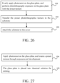
- Apply photoresist on the glass plate, and create a preset texture through exposure and development; and
- The glass plate is placed into chemical solution for etching.
- Through the above technical solution, multiple groups of gratings are arranged at intersections, so that areas where the plurality of groups of textures intersect can share the intersecting gratings, so that the entire texture structure has a closed and fused light and shadow effect. Moreover, the grating units of each group of gratings have inclined grating surfaces, which can achieve a three-dimensional undulating feeling. Combined with the closed light and shadow effect, the entire texture structure can achieve the effect of closed sand dunes, thus having a good visual effect.
- Other features and advantages of the present disclosure will be described in detail in the detailed description that follows.
- The accompanying drawings are used to provide a further understanding of the present disclosure and constitute a part of the specification. They are used to explain the present disclosure together with the following specific embodiments, but do not constitute a limitation of the present disclosure. In the attached picture:
-
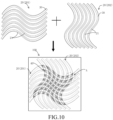
Figure 1 is a schematic diagram of the texture structure of two sets of grating combinations provided by an exemplary embodiment of the present disclosure; -
Figure 2 is a light and shadow trend chart in the embodiment ofFigure 1 ; -
Figure 3a is a schematic diagram of the refraction of light when the height of the grating surface changes; -
Figure 3b is a schematic diagram of the refraction of light when the width of the grating surface changes; -
Figure 4 is a schematic diagram of the texture structure of two sets of grating combinations provided by an exemplary embodiment of the present disclosure; -
Figure 5 is a schematic diagram of the intersection of the texture structure corresponding to the embodiment ofFigure 4 ; -
Figure 6a is a schematic diagram of the effect after cutting the texture structure on the right side ofFigure 4 ; -
Figure 6b is a schematic diagram of the effect after cutting off the texture structure on the right side ofFigure 4 ; -
Figure 6c is a schematic diagram of the effect after cutting the texture structure inFigure 6b ; -
Figure 7 is a schematic diagram of the texture structure of two sets of grating combinations provided by an exemplary embodiment of the present disclosure; -
Figure 8 is a schematic diagram of the intersection of the texture structure corresponding to the embodiment ofFigure 7 ; -
Figure 9a is a schematic diagram of the effect after cutting the texture structure on the right side ofFigure 7 ; -
Figure 9b is a schematic diagram of the effect after cutting off the texture structure on the right side ofFigure 7 ; -
Figure 9c is a schematic diagram of the effect after cutting the texture structure inFigure 9b ; -
Figure 10 is a schematic diagram of the texture structure of two sets of grating combinations provided by an exemplary embodiment of the present disclosure; -
Figure 11 is a partial enlarged view A ofFigure 10 ; -
Figure 12 is a three-dimensional structural diagram corresponding to the figure inFigure 11 ; -
Figure 13 is a cross-sectional view of the intersection inFigure 12 ; -
Figure 14 is a schematic diagram of the texture structure of two sets of grating combinations provided by an exemplary embodiment of the present disclosure; -
Figure 15 is a partial enlarged view B ofFigure 14 ; -
Figure 16 is a three-dimensional structural view corresponding to the figure inFigure 14 ; -
Figure 17 is a schematic structural diagram of a first grating provided by an exemplary embodiment of the present disclosure; -
Figure 18a is an embodiment of cross-sectional view A of the first grating inFigure 17 ; -
Figure 18b is another embodiment of the cross-sectional view A of the first grating inFigure 17 ; -
Figure 19a is an embodiment of cross-sectional view B of the first grating inFigure 17 ; -
Figure 19b is another embodiment of the cross-sectional view B of the first grating inFigure 17 ; -
Figure 20 is a schematic structural diagram of a second grating provided by an exemplary embodiment of the present disclosure; -
Figure 21a is an embodiment of the cross-sectional view C of the second grating inFigure 20 ; -
Figure 21b is another embodiment of the cross-sectional view C of the second grating inFigure 20 ; -
Figure 22a is an embodiment of the cross-sectional view D of the second grating inFigure 20 ; -
Figure 22b is another embodiment of the cross-sectional view D of the second grating inFigure 20 ; -
Figure 23a is a first embodiment of a schematic bottom view of a grating unit provided by an exemplary embodiment of the present disclosure; -
Figure 23b is a second embodiment of a schematic bottom view of a grating unit provided by an exemplary embodiment of the present disclosure; -
Figure 23c is a third embodiment of a schematic bottom view of a grating unit provided by an exemplary embodiment of the present disclosure; -
Figure 23d is a fourth embodiment of a schematic bottom view of a grating unit provided by an exemplary embodiment of the present disclosure; -
Figure 24a is a first embodiment of the extending direction of the grating provided by an exemplary embodiment of the present disclosure; -
Figure 24b is a second embodiment of the extending direction of the grating provided by an exemplary embodiment of the present disclosure; -
Figure 24c is a third embodiment of the extending direction of the grating provided by an exemplary embodiment of the present disclosure; -
Figure 24d is a fourth embodiment of the extending direction of the grating provided by an exemplary embodiment of the present disclosure; -
Figure 25 is a schematic structural diagram of a cover provided by an exemplary embodiment of the present disclosure; -
Figure 26 is a flow chart of a method for preparing a cover plate according to an exemplary embodiment of the present disclosure; -
FIG. 27 is a flow chart of a method for manufacturing a cover plate according to an exemplary embodiment of the present disclosure. - Specific embodiments of the present disclosure will be described in detail below with reference to the accompanying drawings. It should be understood that the specific embodiments described here are only used to illustrate and explain the present disclosure, and are not intended to limit the present disclosure.
- In this disclosure, unless otherwise specified, locative words such as "upper, lower, top, bottom" are generally directions of grating based on substrate as bottom surface. For details, please refer to the drawing directions in
Figures 5 and8 . "Inside and outside" refers to the outline of the corresponding component. Terms used in this disclosure, such as "first, second", etc., are used to distinguish one element from another element and do not have sequence or importance. Furthermore, when the following description refers to the drawings, the same numbers in different drawings represent the same or similar elements unless otherwise indicated. The implementations described in the following exemplary embodiments do not represent all implementations consistent with the present disclosure. Rather, they are merely examples of apparatus and methods consistent with aspects of the disclosure as detailed in the appended claims. - According to a first aspect of the present disclosure, a
texture structure 100 is provided, which can be provided on various products to improve aesthetics. For example, thetexture structure 100 can be provided on the glass cover of a mobile phone to present a desired three-dimensional effect. Specifically, referring toFIGS. 1 to 16 , thetexture structure 100 in the embodiment of the present disclosure includes asubstrate 10 and a plurality of groups of gratings disposed on one side of thesubstrate 10. The plurality of groups ofgratings 20 are cross-disposed on the surface of thesubstrate 10. Thesubstrate 10 here can be a PC (Polycarbonate) sheet, a PET (polyethylene terephthalate) sheet, or a PC/PMMA (poly methyl methacrylate) composite plate material, thesubstrate 10 can also be a glass plate. The surface of thesubstrate 10 may be provided with two, three, four or more groups of gratings that are arranged crosswise. In the embodiment of the present disclosure, for convenience of description, two groups ofgratings 20 will be described below as being crosswise arranged on the surface of thesubstrate 10. For example, the grating includes afirst grating 201 and asecond grating 202, but it should be understood that the number of grating groups in the embodiment of the present disclosure is not limited thereto. As shown inFIGS. 10 and14 , each of the plurality of groups ofgratings 20 includes a plurality of gratingunits 21 arranged side by side and extending in the same direction. Theadjacent grating units 21 may be arranged at intervals as shown in the figures, or may be Gap-free setup. Each of thegrating units 21 in the embodiment of the present disclosure is configured to have agrating surface 30 inclined to thesubstrate 10 , and thegrating surface 30 is used to refract light. - Through the above technical solution, the plurality of groups of
gratings 20 are arranged in intersection, and the texture presented by the intersectinggratings 20 can be shared in the intersection area, so that theentire texture structure 100 has a closed and integrated light and shadow effect. Moreover, the gratingunit 21 of each group ofgratings 20 has an inclined gratingsurface 30, which can achieve a three-dimensional undulating feeling. Combined with the closed light and shadow effect, the entire texture structure can achieve the effect of closed sand dunes, thereby achieving good visual effects. - In the embodiment of the present disclosure, the plurality of groups of
gratings 20 are configured to intersect so that the reflective surface of thetexture structure 100 in any direction changes. The changing trend of the reflective surface refers to that at any angle of thetexture structure 100 when observed, the reflective surfaces reflected by thetexture structure 100 at this viewing angle are not all oriented in one direction, but the orientation of the reflective surfaces has a tendency to change. Referring toFigures 1 and 2 , the lines across the grating 20 inFigure 2 represent the trend of light and shadow. InFigure 1 , after combining thefirst grating 201 and thesecond grating 202, thetexture structure 100 on the right side will be obtained. Atexture structure 100 with a changing trend can be obtained through the combination of the two sets ofgratings 20. For details, please refer to the light and shadow trend chart shown inFigure 2 . When thefirst grating 201 and thesecond grating 202 inFigure 2 exist independently, they each rely on a facing surface to reflect light. After thefirst grating 201 and thesecond grating 202 are crossed and combined, the reflective surfaces change, and the two groups of the light sources reflected by the grating 20 are fused, and thefinal texture structure 100 reflects the fused light and shadow effect. This combination ofgratings 20 in the embodiment of the present disclosure can obtain a gradual light and shadow effect, and the light and shadow presented by each grating 20 are combined at the intersection of thegratings 20, thereby producing a closed light and shadow effect. - According to an embodiment of the present disclosure, the tangent value of the angle between the
grating surface 30 that is inclined to thesubstrate 10 and the surface of thesubstrate 10 may be between 1:150 and 20:1. For example, when the height of the photolithography is 20 µm, that is, when the height of thegrating surface 30 is 20 µm, the corresponding width of thegrating surface 30 can be between 1 µm and 3000 µm. This tangent value range can prevent thegrating surface 30 from being too wide and causing only a plane effect, and the width of thegrating surface 30 is too small to avoid presenting a sloping sand dune effect. For example, in some embodiments, in order to express the light and shadow flow effect, the tangent value of the angle between the grating surface of at least one set ofgratings 20 and the surface of thesubstrate 10 can be set between 2:15 and 20:1, for example, the height of thesurface 30 is 20 µm, and the corresponding width of thegrating surface 30 is between 1 µm and 150 µm. In some embodiments, in order to have both the flow of light and shadow and to reflect the pattern of the arrangement of thegratings 20, the tangent value of the angle between the grating surfaces of at least one group ofgratings 20 and the surface of thesubstrate 10 can be set to 1:150 to 2:15, for example, the height of thegrating surface 30 is 20 µm, and the corresponding width of thegrating surface 30 is between 150 µm and 3000 µm. In the embodiment of the present disclosure, the arrangement of these gratings can also be combined to obtain the desired texture effect. Among them, according to the setting of the photolithography height of 20 µm, the spacing between thegrating units 21 of each group ofgratings 20 can be set between 0 and 200 µm to ensure the texture expression effect. -
Figures 17 to 19 show embodiments of various shapes of thefirst grating 201, whereinFigures 18a and 18b are cross-sectional views A inFigure 17 , representing the cross-section of the grating perpendicular to the extension direction,Figures 19a and Figure 19b is cross-sectional view B inFigure 17 , showing a cross-section of the grating along the extending direction. Here, the vertex position of thefirst grating 201 may always be located at the center line position of the grating 20. InFigure 18a , the cross section of the grating 20 can be configured as a triangle; inFigure 18b , the cross section of the grating 20 is configured as an arcuate shape, that is, the grating 20 has an upwardly arched structure. InFigure 19a , the height of the grating 20 can be kept constant in the extension direction, that is, when the width of the grating 20 remains unchanged, the slope of thegrating surface 30 of the grating 20 in the extension direction can be kept constant; inFigure 19b , the grating 20 can also be configured in an undulating shape, that is, the height of the grating 20 will change. -
Figures 20 to 22 show embodiments of various shapes of thesecond grating 202.Figures 21a and 21b are cross-sectional views C inFigure 20 , which represent the cross-section of the grating perpendicular to the extension direction.Figure 22 is Cross-sectional view D inFigure 20 shows the cross-section of the grating along the extending direction. Here, the vertex position of thesecond grating 202 may vary gradually in direction of extension of grating 20. For example, on the left side ofFIG. 20 , the apex of the grating 20 is aligned with one side of the grating 20, and on the right side ofFIG. 20 , the apex of the grating 20 is aligned with the other side of the grating 20. Specifically, inFigure 21a , the cross section of the grating 20 can be configured as a triangle, and the triangle is configured as a right triangle; inFigure 21b , the cross section of the grating 20 is configured as an arc, that is, the grating 20 has an upwardly arched structure. The vertex of 20 is close to the right side of the cross section. InFigure 22a , similar toFigure 19a , the grating 20 can have a constant height in the extension direction; inFigure 22b , similar toFigure 19b , the grating 20 can also be configured in an undulating shape, that is, the height of the grating 20 will change. -
Figures 23a to 23d show various possible bottom surface shapes of the grating 20, that is, the shape of the contact surface of the grating 20 with thesubstrate 10. The bottom surface can be elliptical in shape as shown inFigure 23a , or rectangular inFigure 23b , or a special shape as shown inFigures 23c and 23d . This disclosure does not limit this, and various possible shapes are within the protection scope of the embodiments of this disclosure. It should be noted here that the structures of thefirst grating 201 and thesecond grating 202 are not limited to the above-mentioned combination methods. The bottom surfaces of various shapes can also be combined with cross sections along the extension direction and perpendicular to the extension direction to formgratings 20. The embodiments are not limited to the above-mentioned embodiments and those shown in the drawings, and can be adjusted and combined according to the actual desired effects. - In the embodiment of the present disclosure, the plurality of groups of
gratings 20 may includecurved gratings 203 extending in a curved manner orlinear gratings 204 extending in a straight line, or may include both at the same time. Referring toFigures 24a to 24d , various possible extension directions of the grating 20 are shown.Figure 24a shows alinear grating 204 that extends straight, andFigures 24b to 24d show acurved grating 203 that extends in a curved manner. Specifically, Ground,Figure 24b shows an S-shaped grating,Figure 24c shows an M-shaped grating,Figure 24d shows an O-shaped grating, and the extending direction of the grating 20 shown inFigures 24a to 24d is only the description is illustrative and not intended to limit the disclosure. - In some embodiments, the plurality of sets of
gratings 20 may include at least two sets ofcurved gratings 203 extending in a curved manner. Through thetexture structure 100 obtained by the intersection of the two sets ofcurved gratings 203, a changing trend of the reflective surface in any direction can be obtained, that is, the effect of light and shadow changes is obtained, thereby achieving the visual effect of closed sand dunes. On this basis, one or more groups oflinear gratings 204 orcurved gratings 203 can be added arbitrarily. - In some embodiments, when the plurality of sets of
gratings 20 only include two sets of gratings, and one or both sets of gratings arelinear gratings 204 that extend straight, the slope of thegrating surface 30 of thelinear gratings 204 of the two sets of gratings can be set differently in the extension direction. For example, the slope of thegrating surface 30 can be adjusted by changing the position of the vertex of the grating 20 in the width direction of the grating or by changing the height of the grating 20. By changing the slope of thegrating surface 30 of thelinear grating 204, it is also possible to obtain the changing trend of the reflective surface shown by the texture structure in any direction, that is, to obtain the effect of changing light and shadow, thereby achieving the visual effect of a closed sand dune. - Referring to
Figures 3a and 3b , the reflection conditions of light on variousgrating surfaces 30 are shown. The arrows pointing to the left in the figures represent the paths of the incident light, and the arrows in other directions represent the paths of the reflected light. It can be seen from the figure that inFigure 3a , in order from top to bottom, the width of the grating 20 remains unchanged and the height gradually decreases (the slope of thegrating surface 30 gradually decreases). According to the path of the reflected light, it can be seen that the light reflected to the human eye gradually decreases; inFigure 3b , in order from top to bottom, the height of the grating 20 remains unchanged and the width gradually increases (the slope of thegrating surface 30 gradually decreases), and according to the path of the reflected light, it can be seen that the light reflected to the human eye also gradually became less and less. It can be seen from this that the smaller the slope of thegrating surface 30 is, the less light is reflected, and the larger the slope of thegrating surface 30 is, the more light is reflected. Based on this principle, after the plurality of groups ofgratings 20 are intersected, for example, after the plurality of groups ofgratings 20 are intersected through computer operating software, the intersection positions of the plurality of groups of gratings (such as two sets of gratings) can also be processed according to the actual required texture effects. That is, the slope of the grating surface at the intersection position is processed to obtain the expected texture effect. - Specifically, referring to
Figures 4 and 5 , the arrows inFigure 4 indicate the direction of the reflective surface of the grating. InFigure 4 , thefirst grating 201 and thesecond grating 202 intersect to obtain atexture structure 100 in which the direction of the reflective surface changes. In this embodiment, the processing of the intersection after the gratings are crossed can be explained with reference toFigure 5 . The thin solid line inFigure 5 represents the cross section of thefirst grating 201, and the dotted line represents the cross section of thesecond grating 202, the thick solid line represents the cross section of theintersection 40 obtained after processing the intersecting gratings. In the figure, the area where orthographic projections of the plurality of groups ofgratings 20 overlap on thesubstrate 10 is configured as an overlapping area. The structure of the grating 20 corresponding to the overlapping area is configured as anintersection 40. The overlapping area has a plurality of position points A(x, y), only one point is shown in the figure, but it can be understood that the overlapping area is composed of several position points. The number ofintersecting gratings 20 in the overlapping area is represented by n. The heights corresponding to the plurality of groups of intersectinggratings 20 at each position point A (x, y) are h1, h2,..., hn, respectively. The height ofintersection portion 40 at the corresponding position point A (x, y) is represented by H. In one embodiment, the value of H may be the average height of the plurality of groups of gratings (h1+h2+...+hn)/n. As shown inFigure 5 , the plurality of groups ofgratings 20 include afirst grating 201 and asecond grating 202. The height of thefirst grating 201 corresponding to the position point A (x, y) is h1, and the height of thesecond grating 202 corresponding to the position point A (x, y) is h2, and the height corresponding to theintersection 40 at the corresponding position point A (x, y) is H=(h1+h2)/2. When designing, you can first intersect the two sets of gratings, and then cut the gratings in the overlapping area according to the preset height value of theintersection 40. For example, inFigure 5 , cut off the grating outside the contour formed by the thick solid line and thesubstrate 10 to obtain the expectedintersection 40. According to the experimental results, when the height of theintersection 40 is averaged as shown inFigure 5 , the grating 20 and theintersection 40 can smoothly transition, thereby having a fused light and shadow effect as shown on the right side ofFigure 4 , to obtain a better dune effect. - In addition, referring to
Figures 7 and 8 , the expression methods of each parameter and each grating are the same as those of the previous embodiment. but what is different from the embodiment shown inFigures 4 and 5 is that in this embodiment, the value of the height H corresponding to the corresponding position point A (x, y) of theintersection 40 can be the smallest one among h1, h2,...,hn, that is, can be the smaller one among the heights of plurality of groups of gratings. For example, inFIG. 8 , the height of thefirst grating 201 is h1, the height of thesecond grating 202 is h2, and h1<h2. In this embodiment, the height H of theintersection 40 may be h1. Similarly, the excess grating in the overlapping area can be cut in the same manner as above to obtain the expectedintersection 40. According to the method of obtaining theintersection 40 as shown inFIG. 8 , the light and shadow effect shown on the right side ofFIG. 7 can be obtained. In other embodiments of the present disclosure, the height value of the intersection is not limited to this, and can be adjusted according to the actual texture effect required. For example, the intersection grating can be set any value between the lowest value and the highest value of the height of the overlapping area. - In the embodiment of the present disclosure, the
intersection 40 may be configured as a pyramid or a prism, that is, the cross section of theintersection 40 may be configured as a triangle as shown inFIG. 8 or an irregular trapezoidal structure as shown inFIG. 5 . It can be understood that the shape of theintersection portion 40 in the embodiment of the present disclosure is not limited thereto, and can be modified and adjusted according to the shape of the grating. - Since each group of
gratings 20 has multiplegrating units 21, thetexture structure 100 formed after intersection may havemultiple intersections 40. In the embodiment of the present disclosure, with reference toFIGS. 10 to 12 and14 to 16 , the shapes of themultiple intersection portions 40 can be set to be different. For example, the different shapes of theintersection portions 40 can be achieved by relying on the shape change of the grating itself, or the slope of thegrating surface 30 of theintersection 40 can be changed by changing the vertex position of theintersection 40, or the size of theintersection 40 can be changed, so as to achieve refraction and reflection of light at different angles and different intensities, This achieves sand dune light and shadow with closed three-dimensional characteristics. - In addition, in the embodiment of the present disclosure, the
intersection portion 40 can also be divided into multiple small bodies again, or the distance between theintersection portions 40 can be changed by cutting off the gratings betweenadjacent intersection portions 40 to modify the texture. The effect presented by the structure is adjusted to achieve the desired effect. For example,FIG. 6a shows the effect of cutting thetexture structure 100 inFIG. 4, and FIG. 6 b shows the effect of raster cutting of thetexture structure 100 inFIG. 4 to increase the gap between theintersections 40,Figure 6c shows the effect of cutting thetexture structure 100 inFigure 6b again. As another example,FIG. 9a shows the effect of cutting thetexture structure 100 inFIG. 7, and FIG. 9b shows the effect of raster cutting of thetexture structure 100 inFIG. 7 to increase the gap between theintersections 40,Figure 9c shows the effect after cutting thetexture structure 100 inFigure 9b again. - According to an embodiment of the present disclosure, with reference to
Figures 10 to 12 , after two sets of gratings intersect, theintersection 40 can be formed into a plurality of quadrangular pyramids, and the shapes of the quadrangular pyramids are different. Each quadrangular pyramid can also be divided into the shape shown inFigure 13. FIG. 13 shows a cross-sectional view after the intersection is divided.Figures 14 to 16 show the effect of another grating intersection. Theintersection 40 here can be configured as an irregular pyramid structure. For example, the bottom edge of the pyramid can be a curve, the sides of a pyramid can be curved. - According to a second aspect of the present disclosure, a cover plate is also provided. The cover plate may include the above-mentioned
texture structure 100. The cover plate has all the beneficial effects of the above-mentionedtexture structure 100, which will not be described again here. Specifically, referring toFIG. 25 , the cover plate may also include a color-filling layer 200 filled on thetexture structure 100. For example, thetexture structure 100 may be plated with a film layer of the same color. By utilizing the light and shadow of the undulating sand dunes in this disclosure, it may be made to appear different. The color change improves the aesthetics of the cover product. - According to a third aspect of the present disclosure, a mobile terminal is also provided. The mobile terminal includes the above-mentioned cover plate and has all the beneficial effects of the above-mentioned cover plate, which will not be described again here. The cover can be used as a back shell of the mobile terminal to improve the visual effect. Among them, mobile terminals can include mobile phones, tablets, laptops, etc.
- According to a fourth aspect of the present disclosure, a method for preparing a cover plate is also provided. Referring to
Figure 26 , the method includes: instep 101, evenly apply photoresist on the glass plate, and perform photolithography exposure on the glass plate with the preset texture. The preset texture here is the texture obtained by the above-mentioned plurality of groups ofgratings 20 after cross-processing. The designed preset texture data can be transferred to the computer, and then photolithography exposure is performed on the glass plate according to the data; instep 102, transfer the preset photolithographic texture to thesubstrate 10. For example, afterstep 101, the texture afterstep 101 is developed, dried, and plasma cleaned, and then transferred to thesubstrate 10 by UV transfer; And instep 103, thesubstrate 10 is bonded to the cover plate through processes such as coating, printing, cutting, and lamination, thereby obtaining a cover plate with a preset texture. As mentioned above, thesubstrate 10 can be one of PC sheet, PET sheet, and PC/PMMA composite sheet. - Typically, the cover itself may include a glass plate, which may be constructed directly as the
substrate 10 of thetextured structure 100. Referring toFigure 27 , in the embodiment of the present disclosure, another method of preparing a cover plate may include: instep 104, spreading photoresist on the glass plate, and producing texture structure from pre-stored texture data in the computer through exposure and development; and instep 105, place the glass plate into a chemical etching tank for etching. Due to the protective effect of photoresist on glass, areas with thicker resist will resist etching for a longer time, while areas with thinner resist will resist etching for shorter periods of time. The glass of thesubstrate 10 will leak out before the thicker resist. Therefore, the glass placed in the etching tank will be uneven. With a reasonable etching time, the texture can be copied to the glass plate of the cover plate, thereby forming thetexture structure 100 in the embodiment of the present disclosure and obtaining the desired cover plate. - The preparation method of the cover plate in the embodiment of the present disclosure may also include: coating, spraying or printing the cover plate provided with the texture structure, thereby forming a cover plate product with a gradient color.
- The preferred embodiments of the present disclosure have been described in detail above with reference to the accompanying drawings. However, the present disclosure is not limited to the specific details in the above-mentioned embodiments. Within the scope of the technical concept of the present disclosure, the technical solution of the present disclosure can be simplified in various ways, these simple modifications all belong to the protection scope of the present disclosure.
- In addition, it should be noted that each of the specific technical features described in the above-mentioned specific embodiments can be combined in any suitable manner without conflict. In order to avoid unnecessary repetition, this disclosure describes various possible combinations. The combination method will not be further explained.
- In addition, any combination of various embodiments of the present disclosure can also be carried out, and as long as they do not violate the idea of the present disclosure, they should also be regarded as the contents disclosed in the present disclosure.
Claims (16)
- A texture structure (100), comprising:substrate (10); anda plurality of groups of gratings (20) arranged on one side of the substrate (10), the plurality of groups of gratings (20) being arranged on the surface of the substrate (10) in a crisscross pattern, each of the plurality of groups of gratings (20) comprising a plurality of grating units (21) arranged side by side and extending in the same direction, and each of the plurality of grating units (21) being configured to have a grating surface (30) inclined to the substrate (10).
- The texture structure (100) according to claim 1, wherein the plurality of groups of gratings (20) are configured to intersect so that a reflective surface of the texture structure (100) in any direction exhibits a changing trend.
- The texture structure (100) according to claim 1 or 2, wherein the plurality of groups of gratings (20) comprise:curved extended curved grating (203) and/orstraight line extending linear grating (204).
- The texture structure (100) according to any one of claims 1-3, wherein the plurality of groups of gratings (20) comprise at least two groups of curved extended curved gratings (203).
- The texture structure (100) according to any one of claims 1-3, wherein the plurality of groups of gratings (20) include two groups of gratings (20), and at least one of the two groups of gratings (20) is a straight-line extending linear grating (204), the slope of the grating surface (30) of the linear grating (204) differs in the extension direction.
- The texture structure (100) according to any one of claims 1-5, wherein the cross section of the grating (20) perpendicular to the extension direction is configured in a triangular or arcuate shape.
- The texture structure (100) according to any one of claims 1-6, wherein the tangent value of the angle between the grating surface (30) and the surface of the substrate (10) is between 1:150 and 20:1.
- The texture structure (100) according to claim 7, wherein the tangent value of the angle between the grating surface (30) of at least one set of gratings (20) and the surface of the substrate (10) is between 2:15 and 20:1, and/or,
the tangent value of the angle between the grating surface (30) of at least one set of gratings (20) and the surface of the substrate (10) is between 1:150 and 2:15. - The texture structure (100) according to any one of claims 1-8, wherein an area where orthographic projections of the plurality of groups of gratings (20) overlap on the substrate (10) is configured as an overlapping area, and the structure of the grating (20) corresponding to the overlapping area is configured as an intersection portion (40), the overlapping area has a plurality location points A (x, y) , the heights corresponding to the plurality of groups of intersecting gratings (20) at each position point A (x, y) are h1, h2 ,..., hn respectively, the corresponding height H to the intersection (40) at the corresponding position point A (x , y) is (h1 +h2 +...... +hn )/n, or the height H corresponding to the intersection at the corresponding position point A(x, y) is the smallest one among h1, h2,...,hn, where n is the number of the plurality of gratings (20) intersecting in the overlapping area.
- The texture structure (100) according to claim 9, wherein the intersection (40) is configured as a pyramid or a prism.
- The texture structure (100) according to claim 9 or 10, wherein the texture structure (100) has a plurality of intersections (40), and the shapes of the plurality of intersections (40) are different.
- A cover plate, wherein comprising the texture structure (100) according to any one of claims 1-11.
- A mobile terminal, wherein comprising a cover plate according to claim 12.
- A method for preparing a cover plate, wherein the cover plate comprising the texture structure (100) according to any one of claims 1-11, and the preparation method includes:evenly applying photoresist on the glass plate, and performing photolithography exposure on the glass plate with the preset texture;transferring the preset photolithographic texture to the substrate (10); andattaching the substrate (10) to the cover.
- The preparation method according to claim 14, wherein the substrate (10) includes one of PC sheets, PET sheets, and PC/PMMA composite sheets.
- A method for preparing a cover plate, wherein the cover plate comprises a glass plate configured as the substrate (10) and the textured structure (100) according to any one of claims 1-11, the preparation method comprising:apply photoresist on the glass plate and create a preset texture through exposure and development; andthe glass plate is placed into chemical solution for etching.
Applications Claiming Priority (2)
| Application Number | Priority Date | Filing Date | Title |
|---|---|---|---|
| CN202210347758.7A CN116931144B (en) | 2022-04-01 | 2022-04-01 | Texture structure, cover plate, mobile terminal and preparation method of cover plate |
| PCT/CN2023/083415 WO2023185635A1 (en) | 2022-04-01 | 2023-03-23 | Texture structure, cover plate, mobile terminal, and preparation method for cover plate |
Publications (2)
| Publication Number | Publication Date |
|---|---|
| EP4506184A1 true EP4506184A1 (en) | 2025-02-12 |
| EP4506184A4 EP4506184A4 (en) | 2026-03-25 |
Family
ID=88199293
Family Applications (1)
| Application Number | Title | Priority Date | Filing Date |
|---|---|---|---|
| EP23778004.4A Pending EP4506184A4 (en) | 2022-04-01 | 2023-03-23 | TEXTURE STRUCTURE, COVER PLATE, MOBILE DEVICE AND COVER PLATE MANUFACTURING METHOD |
Country Status (6)
| Country | Link |
|---|---|
| US (1) | US20250020840A1 (en) |
| EP (1) | EP4506184A4 (en) |
| JP (1) | JP2025512898A (en) |
| KR (1) | KR20240160635A (en) |
| CN (1) | CN116931144B (en) |
| WO (1) | WO2023185635A1 (en) |
Family Cites Families (24)
| Publication number | Priority date | Publication date | Assignee | Title |
|---|---|---|---|---|
| WO1990011197A1 (en) * | 1989-03-17 | 1990-10-04 | Kooperativ 'merkury' | Decorative material with colour-dynamic surface and method of obtaining it |
| AUPP444498A0 (en) * | 1998-07-02 | 1998-07-23 | Commonwealth Scientific And Industrial Research Organisation | Diffractive structure with interstitial elements |
| AU3270400A (en) * | 2000-03-14 | 2001-09-24 | Kernel, A.S. | Glass facing plate |
| WO2003107047A1 (en) * | 2002-06-12 | 2003-12-24 | Giesecke & Devrient Gmbh | Method for producing grating images |
| DE102005027737B4 (en) * | 2005-06-16 | 2013-03-28 | Saint-Gobain Glass Deutschland Gmbh | Use of a transparent disc with a three-dimensional surface structure as a cover plate for components for the use of sunlight |
| US8233218B1 (en) * | 2007-07-18 | 2012-07-31 | Lightsmyth Technologies Inc. | Decorative, ornamental, or jewelry articles having diffraction gratings |
| JP5391670B2 (en) * | 2007-12-27 | 2014-01-15 | セイコーエプソン株式会社 | Manufacturing method of fine structure |
| KR101597014B1 (en) * | 2009-02-26 | 2016-02-24 | 다이니폰 인사츠 가부시키가이샤 | Mold for forming optical sheet, and method for manufacturing mold |
| JP5926736B2 (en) * | 2011-10-13 | 2016-05-25 | Hoya株式会社 | Manufacturing method of cover glass for portable device |
| WO2013084900A1 (en) * | 2011-12-08 | 2013-06-13 | 旭硝子株式会社 | Laminate and laminate manufacturing method |
| JP3179508U (en) * | 2012-05-10 | 2012-11-08 | 雅之 下山 | Mobile phone cover filled with flexible material on part of the surface |
| CN109301081B (en) * | 2017-07-25 | 2020-11-27 | 上海视涯技术有限公司 | Shadow mask for OLED evaporation, method for making the same, and method for making OLED panel |
| CN107835276A (en) * | 2017-12-08 | 2018-03-23 | 南昌欧菲光科技有限公司 | Flexible cover plate of electronic equipment and preparation method thereof and electronic equipment |
| US11932001B2 (en) * | 2018-06-15 | 2024-03-19 | Lg Chem, Ltd. | Decoration member |
| JP2020173426A (en) * | 2019-04-08 | 2020-10-22 | 大日本印刷株式会社 | Optical element |
| CN110263773B (en) * | 2019-07-31 | 2021-08-06 | 厦门天马微电子有限公司 | Display module, display device and manufacturing method of grating film layer |
| CN211014693U (en) * | 2019-11-15 | 2020-07-14 | 苏州胜利精密制造科技股份有限公司 | Optical film with light and shade change and light column effect superposition and electronic product cover plate |
| CN211702723U (en) * | 2019-12-23 | 2020-10-16 | 江西沃格光电股份有限公司深圳分公司 | Cover plate and electronic equipment |
| CN211843904U (en) * | 2019-12-26 | 2020-11-03 | 昇印光电(昆山)股份有限公司 | Decorative membrane with pyramid texture and cover plate carrying decorative membrane |
| CN111016522B (en) * | 2019-12-29 | 2021-10-29 | 昇印光电(昆山)股份有限公司 | A decorative film, a mold, a preparation method thereof, and a cover plate for electronic equipment |
| EP4208743A1 (en) * | 2020-09-01 | 2023-07-12 | Snap, Inc. | Methods for designing diffraction grating for augmented reality or virtual reality display and diffraction grating for augmented reality or virtual reality display |
| CN114280711B (en) * | 2020-09-28 | 2023-07-11 | 比亚迪股份有限公司 | Transparent plate, manufacturing method thereof, shell and mobile terminal |
| CN113955946A (en) * | 2021-10-20 | 2022-01-21 | 滁州明永光电科技有限公司 | Novel texture effect manufacturing method |
| CN114213032A (en) * | 2022-01-11 | 2022-03-22 | 江西晶创科技有限公司 | Process for etching CD (compact disc) pattern effect on glass surface |
-
2022
- 2022-04-01 CN CN202210347758.7A patent/CN116931144B/en active Active
-
2023
- 2023-03-23 JP JP2024558091A patent/JP2025512898A/en active Pending
- 2023-03-23 WO PCT/CN2023/083415 patent/WO2023185635A1/en not_active Ceased
- 2023-03-23 EP EP23778004.4A patent/EP4506184A4/en active Pending
- 2023-03-23 KR KR1020247033724A patent/KR20240160635A/en active Pending
-
2024
- 2024-09-27 US US18/899,380 patent/US20250020840A1/en active Pending
Also Published As
| Publication number | Publication date |
|---|---|
| US20250020840A1 (en) | 2025-01-16 |
| JP2025512898A (en) | 2025-04-22 |
| CN116931144A (en) | 2023-10-24 |
| EP4506184A4 (en) | 2026-03-25 |
| CN116931144B (en) | 2024-10-11 |
| KR20240160635A (en) | 2024-11-11 |
| WO2023185635A1 (en) | 2023-10-05 |
Similar Documents
| Publication | Publication Date | Title |
|---|---|---|
| EP4561276A1 (en) | Decorative member, housing of electronic device, and electronic device | |
| JP2003004916A (en) | Window material for display device, method for manufacturing the same, and display device | |
| KR101926648B1 (en) | Composite pattern sheet, composite pattern mold with composite pattern sheet and manufacturing method thereof, and electronic device cover film with composite pattern sheet | |
| US20240351367A1 (en) | Glitter module and electronic product | |
| KR20230071185A (en) | Transparent plate and its manufacturing method, housing, and mobile terminal | |
| US20250020840A1 (en) | Texture structure, cover plate, mobile terminal, and preparation method for cover plate | |
| JP2026506795A (en) | Decorative member, housing, and electronic device | |
| EP4568431A1 (en) | Decorative substrate and preparation method therefor, cover plate and electronic device | |
| JP2025530813A (en) | Decorative substrate, its manufacturing method and its application | |
| CN109041477B (en) | Decorative film | |
| KR101012778B1 (en) | Reflective structure with directional divergence of reflection and device with same | |
| CN218735487U (en) | Trims, housings and electronics | |
| EP4670998A1 (en) | DECORATIVE PART, ELECTRONIC DEVICE AND MANUFACTURING METHOD FOR DECORATIVE PART | |
| CN220419601U (en) | Optical structure, terminal housing and terminal | |
| EP4523925A1 (en) | Decorative substrate and manufacturing method therefor, cover plate and electronic device | |
| CN219181794U (en) | Decoration, casing of electronic equipment and electronic equipment | |
| EP4572543A1 (en) | Decorative plate and preparation method therefor, and electronic device | |
| CN118544725A (en) | Decorative parts, housings and electronic equipment | |
| CN117956714A (en) | A decorative board and its preparation method and application | |
| JP2025539728A (en) | Decorative plate, cover plate, and electronic device | |
| CN120716374A (en) | Decorative film, housing and electronic equipment | |
| CN118354543A (en) | Decoration, shell and electronic equipment |
Legal Events
| Date | Code | Title | Description |
|---|---|---|---|
| STAA | Information on the status of an ep patent application or granted ep patent |
Free format text: STATUS: THE INTERNATIONAL PUBLICATION HAS BEEN MADE |
|
| PUAI | Public reference made under article 153(3) epc to a published international application that has entered the european phase |
Free format text: ORIGINAL CODE: 0009012 |
|
| STAA | Information on the status of an ep patent application or granted ep patent |
Free format text: STATUS: REQUEST FOR EXAMINATION WAS MADE |
|
| 17P | Request for examination filed |
Effective date: 20240927 |
|
| AK | Designated contracting states |
Kind code of ref document: A1 Designated state(s): AL AT BE BG CH CY CZ DE DK EE ES FI FR GB GR HR HU IE IS IT LI LT LU LV MC ME MK MT NL NO PL PT RO RS SE SI SK SM TR |
|
| DAV | Request for validation of the european patent (deleted) | ||
| DAX | Request for extension of the european patent (deleted) | ||
| A4 | Supplementary search report drawn up and despatched |
Effective date: 20260225 |
|
| RIC1 | Information provided on ipc code assigned before grant |
Ipc: B44C 5/04 20060101AFI20260219BHEP Ipc: H05K 5/03 20060101ALI20260219BHEP Ipc: G02B 5/18 20060101ALI20260219BHEP Ipc: H04M 1/02 20060101ALI20260219BHEP |